Abstract
Increasing automotive powertrain electrification is impacting drivetrain complexity and the profiles of the fluids needed. Since the millennium, drivetrain fluid viscosities have been reduced for better efficiency, but this new challenge is driving them to unprecedented low levels. This paper assesses some of the potential implications of ultra-low viscosity fluids on drivetrain functionality and durability. Model formulations have been prepared from a variety of base fluids combined with additive packages. These have been evaluated in typical automotive drivetrain rig tests, as well as with some selected functional tests. In addition, the thermo-oxidative stability and electrical and thermal properties of the fluids were compared. Based on the results, the impact of low viscosity fluids on drivetrain functionality and durability varies depending on the performance parameter evaluated. For example, gear scuffing and bearing wear is highly dependent on additives, whilst gear and bearing fatigue is mainly affected by fluid viscosity. However, by carefully balancing base fluids and additives, acceptable component and fluid durability can be achieved. With respect to new electric drivetrain performance needs, the thermal properties of the finished fluid are essentially dependent on the base fluid composition, whilst its electrical properties are more influenced by additive chemistry, with some secondary impact from base fluid composition.
1. Introduction
Automotive powertrains are undergoing a major transformation, posing significant challenges for drivetrain component and fluid manufacturers alike.
Most importantly, there is a continuous desire for the lowest lubricant viscosity possible to enhance powertrain efficiency. Specifically for drivetrain fluids, recent changes to the SAE J306 Automotive Gear Lubricant Viscosity Classification [1] are a good reflection of this trend. With its most recent revision from 2019, new lower viscosity classifications have been introduced. It is to be noted though, that ongoing drivetrain development projects include ultra-low viscosity (ULV) fluids with even lower viscosity levels than defined in SAE J306. Balancing this trend without compromising other fluid properties such as anti-wear protection, volatility or flash point remains a continuous challenge for both drivetrain component designers and fluid formulators. The effect and suitability of low viscous oil formulations in view of efficiency and durability in principle were shown by Mayer [2] and Wittek [3] in 2014.
On the other hand, increasing powertrain electrification adds new requirements to fluid performance profiles, as also described in [4,5]. The fluid’s electrical properties can have a significant impact on drivetrain component functionality and durability, as well as the fluid service life. In addition, electric powertrains by design generate heat, potentially exposing fluids and components to significantly higher temperatures than previously observed in conventional drivetrain applications. Whilst the higher temperatures generated cause greater thermal stress on the fluid and components, improved cooling capabilities of the fluid can help disperse the heat and minimize damage due to overheating.
In a joint effort, Schaeffler Technologies and ExxonMobil have set up a project addressing the described challenges, evaluating some implications for future drivetrain design and fluid formulations, and identifying potential solutions to mitigate any detrimental impacts.
Some of the results and insights generated in this project are discussed in this paper. First, some generic fluid properties and performance aspects were evaluated using industry testing standards:
- Pitting and scuffing resistance
- Thermo-oxidative stability and copper compatibility
- Thermo-dynamic and electrical properties
Based on the general fluid performance data, test candidates were selected for the next stage of testing, to evaluate the reduced fluid viscosity impact on the functionality and durability of some transmission components:
- Synchronizer units
- Rolling bearings
2. Materials and Methods
2.1. Materials
2.1.1. Base Fluids
Depending on their design and applications, contemporary drivetrain lubricants can include a wide range of base fluids provided by the mineral oil and chemical industry. For the purposes of this study, considering the targeted viscosity levels and other limiting parameters such as flash point, only base fluids of API Group IV (polyalphaolefins) and Group V (esters of various types and alkylated naphthalene) [6] have been used to reduce the variability of the test results;
- Produced by the chemical industry, these base fluids are typically well defined in their molecular structure, with a very narrow molecular distribution.
- More specifically, variation in volatility and related properties, such as flash point, are kept at an acceptable minimum even at the lowest viscosity levels evaluated in this study.
2.1.2. Additives
Three additive packages have been used for this study:
- GO-Add is a general market additive package for automotive drivetrain applications, designed to meet API GL-4 or GL-5 [7] performance levels at the appropriate treat rate. For the purposes of this study, a treat rate of 7.5%, equivalent to the API GL-5 performance level, was selected.
- EV-Add1 and EV-Add2 are additive packages from two different suppliers specifically designed to meet the needs of automotive electric powertrains. Following supplier recommendations, treat rates of 6.0 and 3.5%, respectively, were applied.
2.1.3. Finished Fluids
- While more than 30 model formulations have been blended covering a wide range of fluid/additive combinations, a full in-depth analysis of all test data and results would go beyond the scope of this paper. The insights and conclusions shared and discussed in this paper are based on the fluids shown in the following Table 1. The key product development aspects discussed have been evaluated based on 3 additive packages, 3 different types of base fluid chemistry, and finished fluid viscosities between 1.4 mm2/s and 4.4 mm2/s at 100 °C. Fluid SYN is a Schaeffler Technologies internal reference fluid, used for synchronizer testing only.
 Table 1. Basefluid/Additive combinations.
 - All others are model fluids blended by ExxonMobil.
2.2. Test Methods
A wide variety of laboratory, bench, and rig tests are available to specify fluid performance requirements. While these are often specific to the respective drivetrain designs and materials, some testing standards are commonly required in most drivetrain fluid specifications. The test standards and conditions listed in Table 2 have been used to characterize the performance of the test fluids discussed in this paper and to preselect candidates for final component testing. More details on the test procedures are shown in respective paragraphs.
Table 2.
Test standards.
2.2.1. Scuffing Resistance
Gear scuffing is a severe form of wear occurring in highly loaded contacts, causing transfer of metal from one tooth surface to another. The FZG scuffing test is the most widely used rig test to assess a fluid’s scuffing resistance. Gears of defined geometry are run under predefined conditions of load, speed and temperature. Load is increased at defined intervals until scuffing occurs; the lowest load step at which scuffing is observed is reported as the fail load stage. Some selected test results are shown in the following Figure 1.
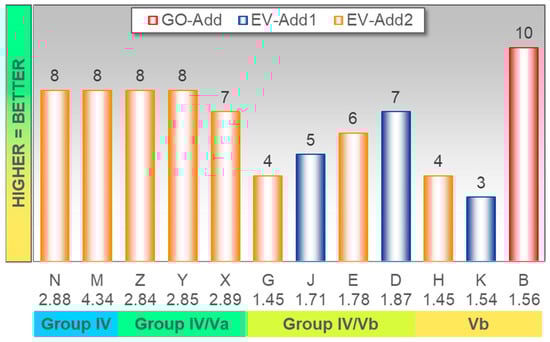
Figure 1.
FZG Scuffing A10/16.6R/90, fail load stage. Fluid labels on the category axis include viscosity at 100 °C in mm2/s and base fluid composition.
Clearly, anti-scuffing performance is predominantly driven by additive chemistry. Fluid B based on a general market gear oil package achieves the best performance even at very low viscosity levels. On the other hand, for Group V base fluids, a noticeable impact of base fluid chemistry was also observed.
2.2.2. Pitting Resistance
Pitting is a form of surface-near material fatigue, which is the prime failure mechanism for gears and rolling bearings, limiting their service life. The FZG pitting test is widely used to assess the gear pitting resistance of a fluid. Gears of defined geometry are run under predefined conditions of load, speed, and temperature until pitting occurs. Due to time limitations, only some selected fluids based on the same additive packages have been run in this test—the results are shown in the following Figure 2.
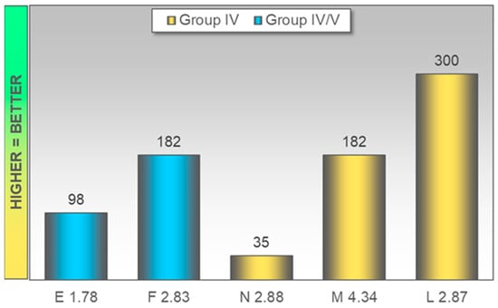
Figure 2.
FZG Pitting PT-C/8.3/LS9/90, operating hours. Fluid labels on the category axis include viscosity at 100 °C in mm2/s.
Evidently when it comes to gear pitting resistance, base fluid composition can be an important tool for the fluid formulator in various ways.
- Fluids E/F and M/N, respectively, are based on identical base fluid components, with relative proportions only adjusted to meet the target viscosity level. In both cases, a higher viscosity is beneficial for pitting resistance.
- However, base fluid impact goes beyond viscosity considerations. Fluid L uses the same principal base fluid chemistry as Fluid M, but uses a very different balance of constituting base fluid viscosities to achieve the desired viscosity level, resulting in a significant enhancement to pitting resistance.
2.2.3. Thermo-Oxidative Stability
Oxidation testing is commonly used in various forms to predict fluid service life; the CEC L-048 method is typically preferred by European OEMs and transmission manufacturers. The test oil is blown with air under predefined conditions of air flow and temperature. Changes to selected fluid parameters such as viscosity and TAN after a defined test time are reported. Selected test results are shown in the following Figure 3.
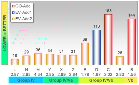
Figure 3.
Thermo-oxidative stability at 150 °C and 5 L/hour air over 192 h, peak area increase in %. Fluid labels on the category axis include viscosity at 100 °C in mm2/s and base fluid composition.
For the base fluid and additive technologies evaluated here, additive chemistry is the dominating factor for fluid stability against thermo-oxidative degradation. Some minor impact of base fluid chemistry can also be observed, but there is no impact of finished fluid viscosity.
2.2.4. Copper Compatibility
With the rise of automotive powertrain electrification, fluid compatibility with copper-based electric current conductors has become a significant factor affecting drivetrain functionality and durability. Results from a modified ASTM D130 copper compatibility test are shown in the following Figure 4. In this test, a copper strip is immersed in the test oil under elevated temperatures for a defined time period. After the test, the weight change of the copper strip is recorded.
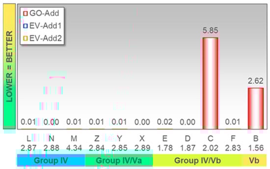
Figure 4.
Copper compatibility at 160 °C over 70 h, copper strip weight change in %. Fluid labels on the category axis include viscosity at 100 °C in mm2/s and base fluid composition.
Test results clearly show the benefits of additive packages specifically designed for electric powertrains. Conventional drivetrain additive technologies would typically contain sulfur as a main EP/AW component that can cause significant corrosion of copper-based electric conductors, and thus potentially lead to catastrophic failures. Within the scope of this study, neither the finished fluid viscosity nor base fluid composition had any impact.
2.2.5. Thermo-Dynamic Properties
Electric powertrains by design can generate a lot of heat, caused by the electric current flow. OEMs have been exploring opportunities to utilize transmission lubricants to dissipate the heat thus generated. Cooling with the drivetrain fluid can help reduce component temperatures and the related risk of premature failures. For the design and effectiveness of heat transfer systems, heat capacity and thermal conductivity are key fluid parameters.
Finished lubricants heat capacity basically results from the properties of the constituting base fluids; for the fluids within the scope of this project, viscosity had no direct impact. In the following Figure 5, specific heat capacities according to ASTM E1269 [12] are shown for some test fluids and their constituting base fluids.
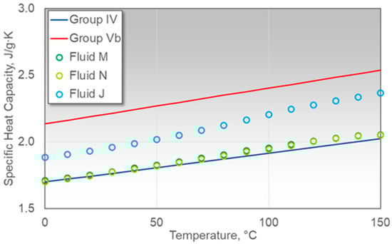
Figure 5.
Specific heat capacity versus temperature.
- The blue line represents a Group IV base fluid grade used in both Fluid M and N, combined with a higher and lower viscosity grade, respectively, to achieve the desired viscosity profile. Within the viscosity ranges discussed here, differences in the heat capacities of finished and base fluids are more or less within test precision.
- About half of Fluid J is made from the Group V base fluid represented by the red line. Over the temperature range considered here, the heat capacity of Fluid J is just between that of the constituting base fluids. It should be noted though that the heat capacities of base fluids do not necessarily combine linearly.
Finished fluid thermal conductivities are also basically dependent on the properties of the constituting base fluids, but with more complex interdependencies. Contrary to heat capacity, fluid viscosity has an impact. The thermal conductivity of some test fluids and constituting base fluids according to ASTM D7896 [13] are shown in the following Figure 6.
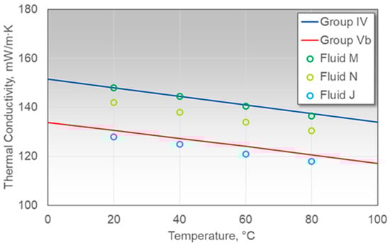
Figure 6.
Thermal conductivity versus temperature.
- Fluid M has a similar viscosity level to the Group IV base fluid it is made of, and both show about the same thermal conductivity. Fluid N also contains some portion of the Group IV base fluid, but combined with a lower viscosity grade, resulting in lower finished fluid viscosity and also, consequently, lower thermal conductivity.
- Fluid J is significantly lower in viscosity and thermal conductivity than Fluid N. The Group V base fluid contained in Fluid J has an even lower viscosity, but in this case, the viscosity effect is obviously outweighed by the chemistry effect.
2.2.6. Electric Properties
In electric powertrains, drivetrain fluids can be exposed to electric voltages and currents. Consequently, the fluid’s electric properties can play a significant role in drivetrain functionality as well as in the drivetrain component and fluid service life. High voltages and currents can cause premature fluid ageing. High fluid conductivity can lead to stray currents and electric short circuits, disrupting the functionality of electric contacts and switches. Fluid electric properties are also known to affect the tendency for arcing that can destroy metal surfaces and thus cause premature component failures.
The contribution of a fluid’s components and their interactions to the fluid’s electric properties are quite complex. As an example, some electric conductivities according to ASTM D2624 [14] are shown in Figure 7 below.
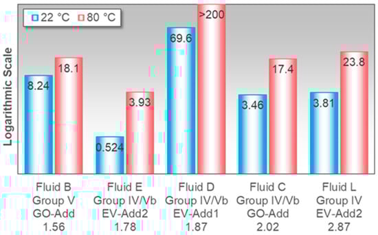
Figure 7.
Electric conductivity in nS/m. Fluid labels on the category axis include viscosity at 100 °C in mm2/s and some compositional information on base fluids and additives.
Additive chemistry has the biggest impact on overall conductivity, but base fluid chemistry and the interaction of base fluids with the additives are also significant contributors. Within the range of fluids discussed in this paper, temperature and fluid viscosity are of lesser significance, but still have a noticeable impact.
3. Results
3.1. Mechanical Testing
3.1.1. Introduction
Based on the test results described in the previous paragraphs, Fluids M, N, X, Y and Z have been selected for the next stage of testing. Fluids SYN and D served as references for the synchronizer and bearing tests, respectively.
3.1.2. Synchronizer Ring
Friction element performance in general is strongly connected to lubricating oil properties. In this work, the function of the SCHAEFFLER Synchronizer rings was tested with several ULV fluid formulations. Testing details and test results are listed in Table 3 and Table 4 below. With the two applied test procedures, the principal performance of the oils was determined. The Comb test (CoT) simulates shifts with variable load at higher temperatures. The aim is to achieve a secure shifting enabled by optimal friction behaviors. The Cold shift test (CST) operates with constant load at a low temperature; a minimum friction coefficient for secure locking conditions is required. The results show that the friction material has a stronger influence on performance than the here-tested oil formulations. With the carbon friction lining, all tested ULV-fluids showed acceptable friction performance.
Table 3.
Synchronizer test conditions.
Table 4.
Results of synchronizer function test.
3.1.3. Rolling Bearing
Rolling bearing performance was a major focus of the mechanical testing. Classical testing under boundary friction conditions via DIN 51819-3 [15] was complemented with a high-speed mixed friction test on the Schaeffler FE8 test rig with cylindrical roller thrust bearings (CRTB, see Figure 8 below), and a fatigue lifetime test with needle bearings (NKI 40/20, see Figure 9 below) at full fluid film conditions.
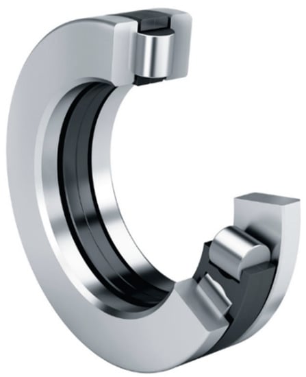
Figure 8.
CRTB.
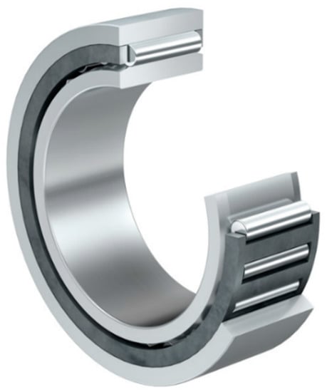
Figure 9.
NKI 40/20.
The test conditions of the high-speed mixed friction test “FE8-25” are listed in Table 5. With low viscous (LV) fluids, the test bearing also runs under mixed friction conditions at the given higher speed. Due to the bearing kinematics, this will lead to high sliding speeds in the slipping areas of rolling contact.
Table 5.
FE8-25 test conditions.
The results are shown in Figure 10. The reference oil Fluid D shows an acceptable performance. This is also visible in the pictures of the raceways after the test (Figure 11). At all bearing raceways from tests with a LV formulation, high wear is visible after short running times. The wear marks removed the original surface structure completely. In contrast to this, the addition of the reference oil is able to protect the bearings’ surface against wear. The pictures show the original bearing surface structure, with finishing marks still clearly visible.
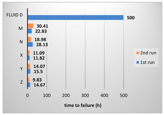
Figure 10.
Results of FE8-25 oil testing.
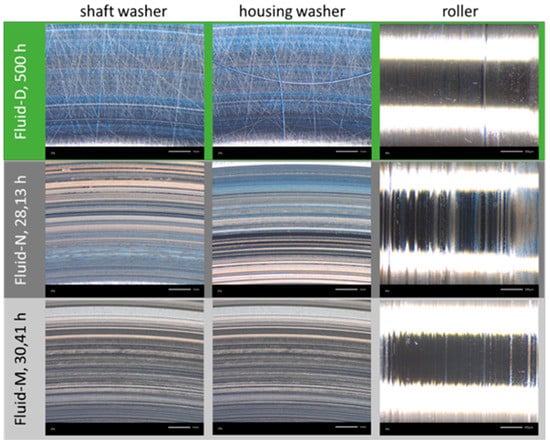
Figure 11.
CRTB raceways after test run FE8-25, examples.
Due to the high contact loads in the CRTB under the FE8-25 test conditions, the test is very harsh, with high requirements for the anti-wear properties of the lubricants. According to experience, other bearing types (i.e., deep groove ball bearings “DGBB”) are less wear-critical at this test stage. To determine the effects of low viscous fluids, the pitting test was run with needle bearings. The test conditions and specimen are listed in Table 6. The NKI 40/20 in this test is a radial-loaded bearing. The failure mode in the test was material fatigue—see Figure 12.
Table 6.
Rolling bearing pitting test conditions.
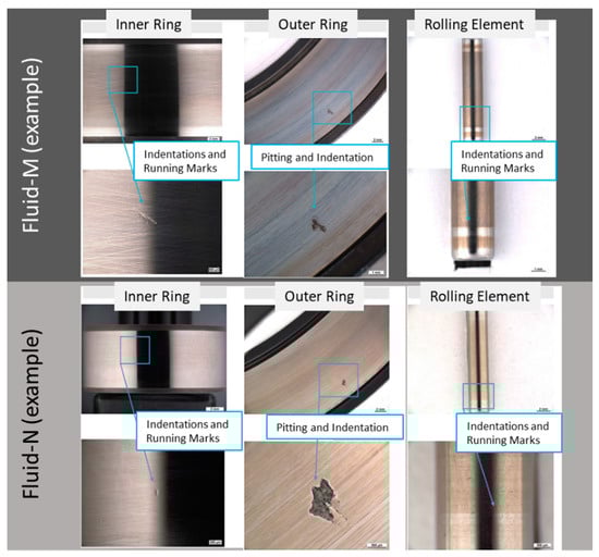
Figure 12.
Rolling bearing pitting test, failure examples.
Figure 13 provides the statistical results of the test runs, with Fluids N and M shown. The test runs with the “thinner” Fluid N, as expected, results in a shorter time to failure. In Figure 14, the comparative calculated bearing lifetime (Lhmr) via a Weibull distribution is displayed. The figure shows clearly that both oils lead to nearly the same “viscosity corrected” bearing lifetime. The real fatigue lifetime is approx. four times higher than calculated. Moreover, all statistical values are bigger than the calculated reference fatigue lifetime. This clearly indicates that satisfactory durability would be possible with these ULV fluids.
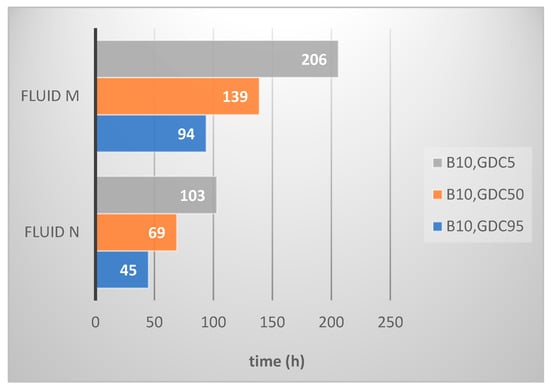
Figure 13.
Rolling bearing pitting test results, including confidence level (GDC5 = 5%; GDC50 = 50%; GDC95 = 95%).
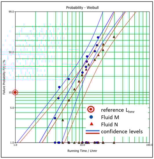
Figure 14.
Rolling bearing pitting test results normalized to Lhmr.
4. Summary and Conclusions
The impact of low viscosity fluids on transmission functionality and durability has been evaluated. Test fluids were based on a variety of Group IV and Group V base fluids, combined with different types of additives. Testing included typical drivetrain industry standards and selected transmission components. In addition, new properties specific to electric drivetrains were evaluated.
Based on the test results, lowering viscosity will certainly reduce degrees of freedom for transmission designers and fluid formulators alike. However, by careful selection of the base fluid and additives, it is still possible to achieve acceptable fluid performance, without compromising too much on component durability. In particular, critical rolling and sliding contacts can still operate securely with ULV fluids. These fluids will contribute to better efficiency not only by lower churning losses, but also via reduced energy consumption in associated components such as pumps.
Based on the insights generated in this project, ExxonMobil has developed an ultra-low viscosity fluid for the next generation of Schaeffler electric drive units. Transmission design and fluid formulation are in the final stages of gear box testing and field validation.
Author Contributions
Conceptualization, H.R.B.; Investigation, P.L.; Project administration, J.W.H.F. and S.K.; Writing—original draft, H.R.B. and J.W.H.F.; Writing—review & editing, S.K. and P.L. All authors have read and agreed to the published version of the manuscript.
Funding
This paper was not publicly founded.
Institutional Review Board Statement
Not applicable.
Informed Consent Statement
Informed consent was obtained from all subjects involved in the study.
Data Availability Statement
For more detailed data, please contact the authors.
Conflicts of Interest
The authors declare no conflict of interest.
References
- SAE J 306-Automotive Gear Lubricant Viscosity Classification; SAE International: Warrendale, PA, USA, 2019.
- Mayer, J. Fuel Economy Öle, FVV-Project 1014 Final Report, Heft 1041–2014; FVV: Frankfurt/Main, Germany, 2014. [Google Scholar] [CrossRef]
- Wittek, E. “Tribologisches Verhalten neuartiger Fuel Economy Öle in Wälzlagern” Abschlussbericht zum Vorhaben FVA 619 der Forschungsvereinigung Antriebstechnik e.V., Frankfurt/Main, Germany, 2014. Available online: https://fva-net.de/fileadmin/download/Infotagung/FVA_Info_Programm_2013.pdf (accessed on 2 December 2021).
- Gahagan, M. Lubricant Technology for Hybrid Electric Automatic Transmissions, SAE Technical Paper 2017-01-2358; SAE International: Warrendale, PA, USA, 2017. [Google Scholar] [CrossRef]
- Magyar, B.; Freise, R. Schmierstoffentwicklung für E-Antriebe: Der Teufel steckt im Detail. In Experten-Forum Powertrain: Reibung in Antrieb und Fahrzeug 2019; Liebl, J., Ed.; Springer Vieweg: Wiesbaden, Germany, 2020. [Google Scholar] [CrossRef]
- API 1509. Annex E-API Base Oil Interchangeability Guidelines for Passenger Car Engine Oils and Diesel Engine Oils, 20th ed.; API: Washington, DC, USA, 2021. [Google Scholar]
- API 1560. Lubricant Service Designations for Automotive Manual Transmissions, Manual Transaxles, and Axles, 8th ed.; API: Washington, DC, USA, 2013. [Google Scholar]
- CEC L-084-02. FZG Scuffing Load Carrying Capacity Test for High EP Oils; ISO: London, UK, 2004. [Google Scholar]
- FVA 2/IV 1997. Informationsblatt 2/IV: Einfluss des Schmierstoffes auf die Grübchenlebensdauer einsatzgehärteter Zahnräder im Einstufen- und im Lastkollektivversuch; Forschungsvereinigung Antriebstechnik: Frankfurt, Germany, 1997. [Google Scholar]
- CEC L-048-00. Oxidation Stability of Lubricating Oils Used in Automotive Transmissions by Artificial Ageing (Laboratory Test); SAE International: Warrendale, PA, USA, 2001. [Google Scholar]
- ASTM D130. Standard Test Method for Corrosiveness to Copper from Petroleum Products by Copper Strip Test; ASTM: West Conshohocken, PA, USA, 2019. [Google Scholar]
- ASTM E1269. Standard Test Method for Determining Specific Heat Capacity by Differential Scanning Calorimetry; ASTM: West Conshohocken, PA, USA, 2018. [Google Scholar]
- ASTM D7896. Standard Test Method for Thermal Conductivity, Thermal Diffusivity, and Volumetric Heat Capacity of Engine Coolants and Related Fluids by Transient Hot Wire Liquid Thermal Conductivity Method; ASTM: West Conshohocken, PA, USA, 2019. [Google Scholar]
- ASTM D2624. Standard Test Methods for Electrical Conductivity of Aviation and Distillate Fuels; ASTM: West Conshohocken, PA, USA, 2021. [Google Scholar]
- DIN51819. Testing of Lubricants-Mechanical-Dynamic Testing in the Roller Bearing Test Apparatus FE8-Part 3. In Test Method for Lubricating Oils-Applied Test Bearing: Axial Cylindrical Roller Bearing; Beuth Verlag: Berlin, Germany, 2016. [Google Scholar]
- ISO/TS16281. Rolling Bearings—Methods for Calculating the Modified Reference Rating Life for Universally Loaded Bearings (ISO/TS 16281:2008 + Cor 1:2009); Beuth Verlag: Berlin, Germany, 2017. [Google Scholar]
Publisher’s Note: MDPI stays neutral with regard to jurisdictional claims in published maps and institutional affiliations. |
© 2021 by the authors. Licensee MDPI, Basel, Switzerland. This article is an open access article distributed under the terms and conditions of the Creative Commons Attribution (CC BY) license (https://creativecommons.org/licenses/by/4.0/).