Investigation of the Structural, Mechanical and Tribological Properties of Plasma Electrolytic Hardened Chromium-Nickel Steel

 ,
,
Abstract
:1. Introduction
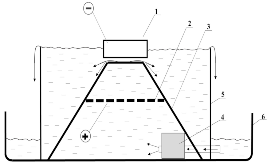
2. Materials and Methods
3. Results and Discussion
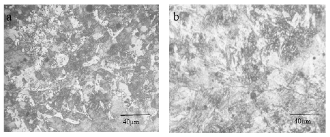
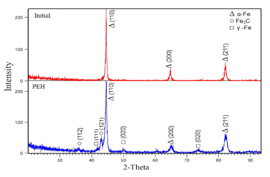
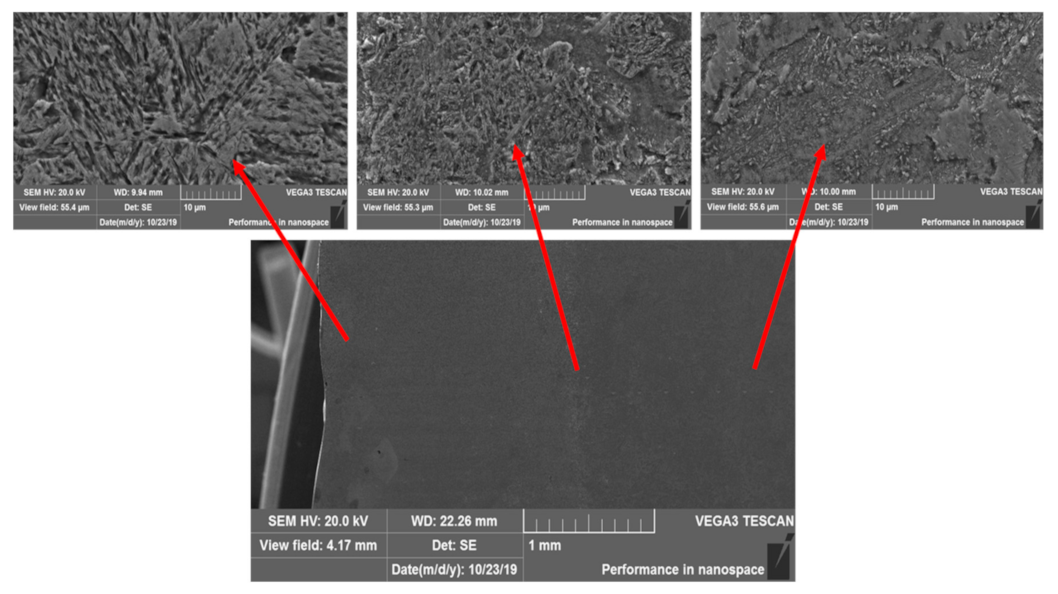
3.1. Structure and Morphology
3.2. Mechanical and Tribological Properties
4. Conclusions
- -
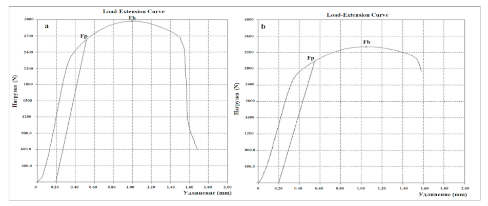
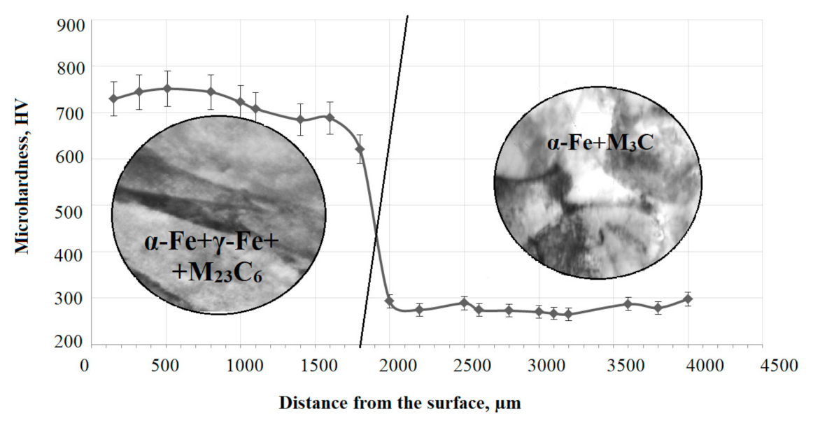
- Electrolytic-plasma hardening helps to improve the mechanical properties of 0.34C-1Cr-1Ni-1Mo-Fe steel; namely, the microhardness increases by 2.6 times, and the strength limit σB and yield strength σ0.2 increase to 835 MPa and 740 MPa, respectively, compared to those of the initial sample, which were 743 MPa and 648 MPa;
- -
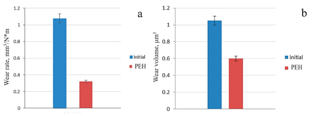
- The PEH improves the tribological properties of steel: the wear rate j of steel 0.34C-1Cr-1Ni-1Mo-Fe is equal to 0.32 mm3/Nm after the PEH; that is, 3.4 times less than the wear rate of the initial steel;
- -
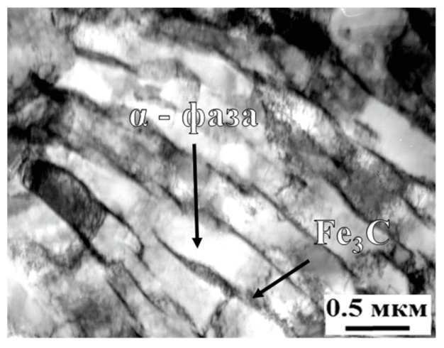
- The PEH leads to the formation of a modified layer consisting of an α′-phase (packet plate martensite), a γ′-phase, small particles of cementite M3C and uniformly arranged in the volume of the M23C6 carbide material;
- -
- Strengthening the microhardness and wear resistance of 0.34C-1Cr-1Ni-1Mo-Fe steel is associated with the formation of martensite, as well as the formation of a defective substructure.
Author Contributions
Funding
Conflicts of Interest
References
- Safonov, E.N. Plasma Hardening of Machine Parts: Monograph; NTI (branch) of UFU: Nizhny Tagil, Russia, 2014; p. 116. [Google Scholar]
- Bolshakova, M.Y.; Guzanov, B.N.; Migacheva, G.N. Probabilistic Method for Calculating the Durability of Heavy-Load Gears According to the Wear Criterion; Theory and technology of metallurgical production: Mezhregion, collection of scientific papers; Kolokoltsev, V.M., Ed.; Publishing house SEI HVE MSTU: Magnitogorsk, Russia, 2010; Volume 10, pp. 193–204. [Google Scholar]
- Medelyaev, N.A. Basic regularities of the processes of friction and wear in friction pairs of hydraulic machines. Vestn. Mashinostroeniya 2004, 9, 42–47. [Google Scholar]
- Yeliseev, Y.S.; Krymov, V.V.; Nezhurin, I.P.; Novikov, V.S.; Ryzhov, N.M. Production of Gear Wheels of Gas Turbine Engines; Higher school: Moscow, Russia, 2001; p. 495. [Google Scholar]
- Kalashnikov, A.S.; Morgunov, Y.A.; Kalashnikov, P.A. Modern Methods of Processing Gears; Publishing house Spectr: Moscow, Russia, 2012; p. 238. [Google Scholar]
- Samotugin, S.S. Plasma micro -and nanostructuring of the surface of tool steels. Reinf. Technol. Coat. 2013, 29–37. [Google Scholar]
- Korotkov, V.A. Plasma Hardening of the Surface; STI (Branch) of UFU: Nizhny Tagil, Russia, 2012; p. 64. [Google Scholar]
- Stavrev, D.S.; Kaputkina, L.M.; Kirov, S.K.; Shamonin, Y.V.; Prokoshkina, V.G. Influence of plasma-arc processing on structural transformations and surface hardening of carbon and alloy steels. MiTOM 1996, 16–19. [Google Scholar]
- Stepanova, T.Y. Technologies of Surface Hardening of Machine Parts: Tutorial; Ivanovo State Chemical-Technological University: Ivanovo, Russia, 2009; p. 64. [Google Scholar]
- Zhurerova, L.G.; Rakhadilov, B.K.; Popova, N.A.; Kylyshkanov, M.K.; Buranich, V.V.; Pogrebnjak, A.D. Effect of the PEN/C surface layer modification on the microstructure, mechanical and tribological properties of the 30CrMnSiA mild-carbon steel. J. Mater. Res. Technol. 2020, 9, 291–300. [Google Scholar] [CrossRef]
- Suminov, I.V.; Belkin, P.N.; Epelfeld, A.V.; Lyudin, V.; Krit, B.; Borisov, A. Plasma-Electrolytic Modification of the Surface of Metals and Alloys; Suminov, I.V., Ed.; Technosphere: Moscow, Russia, 2011; p. 464. [Google Scholar]
- Devices and Methods of Physical Metallurgy; Weinberg, F. (Ed.) Mir: Moscow, Russia, 1973; Volume 1, p. 427. [Google Scholar]
- Gorelik, S.S.; Skakov, Y.A.; Rastorguev, L.N. X-ray and Electron-Optical Analysis; MISIS: Moscow, Russia, 2002; p. 360. [Google Scholar]
- Grigorevich, V.K. Hardness and Microhardness of Metal; Nauka: Moscow, Russia, 1976; p. 230. [Google Scholar]
- Zarchi, M.K.; Shariat, M.H.; Dehghan, S.A.; Solhjoo, S. Characterization of nitrocarburized surface layer on AISI 1020 steel by electrolytic plasma processing in an urea electrolyte. J. Mater. Res. Technol. 2013, 2, 213–220. [Google Scholar] [CrossRef] [Green Version]
- Senatore, A.; Risitano, G.; Scappaticci, L.; D’Andrea, D. Investigation of the Tribological Properties of Different Textured Lead Bronze Coatings under Severe Load Conditions. Lubricants 2021, 9, 34. [Google Scholar] [CrossRef]
- Duradji, V.N. Thermochemical treatment of metals with heating in electrolytic plasma. Technol. Surf. Treat. 2010, 6, 59–61. [Google Scholar]
- Rakhadilov, B.K.; Buranich, V.V.; Satbayeva, Z.A.; Sagdoldina, Z.B.; Kozhanova, R.S.; Pogrebnjak, A.D. The cathodic electrolytic plasma hardening of the 20Cr2Ni4A chromium-nickel steel. J. Mater. Res. Technol. 2020, 9, 6969–6976. [Google Scholar] [CrossRef]
- Rakhadilov, B.K.; Satbayeva, Z.; Baizhan, D. Effect of electrolytic-plasma surface strengthening on the structure and properties of steel 40 kHN. In Proceedings of the METAL 2019—28th International Conference on Metallurgy and Materials, Brno, Czech Republic, 22–24 May 2019; pp. 950–955. [Google Scholar]
- Qiu, X.; Wei, X.; Xu, X.; Xu, W.; Zhu, M. Dependence of fretting wear resistance on microstructural features of alloyed steels. Tribol. Int. 2019, 137, 39–45. [Google Scholar] [CrossRef]
- Kozlov, E.; Popova, N.; Zhurerova, L.; Nikonenko, E.; Kalashnikov, M.; Skakov, M. Structural and Phase Transformations in 0.3C-1Cr-1Mn-1Si-Fe Steel after Electrolytic Plasma Treatment. In AIP Conference Proceedings; AIP Publishing LLC: Melville, NY, USA, 2016; Volume 1783, p. 20112. [Google Scholar]


| Material | Characteristics | ||||||||
|---|---|---|---|---|---|---|---|---|---|
| Phase Composition | Hµ, MPa | f | j, 10−4 mm3/Nm | V, µm3 | σB, MPa | σ0.2, MPa | H, GPa | E, GPa | |
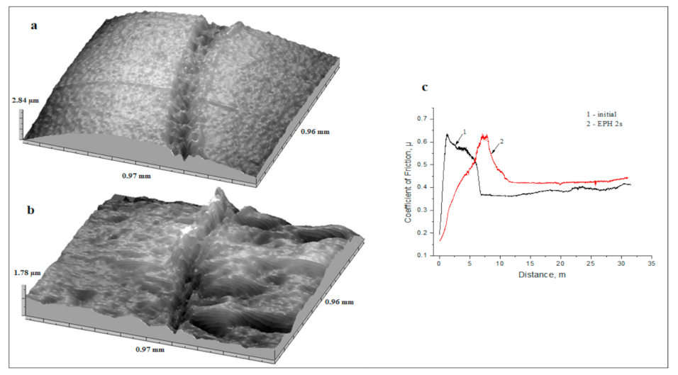
| Initial state | α-phase | 2830 | 0.44 | 1.08 | 1.05 | 743 | 648 | 2.88 | 242.33 |
| After PEH, 2 s | α′-phase, γ-phase, M3C, M23C6 | 7420 | 0.37 | 0.32 | 0.6 | 835 | 740 | 8.12 | 296.25 |
Publisher’s Note: MDPI stays neutral with regard to jurisdictional claims in published maps and institutional affiliations. |
© 2021 by the authors. Licensee MDPI, Basel, Switzerland. This article is an open access article distributed under the terms and conditions of the Creative Commons Attribution (CC BY) license (https://creativecommons.org/licenses/by/4.0/).
Share and Cite
Rakhadilov, B.; Seitkhanova, A.; Satbayeva, Z.; Yerbolatova, G.; Icheva, Y.; Sagdoldina, Z. Investigation of the Structural, Mechanical and Tribological Properties of Plasma Electrolytic Hardened Chromium-Nickel Steel. Lubricants 2021, 9, 108. https://doi.org/10.3390/lubricants9110108
Rakhadilov B, Seitkhanova A, Satbayeva Z, Yerbolatova G, Icheva Y, Sagdoldina Z. Investigation of the Structural, Mechanical and Tribological Properties of Plasma Electrolytic Hardened Chromium-Nickel Steel. Lubricants. 2021; 9(11):108. https://doi.org/10.3390/lubricants9110108
Chicago/Turabian StyleRakhadilov, Bauyrzhan, Ainur Seitkhanova, Zarina Satbayeva, Gulnara Yerbolatova, Yulianna Icheva, and Zhuldyz Sagdoldina. 2021. "Investigation of the Structural, Mechanical and Tribological Properties of Plasma Electrolytic Hardened Chromium-Nickel Steel" Lubricants 9, no. 11: 108. https://doi.org/10.3390/lubricants9110108
APA StyleRakhadilov, B., Seitkhanova, A., Satbayeva, Z., Yerbolatova, G., Icheva, Y., & Sagdoldina, Z. (2021). Investigation of the Structural, Mechanical and Tribological Properties of Plasma Electrolytic Hardened Chromium-Nickel Steel. Lubricants, 9(11), 108. https://doi.org/10.3390/lubricants9110108