Article

Analytical Elastostatic Contact Mechanics of Highly-Loaded Contacts of Varying Conformity

by
Patricia M. Johns-Rahnejat
1,
Nader Dolatabadi
2,* and
Homer Rahnejat
1
1
School of Engineering, University of Central Lancashire, Preston PR1 2XQ, UK
2
Wolfson School of Mechanical, Electrical and Manufacturing Engineering, Loughborough University, Loughborough LE11 3TU, UK
*
Author to whom correspondence should be addressed.
Lubricants 2020, 8(9), 89; https://doi.org/10.3390/lubricants8090089
Submission received: 30 July 2020 / Revised: 29 August 2020 / Accepted: 31 August 2020 / Published: 2 September 2020

Abstract

:
In applications requiring high load carrying capacity, conforming contacting pairs with a relatively large contact footprint are used. These include circular arc, Novikov, and Wildhaber gears found, for example, in helicopter rotors. Closely conforming contacts also occur in many natural endo-articular joints, such as hips, or their replacement arthroplasty. The main determining factors in contact fatigue are the sub-surface shear stresses. For highly loaded contacts, classical Hertzian contact mechanics is used for many gears, bearings, and joints. However, the theory is essentially for concentrated counterforming contacts, where the problem is reduced to a rigid ellipsoidal solid penetrating an equivalent semi-infinite elastic half-space. Applicability is limited though, and the theory is often used inappropriately for contacts of varying degrees of conformity. This paper presents a generic contact mechanics approach for the determination of sub-surface stresses, which is applicable to both highly conforming as well as concentrated counterforming contacts. It is shown that sub-surface shear stresses alter in magnitude and disposition according to contact conformity, and lead to the different modes of fatigue failure noted in practice.

Graphical Abstract

1. Introduction

Conforming gear pairs are used in highly loaded applications, for example, the Novikov gears of the final drive of helicopter gearboxes and some turboprops [1,2]. In such gearing systems, convex-concave teeth pair geometry of a high degree of conformity (with very small radius difference, δR, as shown in Figure 1) is used in order to maximize the contact footprint area and thus the load carrying capacity [3]. It is quite clear that the footprint contact dimensions, typically shown in Figure 2a, are comparable with the local radii of curvature of the contacting teeth pair, R 1 and R 2 ,   at any instant of time as shown in Figure 2b. Therefore, the semi-infinite elastic solid assumption underlying classical Hertzian theory cannot be upheld [4]. The same can also be true of some counterformal gear teeth pairs, where Hertzian contact mechanics is often erroneously used in literature. However, carrying out 3D contact mechanics analysis is very time consuming, particularly for a gearing pair, where applied load during a meshing cycle and kinematic conditions are altered instantaneously. In such cases, the geometrical and kinematic conditions are obtained through tooth contact analysis [5,6,7,8]. Clearly, an analytical model is preferable as a first approach if 2D contact analysis can be assumed. Generically, a conforming contact is represented by a disc of radius R 1   residing in a cavity of radius R 2 (Figure 2c), where R 1 and R 2   are very close in dimension. In addition, the contact width of the disc is assumed to be very large (infinite) compared with the radii R 1 and R 2 .
The onset of fatigue spalling determines the useful life of gearing pairs [9,10,11], so an accurate prediction of sub-surface shear stresses is the main aim. For hard and brittle surfaces, maximum shear stress is the most important according to the Tresca failure criterion, whereas for ductile solids, particularly bearings and gears, the reversing orthogonal shear stresses are the main determining factors of gear life [4,12].
There has been a significant volume of research concerning the evaluation of sub-surface stresses, mostly for counterformal concentrated contacts with the first solutions reported by Huber [13] and Huber and Fuchs [14]. Lyman [15] was the first to study the reversing orthogonal shear stresses in rolling contacts, with Poritsky [16] investigating the effect of reversing stressing in gears and locomotive wheels. Johnson [17,18] provides a comprehensive review of the early investigations as well as the fundamental aspects of contact mechanics of counterformal contacts. Other representative solutions for counterformal idealized elastic line contact under dry contact conditions have also been reported [19,20,21], some for inhomogeneous solids [22] and some for layered bonded solids such as coated surfaces [23,24]. Other solutions have included lubricated contact conditions subjected to an elastohydrodynamic regime of lubrication [25,26,27,28]. For point contact conditions, comprehensive 3D sub-surface stress evaluation for the application of any arbitrary pressure distribution for the contact of counterforming pairs was reported by Johns-Rahnejat and Gohar [29] and Czyzewski [30]. Other 3D analyses are also provided by Sackfield and Hills [31] for a Hertzian ellipsoidal pressure distribution, and with the inclusion of tangential traction [32]. However, as already noted, 3D solutions are computationally very intensive, particularly for conforming solids with a large footprint contact area. This paper provides a 2D solution for sub-surface stresses in contacts of varying degrees of conformity. It is analytical and applicable to a range of contacting elastic solids, such as discs, circular arc, and Novikov gears, as well as counterformal semi-infinite solids where the Hertzian pressure distribution is used.

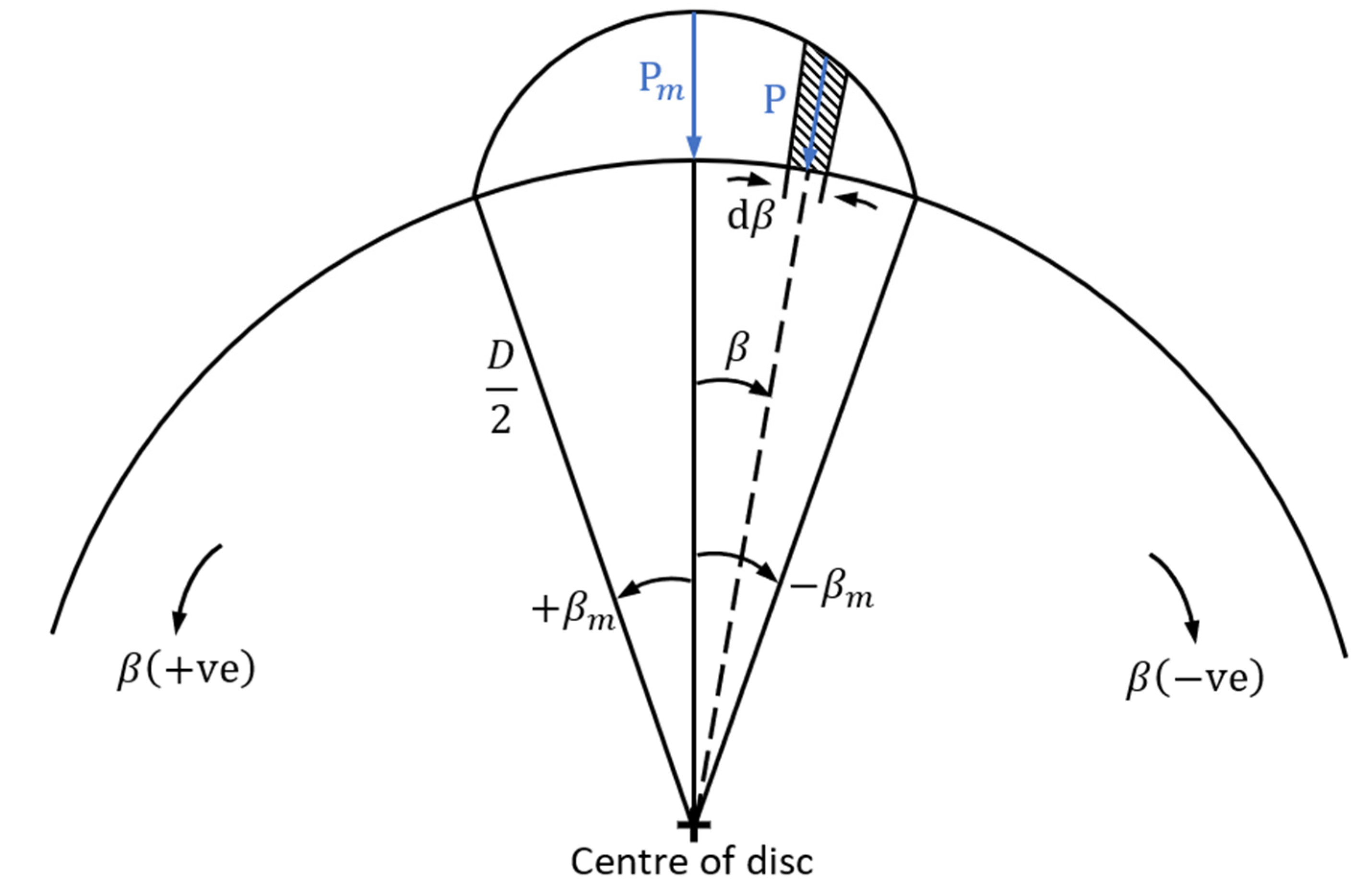
2. Determination of 2D Sub-Surface Stress Field

2.1. Case of Non-Conforming Semi-Infinite Solids

For non-conforming gear teeth pairs, one may assume the equivalent contact of an ellipsoidal rigid solid of reduced radius, R against a semi-infinite elastic half-space of equivalent (reduced) elastic modulus, E * as in the classical Hertzian theory, where:
1 R = 1 R 1 + 1 R 2 ,
E * = E 1 ϑ 2 ,
where, Equation (2) gives the plane strain elastic modulus for contacting solids made of the same material with Young’s modulus of elasticity, E and Poisson’s ratio, ϑ .
For the general case of 2D stresses into the bulk of a semi-infinite solid, a parabolic pressure distribution is assumed, which closely approximates the 2D elliptical Hertzian pressure profile, as noted by many authors such as Love [33] and Muskhelishvili [34]:
p = p m ( 1 x 1 2 a 2 ) ,
where, p is pressure, p m is the maximum pressure of a parabolic pressure distribution formed over the contact length of: a x 1 a (a is the semi-half width of the thin Hertzian rectangular strip contact footprint [4,18]). It should be noted that the current analysis considers a dry frictionless contact of elastic bodies subjected to a Hertzian pressure distribution. In practice, the contact of elastic solids is often rough and invariably lubricated. Therefore, for highly loaded contacts under elastohydrodynamic regime of lubrication, the pressure distribution deviates from that of Hertzian, including an inlet rising trail and a pressure spike in the vicinity of the contact exit as measured using micro-miniature pressure transducers [35,36]. Sub-surface stress fields under these measured conditions were reported [29]. Rolling contact fatigue cracking can also occur due to elastohydrodynamic squeeze effect [37].
Returning to direct and shear stresses in an element within the bulk of a semi-infinite dry frictionless elastic half-space (Figure 3), it follows that [18]:
d σ x = 2 p d x 1 π ( x x 1 ) 2 z { ( x x 1 ) 2 + z 2 } 2 ,
d σ z = 2 p d x 1 π z 3 { ( x x 1 ) 2 + z 2 } 2 ,
d τ z x = 2 p d x 1 π ( x x 1 ) 2 z 2 { ( x x 1 ) 2 + z 2 } 2 ,
The chosen parabolic pressure distribution allows analytical integration of the above equations. Now replacing for parabolic pressure distribution from Equation (3), and using the stated non-dimensional terms, the 2D sub-surface stress field for a semi-infinite solid is obtained as:
σ ¯ x ¯ = 2 z ¯ 1 1 ( x ¯ x ¯ 1 ) 2 ( 1 x ¯ 2 ) { ( x ¯ x ¯ 1 ) 2 + z ¯ 2 } 2 d x ¯ 1 ,
σ ¯ z ¯ = 2 z ¯ 3 1 1 ( 1 x ¯ 2 ) { ( x ¯ x ¯ 1 ) 2 + z ¯ 2 } 2 d x ¯ 1 ,
τ ¯ z x ¯ = 2 z ¯ 2 1 1 ( x ¯ x ¯ 1 ) ( 1 x ¯ 2 ) { ( x ¯ x ¯ 1 ) 2 + } 2 d x ¯ 1 ,
The non-dimensional terms are:
x ¯ = x a ,   z ¯ = z a ,   x ¯ 1 = x 1 a ,   σ ¯ x ¯ = π σ x p m ,   σ ¯ z ¯ = π σ z p m ,   τ ¯ z x ¯ = π τ z x p m   ,
Solution of Equations (7)–(9) leads to the 2D sub-surface stress field for the case of non-conforming contact of semi-infinite elastic solids, subjected to a normal applied parabolic pressure distribution, approximating a Hertzian elliptical pressure distribution. Solution to this problem is provided for the case of an infinite line contact by Johnson [18] and other researchers thereafter [19,20,21].
The solution to Equations (7)–(9) is provided in [4,18]. Here, Figure 4 shows the sub-surface stress field along the z ¯ -axis into the depth of the semi-infinite elastic half-space at the position of the maximum pressure ( x ¯ = 0 ) for a parabolic distribution (as in Figure 3). The maximum shear stress is: τ ¯ m a x = | σ ¯ x ¯ σ ¯ z ¯ | 2 , where the stresses in the x ¯ and z ¯ directions are the principal stresses. The maximum shear stress is a determining factor for sub-surface inelastic failure, particularly for hard and brittle substrates. For ductile material the cyclic reversing orthogonal shear stress τ ¯ z x ¯   is the determining factor [4,12,14].

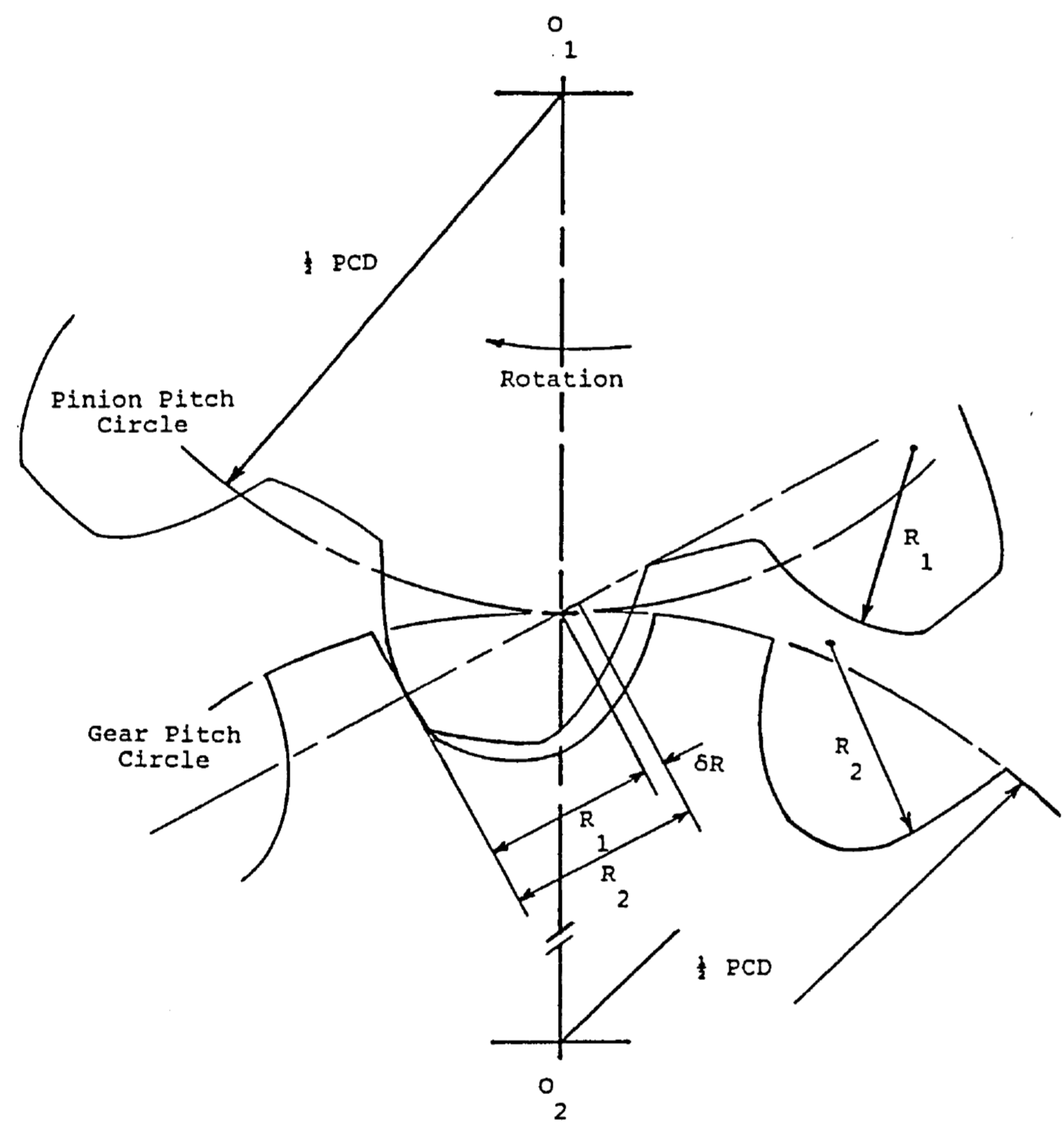
2.2. Case of Conforming Elastic Solids

For conforming contacts, the area (or in the case of 2D analysis, the arc length) of contact can be comparable to the dimensions (contact radii) of mating surfaces (an example is the circular arc gear teeth in Figure 1). As a result, a Hertzian-type contact cannot necessarily be assumed and, therefore, an approximate parabolic pressure distribution as in Equation (3) cannot be used since the semi-half-width of the contact, a does not follow the Hertzian theory. In such cases, one can use the following assumed parabolic pressure distribution:
p = p m k β 2 ,
where k is an arbitrary constant and β is any location within the arc of contact, measured from the position of the maximum pressure, p m . The value of k can be obtained by applying the boundary condition: p = 0 ,     β = β m , where 2 β m is the total arc length of the applied parabolic pressure distribution over a disc (Figure 5), representing an instantaneous conforming contact of a disc (e.g., representing a convex tooth in 2D) within a cavity (e.g., a concave tooth). A disc-in-cavity is the general case of a 2D conforming contact (Figure 2c), where the degree of conformity is affected by the arc length of contact, 2 β m . Applying the above-stated boundary condition:
k = p m β m 2 ,
Thus:
p = p m { 1 ( β β m ) 2 } ,
Muskhelishvili [34] showed that stresses in a disc at a point x , z with respect to the direction β of an applied line load, W are obtained as:
σ z = 2 W π { ( D 2 z ) 3 [ x 2 + ( D 2 z ) 2 ] 2 + ( D 2 + z ) 3 [ x 2 + ( D 2 + z ) 2 ] 2 } 2 W π D ,
σ x = 2 W π { x 2 ( D 2 z ) [ x 2 + ( D 2 z ) 2 ] 2 + x 2 ( D 2 + z ) [ x 2 + ( D 2 + z ) 2 ] 2 } 2 W π D ,
τ z x = 2 W π { x ( D 2 z ) 2 [ x 2 + ( D 2 z ) 2 ] 2 + x ( D 2 + z ) 2 [ x 2 + ( D 2 + z ) 2 ] 2 } ,
These stresses can be made applicable for a parabolic pressure distribution as in Equation (13) by making the substitution:
W = D p m β m 2 1 + 1 [ 1 ( β β m ) 2 ] d β ,
Substituting Equations (13) and (17) into Equations (14)–(16) yields:
σ ¯ z ¯ = β m 1 + 1 ( 1 β * 2 ) { ( 1 2 z ¯ cos β m β * ) [ cos 2 β m β * ( 1 2 z ¯ cos β m β * ) 2 z ¯ sin β m β * sin 2 β m β * ( 1 2 z ¯ cos β m β * ) + ( z ¯ ) 2 sin 4 β m β * ] / [ ( z ¯ ) 2 sin 2 β m β * + ( 1 2 z ¯ cos β m β * ) 2 ] 2 + ( 1 2 +   z ¯ cos β m β * ) [ cos 2 β m β * ( 1 2 + z ¯ cos β m β * ) 2 + z ¯ sin β m β * sin 2 β m β * ( 1 2 + z ¯ cos β m β * ) + ( z ¯ ) 2 sin 4 β m β * ] / [ ( z ¯ ) 2 sin 2 β m β * + ( 1 2 + z ¯ cos β m β * ) 2 ] 2 1 } d β * ,
σ ¯ x ¯ = β m 1 + 1 ( 1 β * 2 ) { ( 1 2 z ¯ cos β m β * ) [ sin 2 β m β * ( 1 2 z ¯ cos β m β * ) 2 + z ¯ sin β m β * sin 2 β m β * ( 1 2 z ¯ cos β m β * ) + ( z ¯ ) 2 sin 2 β m β * cos 2 β m β * ] / [ ( z ¯ ) 2 sin 2 β m β * + ( 1 2 z ¯ cos β m β * ) 2 ] 2 + ( 1 2 + z ¯ cos β m β * ) [ sin 2 β m β * ( 1 2 + z ¯ cos β m β * ) 2 + z ¯ sin β m β * sin 2 β m β * ( 1 2 + z ¯ cos β m β * ) + ( z ¯ ) 2 sin 2 β m β * cos 2 β m β * ] / [ ( z ¯ ) 2 sin 2 β m β * + ( 1 2 + z ¯ cos β m β * ) 2 ] 2 1 } d β * ,
τ ¯ z x ¯ = β m 1 + 1 ( 1 β * 2 ) { ( 1 2 z ¯ cos β m β * ) [ 1 2 sin 2 β m β * ( 1 2 z ¯ cos β m β * ) 2 + z ¯ sin β m β * cos 2 β m β * ( 1 2 z ¯ cos β m β * ) 1 2 ( z ¯ ) 2 sin 2 β m β * sin 2 β m β * ] / [ ( z ¯ ) 2 sin 2 β m β * + ( 1 2 z ¯ cos β m β * ) 2 ] 2 + ( 1 2 + z ¯ cos β m β * ) [ 1 2 sin 2 β m β * ( 1 2 + z ¯ cos β m β * ) 2 z ¯ sin β m β * cos 2 β m β * ( 1 2 + z ¯ cos β m β * ) 1 2 ( z ¯ ) 2 sin 2 β m β * sin 2 β m β * ] / [ ( z ¯ ) 2 sin 2 β m β * + ( 1 2 + z ¯ cos β m β * ) 2 ] 2 1 } d β * ,
where the non-dimensional stresses are those stated in relationships (10), and the other non-dimensional terms are:
β * = β β m   and   z ¯ = z D ,
Note the different definition for z ¯ in the generic case here, as opposed to that for a parabolic pressure distribution as an approximation to an elliptical Hertzian pressure distribution for a semi-infinite solid used in relationships (10).
Before proceeding with the results of the generic methodology expounded here, it is important to undertake a validation study. The appropriate approach is to validate the methodology against a classical universally acknowledged solution, such as the sub-surface stress field for a semi-infinite elastic half space subjected to Hertzian conditions (such as that shown in Figure 4). Clearly, as the value of β m decreases the contact conformity diminishes. Therefore, with the generic formulation here and a half-contact arc of β m = 0.02 rad ( 1.15 ° ), the conditions tend to the case of a non-conforming contact. Figure 6 shows that the maximum shear stress for both cases of a semi-infinite (non-conforming) contact and that predicted by the generic methodology agree very closely. Furthermore, the depth at which the absolute maximum shear stress occurs is identical. Clearly as the extent of contacting arc, 2 β m , increases, a larger divergence occurs between the results of the two methodologies with a greater degree of conformity.
It should be noted that the maximum shear stress and depths of contact are converted for the case of the generic method to that for the semi-infinite Hertzian condition, using their appropriate non-dimensional terms in (10) and (21).

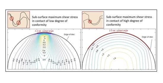
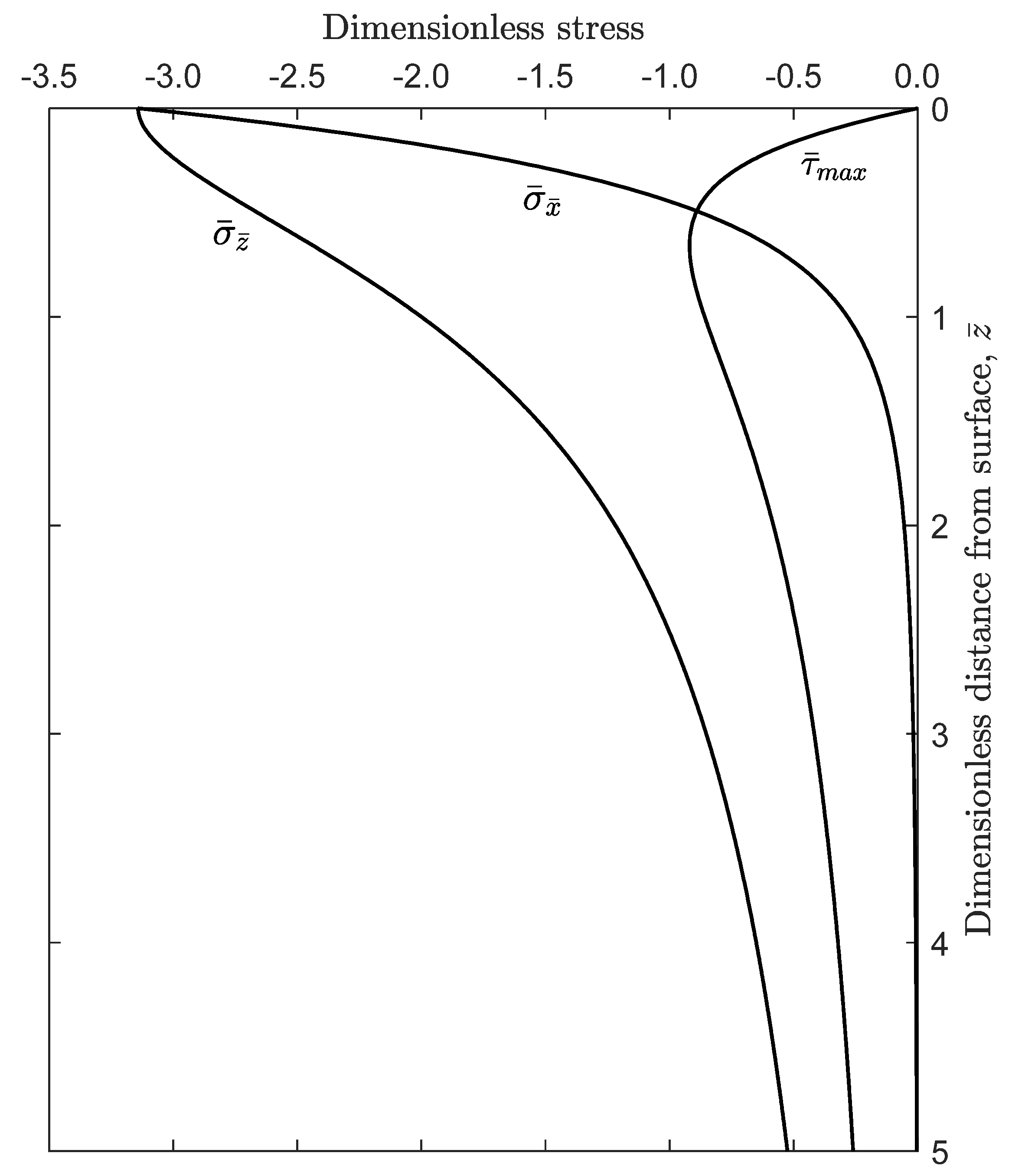
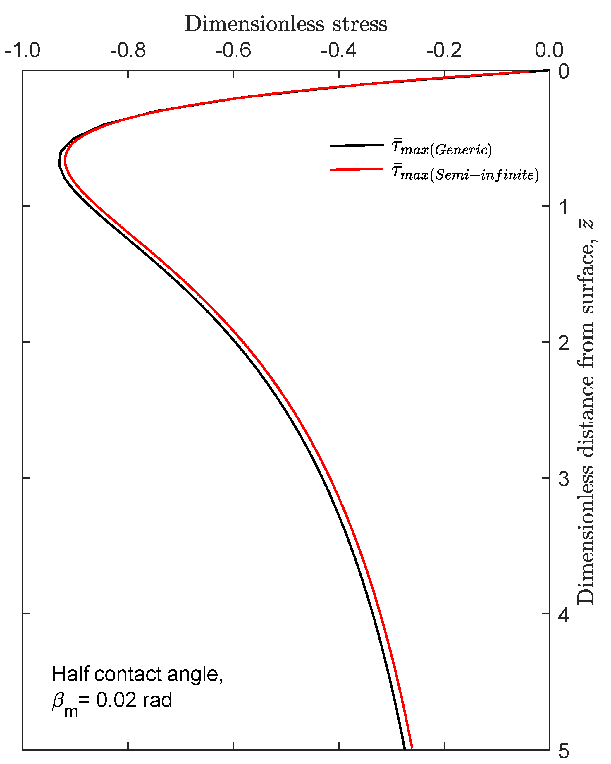
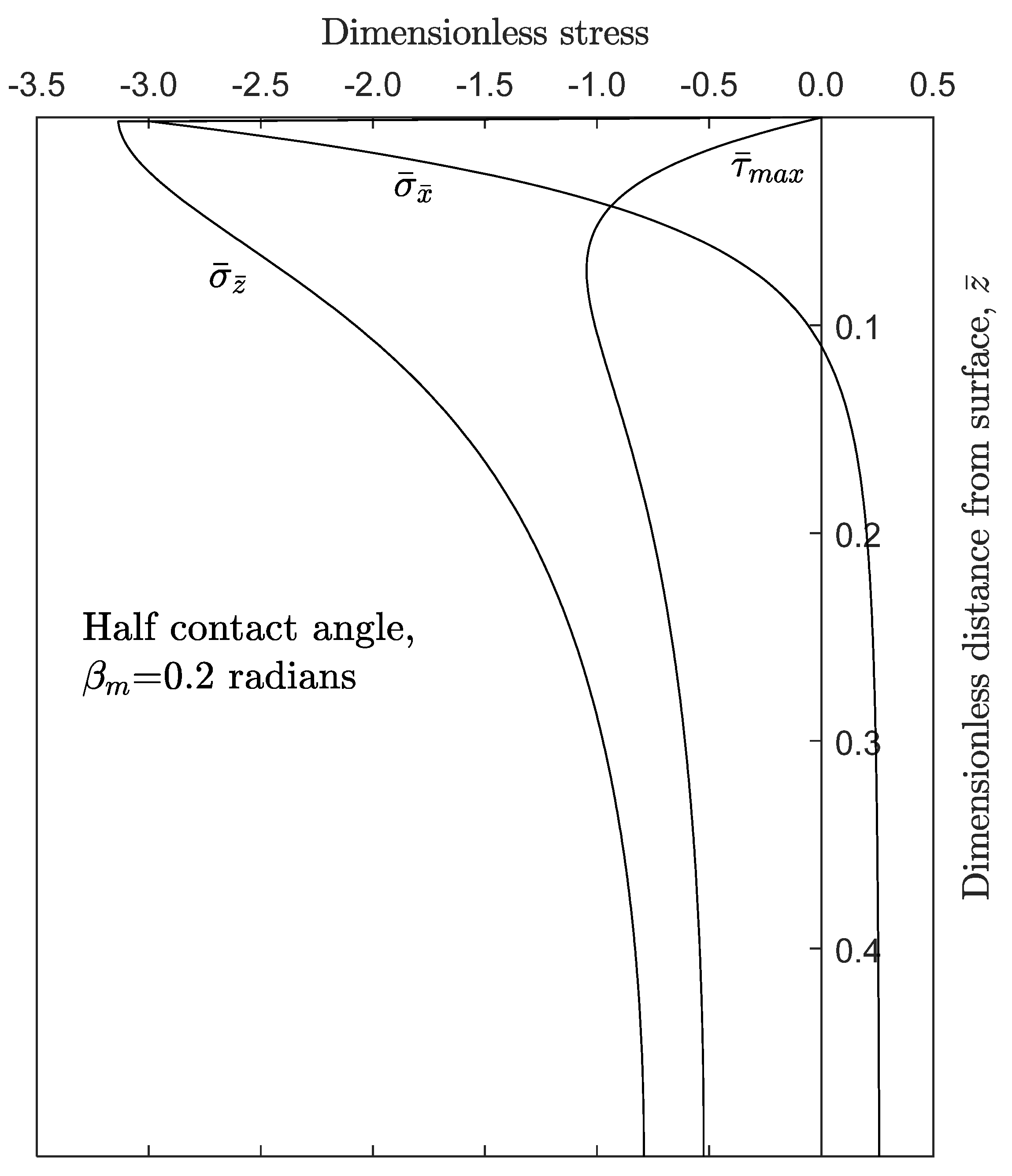
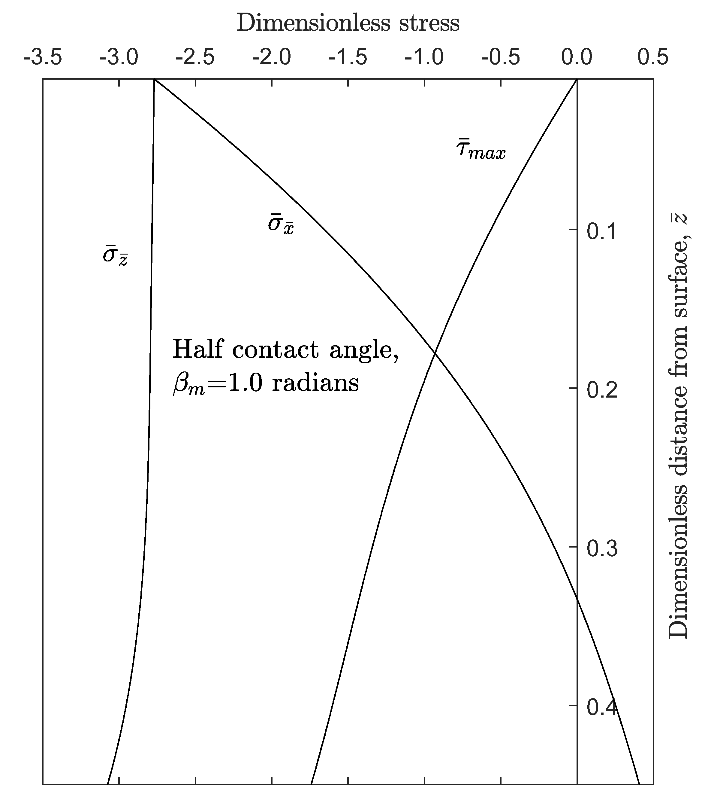
3. Results and Discussion

As already noted, Equations (18)–(20) provide the variation of the sub-surface stress field along the z ¯ -axis, when x ¯ = 0 . In this case, the following substitutions are made in Equations (14)–(16):
x = z sin β ,           z = z cos β ,
For any applied parabolic pressure distribution for any given contacting arc, 2 β m   , symmetric about the position x ¯ = 0 , the shear stress variation along the z ¯ -axis is: τ ¯ z x ¯ = 0 . In this case, the stresses σ ¯ z ¯ and σ ¯ x ¯ are the principal stresses. The maximum sub-surface shear stress is obtained as:
τ ¯ m a x = 1 2 | σ ¯ z ¯ σ ¯ x ¯ | ,
Figure 4 shows the sub-surface stress field for the case of counterformal contact, where it is already well-established that the maximum value of τ ¯ m a x = 0.9 . This occurs at a depth of z = 0.78 a , for a Hertzian elliptical pressure distribution for a homogeneous, isotropic semi-infinite elastic half-space. For a small contact angle using the generic methodology of a disc-in-a cavity expounded here, a contact with very low degree of conformity would result. In fact, very similar results as those in Figure 4 are obtained for β m = 0.02 rad ( 1.15 ° ) (as shown in Figure 6). For larger arcs of contact, the sub-surface stresses diverge from the semi-infinite assumption of the classical Hertzian theory. However, it should be noted that in many practical gearing cases the value of β m 0.1 rad ( 5.7 ° ) . Figure 7 and Figure 8 show the same sub-surface stress field components as the arc of contact is increased. As the arc of contact extends further, the contact becomes progressively more conforming. It can be clearly seen that the maximum shear stress moves inwards to the bulk of the material. The maximum principal stress, σ ¯ z ¯ tends to uniformity within the layers of bulk material and the minimum principal stress, σ ¯ x ¯   begins to diminish. Consequently, there is a gradual increase in the magnitude of shear stress as it moves further into the depth of the solid. The implication is that for counterformal concentrated contacts the near-surface maximum shear stress can lead to failure by micro-pitting, which is observed in many highly loaded involute spur and helical gears [9,10,11]. For circular arc and Novikov gearing with a greater degree of conformity, teeth-pair inelastic deformation can occur in the depth of the material, followed by crack initiation and propagation to the contacting surface as shown in [4,9,10,11,20] among other contributions. In all cases, the shear stress must reach approximately τ m a x 0.3 p m in the presence of small inclusions/pits or cavities in the bulk solid for any inelastic deformation to take place.
Now using Equations (14)–(16), but this time using the substitutions in (24) as well as Equation (17), after non-dimensionalisation, the entire sub-surface stress contours can be obtained:
z = z c o s β + x s i n β   and   x = z s i n β + x c o s β
There is no orthogonal shear stress along the z ¯ -axis, so the maximum shear stress is given by Equation (23). Elsewhere in the sub-surface stress field; τ ¯ z x ¯ 0 . Hence, the maximum shear stress contour for the domain ( x ¯ , z ¯ ) is obtained as:
τ ¯ m a x = 1 2 { ( σ ¯ z ¯ σ ¯ x ¯ ) 2 + τ ¯ z x ¯ 2 } 1 2 ,
Figure 9 and Figure 10 show the entire sub-surface maximum shear stress contour. The same observations as before can be made, that with an increasing degree of conformity (i.e., an increasing value of β m ), maximum shear stresses retreat into the depth of the contacting solids. This is evident when comparing the contours in Figure 9 and Figure 10. With reduced contact conformance there are more concentrated shear stresses near the surface. In all cases, the maximum shear stresses occur along the z ¯ -axis.

4. Concluding Remarks

A generic analytical contact mechanics methodology is presented to determine the sub-surface shear stress field, which is often the limiting factor in the structural reliability of many highly loaded contacts. The methodology is applicable to contacts of different degrees of conformity, including concentrated highly loaded counterformal contacts, where the problem is usually reduced to an equivalent ellipsoidal rigid solid of revolution contacting an equivalent semi-infinite elastic half-space, in line with the classical Hertzian theory. When the degree of conformity increases, as in many applications, the assumptions of the classical Hertzian theory cannot be upheld. In these cases, often complex 3D contacting geometry is used to determine the contact footprint, followed by finite element or finite difference solution of a discretized sub-surface domain. This is a very time consuming and computationally intensive undertaking. When a 2D domain may be assumed as a good approximation to the overall conditions, then a generic analytical and time efficient methodology is developed and highlighted in this paper.
The analysis shows that with low degree of contact conformity, represented by a small arc of contact, the results obtained are in line with the counterformal concentrated contact as represented by the classical Hertzian theory. Many applications are adequately represented by the Hertzian theory, such as cam-tappet, cam-roller, ball and rolling element bearings-to-raceway grooves, and involute spur, helical, and hypoid gear pairs. However, as the degree of conformity increases the sub-surface stress field deviates from the semi-infinite elastic half-space assumption at the heart of Hertzian theory. For these cases, the more generic methodology presented in this paper applies. Applications such as roller-in-socket, circular arc and Wildhaber-Novikov gears fall into the category of highly loaded conforming contacts. Furthermore, the methodology highlighted here can be used for any material combinations, which may be of lower elastic modulus, thus subject to larger strains than those at the core of the Hertzian theory.
The results show that for hard materials with a low degree of contact conformity, failure due to sub-surface stresses in the presence of material voids, inclusions, and cavities occurs when the maximum shear stress is near the contacting surface. These failures will be in the form of micro-pitting. As the degree of conformity (and thus the area of contact) increases with reduced pressures, the maximum shear stresses occur deeper in the bulk of the elastic solids and failure is usually due to inelastic deformation. The presented analytical technique can be used to predict the onset of potential failure for any arbitrarily determined pressure distribution, although the current analysis uses an approximated parabolic pressure distribution. The theory does not cover elasto-plastic nature of the contact or the actual mechanism of inelastic deformation. This is highlighted in some representative literature, which apply finite element analysis, not an analytical approach. Therefore, the future direction of the current research can include elasto-plasticity [38,39], also including the role of adhesion [40,41]. Furthermore, coatings are bonded layered solids [24] and do not follow Hertzian pressure generation, so the current approach can be used in an extended manner to deal with a subset of such conditions.

Author Contributions

Conceptualization: P.M.J.-R.; methodology: all; software: P.M.J.-R. and N.D.; validation: all; formal analysis: all; investigation: P.M.J.-R. and N.D.; data curation: N.D.; original drafting: P.M.J.-R. and H.R.; writing: all; review and editing: all; visualization: N.D.; supervision: P.M.J.-R. and H.R.; project administration: P.M.J.-R. All authors have read and agreed to the published version of the manuscript.

Funding

This research received no external funding.

Acknowledgments

This work is the continuation of an initial research sponsored by the British Ministry of Defence and Westland Helicopters.

Conflicts of Interest

The authors declare no conflict of interest.

Nomenclature

Roman Symbols
a Hertzian semi-minor half-width
bHertzian semi-major half-width
DDiameter of the disc
EModulus of elasticity
pPressure
p m Maximum pressure
R 1 ,   R 2 Radii of contacting bodies at the point of contact
WApplied line load
x , z Location in the depth of a contacting solid
x , z Location measured from an applied line load
x 1 Location of a pressure element, p
Greek Symbols
β Arc location of a pressure element, p
β m Half arc extent of a curvilinear contact
δ R Radius difference of contacting pairs
ϑ Poisson’s ratio
σ x .   σ z Direct sub-surface stresses
τ z x Orthogonal sub-surface shear stress
τ m a x Maximum sub-surface shear stress

References

  1. Evans, H.P.; Snidle, R.W. Wildhaber-Novikov circular arc gears: Elastohydrodynamics. J. Tribol. 1993, 115, 487–492. [Google Scholar] [CrossRef]
  2. Novikov, A.; Golovanov, V.; Dorofeyev, D.; Dorofeyev, V. Terminology and Design of Asymmetrical Gears for Aircraft. In Theory and Practice of Gearing and Transmissions; Springer: Cham, Switzerland, 2016; pp. 381–392. [Google Scholar]
  3. French, M.J. Conformity of circular-arc gears. J. Mech. Eng. Sci. 1965, 7, 220–223. [Google Scholar] [CrossRef]
  4. Gohar, R.; Rahnejat, H. Fundamentals of Tribology, 2nd ed.; Imperial College Press: London, UK, 2012. [Google Scholar]
  5. Litvin, F.L.; Fuentes, A. Gear Geometry and Applied Theory; Cambridge University Press: Cambridge, UK, 2004. [Google Scholar]
  6. Karagiannis, I.; Theodossiades, S.; Rahnejat, H. On the dynamics of lubricated hypoid gears. Mech. Mach. Theory 2012, 48, 94–120. [Google Scholar] [CrossRef] [Green Version]
  7. Kolivand, M.; Kahraman, A. An ease-off based method for loaded tooth contact analysis of hypoid gears having local and global surface deviations. J. Mech. Des. 2010, 132, 071004. [Google Scholar] [CrossRef]
  8. Elisaus, V.; Mohammadpour, M.; Theodossiades, S.; Rahnejat, H. Effect of teeth micro-geometrical form modification on contact kinematics and efficiency of high performance transmissions. Proc. Inst. Mech. Eng. Part K J. Multi-Body Dyn. 2017, 231, 538–555. [Google Scholar] [CrossRef] [Green Version]
  9. Fajdiga, G.; Glodež, S.; Kramar, J. Pitting formation due to surface and subsurface initiated fatigue crack growth in contacting mechanical elements. Wear 2007, 262, 1217–1724. [Google Scholar] [CrossRef]
  10. Zhu, D.; Ren, N.; Wang, Q.J. Pitting life prediction based on a 3D line contact mixed EHL analysis and subsurface von Mises stress calculation. J. Tribol. 2009, 131, 041501. [Google Scholar] [CrossRef]
  11. Beheshti, A.; Khonsari, M.M. On the prediction of fatigue crack initiation in rolling/sliding contacts with provision for loading sequence effect. Tribol. Int. 2011, 44, 1620–1628. [Google Scholar] [CrossRef]
  12. Ioannides, E.; Harris, T.A. A new fatigue life model for rolling bearings. J. Tribol. 1985, 107, 367–377. [Google Scholar] [CrossRef]
  13. Huber, M.T. Zur Theorie der beruhrung fester elastischer korper. Ann. Phys. 1904, 319, 153–163. [Google Scholar] [CrossRef] [Green Version]
  14. Huber, M.T.; Fuchs, S. Spannungverleitung bei der beruhrung zweier elastischer zylinder. Phys. Zeitschr. 1914, 15, 298–303. [Google Scholar]
  15. Lyman, J. Reversing normal strains produced by rolling contact load. J. Lubr. Technol. 1967, 89, 76–80. [Google Scholar] [CrossRef]
  16. Poritsky, H. Stresses and deflections of cylindrical bodies in contact with application to contact of gears and locomotive wheels. J. Appl. Mech. 1950, 18, 191–201. [Google Scholar]
  17. Johnson, K.L. One hundred years of Hertz contact. Proc. Inst. Mech. Eng. 1982, 196, 363–378. [Google Scholar] [CrossRef]
  18. Johnson, K.L. Contact Mechanics; Cambridge University Press: Cambridge, UK, 1987. [Google Scholar]
  19. Mihailidis, A.; Bakolas, V.; Drivakos, N. Subsurface stress field of a dry line contact. Wear 2001, 249, 546–556. [Google Scholar] [CrossRef]
  20. Sadeghi, F. Elastohydrodynamic lubrication. In Tribology and Dynamics of Engine and Powertrain; Rahnejat, H., Ed.; Woodhead Publishing: Cambridge/Shaston, UK, 2010; pp. 171–226. [Google Scholar]
  21. Rahnejat, H.; Rahmani, R.; Mohammadpour, M.; Johns-Rahnejat, P.M. Tribology of power train systems. In ASM Handbook, Vol. 18, Friction, Lubrication, and Wear Technology; Totten, G.E., Ed.; ASM International: Cleveland, OH, USA, 2017; pp. 916–934. [Google Scholar]
  22. Chidlow, S.J.; Teodorescu, M.; Vaughan, N.D. A solution method for the sub-surface stresses and local deflection of a semi-infinite inhomogeneous elastic medium. Appl. Math. Model. 2012, 36, 3486–3501. [Google Scholar] [CrossRef]
  23. Barber, J.R. Contact problems for the thin elastic layer. Int. J. Mech. Sci. 1990, 32, 129–132. [Google Scholar] [CrossRef] [Green Version]
  24. Teodorescu, M.; Rahnejat, H.; Gohar, R.; Dowson, D. Harmonic decomposition analysis of contact mechanics of bonded layered elastic solids. Appl. Math. Model. 2009, 33, 467–485. [Google Scholar] [CrossRef]
  25. Elsharkawy, A.A.; Hamrock, B.J. Subsurface stresses in micro-EHL line contacts. J. Tribol. 1991, 113, 645–655. [Google Scholar] [CrossRef]
  26. Zhu, D.; Hu, Y.Z. A computer program package for the prediction of EHL and mixed lubrication characteristics, friction, subsurface stresses and flash temperatures based on measured 3-D surface roughness. Tribol. Trans. 2001, 44, 383–390. [Google Scholar] [CrossRef]
  27. Wei, J.; Zhang, A.; Gao, P. A study of spur gear pitting under EHL conditions: Theoretical analysis and experiments. Tribol. Int. 2016, 94, 146–154. [Google Scholar] [CrossRef]
  28. Sivayogan, G.; Rahmani, R.; Rahnejat, H. Lubricated loaded tooth contact analysis and non-newtonian thermoelastohydrodynamics of high-performance spur gear transmission systems. Lubricants 2020, 8, 20. [Google Scholar] [CrossRef] [Green Version]
  29. Johns-Rahnejat, P.M.; Gohar, R. Point contact elastohydrodynamic pressure distribution and sub-surface stress field. In Proceedings of the Tri-Annual Conference on Multi-Body Dynamics: Monitoring and Simulation Techniques, Bradford, UK, 21 March 1997. [Google Scholar]
  30. Czyzewski, T. Changes in the stress field in the elastohydrodynamic contact zone in the rolling contact fatigue of cylindrical surfaces. Wear 1975, 31, 119–140. [Google Scholar] [CrossRef]
  31. Sackfield, A.; Hills, D.A. Some useful results in the classical Hertzian contact problem. J. Strain Anal. Eng. Des. 1983, 18, 101–105. [Google Scholar] [CrossRef]
  32. Sackfield, A.; Hills, D.A. Some useful results in the tangentially loaded Hertzian contact problem. J. Strain Anal. Eng. Des. 1983, 18, 107–110. [Google Scholar] [CrossRef]
  33. Love, A.E.H. The stress produced in a semi-infinite solid by pressure on part of the boundary. Phil. Trans. Roy. Soc. Lond. A 1929, 228, 377–420. [Google Scholar]
  34. Muskhelishvili, N.I. Some Basic Problems of the Mathematical Theory of Elasticity; Noordhoff: Groningen, The Netherlands, 1963; p. 17404. [Google Scholar]
  35. Mohammadpour, M.; Johns-Rahnejat, P.M.; Rahnejat, H.; Gohar, R. Boundary conditions for elastohydrodynamics of circular point contacts. Tribol. Lett. 2013, 53, 107–118. [Google Scholar] [CrossRef] [Green Version]
  36. Gohar, R.; Safa, M.M. Measurement of contact pressure under elastohydrodynamic lubrication conditions. In Tribology and Dynamics of Engine and Powertrain; Woodhead Publishing: Cambridge/Shaston, UK, 2010; pp. 222–245. [Google Scholar]
  37. Bogdanski, S. A rolling contact fatigue crack driven by squeeze fluid film. Fatigue Fract. Eng. Mater. Struct. 2002, 25, 1061–1071. [Google Scholar] [CrossRef]
  38. Hu, J.; Gao, F.; Liu, X.; Wie, Y. An elasto-plastic contact model for conformal contacts between cylinders. Proc. Inst. Mech. Eng. Part J J. Eng. Tribol. 2019. [Google Scholar] [CrossRef] [Green Version]
  39. Kogut, L.; Etsion, K. Elastic-plastic contact analysis of a sphere and a rigid flat. J. Appl. Mech. 2002, 69, 657–662. [Google Scholar] [CrossRef] [Green Version]
  40. Kogut, L.; Etsion, I. Adhesion in elastic-plastic spherical microcontact. J. Colloid Interface Sci. 2003, 261, 372–378. [Google Scholar] [PubMed]
  41. Chong, W.W.F.; Teodorescu, M.; Rahnejat, H. Nanoscale elastoplastic adhesion of wet asperities. Proc. Inst. Mech. Eng. Part J J. Eng. Tribol. 2013, 227, 996–1010. [Google Scholar] [CrossRef]
Figure 1. Conforming gear teeth pair contact.
Lubricants 08 00089 g001
Figure 2. Contact of closely conforming solids such as circular arc gear teeth pairs.
Lubricants 08 00089 g002
Figure 3. A parabolic pressure distribution (approximating elliptical Hertzian pressure distribution) acting upon an elastic half-space.
Lubricants 08 00089 g003
Figure 4. Sub-surface stress variation in an elastic half-space subjected to a parabolic pressure distribution.
Lubricants 08 00089 g004
Figure 5. A parabolic pressure distribution acting on a thin disc.
Lubricants 08 00089 g005
Figure 6. Comparison of predictions of the expounded generic method for low degree of conformity with semi-infinite non-conforming (Hertzian) conditions.
Lubricants 08 00089 g006
Figure 7. Sub-surface stress field in a disc subject to a parabolic pressure distribution ( β m = 0.2 rad).
Lubricants 08 00089 g007
Figure 8. Sub-surface stress field in a disc subject to a parabolic pressure distribution ( β m = 1.0 rad).
Lubricants 08 00089 g008
Figure 9. Contours of maximum sub-surface shear stress, τ ¯ = τ ¯ m a x / β m , β m = 0.2 rad.
Lubricants 08 00089 g009
Figure 10. Contours of maximum sub-surface shear stress, τ ¯ = τ ¯ m a x / β m , β m = 1.0 rad.
Lubricants 08 00089 g010

