On the Design and Lubrication of Water-Lubricated, Rubber, Cutlass Bearings Operating in the Soft EHL Regime


Abstract
1. Introduction
2. Materials and Methods
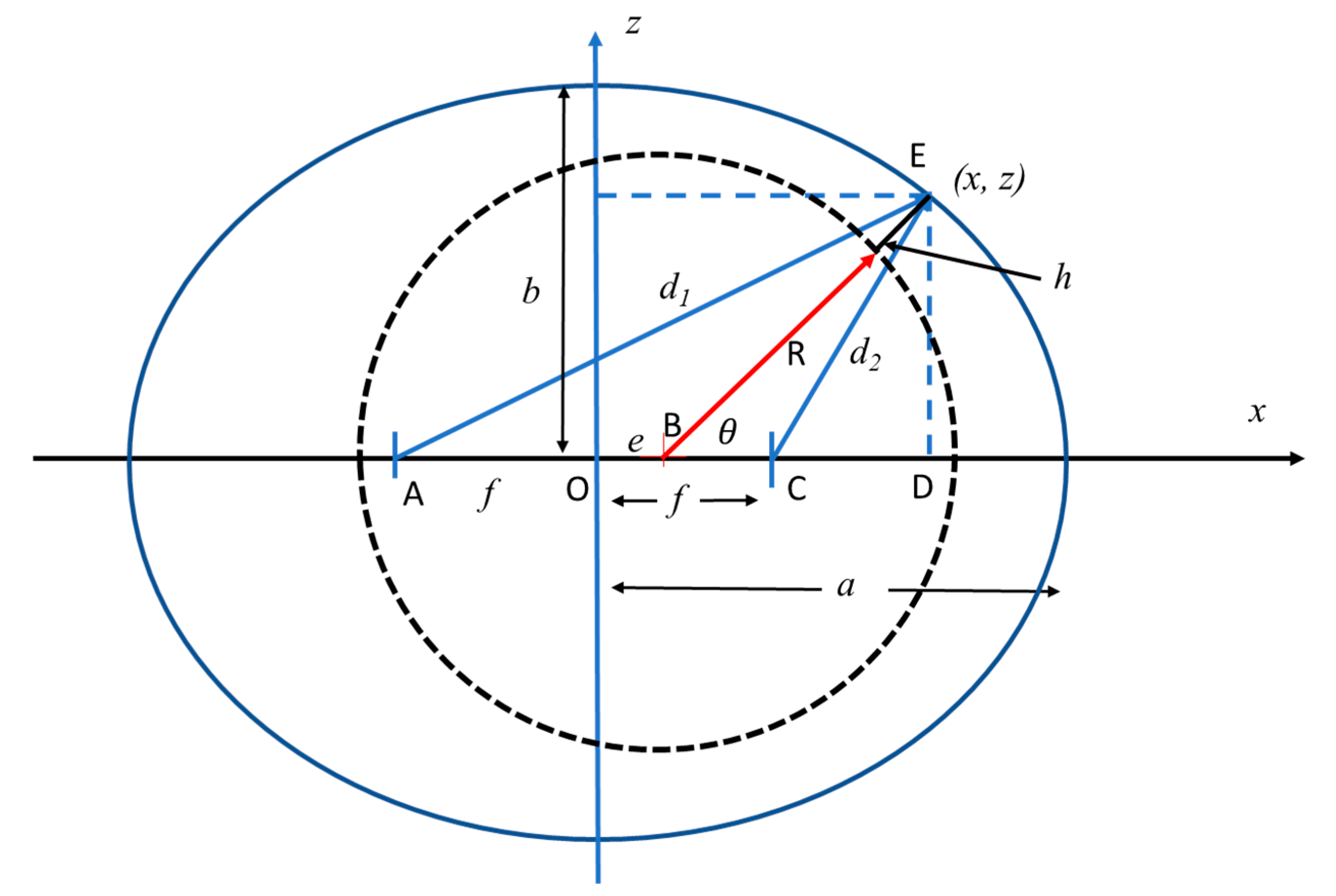
- —which is the film shape pertaining between an eccentric journal and a circular, or elliptical, bearing
- d, the additional clearance created by the flutes, and
- the radial deformation, , of the bearing surface.
3. Results
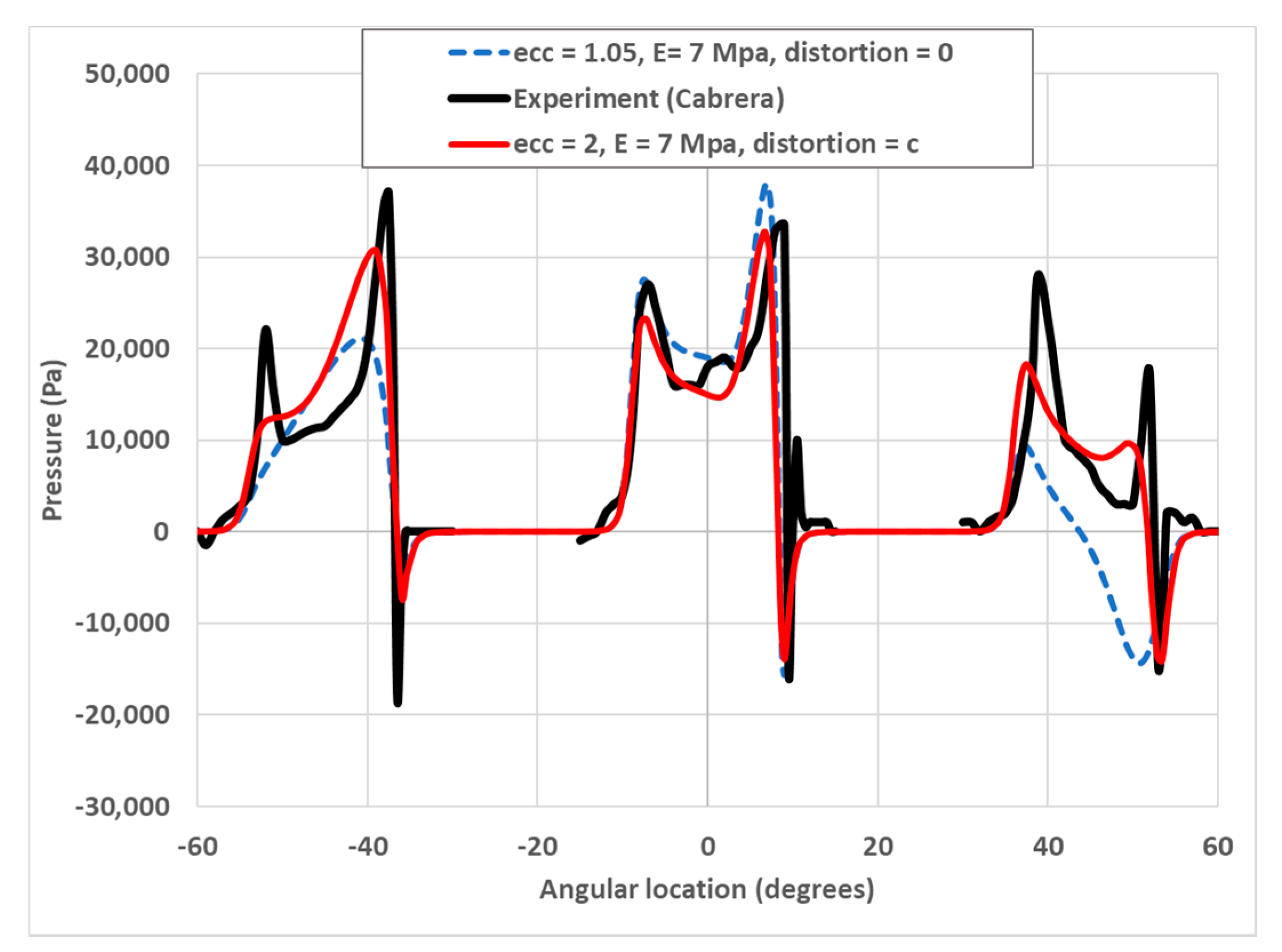
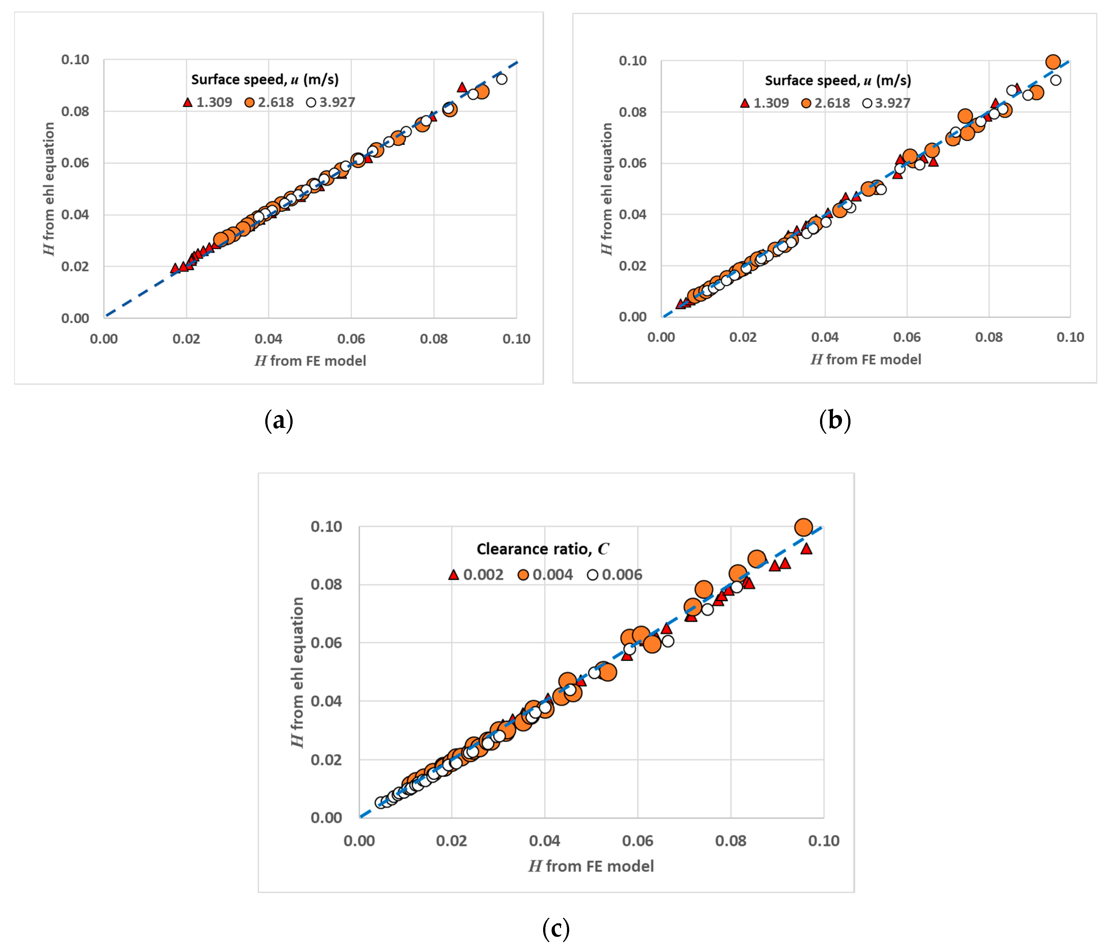
3.1. Validation
3.2. Dimensional Analysis
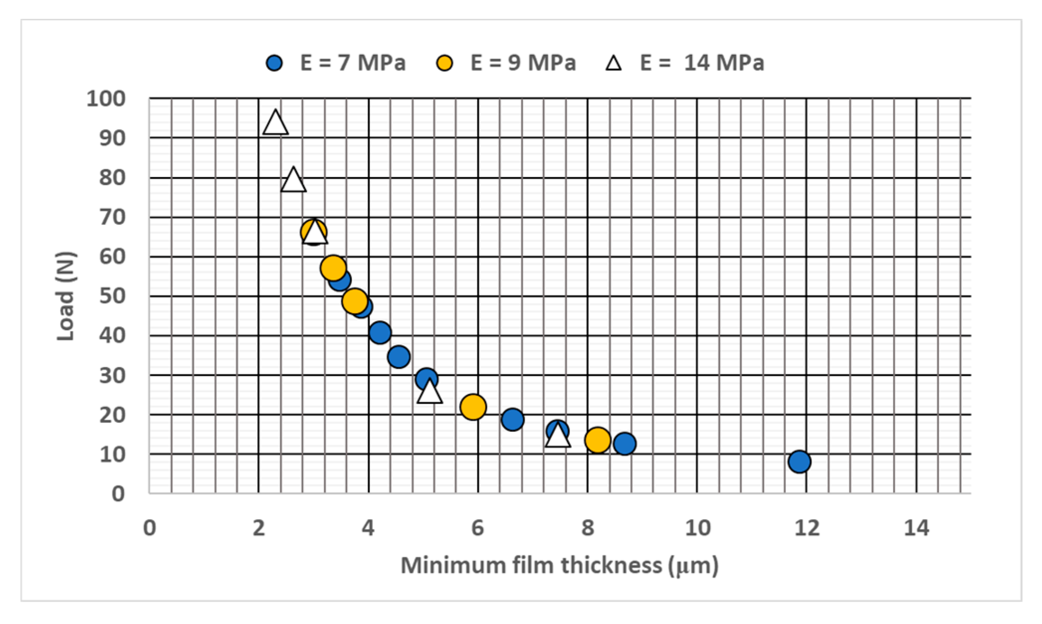
3.3. The Effects of Design Parameters
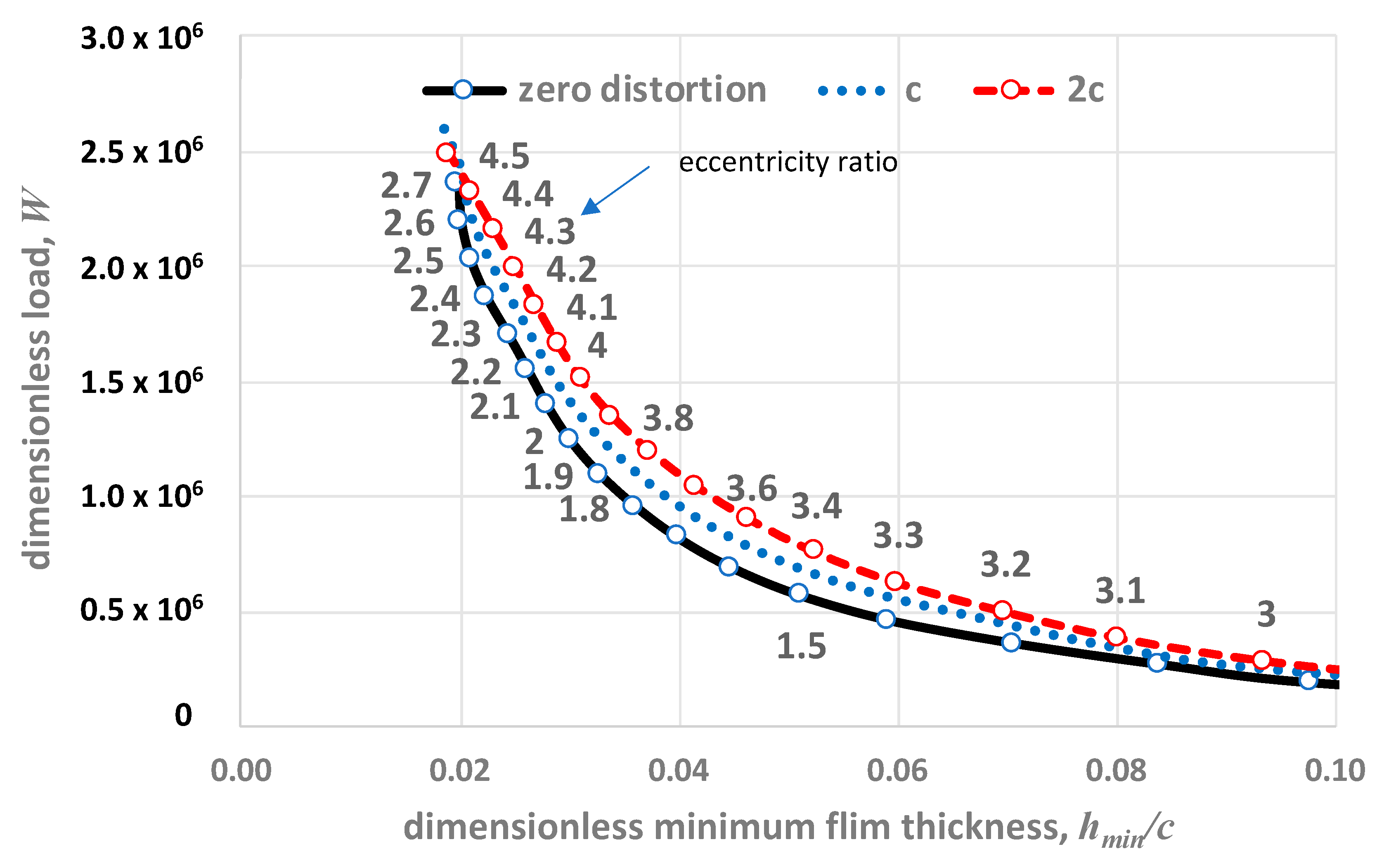
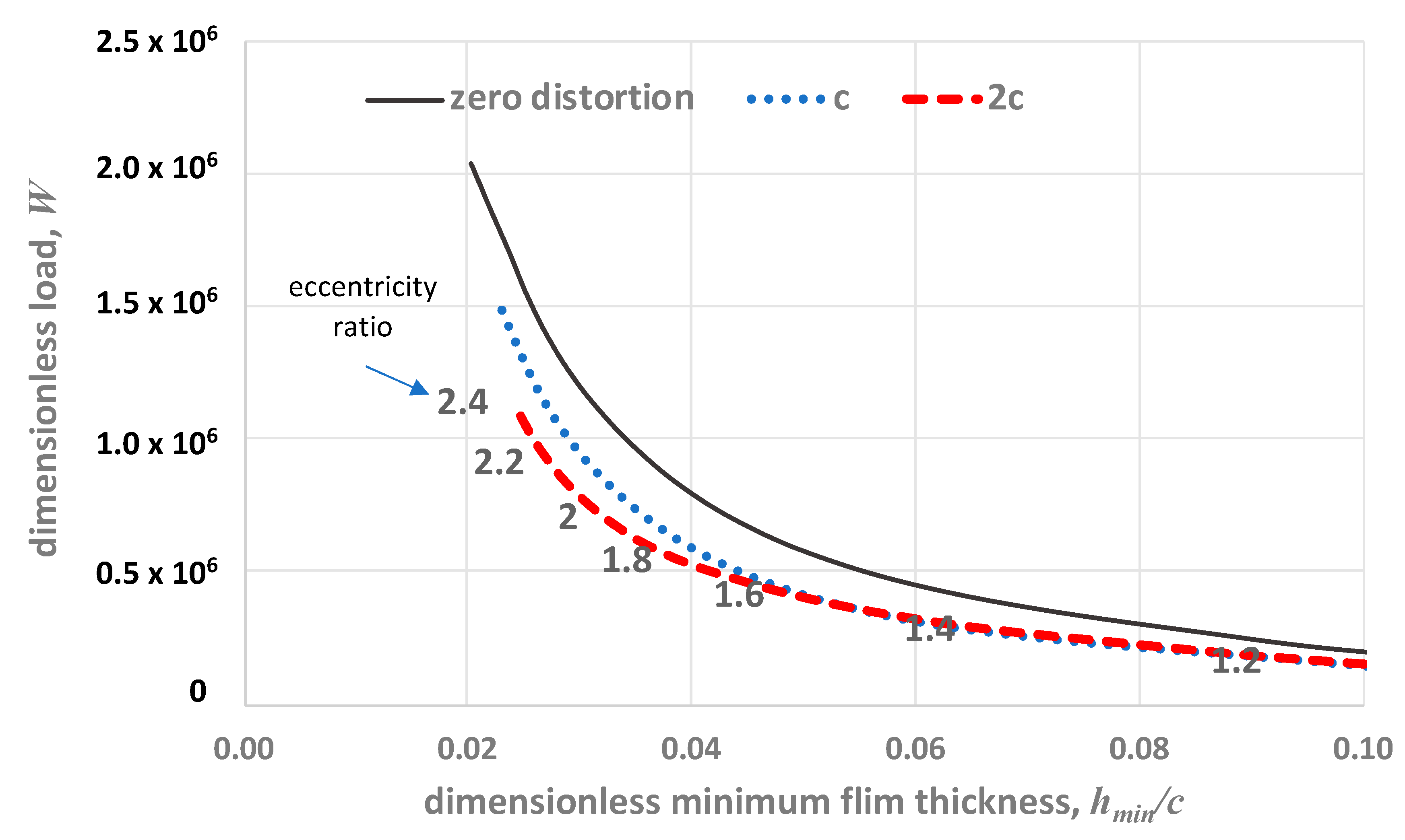
3.3.1. Distortion
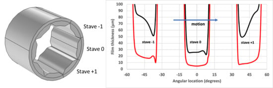
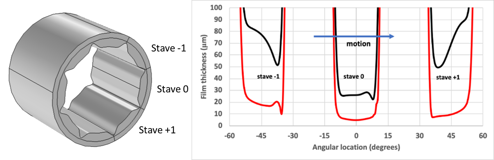
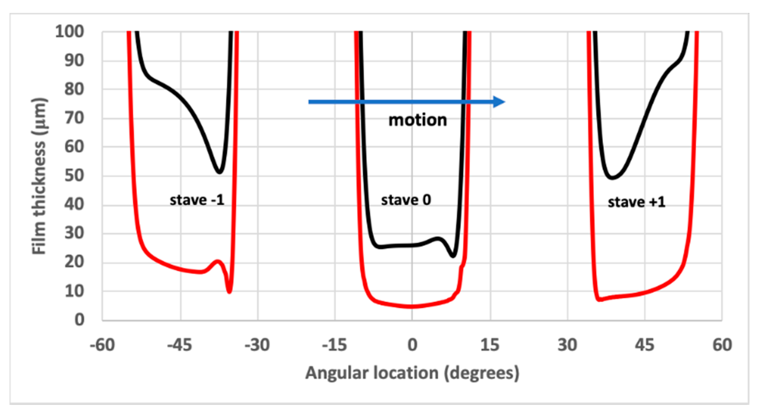
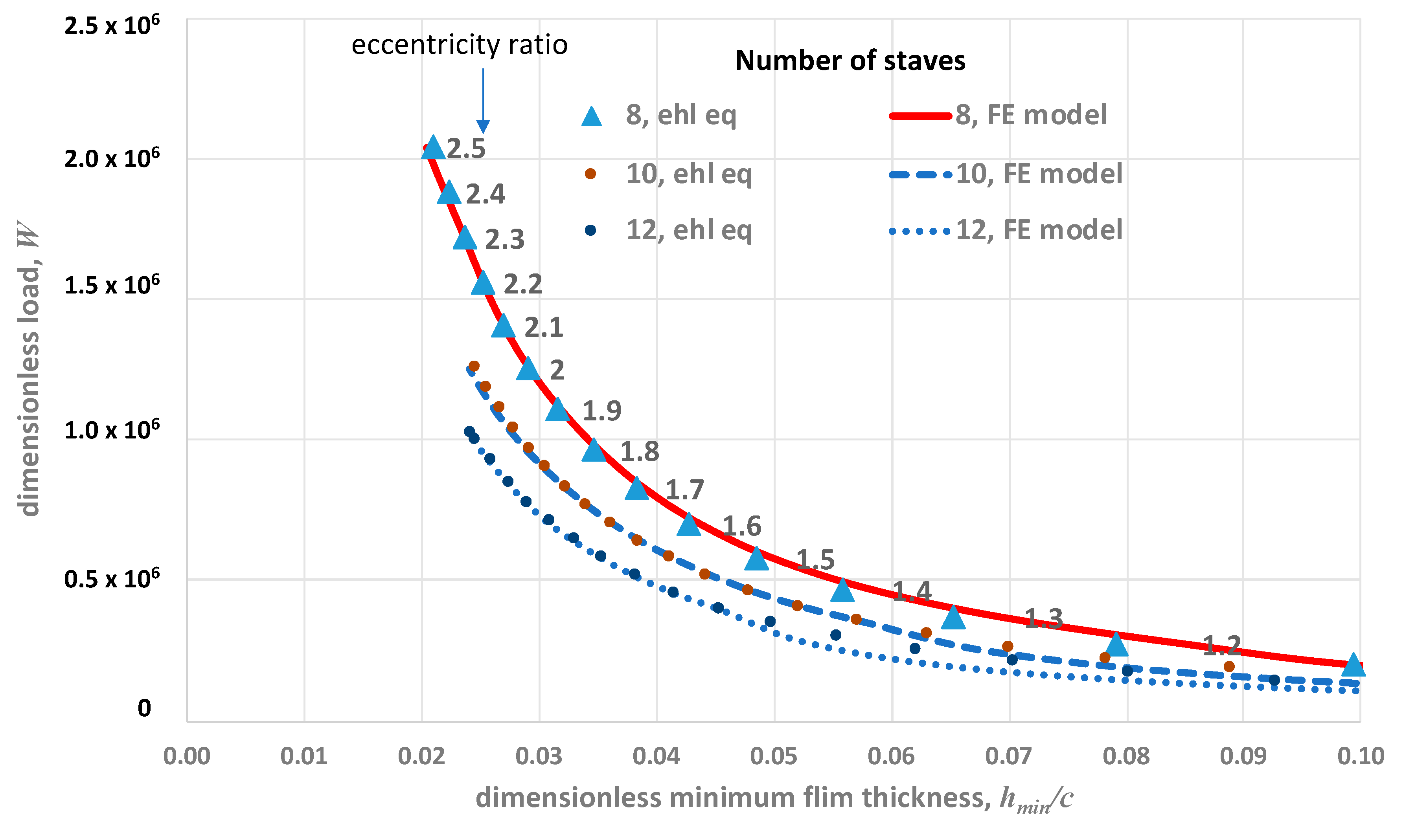
3.3.2. Number of Staves
3.3.3. Clearance Ratio
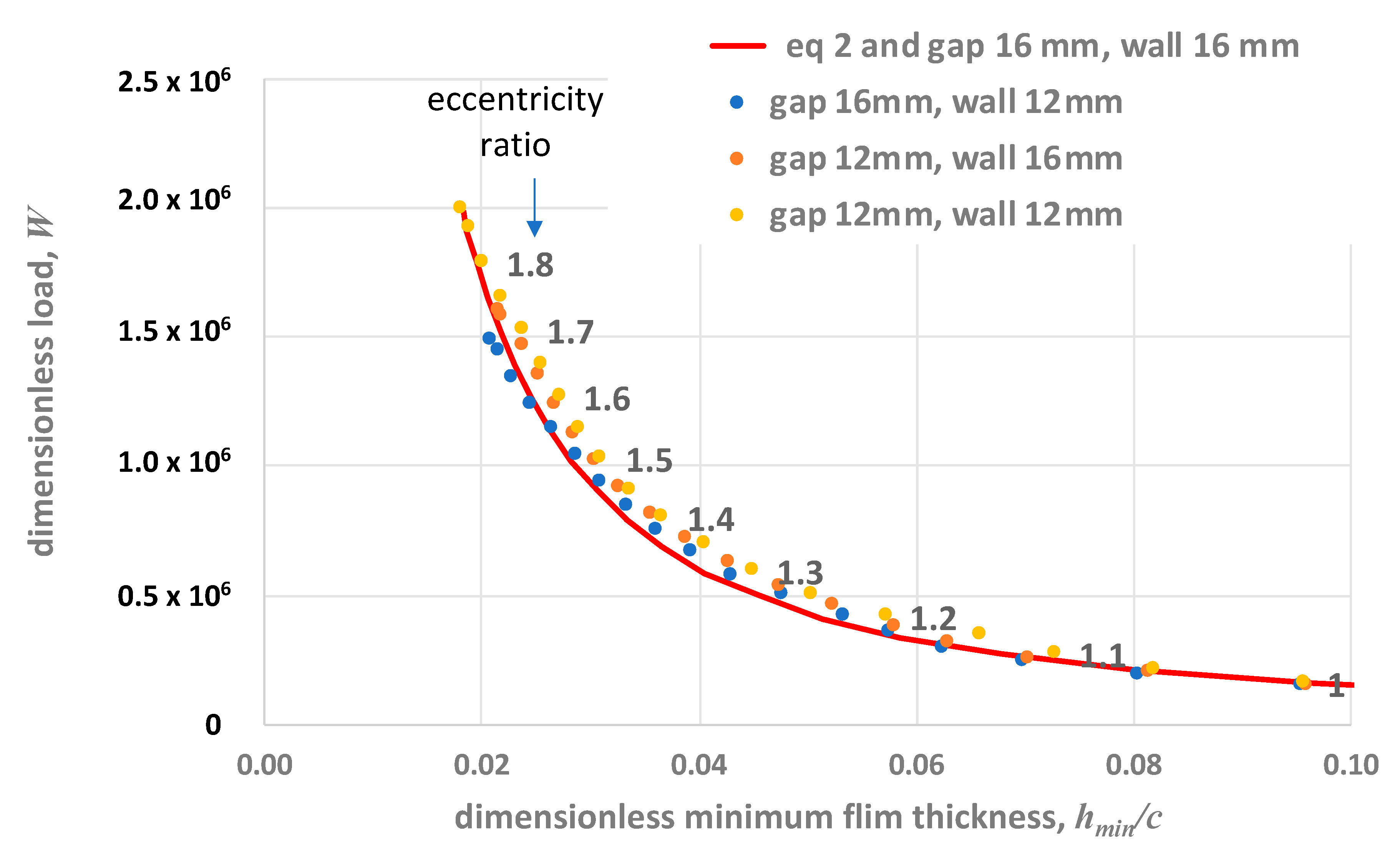
3.3.4. Stave and Flute Geometry
4. Conclusions
Funding
Acknowledgments
Conflicts of Interest
Appendix A

References
- Cabrera, D.L.; Woolley, N.H.; Allanson, D.R.; Tridimas, Y.D. Film pressure distribution in water-lubricated rubber journal bearings. Proc. Inst. Mech. Eng. Part J. J. Eng. Tribol. 2005, 219, 125–132. [Google Scholar] [CrossRef]
- Litwin, W. Experimental research on marine oil-lubricated stern tube bearing. Proc. Inst. Mech. Eng. Part J J. Eng. Tribol. 2019, 233, 1773–1781. [Google Scholar] [CrossRef]
- Zhou, G.; Wang, J.; Han, Y.; Wei, B.; Tang, B.; Zhong, P. An Experimental Study on Film Pressure Circumferential Distribution of Water Lubricated Rubber Bearings with Multiple Grooves. Tribol. Trans. 2017, 60, 385–391. [Google Scholar] [CrossRef]
- Wang, Y.-Q.; Shi, X.-J.; Zhang, L.-J. Experimental and numerical study on water-lubricated rubber bearings. Ind. Lubr. Tribol. 2014, 66, 282–288. [Google Scholar] [CrossRef]
- Ding, X. Numerical simulation of fluid-structure interaction of marine water-lubricated rubber bearings. Ship Build. China 2013, 54, 71–83. [Google Scholar]
- Zhao, H.; Wang, Y.Q. The Elastohydrodynamic Lubrication Analysis of Starved Water-Lubricated Rubber Bearing. Appl. Mech. Mater. 2012, 182, 1529–1532. [Google Scholar] [CrossRef]
- Ding, X.-W.; Wang, J.-X.; Yang, R.-S.; Guo, Y. Analysis of elastic deformation of liner on lubrication performance of water-lubricated structure. Sichuan Daxue Xuebao (Gongcheng Kexue Ban)/J. Sichuan Univ. (Eng. Sci. Ed.) 2012, 44, 233–238. [Google Scholar]
- Wang, Y.Q. Numerical Simulation of Water-Lubricated Rubber/Chromium Coating Pair Test. Adv. Mater. Res. 2012, 502, 351–354. [Google Scholar] [CrossRef]
- Wang, J.; Hua, X.; Xiao, K.; Zhu, J. Two-dimensional study of lubrication mechanism of water-lubricated rubber alloy bearing. Int. J. Comput. Appl. Technol. 2011, 40, 98. [Google Scholar] [CrossRef]
- Wang, Y.; Lin, X. Water lubrication mechanism of the rubber/nickel coating pair. Lubr. Eng. 2006, 1, 54. [Google Scholar]
- Wennehorst, B.; Poll, G. Soft micro-elastohydrodynamic lubrication and friction at rough conformal contacts. Proc. Inst. Mech. Eng. Part J. J. Eng. Tribol. 2016, 231, 302–315. [Google Scholar] [CrossRef]
- Kuang, F.; Zhou, X.; Liu, Z.; Huang, J.; Liu, X.; Qian, K.; Gryllias, K. Computer-vision-based research on friction vibration and coupling of frictional and torsional vibrations in water-lubricated bearing-shaft system. Tribol. Int. 2020, 150, 106336. [Google Scholar] [CrossRef]
- Hongling, Q.; Chang, Y.; Hefa, Z.; Xufei, L.; Zhixiong, L.; Xiang, X. Experimental analysis on friction-induced vibration of water-lubricated bearings in a submarine propulsion system. Ocean Eng. 2020, 203, 107239. [Google Scholar] [CrossRef]
- Wu, C.; Chen, F.; Long, X. The self-excited vibration induced by friction of the shaft-hull coupled system with the water-lubricated rubber bearing and its stick-slip phenomenon. Ocean Eng. 2020, 198, 107002. [Google Scholar] [CrossRef]
- Yang, J.; Liu, Z.; Cheng, Q.; Liu, X.; Deng, T.C. The effect of wear on the frictional vibration suppression of water-lubricated rubber slat with/without surface texture. Wear 2019, 426-427, 1304–1317. [Google Scholar] [CrossRef]
- Kuang, F.; Zhou, X.; Huang, J.; Wang, H.; Zheng, P. Machine-vision-based assessment of frictional vibration in water-lubricated rubber stern bearings. Wear 2019, 426, 1304–1317. [Google Scholar] [CrossRef]
- Qin, W.; Qin, H.; Zheng, H.; Zhang, Z. The coupled effect of bearing misalignment and friction on vibration characteristics of a propulsion shafting system. Proc. Inst. Mech. Eng. Part M. J. Eng. Marit. Environ. 2017, 233, 150–163. [Google Scholar] [CrossRef]
- Yang, J.; Liu, Z.; Liang, X.; Wang, J.; Cheng, Q. Research on Friction Vibration of Marine Water Lubricated Rubber Bearing. Tribol. Online 2018, 13, 108–118. [Google Scholar] [CrossRef]
- Ouyang, W.; Zhang, X.; Jin, Y.; Yuan, X. Experimental Study on the Dynamic Performance of Water-Lubricated Rubber Bearings with Local Contact. Shock Vib. 2018, 2018, 1–10. [Google Scholar] [CrossRef]
- Wang, H.; Liu, Z.; Zou, L.; Yang, J. Influence of both friction and wear on the vibration of marine water lubricated rubber bearing. Wear 2017, 376, 920–930. [Google Scholar] [CrossRef]
- Mallya, R.; Shenoy, S.B.; Pai, R. Steady state characteristics of misaligned multiple axial groove water-lubricated journal bearing. Proc. Inst. Mech. Eng. Part J J. Eng. Tribol. 2014, 229, 712–722. [Google Scholar] [CrossRef]
- Timoshenko, S.P.; Goodier, J.N. Theory of Elasticity; McGraw-Hill: New York, NY, USA, 1982; ISBN 0-07-085805-5. [Google Scholar]


| Parameter | Value | Unit |
|---|---|---|
| Journal radius, R | 25 | mm |
| Radial clearance, c | 0.05, 0.1, 0.15 | mm |
| Bearing length, L | 100 | mm |
| Wall thickness, t | 4 | mm |
| Flute depth, d | 4 | mm |
| Stave width, s | 11 (approx.) | mm |
| Speed | 765 | rpm |
| Viscosity | 0.0008 | Pa.s |
| Density | 1000 | Kg m−3 |
| Young’s moduli | 7, 9, 14 | MPa |
© 2020 by the author. Licensee MDPI, Basel, Switzerland. This article is an open access article distributed under the terms and conditions of the Creative Commons Attribution (CC BY) license (http://creativecommons.org/licenses/by/4.0/).
Share and Cite
Smith, E.H. On the Design and Lubrication of Water-Lubricated, Rubber, Cutlass Bearings Operating in the Soft EHL Regime. Lubricants 2020, 8, 75. https://doi.org/10.3390/lubricants8070075
Smith EH. On the Design and Lubrication of Water-Lubricated, Rubber, Cutlass Bearings Operating in the Soft EHL Regime. Lubricants. 2020; 8(7):75. https://doi.org/10.3390/lubricants8070075
Chicago/Turabian StyleSmith, Edward H. 2020. "On the Design and Lubrication of Water-Lubricated, Rubber, Cutlass Bearings Operating in the Soft EHL Regime" Lubricants 8, no. 7: 75. https://doi.org/10.3390/lubricants8070075
APA StyleSmith, E. H. (2020). On the Design and Lubrication of Water-Lubricated, Rubber, Cutlass Bearings Operating in the Soft EHL Regime. Lubricants, 8(7), 75. https://doi.org/10.3390/lubricants8070075