Mapping the Micro-Abrasion Mechanisms of CoCrMo: Some Thoughts on Varying Ceramic Counterface Diameter on Transition Boundaries In Vitro


Abstract
:
1. Introduction
1.1. Hip Replacement Wear
1.2. Micro-Scale Abrasion
1.3. Importance of Femoral Head Diameter
1.4. Wear Mapping
2. Materials and Methods
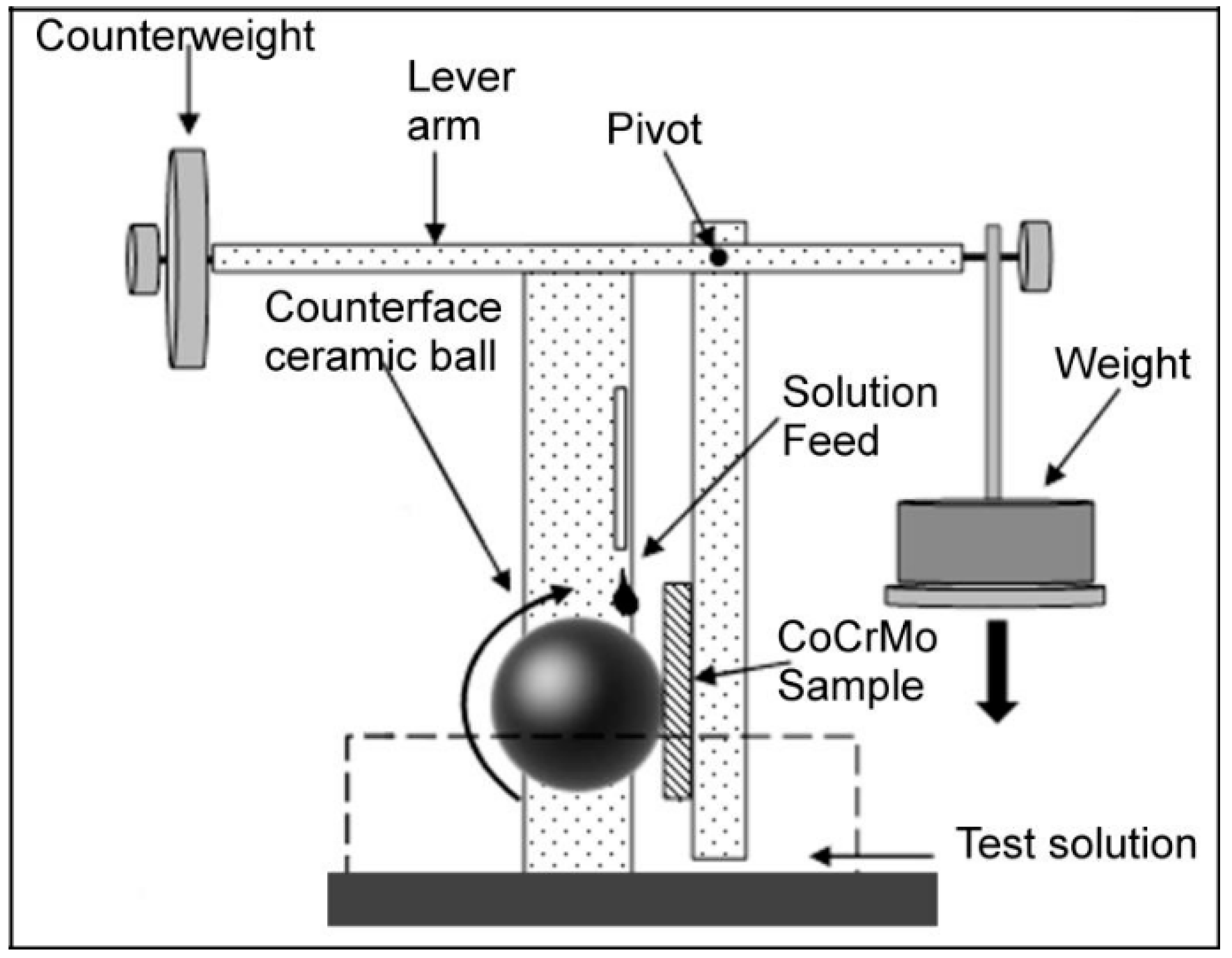
2.1. Experimental Overview
2.2. Test Materials
2.3. Testing Procedure
2.4. Wear Data Analysis
3. Results
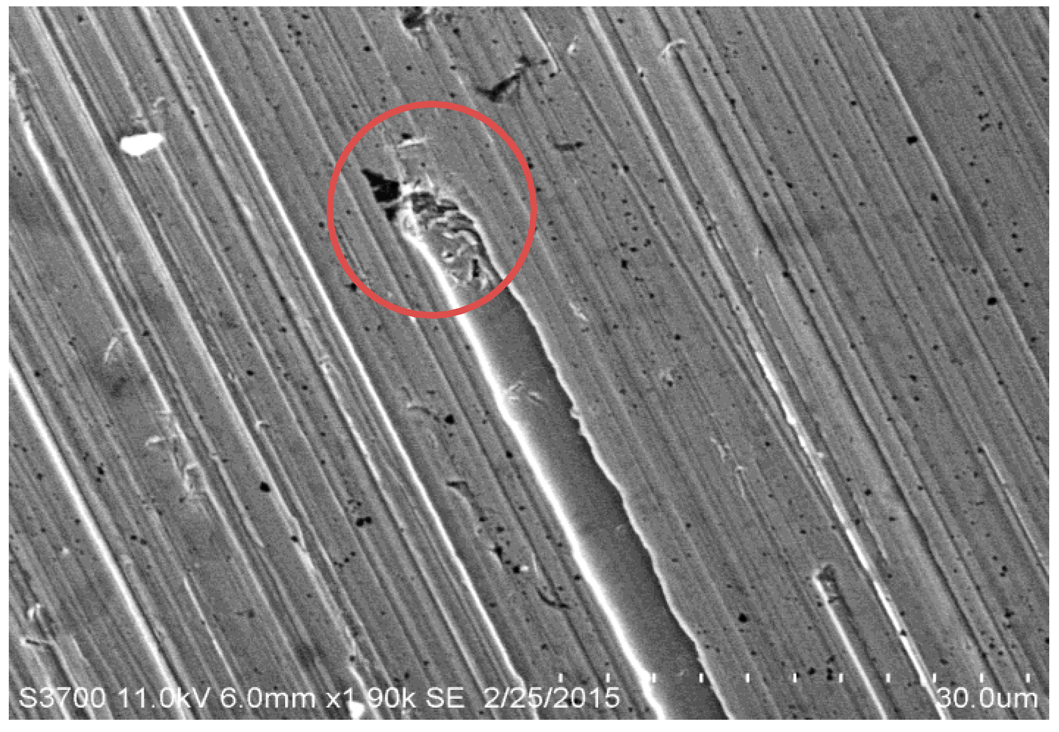
3.1. SEM Analysis of Wear Scars
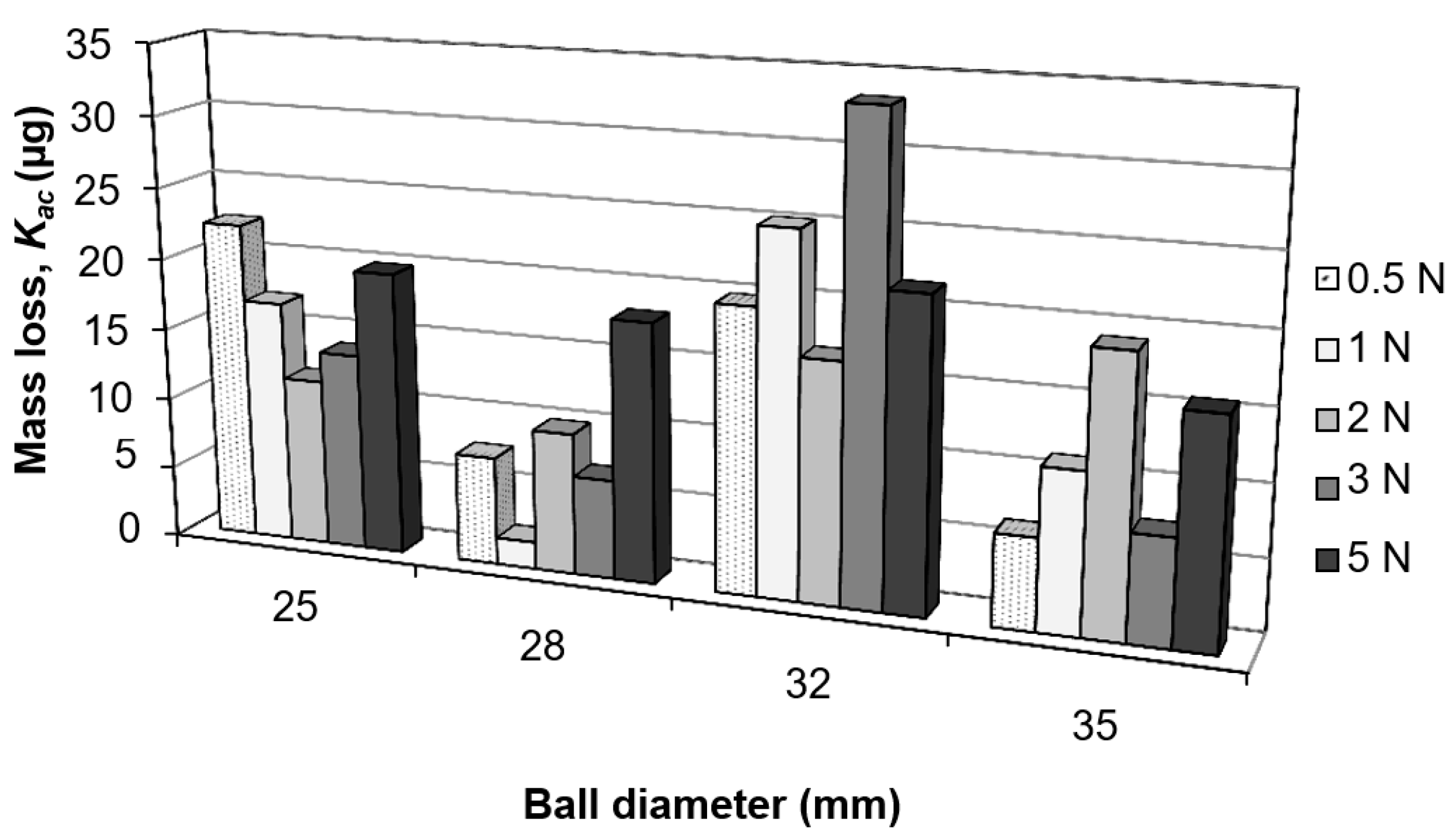
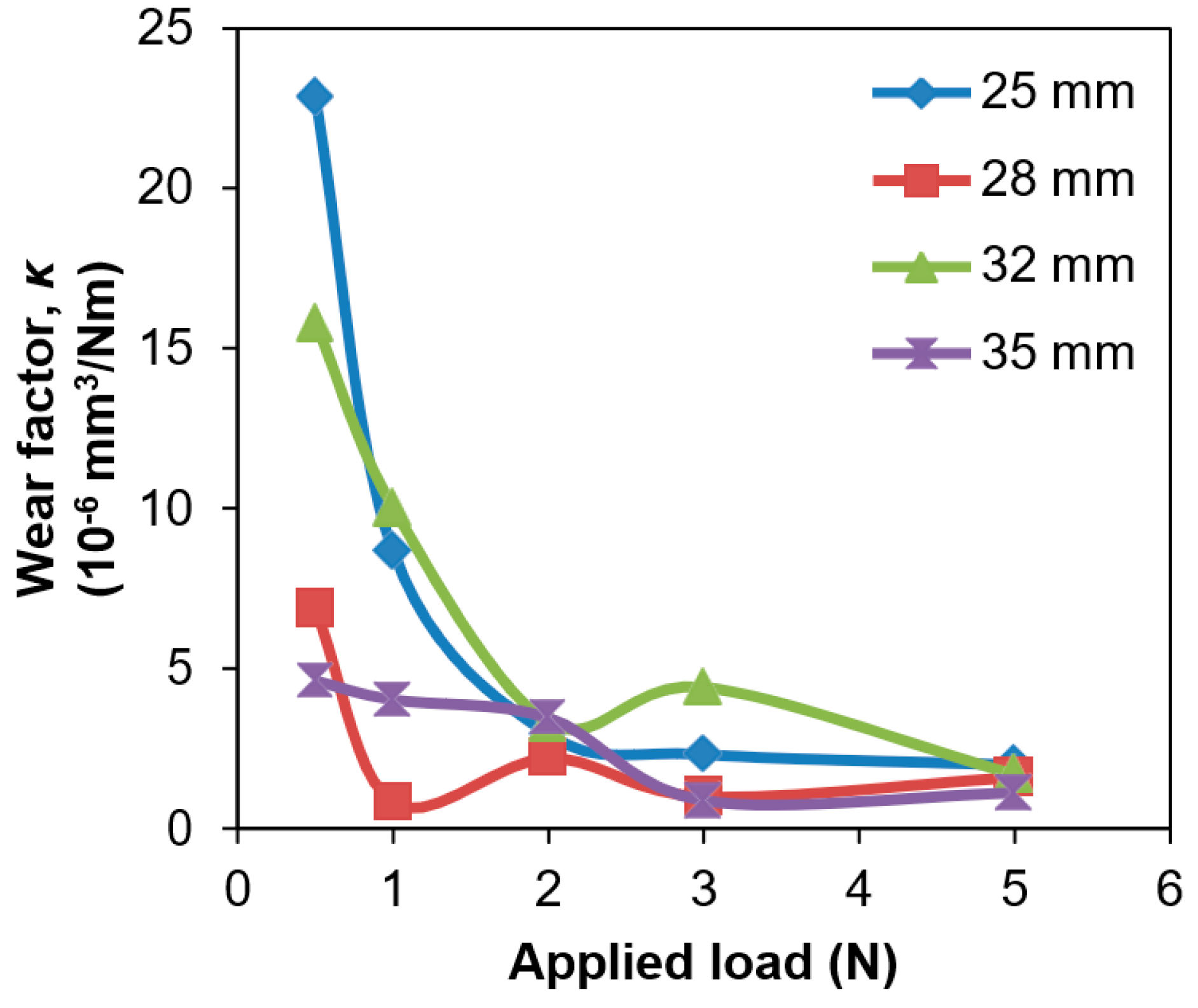
3.2. Wear Volumes
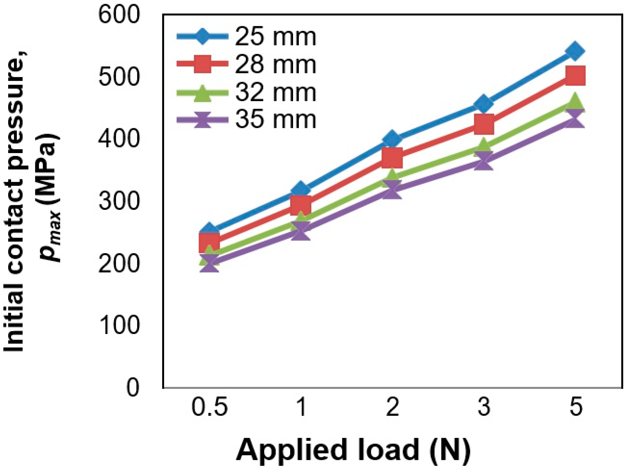
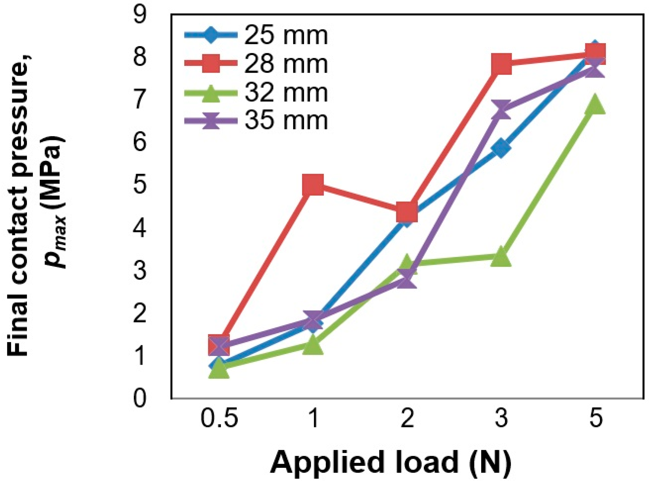
3.3. Contact Pressures
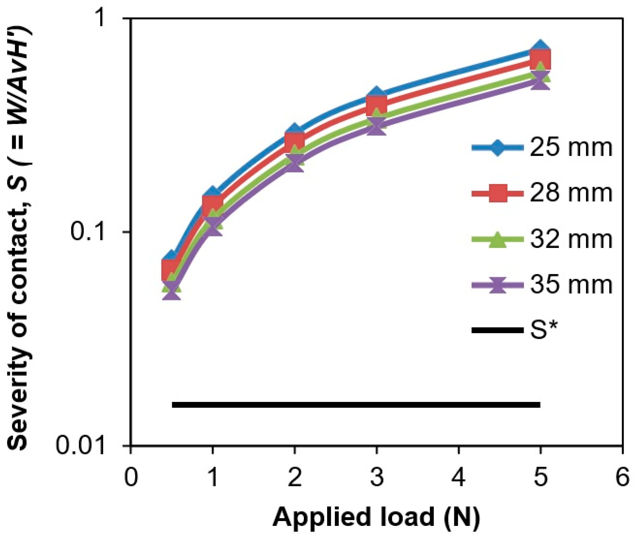
3.4. Severity of Contact, S
4. Discussion
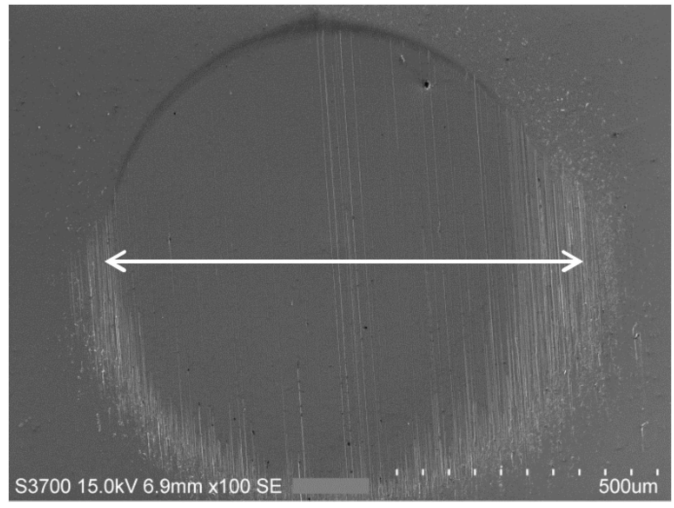
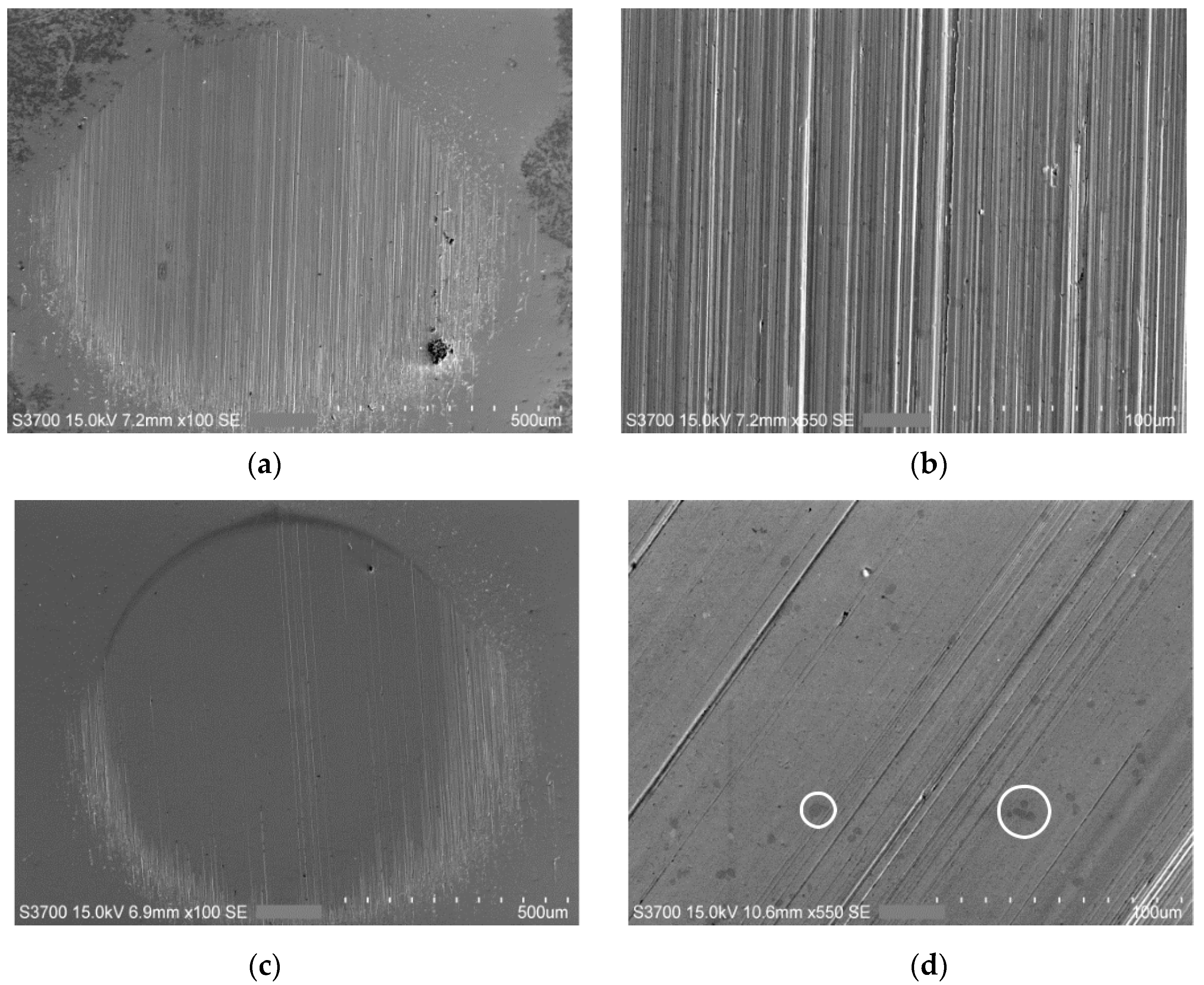
4.1. Wear Scar Topography
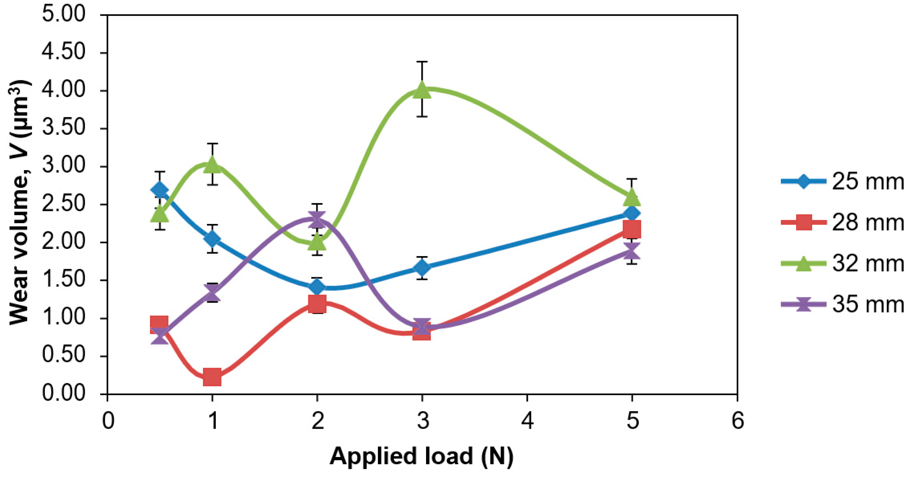
4.2. Wear Volumes
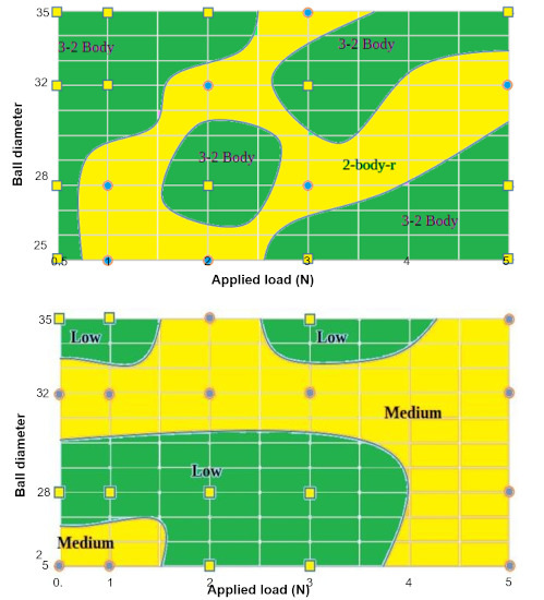
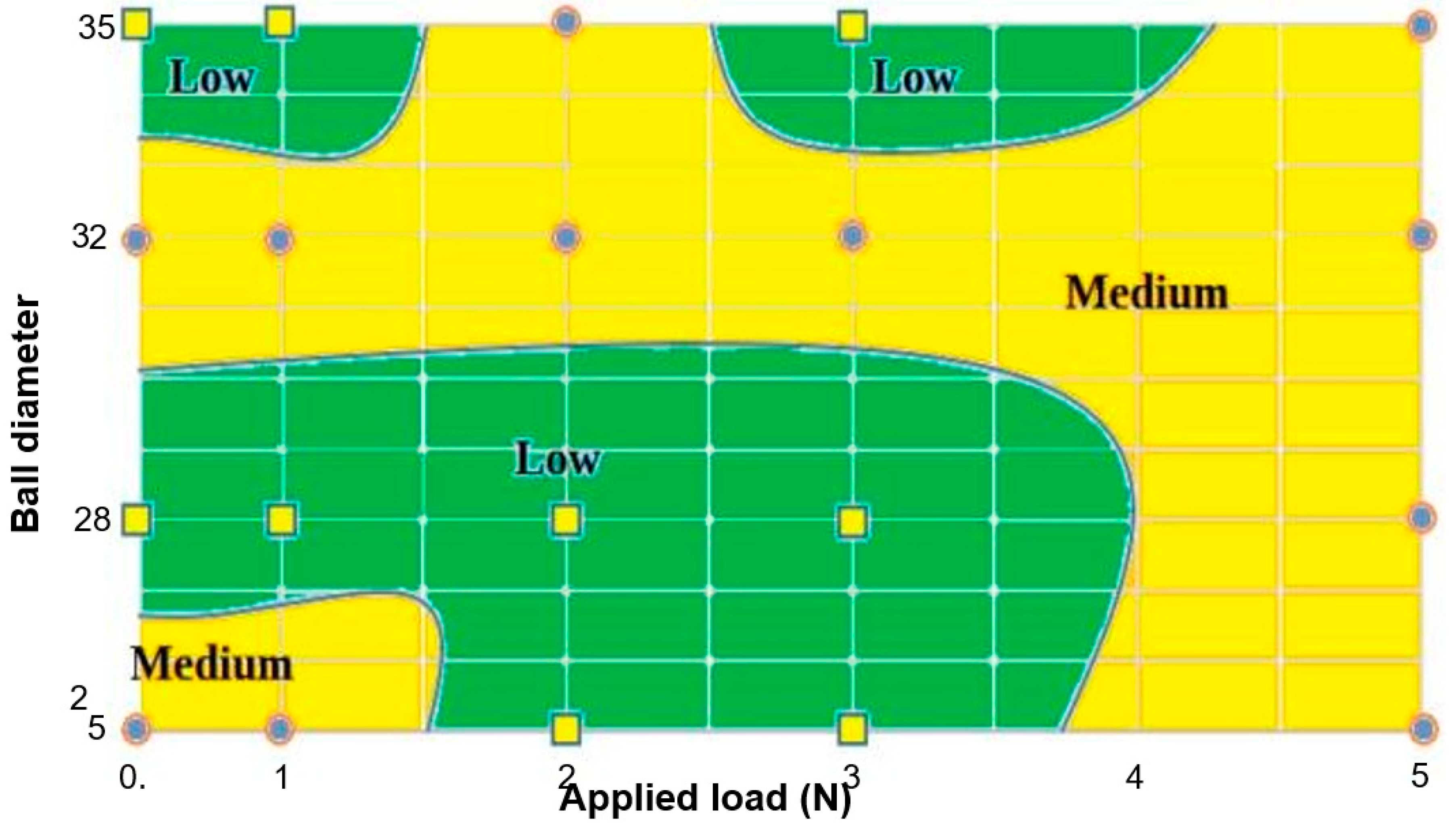
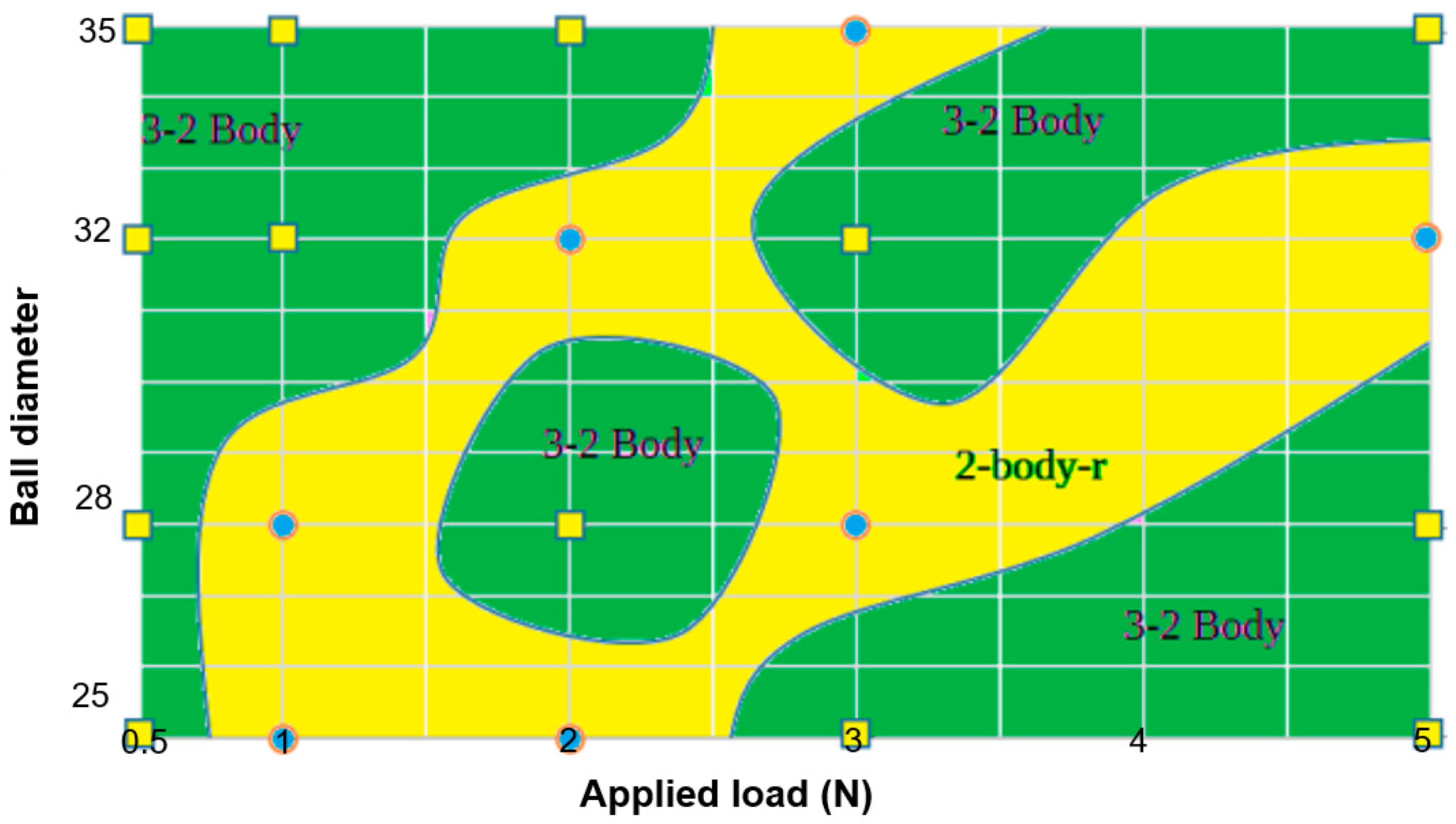
4.3. Wear Mapping
- two- to three-body micro-abrasion: three-body rolling abrasion transitioning into two-body grooving, indicating a linearly increasing wear volume with increasing load.
- two-body ridging (two-body-r) micro-abrasion: for which ‘ridging’ (r) indicates a two-body grooving transition to ridge formation. A decreasing wear volume with increasing load is observed during this regime as a result of particle entrapment within the ridge spaces, or particles being forced out of the wear contact zone towards the outer wear scar.
4.4. Effect of Applied Load and Ball Diameter
4.5. Presence of Protein
5. Conclusions
- (i)
- Contrary to the Archard or Rabinowicz equation, wear volumes may not necessarily occur linearly with an increasing load and sliding distance. Micro-abrasion involves additional factors, indicating a need to develop more accurate models for wear prediction.
- (ii)
- Micro-abrasion wear maps have been constructed as a function of ball diameter and applied load. The micro-abrasion mechanism map indicates significant differences between regions of three-body (mixed) and two-body abrasion regimes for CoCrMo. Similarly, the wastage map indicates significant regions of low and medium mass loss wastage.
- (iii)
- Generally, two- to three-body abrasion dominates. The morphological features of the wear scars often consist of mixed-mode abrasion during light loads, which appears to dominate at larger ball diameters over the applied load range.
- (iv)
- At a 28-mm ball diameter, the lowest wastage is generated with an increasing load. Transitions between two- to three-body and two-body-r abrasion occur most often for the 28-mm and 32-mm ball diameters, depending on the applied load.
- (v)
- The presence of protein may reduce of the severity of contact, Sc, between the abrasive particles and counter-bearing surfaces due to enhanced particle entrainment and increased particle rolling efficiency.
Author Contributions
Funding
Acknowledgments
Conflicts of Interest
References
- Adachi, K.; Hutchings, I. Wear-mode mapping for the micro-scale abrasion test. Wear 2003, 255, 23–29. [Google Scholar] [CrossRef]
- Holzwarth, U.; Cotogno, G. Total Hip Arthroplasty: State of the Art, Challenges and Prospects, JRC Scientific and Policy Reports; Publications Office of the European Union: Brussels, Belgium, 2012. [Google Scholar]
- 12th Annual Report 2015. In National Joint Registry for England, Wales, Northern Island and the Isle of Man; Registry, N.J. (Ed.) NJR: London, UK, 2015. [Google Scholar]
- Malak, T.T.; Beard, D.; Glyn-Jones, S. Total Hip Arthroplasty: Recent Advances and Controversies; Topical Reviews No. 4; Nuffield Orthopaedic Centre: Oxford, UK, 2014; pp. 1–9. [Google Scholar]
- Dowson, D. New joints for the Millennium: Wear control in total replacement hip joints. Proc. Inst. Mech. Eng. Part H J. Eng. Med. 2001, 215, 335–358. [Google Scholar] [CrossRef]
- Gopinathan, P. The Hard on Hard Bearings in THA—Current concepts. J. Orthop. 2014, 11, 113–116. [Google Scholar] [CrossRef] [Green Version]
- Liao, Y.; Hoffman, E.; Wimmer, M.; Fischer, A.; Jacobs, J.J.; Marks, L. CoCrMo metal-on-metal hip replacements. Phys. Chem. Chem. Phys. 2013, 15, 746–756. [Google Scholar] [CrossRef]
- Affatato, S.; Spinelli, M.; Zavalloni, M.; Mazzega-Fabbro, C.; Viceconti, M. Tribology and total hip joint replacement: Current concepts in mechanical simulation. Med. Eng. Phys. 2008, 30, 1305–1317. [Google Scholar] [CrossRef] [PubMed]
- Jin, Z.M.; Stone, M.; Ingham, E.; Fisher, J. (V) Biotribology. Curr. Orthop. 2006, 20, 32–40. [Google Scholar] [CrossRef]
- Pourzal, R.; Urban, R.M.; Wimmer, M.A. What Do the Retrievals Really Tell Us? In Metal-on-Metal Bearings; Springer Science and Business Media LLC: Berlin/Heidelberg, Germany, 2013; pp. 173–193. [Google Scholar]
- Wimmer, M.; Loos, J.; Nassutt, R.; Heitkemper, M.; Fischer, A. The acting wear mechanisms on metal-on-metal hip joint bearings: In vitro results. Wear 2001, 250, 129–139. [Google Scholar] [CrossRef]
- Bhatt, H.; Goswami, T. Implant wear mechanisms—Basic approach. Biomed. Mater. 2008, 3, 42001. [Google Scholar] [CrossRef] [PubMed]
- Affatato, S.; Traina, F.; De Fine, M.; Carmignato, S.; Toni, A. Alumina-on-alumina hip implants: A wear study of retrieved components. J. Bone Jt. Surg. Br. 2012, 94, 37–42. [Google Scholar] [CrossRef] [PubMed]
- Bowsher, J.G.; Clarke, I.C.; Williams, P.; Donaldson, T.K. What is a “Normal” wear pattern for metal-on-metal hip bearings? J. Biomed. Mater. Res. Part B Appl. Biomater. 2009, 91, 297–308. [Google Scholar] [CrossRef]
- Wimmer, M.A.; Sprecher, C.; Hauert, R.; Tager, G.; Fischer, A. Tribochemical reaction on metal-on-metal hip joint bearings—A comparison between in-vitro and in-vivo results. Wear 2003, 255, 1007–1014. [Google Scholar] [CrossRef]
- Mathew, M.T.; Nagelli, C.; Pourzal, R.; Fischer, A.; Laurent, M.; Jacobs, J.J.; Wimmer, M. Tribolayer formation in a metal-on-metal (MoM) hip joint: An electrochemical investigation. J. Mech. Behav. Biomed. Mater. 2013, 29, 199–212. [Google Scholar] [CrossRef] [PubMed] [Green Version]
- Yan, Y.; Neville, A.; Dowson, D.; Williams, S.; Fisher, J. Tribofilm formation in biotribocorrosion—Does it regulate ion release in metal-on-metal artificial hip joints? Proc. Inst. Mech. Eng. Part J J. Eng. Tribol. 2010, 224, 997–1006. [Google Scholar] [CrossRef]
- Wang, A.; Essner, A. Three-body wear of UHMWPE acetabular cups by PMMA particles against CoCr, alumina and zirconia heads in a hip joint simulator. Wear 2001, 250, 212–216. [Google Scholar] [CrossRef]
- Firkins, P.; Tipper, J.; Ingham, E.; Stone, M.; Farrar, R.; Fisher, J. A novel low wearing differential hardness, ceramic-on-metal hip joint prosthesis. J. Biomech. 2001, 34, 1291–1298. [Google Scholar] [CrossRef]
- Barnes, C.L.; DeBoer, D.; Corpe, R.S.; Nambu, S.; Carroll, M.; Timmerman, I. Wear Performance of Large-Diameter Differential-Hardness Hip Bearings. J. Arthroplast. 2008, 23, 56–60. [Google Scholar] [CrossRef]
- Huet, R.; Sakona, A.; Kurtz, S.M. Strength and reliability of alumina ceramic femoral heads: Review of design, testing, and retrieval analysis. J. Mech. Behav. Biomed. Mater. 2011, 4, 476–483. [Google Scholar] [CrossRef]
- Jeffers, J.R. The role of biomechanics and engineering in total hip replacement. Why surgeons need technical help. Proc. Inst. Mech. Eng. Part H J. Eng. Med. 2012, 226, 947–954. [Google Scholar] [CrossRef] [PubMed]
- Gant, A.J.; Gee, M. A review of micro-scale abrasion testing. J. Phys. D Appl. Phys. 2011, 44, 73001. [Google Scholar] [CrossRef]
- Sinnett-Jones, P.; Wharton, J.; Wood, R.J. Micro-abrasion–corrosion of a CoCrMo alloy in simulated artificial hip joint environments. Wear 2005, 259, 898–909. [Google Scholar] [CrossRef]
- Stack, M.M.; Jawan, H.; Mathew, M.T. On the construction of micro-abrasion maps for a steel/polymer couple in corrosive environments. Tribol. Int. 2005, 38, 848–856. [Google Scholar] [CrossRef]
- Sadiq, K.; Black, R.A.; Stack, M.M. Bio-tribocorrosion mechanisms in orthopaedic devices: Mapping the micro-abrasion–corrosion behaviour of a simulated CoCrMo hip replacement in calf serum solution. Wear 2014, 316, 58–69. [Google Scholar] [CrossRef] [Green Version]
- Williams, J.A. Wear and wear particles—Some fundamentals. Tribol. Int. 2005, 38, 863–870. [Google Scholar] [CrossRef]
- Allsopp, D.; Trezona, R.; Hutchings, I. The effects of ball surface condition in the micro-scale abrasive wear test. Tribol. Lett. 1998, 5, 259–264. [Google Scholar] [CrossRef]
- Cooper, H.J.; Della Valle, C.J. Large diameter femoral heads. Bone Jt. J. 2014, 96, 23–26. [Google Scholar] [CrossRef] [PubMed]
- Lim, S.C. Wear Maps. In Encyclopedia of Tribology; Springer Science and Business Media LLC: Berlin/Heidelberg, Germany, 2013; pp. 4007–4012. [Google Scholar]
- Hsu, S.; Shen, M.; Ruff, A. Wear prediction for metals. Tribol. Int. 1997, 30, 377–383. [Google Scholar] [CrossRef]
- Stack, M.M. Bridging the gap between tribology and corrosion: From wear maps to Pourbaix diagrams. Int. Mater. Rev. 2005, 50, 1–17. [Google Scholar] [CrossRef]
- Lim, S.; Ashby, M. Overview no. 55 Wear-Mechanism maps. Acta Met. 1987, 35, 1–24. [Google Scholar] [CrossRef]
- Stack, M.M.; Rodling, J.; Mathew, M.T.; Jawan, H.; Huang, W.; Park, G.; Hodge, C. Micro-abrasion–corrosion of a Co–Cr/UHMWPE couple in Ringer’s solution: An approach to construction of mechanism and synergism maps for application to bio-implants. Wear 2010, 269, 376–382. [Google Scholar] [CrossRef] [Green Version]
- Sadiq, K.; Stack, M.M.; Black, R.A. Wear mapping of CoCrMo alloy in simulated bio-tribocorrosion conditions of a hip prosthesis bearing in calf serum solution. Mater. Sci. Eng. C 2015, 49, 452–462. [Google Scholar] [CrossRef] [Green Version]
- Amini, S.; Miserez, A. Wear and abrasion resistance selection maps of biological materials. Acta Biomater. 2013, 9, 7895–7907. [Google Scholar] [CrossRef]
- Petersen, D.R.; Link, R.E.; Rutherford, K.L.; Hutchings, I.M. Theory and Application of a Micro-Scale Abrasive Wear Test. J. Test. Eval. 1997, 25, 250. [Google Scholar] [CrossRef]
- Roylance, B.J.; Williams, J.A.; Dwyer-Joyce, R. Wear debris and associated wear phenomena—Fundamental research and practice. Proc. Inst. Mech. Eng. Part J J. Eng. Tribol. 2000, 214, 79–105. [Google Scholar] [CrossRef]
- Liao, Y.; Pourzal, R.; Wimmer, M.A.; Jacobs, J.J.; Fischer, A.; Marks, L.D. Graphitic Tribological Layers in Metal-on-Metal Hip Replacements. Science 2011, 334, 1687–1690. [Google Scholar] [CrossRef] [PubMed] [Green Version]
- Greer, A.L.; Rutherford, K.L.; Hutchings, I.M. Wear resistance of amorphous alloys and related materials. Int. Mater. Rev. 2002, 47, 87–112. [Google Scholar] [CrossRef]
- Hamilton, G.M. Explicit Equations for the Stresses beneath a Sliding Spherical Contact. Proc. Inst. Mech. Eng. Part C J. Mech. Eng. Sci. 1983, 197, 53–59. [Google Scholar] [CrossRef]
- Sharma, R.; Vannabouathong, C.; Bains, S.; Marshall, A.; Macdonald, S.J.; Parvizi, J.; Bhandari, M. Meta-Analyses in Joint Arthroplasty: A Review of Quantity, Quality, and Impact. J. Bone Jt. Surg. Am. Vol. 2011, 93, 2304–2309. [Google Scholar] [CrossRef]
- Adachi, K.; Hutchings, I. Sensitivity of wear rates in the micro-scale abrasion test to test conditions and material hardness. Wear 2005, 258, 318–321. [Google Scholar] [CrossRef]
- Trezona, R.; Allsopp, D.; Hutchings, I. Transitions between two-body and three-body abrasive wear: Influence of test conditions in the microscale abrasive wear test. Wear 1999, 225, 205–214. [Google Scholar] [CrossRef]
- Stack, M.M.; Mathew, M.T. Micro-abrasion transitions of metallic materials. Wear 2003, 255, 14–22. [Google Scholar] [CrossRef]
- Williams, J.; Hyncica, A. Mechanisms of abrasive wear in lubricated contacts. Wear 1992, 152, 57–74. [Google Scholar] [CrossRef]
- Stack, M.M.; Chi, K. Mapping sliding wear of steels in aqueous conditions. Wear 2003, 255, 456–465. [Google Scholar] [CrossRef]
- Sun, D.; Wharton, J.; Wood, R. Micro-abrasion mechanisms of cast CoCrMo in simulated body fluids. Wear 2009, 267, 1845–1855. [Google Scholar] [CrossRef]
- Wimmer, M.A.; Fischer, A.; Büscher, R.; Pourzal, R.; Sprecher, C.; Hauert, R.; Jacobs, J.J. Wear mechanisms in metal-on-metal bearings: The importance of tribochemical reaction layers. J. Orthop. Res. 2009, 28, 436–443. [Google Scholar] [CrossRef]
- Yan, Y.; Wang, L.; Neville, A.; Qiao, L. (IV) Tribofilm on hip implants. Orthop. Trauma 2013, 27, 93–100. [Google Scholar] [CrossRef]
- Yan, Y.; Neville, A.; Dowson, D. Biotribocorrosion of CoCrMo orthopaedic implant materials—Assessing the formation and effect of the biofilm. Tribol. Int. 2007, 40, 1492–1499. [Google Scholar] [CrossRef]
- Yan, Y.; Neville, A.; Dowson, D.; Williams, S.; Fisher, J. Tribo-corrosion analysis of wear and metal ion release interactions from metal-on-metal and ceramic-on-metal contacts for the application in artificial hip prostheses. Proc. Inst. Mech. Eng. Part J J. Eng. Tribol. 2008, 222, 483–492. [Google Scholar] [CrossRef]
- Sun, D.; Wharton, J.A.; Wood, R.J.K. The Effects of Protein and pH on the Tribo-Corrosion Performance of Cast CoCrMo—A Combined Electrochemical and Tribological Study. Adv. Tribol. 2009, 825–826. [Google Scholar] [CrossRef]


| Element | Chemical Composition (wt. %) |
|---|---|
| Co | Bal. |
| Cr | 27.56 |
| Mo | 5.70 |
| Mn | 0.60 |
| Si | 0.38 |
| C | 0.03 |
| Al | <0.02 |
| Material | Density (kg/m3) | Hardness (GPa) | Young’s Modulus (GPa) | Poisson’s Ratio | |
|---|---|---|---|---|---|
| Specimen | CoCrMo | 8300 | 3.83 | 248 | 0.30 |
| Ball | Al2O3 | 3950 | 16.67 | 370 | 0.22 |
| Abrasive particles | SiC | 3200 | 27.46 | 410 | 0.14 |
| Applied Loads (N) | 0.5, 1, 2, 3, 5 |
| Abrasive Particles | SiC particles (mean particle size 3 µm, standard deviation ± 0.5 µm) |
| Slurry Concentration (v/v) | 0.0078 |
| Pump Feed Rate (mL h−1) | Up to 60 |
| Speed of Rotation (rpm) | 100 |
| Ball Diameters (mm) | 25, 28, 32, 35 |
| Testing Duration (s) | 1800 |
| Ball Diameter (mm) | Applied Load (N) | Mass Loss, Κac (µg) | Wear Volume, V (mm3) | Wear Factor, κ (×10−6 mm3/Nm) | Wear Rate (mm3/106 cycles) | Severity of Contact, Sc | S/S* |
|---|---|---|---|---|---|---|---|
| 25 | 0.5 | 22.35 | 0.003 | 22.87 | 0.90 | 0.07 | 4.74 |
| 1 | 17.01 | 0.002 | 8.70 | 0.68 | 0.15 | 9.41 | |
| 2 | 11.70 | 0.001 | 2.99 | 0.47 | 0.29 | 18.64 | |
| 3 | 13.82 | 0.002 | 2.36 | 0.56 | 0.43 | 27.73 | |
| 5 | 19.81 | 0.002 | 2.03 | 0.80 | 0.71 | 45.57 | |
| 28 | 0.5 | 7.56 | 0.001 | 6.91 | 0.30 | 0.07 | 4.23 |
| 1 | 1.88 | 0.000 | 0.86 | 0.08 | 0.13 | 8.41 | |
| 2 | 9.86 | 0.001 | 2.25 | 0.40 | 0.26 | 16.66 | |
| 3 | 6.91 | 0.001 | 1.05 | 0.28 | 0.39 | 24.79 | |
| 5 | 18.10 | 0.002 | 1.65 | 0.73 | 0.64 | 40.76 | |
| 32 | 0.5 | 19.80 | 0.002 | 15.82 | 0.80 | 0.06 | 3.70 |
| 1 | 25.16 | 0.003 | 10.06 | 1.01 | 0.12 | 7.36 | |
| 2 | 16.71 | 0.002 | 3.34 | 0.67 | 0.23 | 14.59 | |
| 3 | 33.38 | 0.004 | 4.45 | 1.34 | 0.34 | 21.72 | |
| 5 | 21.63 | 0.003 | 1.73 | 0.87 | 0.56 | 35.74 | |
| 35 | 0.5 | 6.36 | 0.001 | 4.65 | 0.26 | 0.05 | 3.39 |
| 1 | 11.10 | 0.001 | 4.06 | 0.45 | 0.11 | 6.73 | |
| 2 | 19.12 | 0.002 | 3.49 | 0.77 | 0.21 | 13.35 | |
| 3 | 7.41 | 0.001 | 0.90 | 0.30 | 0.31 | 19.88 | |
| 5 | 15.69 | 0.002 | 1.15 | 0.63 | 0.51 | 32.72 |
© 2020 by the authors. Licensee MDPI, Basel, Switzerland. This article is an open access article distributed under the terms and conditions of the Creative Commons Attribution (CC BY) license (http://creativecommons.org/licenses/by/4.0/).
Share and Cite
Sadiq, K.; Sim, M.A.; Black, R.A.; Stack, M.M. Mapping the Micro-Abrasion Mechanisms of CoCrMo: Some Thoughts on Varying Ceramic Counterface Diameter on Transition Boundaries In Vitro. Lubricants 2020, 8, 71. https://doi.org/10.3390/lubricants8070071
Sadiq K, Sim MA, Black RA, Stack MM. Mapping the Micro-Abrasion Mechanisms of CoCrMo: Some Thoughts on Varying Ceramic Counterface Diameter on Transition Boundaries In Vitro. Lubricants. 2020; 8(7):71. https://doi.org/10.3390/lubricants8070071
Chicago/Turabian StyleSadiq, Kamran, Mark A. Sim, Richard A. Black, and Margaret M. Stack. 2020. "Mapping the Micro-Abrasion Mechanisms of CoCrMo: Some Thoughts on Varying Ceramic Counterface Diameter on Transition Boundaries In Vitro" Lubricants 8, no. 7: 71. https://doi.org/10.3390/lubricants8070071
APA StyleSadiq, K., Sim, M. A., Black, R. A., & Stack, M. M. (2020). Mapping the Micro-Abrasion Mechanisms of CoCrMo: Some Thoughts on Varying Ceramic Counterface Diameter on Transition Boundaries In Vitro. Lubricants, 8(7), 71. https://doi.org/10.3390/lubricants8070071