Article

On Waviness and Two-Sided Surface Features in Thermal Elastohydrodynamically Lubricated Line Contacts

Division of Machine Elements, Luleå University of Technology, 97187 Luleå, Sweden
*
Author to whom correspondence should be addressed.
Lubricants 2020, 8(6), 64; https://doi.org/10.3390/lubricants8060064
Submission received: 20 May 2020 / Revised: 8 June 2020 / Accepted: 10 June 2020 / Published: 13 June 2020

Abstract

:
Machine components are designed to endure increasingly severe operating conditions due to the strive for improved energy efficiency of mechanical systems. Consequently, lubricated non-conformal contacts must rely on thin lubricant films where the influence of surface topography on the lubricating conditions becomes significant. Due to the complexity of the multiphysical problem, approximate assumptions are often employed to facilitate numerical studies of elastohydrodynamically lubricated (EHL) contacts. In this work, the rough, time dependent, thermal EHL problem is solved with focus on two main analyses. The first analysis focuses on the influence of sinusoidal roughness and the difference between a thermal non-Newtonian approach and an isothermal Newtonian approach. The second analysis is focused on the lubricating mechanisms taking place when two-sided surface features overtake within the thermal EHL contact. The results indicate that the film thickness in the outlet of the contact may be significantly overestimated by an isothermal Newtonian approach and that differences in the high-pressure region may also occur due to viscosity variations in the inlet of the contact. Moreover, for the studied two-sided surface features, it became evident that not only the surface feature combination but also the overtaking position influence the film thickness and pressure variations significantly.

1. Introduction

The current strive to improve energy efficiency of mechanical systems has led to machine components being designed to endure increasingly severe operating conditions. This generally implies an increased power density and reduced lubricant viscosity, which further results in reduced lubricant film thicknesses separating the contacting surfaces in highly loaded non-conformal contacts, typically found in for example, bearings, gears and cam-roller follower mechanisms. Thereby, a deeper understanding of how surface topography influences the lubricating performance becomes essential for improving the design of machine components and to achieve desired durability. Consequently, the general understanding of how surface roughness influences the lubricating performance of elastohydrodynamically lubricated (EHL) contacts has been significantly improved over the past years, see for example, Morales-Espejel [1].
Many important contributions to the understanding of non-smooth EHL contacts include those of a numerical nature, which were enabled with reasonable convergence rates and sufficient accuracy after the multi-grid technique was applied to the EHL problem by Lubrecht et al. [2,3] and Lubrecht [4]. This technique was further extended to the transient EHL problem and was used to study the influence of surface roughness by Venner et al. [5] and Venner [6], who also highlighted that a time dependent approach becomes essential for accurate predictions of non-smooth EHL contacts.
The aforementioned approach allowed for the behaviour of surface roughness in rolling-sliding EHL contacts to be studied on a detailed level and the mechanisms involved to be better understood [7,8,9,10,11,12]. The influence of surface features on EHL was also experimentally studied relatively early by for example, Wedeven [13], Wedeven and Cusano [14] and Kaneta et al. [15,16]. These studies helped validate the numerical models, which were shown to be relatively accurate for the conditions considered [8,9].
Surfaces with roughness in the form of sinusoidal waves were utilised for mathematical tractability as an extension to smooth dry surfaces by for example, Dundurs et al. [17]. This has also been more generalised to include more wavelengths by, for example, Manners [18] and later also used to study friction between dry non-smooth contacts by Nosonovsky and Adams [19]. For rolling-sliding EHL contacts, the characteristic effects present were for harmonic roughness investigated by Greenwood and Johnson [20], Greenwood and Morales-Espejel [21] and explained in detail by Morales-Espejel [22]. This led to a deeper understanding of how roughness behaves within the EHL contact and resulted in an explanation of the film formation based on two predominant effects, that is, the generated inlet perturbations and the deformed roughness component, which were seen to be decoupled within the EHL contact. These two effects were referred to as the complementary function and the particular integral, respectively [21,22], and were later studied also for two-sided surface roughness by Morales-Espejel and Félix-Quiñonez [23].
The aforementioned, and other, contributions led to the development of the generally accepted amplitude reduction theory, which was generalised and able to describe the roughness deformation within an EHL contact by a single dimensionless parameter [12,24,25,26]. This theory was also further extended to include non-Newtonian effects by Chapkov et al. [27].
The roughness problem was also studied using an analytical approach based on reasonable approximations by Hooke [28,29], which allowed for much of the numerical complexity to be avoided and thereby resulted in fast predictions of the time dependent, rough EHL problem. This was extended to non-Newtonian effects by Hooke [30], compressibility of the lubricant [31] and lately also thermal effects by Hooke and Morales [32,33]. While considering non-Newtonian behaviour of the lubricant, Hooke [30] saw a decay of the complementary function within the contact that was proposed to potentially be related to the reduced viscosity as a result of shear thinning. A similar decaying effect was seen by Hooke and Morales [32,33], whom also noted that there is a larger influence of the complementary function on film thickness in the case of long wavelength roughness. The decay of the complementary function was related to a reduced amplitude of the inlet generated wave during translation through the contact. This was, in the case of negative sliding, seen by the elongated wave being reduced while moving through the contact and thereby the attenuated roughness profile employing the original roughness wavelength and associated pressure profile becoming more significant.
Moreover, Šperka et al. [34,35,36] was experimentally validating the amplitude attenuation theory based on real surface roughness and showed a qualitative and quantitative agreement between experiments and theory for pure rolling conditions. Similar results were also found for rolling-sliding conditions where the complementary function must be considered, however, with certain discrepancies. Šperka et al. [37,38] also studied the roughness deformation and the complementary function experimentally for a single asperity in a detailed manner, previously also studied by Félix-Quiñonez et al. [39]. They compared this to the previously developed amplitude attenuation models [26,31,40] and saw a reasonable agreement. However, with what seemed to be a limitation in capturing effects related to short wavelength roughness. This was shown by Šperka et al. [35], Hooke and Morales [41] and also Wang et al. [42] to differ from the master curves proposed by, for example, Lubrecht and Venner [26], where for short wavelengths the amplitude ratio may again reduce due to a decay of the complementary function. This further implies that for sufficiently small wavelengths, the full solution may be described by the particular integral alone.
Apart from the aforementioned approach used to solve the EHL problem [6], a full-system finite element (FE) approach was more recently presented by Habchi et al. [43,44] and Habchi [45] that allowed the EHL problem to be solved in a fully coupled manner. This approach was extended to solve the thermal EHL (TEHL) problem by for example, Habchi et al. [46], Habchi [47,48], Lohner et al. [49] and Ziegltrum et al. [50]. While later also utilised and further extended to solve the transient, non-smooth, TEHL problem by Hultqvist et al. [51].
It is further known that under rolling-sliding conditions, significant shear heating takes place within the EHL contact due to shear of the relatively solid lubricant film, see for example, the works by Dowson and Whitaker [52], Kim and Sadeghi [53] and Hultqvist et al. [51]. Furthermore, it has been seen that due to the pressure sensitivity of viscosity, the entrainment flow still dominates within the high pressure region in EHL contacts. This has been used as the main justification for the often employed isothermal approaches to non-smooth rolling-sliding EHL contacts while studying film thickness variations. However, if the viscosity reduces sufficiently much for example, due to a sufficiently reduced viscosity as a result of shear thinning and temperature, especially in the inlet of the contact, the amplitude reduction theory may not prove accurate due to local viscosity variations.
In this work, thermal and non-Newtonian effects for both sinusoidal roughness and two-sided surface features are analysed, and the influence investigated. This is a problem that due to its complexity only recently has been studied in detail and still only to a small extent, see for example, Kaneta et al. [54]. Here, a full system FE approach [45] for the transient non-smooth problem [51] is further extended to enable a comparison between the thermal non-Newtonian solution and the isothermal Newtonian solution for sinusoidal roughness. Thereafter, the model is used to study the four possible scenarios that may occur in a rolling-sliding infinite line contact related to two-sided surface features as highlighted by Almqvist [55], that is, the cases where an asperity overtakes an asperity, an asperity overtakes a dent, a dent overtakes an asperity and a dent overtakes a dent.
The novelty of this work relates to the study of surface roughness and two-sided surface feature behaviour in transient EHL contacts with consideration to thermal and non-Newtonian effects. The purpose of this study is two-fold, first to establish a better understanding of the qualitative behaviour of surface roughness wavelength on the film thickness, but also of the thermal non-Newtonian behaviour in comparison to an isothermal Newtonian approach on a phenomenological level. Second, to understand the behaviour of two-sided surface features in EHL contacts, particularly in the context of the particular integral and the complementary function, and their influence.

2. Methodology

The modelling approach used in this study is based on the work done by Habchi [45,56], Lohner et al. [49] and Hultqvist et al. [51]. The theory, numerical approach and solution procedure for the transient TEHL problem including roughness features utilised in this work has previously been presented in detail by the authors, see Hultqvist et al. [51]. However, for the sake of completeness, the mathematical model that has been used in this work to solve the thermal non-Newtonian EHL problem is summarised in this section.
The problem at hand is assumed to be described as a typical lubricated non-conformal contact in between two infinitely long cylinders with different surface velocities, u 1 and u 2 , that are separated by a lubricant film. The difference in surface velocity between the surfaces defines the slide-to-roll ratio according to:
S R R = 2 u 1 u 2 u 1 + u 2 .
The problem may be reduced to one cylinder by assuming an equivalent curvature in contact with a flat plane, as illustrated in Figure 1, according to:
R = R 1 1 + R 2 1 1 .
For detailed explanations of the aforementioned and upcoming parameters, the reader is referred to the nomenclature.
Below, the theories describing the elastohydrodynamic model, the thermal model as well as the lubricant characterisation models are summarised in dimensional form. Moreover, the numerical approach is briefly summarised and important changes made to the aforementioned model highlighted.

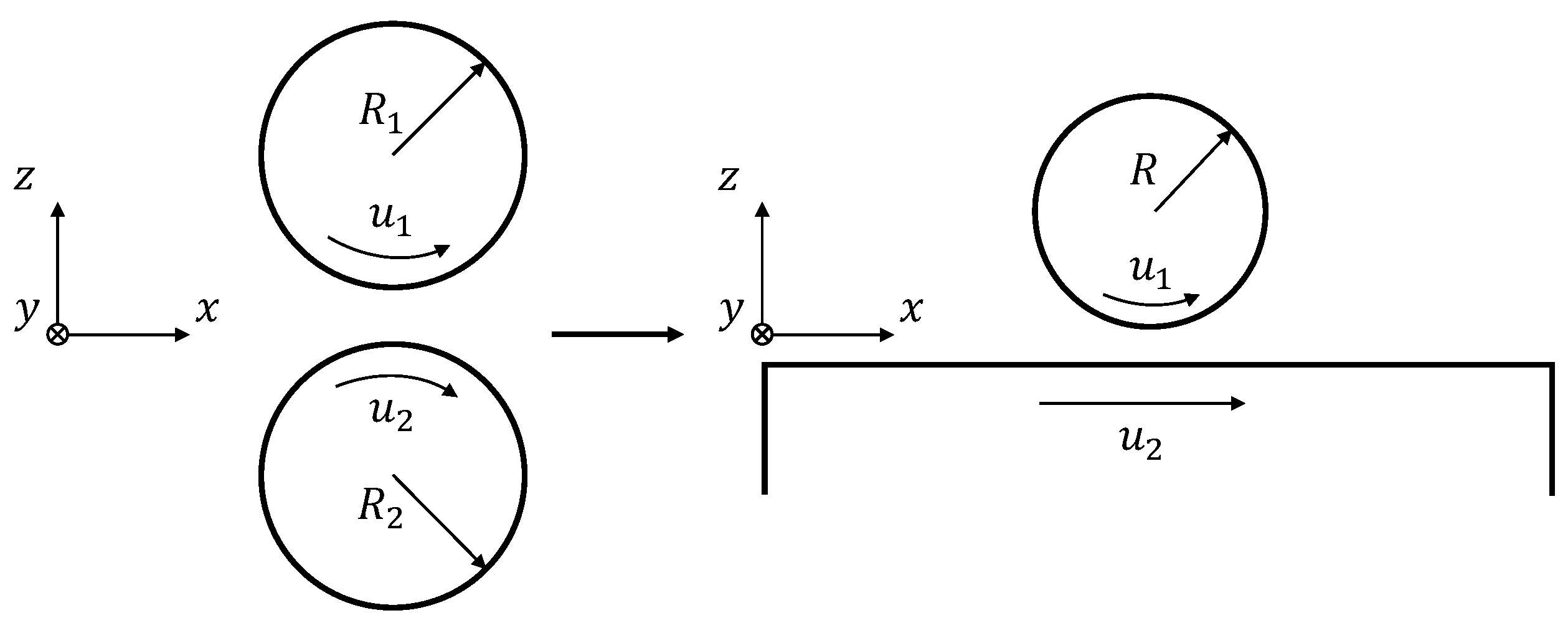
2.1. Elastohydrodynamic Model

A generalised Reynolds equation that enables the study of a varying lubricant behaviour across the film thickness, related to non-Newtonian behaviour and thermal effects, was presented by Dowson [57] and improved by Yang and Wen [58]. This equation governs the lubricant pressure distribution within the EHL contact and reads:
x η e ρ e η e ρ e p x = ρ * x + ρ e t ,
with the parameters describing the effective density and viscosity, based on the variations throughout the lubricant film, being written as follows:
ρ * = ρ e η e u 1 u 2 + ρ e u 2 , ρ e = 0 h ρ d z , ρ e = 0 h ρ 0 z d z η d z , ρ e = 0 h ρ 0 z z d z η d z , 1 η e = 0 h d z η , 1 η e = 0 h z d z η .
Moreover, the lubricant velocity throughout the film in the entrainment direction is written as:
u f ( x , z ) = u 2 + p x 0 z z d z η η e η e 0 z d z η + η e u 1 u 2 0 z d z η .
To solve the generalised Reynolds equation, knowledge about the viscosity and density behaviour over the film thickness becomes essential, which are affected not only by the pressure and the shear stress in the lubricant, but also by the heat distribution. Thereby, the energy dissipation and heat distribution in the lubricant film have to be solved properly, which is detailed in Section 2.2. Additionally, the lubricant film thickness in-between the contacting surfaces, h ( x , t ) , has to be calculated and can be described according to:
h ( x , t ) = h 0 ( t ) + x 2 2 R + | w | + R 1 ( x , t ) + R 2 ( x , t ) ,
where the deformation in z-direction, w, may be found by utilising linear elasticity in combination with a plain strain approach due to the assumed infinite line contact. Moreover, a quasi-static response of the solids may be employed due to the difference in characteristic times between the EHL problem and elastic problem [59] and, in order to reduce the problem to only one deforming body, the equivalent elasticity approach may be utilised [45]. This further results in the stress equilibrium within the solid bodies to be formulated according to:
· σ = 0 ,
where the stress tensor based on the strains in the material reads:
σ x x σ z z τ e , x z = c 1 c 2 0 c 2 c 1 0 0 0 c 3 x 0 0 z z x u w ,
and the parameters c 1 , c 2 and c 3 defines the equivalent material properties. For more details, the reader is referred to [45,51].
The surface features were in this work described in a manner that results in smooth profiles with no sharp corners [6,51]. The surface feature being located on the surface, i, was described according to:
R i x , t = A R , i · 10 10 x x R , i λ R , i 2 ,
with the position of the surface feature changing in time according to:
x R , i = x 0 , i + u i t .
In the case of studying sinusoidal roughness, the roughness was only applied to one surface and hence described according to:
R 1 x , t = A R , 1 cos 2 π λ R , 1 x x R , 1 ,
again with the roughness moving through space in time according to Equation (10).
The load balance between the applied load and the lubricant pressure was assumed to behave quasi-statically due to the stiffness of the lubricant film. This implies relatively small variations in film thickness also for relatively large rigid body movements [60]. These variations were assumed to be small enough to not affect the inlet of the contact significantly and thereby the film thickness negligibly. The load balance was therefore written according to:
Ω c p ( x , t ) d x = F .
Finally, the cavitation model proposed by Wu [61] and employed by Habchi [45] was utilised in this work. This approach was employed due to its relatively simple implementation and fulfilment of the Reynolds boundary conditions. It is also assumed sufficiently accurate since lubricant film reformation does not need to be considered in this work.

2.2. Thermal Model

The heat generation and dissipation within the lubricant film and the solids were computed using the the energy equation. Assumptions reducing the equations based on the thin lubricant film as well as the infinitely long contact were employed [45]. In the lubricating film, convection and conduction in combination with heat generation from compression and shear governs the heat distribution, which are written according to:
x k l u b T x z k l u b T z + ρ c l u b T t + u f T x = Q ,
with the heat source from compression and shear following:
Q = T ρ ρ T p t + u f p x + η u f z 2 .
The heat dissipation within the solids can be described by the convection and conduction alone since no heat is generated within the solids themselves, resulting in the energy equation being written, for each solid, i, according to:
x k i T x z k i T z + ρ i c i T t + u i T x = 0 .
For more details about boundary conditions the reader is referred to, for example, References [48,49,51].

2.3. Lubricant Properties

The lubricant pressure, temperature and shear response was described in the same manner as explained in Reference [51], where the Tait equation of state (EoS) was utilised to describe the compressibility-pressure-temperature behaviour. A Vogel-like approach was employed for the viscosity-pressure-temperature dependency and a shifted Carreau model for the shear thinning behaviour of the lubricant. These equations with the corresponding input data are presented below and has reportedly been used to describe the pressure-shear-temperature behaviour of Squalane relatively successfully [62,63].
The Tait EoS describes the compressibility-pressure behaviour of the fluid according to:
V V 0 = 1 1 1 + K 0 ln 1 + p 1 + K 0 K 00 exp β K T .
The compressibility-temperature variations are described by the ratio between the volume at ambient pressure and the volume at reference temperature, which is assumed to follow a linear relationship according to:
V 0 V r = 1 + a v T T r .
By using K 0 = 11.74 , a v = 8.36 · 10 4 K 1 , K 00 = 8.658 GPa and β K = 6.332 · 10 3 K 1 , the density variations of Squalane [63] may be calculated according to:
ρ p , T = ρ r V V r 1 = ρ r V V 0 V 0 V r 1 .
The viscosity-pressure-temperature relationship describing the Newtonian viscosity behaviour, assumed to follow a Vogel-like relationship [62], reads:
μ p , T = μ exp B F φ φ φ ,
where the scaling parameter, φ , is dependent on the temperature and compressibility variations according to:
φ = T T r V V r g .
Using Equations (19) and (20), the Newtonian viscosity-pressure-temperature response of Squalane may be found by using g = 3.921 , φ = 0.1743 , B F = 24.50 and μ = 0.9506 · 10 4 Pa s .
The non-Newtonian shear thinning behaviour of the lubricant that was assumed to follow a shifted Carreau model may be written according to [62]:
η p , T , γ ˙ = μ 1 + γ ˙ λ r μ μ r T r T V V r 2 n 1 / 2 ,
where the shear rate is calculated according to:
γ ˙ = γ ˙ x z 2 = u f z ,
and the use of μ r = 15.6 mPas , λ r = 2.26 · 10 9 s , and n = 0.463 describes the shear thinning response of Squalane [62,64]. Note, however, that the shear stress was not limited by the function Λ p in this work.
Lastly, the thermal conductivity and volumetric heat capacity variations due to pressure and temperature were described according to [62]:
k l u b = C k V V r s 1 + A T T r V V r q s ,
and
C l u b = ρ c l u b = C 0 + m T T r V V r 3 ,
respectively. By using q = 2 , A = 0.115 , C k = 0.074 Wm 1 K 1 , s = 4.5 , C 0 = 0.94 MJ m 3 K 1 and m = 0.62 MJ m 3 K 1 , the variations experienced by Squalane may be found [62].

2.4. Numerical Approach

The finite element (FE) numerical approach, including boundary conditions, weak formulations and implementation employed in this work, is thoroughly described in Hultqvist et al. [51] and therefore not repeated here. However, the main features are briefly described and modifications made in this work are highlighted below.
The transient TEHL problem was solved in a weakly coupled manner between a fully coupled EHL FE model and a thermal FE model using commercial software [65,66]. The two models were set up based on the work by Habchi [45] and the transient approach having features based on the work by Lohner et al. [49]. However, a major difference in solving the transient problem is employed where the full time dependent solution was solved at every iteration in the solution procedure, allowing for utilisation of numerical solvers in the commercial FE software [65], see Hultqvist et al. [51].
Moreover, the thermal model was in this work stabilised by the streamline upwind Petrov-Galerkin (SUPG) approach, see for example, Habchi [56]. The mesh was allowed to vary in element size along the entrainment direction in both the EHL model and thermal model, allowing for a similar accuracy to be achieved for a reduced number of degrees of freedom, leading to a reduced solution time compared to Reference [51]. Expressed in the dimensionless parameter X = x / a , the element size outside the high pressure region was set to 0.01 , that is, for 4.5 X 1.5 and 1.5 X 2.5 , while being set to 0.005 for the area comprising the high pressure region, that is, 1.5 X 1.5 . In the thermal model, the film thickness height was discretised using an element size of 0.05 , expressed in the dimensionless parameter Z = z / h . The transient solver used a backward differential formulation with an order 2 for the EHL model and an order varied between 1–5, adjusted to achieve the specified tolerances, for the thermal model.

3. Results and Discussion

The input data related to material properties of the contacting solids, contact parameters and operating conditions were chosen to represent a typical non-conformal contact found in for example, a rolling element bearing or mating gear teeth. However, relatively high sliding conditions were assumed in order to enlarge the effects related to sliding in the contact. For rolling conditions, shear thinning and thermal effects may be neglected [51], meaning that due to the small effect of compression on heat generation in EHL contacts [67], an isothermal Newtonian approach is a reasonable assumption and therefore such conditions are not studied in this work. The data used for this study are presented in Table 1 and were used in all simulations for straight forward comparison between the results.
Note that the material data in Table 1 describes a typical steel and may therefore not accurately describe the thermal properties of a hardened steel, which is typically used in the aforementioned applications. However, the influence of hardening on for example, the thermal conductivity was out of scope for this study and assumed to not influence the qualitative behaviour of the studied phenomena significantly.
The results are presented in two parts, first studying how sinusoidal roughness behaves within a thermal EHL contact, where focus lies on the differences between a thermal non-Newtonian approach and an isothermal Newtonian approach for various roughness wavelengths. Thereafter, the thermal EHL model is used to study different surface features that overtakes within the contact as well as different overtaking positions for one specific surface feature combination. For comparison, the smooth contact solutions for both the thermal non-Newtonian approach and the isothermal Newtonian approach are shown in Figure S1. Moreover, the results and input parameters are in this section expressed in dimensionless form using normalisation based on the following reference parameters and Hertz theory:
X = x a , H = h R a 2 , A ¯ R , i = A R , i R a 2 , Λ R , i = λ R , i a , R i ¯ = R i R a 2 , P = p p h , Θ = t u e a , T ¯ = T T r , η ¯ = η μ r ,
where a and p h are the Hertzian dry contact parameters [68].

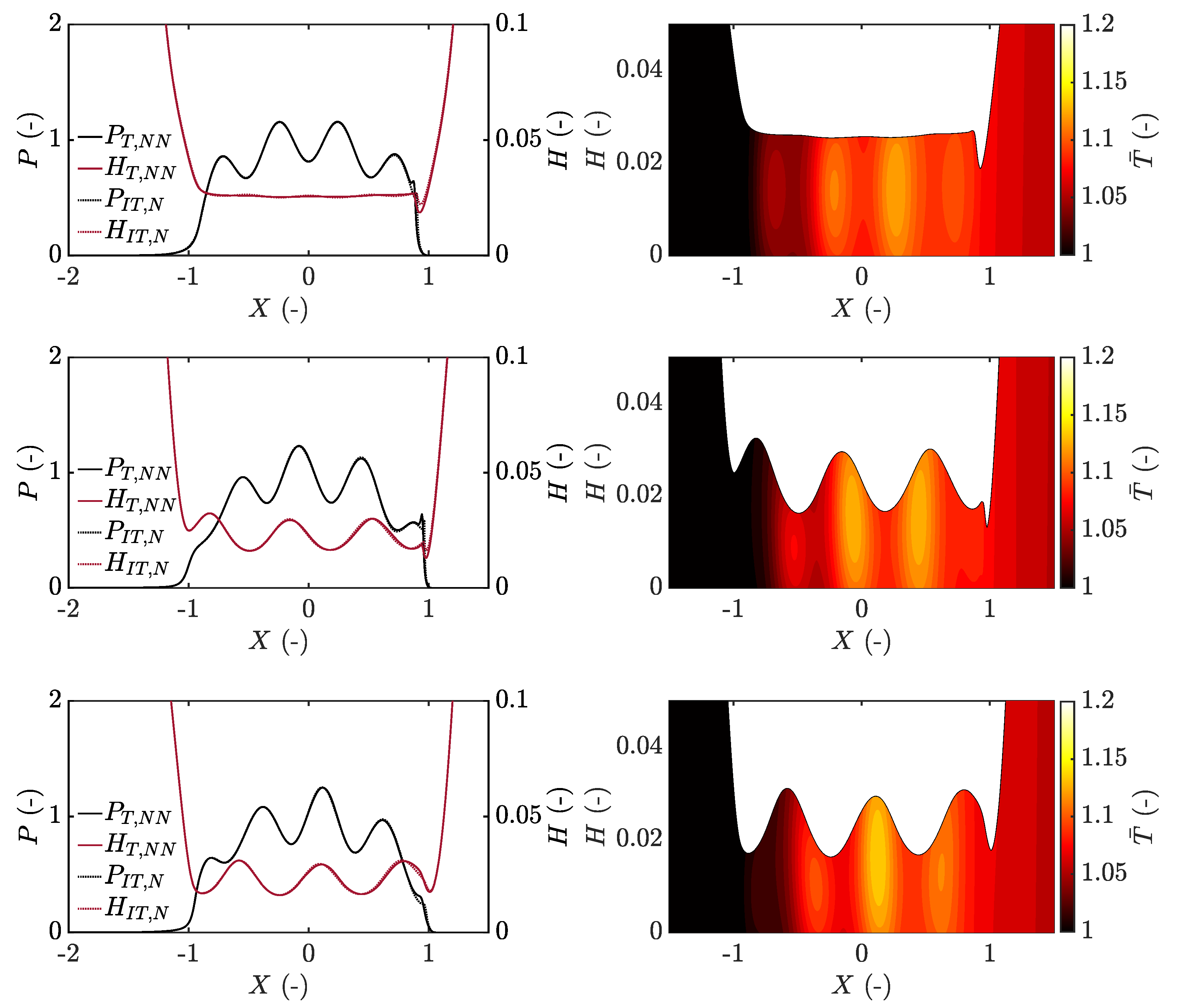
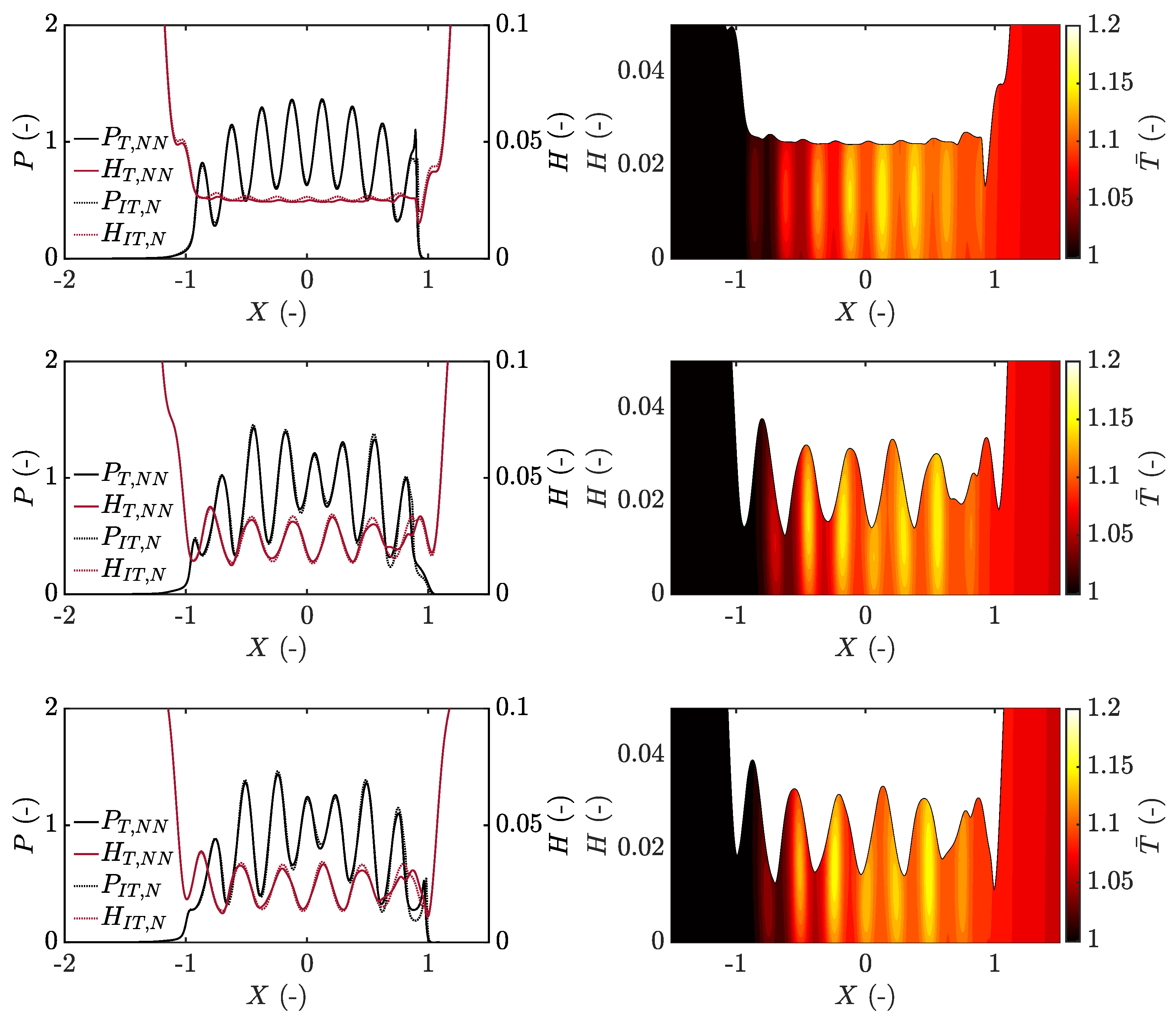
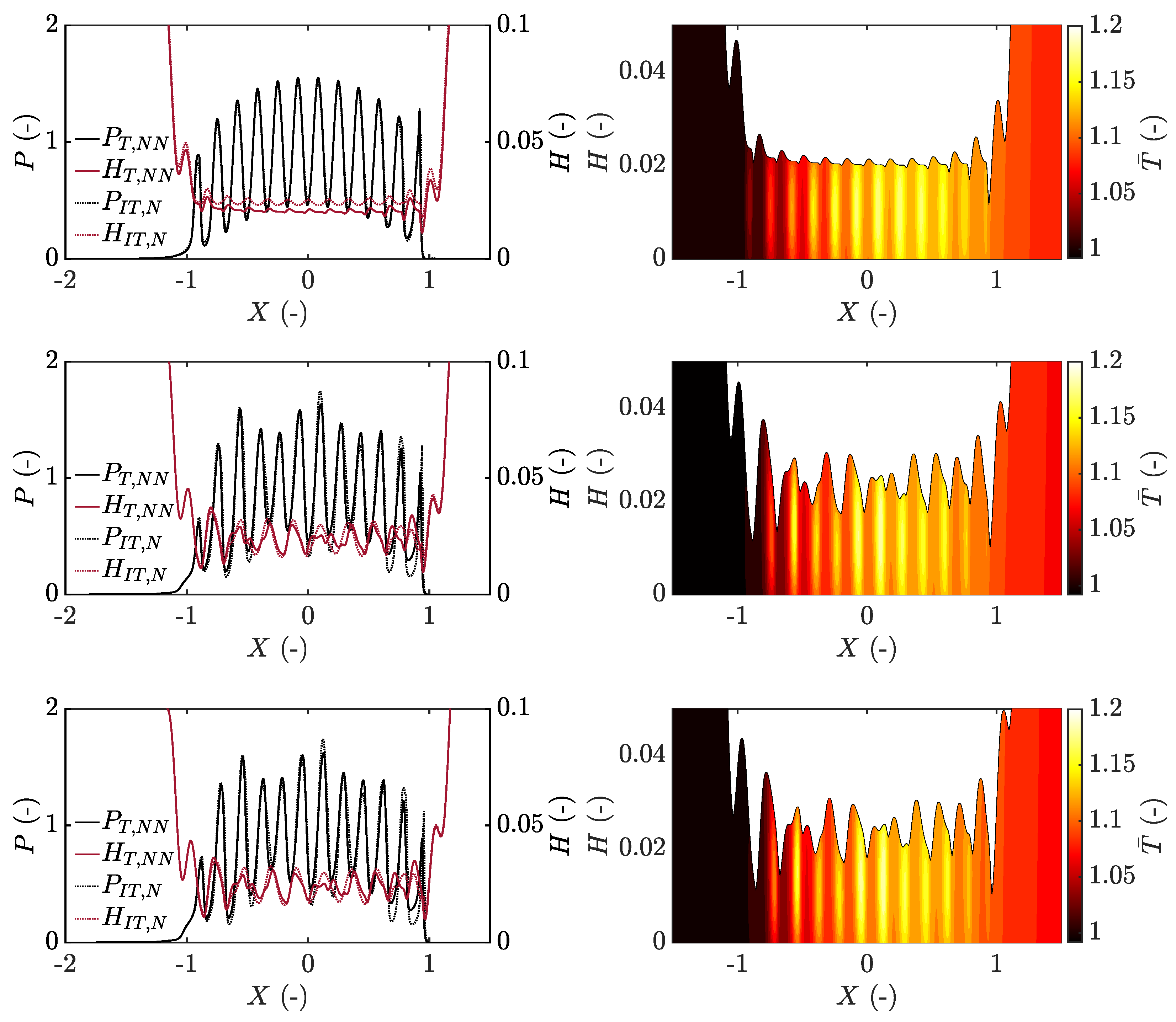
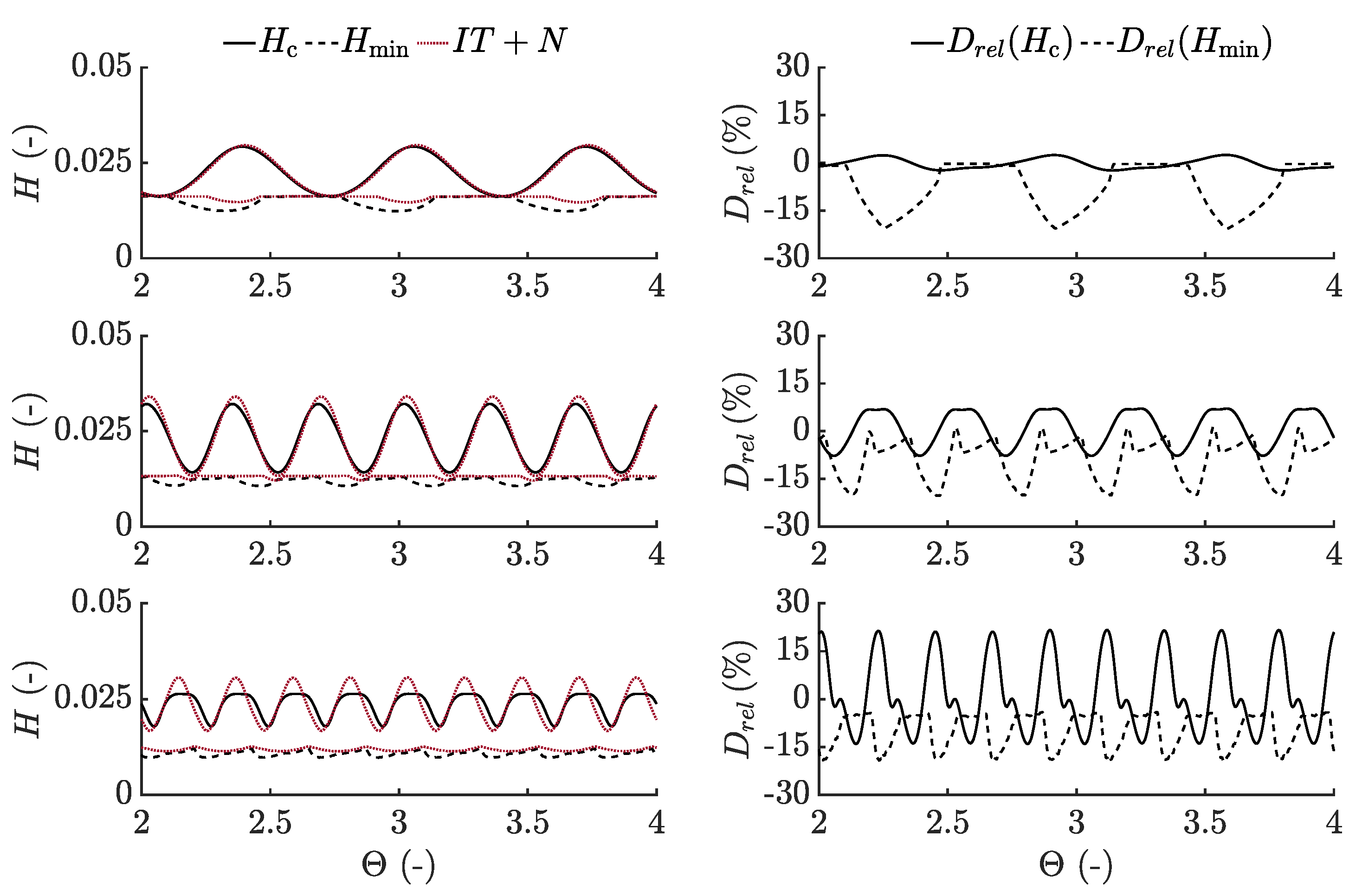
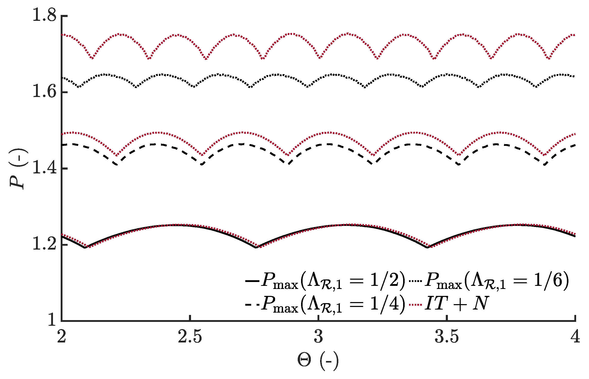
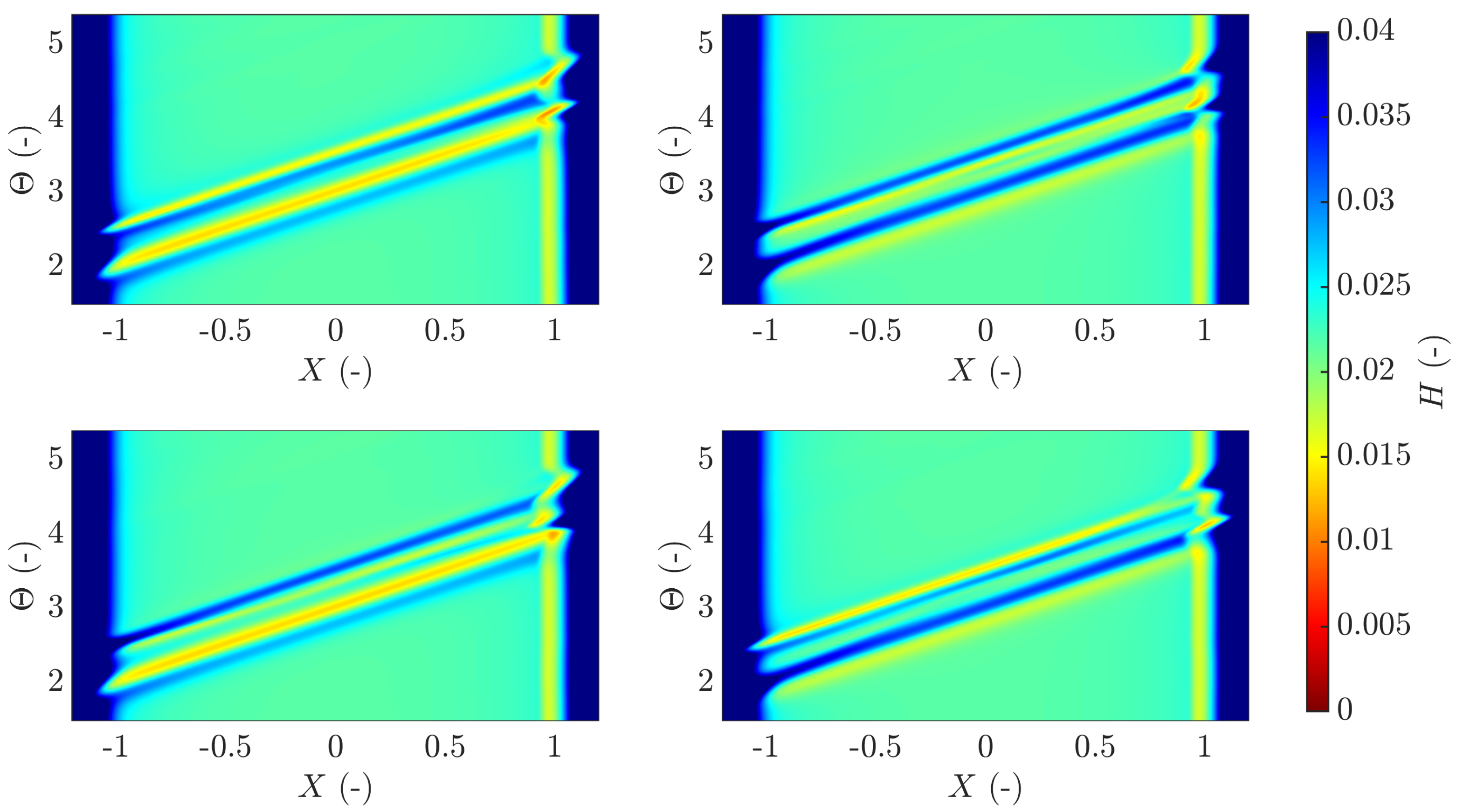
3.1. Sinusoidal Roughness

A comparison between the developed thermal non-Newtonian approach and an isothermal Newtonian approach was conducted for three different types of roughness. The roughness was sinusoidal according to Equation (11) and located on the slower surface, that is moving with speed u 1 = 0.75 m s 1 . For all sinusoidal waves, a fixed dimensionless amplitude of A ¯ R , 1 = 0.015 was used, however, with the dimensionless wavelength being varied between Λ R , 1 = 1 / 2 , Λ R , 1 = 1 / 4 and Λ R , 1 = 1 / 6 , shown in Figure 2. This further implies that approximately 4, 8 and 12 waves were located inside the contact at one moment, respectively. A real surface is, however, made up of a complete spectrum of wavelengths that could possibly include all the aforementioned wavelengths and others, at once. However, in order to further understand the influence of wavelength on the lubricating mechanisms and film formation, this study was limited to the behaviour of the aforementioned separate wavelengths at a fixed amplitude.
Initially, the case with the longest wavelength was studied, that is, Λ R , 1 = 1 / 2 . It was seen that the long wavelength roughness was generating a relatively smooth pressure profile with pressure ripples being directly connected to the peaks and valleys of the sinusoidal roughness, see Figure 3. The amplitude of the roughness within the contact was seen to deform significantly, as shown by the steady state solution used as initial conditions to the time dependent problem, that is, at Θ = 0 . The steady state solution shows the film thickness and pressure associated with the deformed roughness within the contact due to the exclusion of time dependency and thereby also any inlet generated effects. This is commonly referred to as the particular integral [21] and dominates the pressure in the contact, however, with a small influence on the film thickness due to the significant roughness deformation within the contact.
Considering the transient solution, the roughness can be seen to be deformed noticeably less in the inlet of the contact and does, due to the viscosity magnitude, generate inlet perturbations that are formed somewhere in between 1 X 0.5 in what Morales-Espejel [23] refers to as the Couhier region based on the work by Couhier [69]. The amplitude of these inlet perturbations is noticeably smaller than the initial roughness amplitude and travels through the contact at the mean entrainment speed, u e . Moreover, these perturbations are wider than the wavelength of the roughness profile, which is explained by the negative slide-to-roll ratio in this case. Further meaning that the rough surface moves slower than the mean speed of the lubricant and thereby generates inlet perturbations with a wavelength of Λ = Λ R u e / u 1 due to the flow into the contact being limited by the roughness [21,38]. These inlet perturbations are commonly referred to as the complementary function and are, as opposed to the particular integral, related to small pressure variations but dominates the film thickness fluctuations.
The temperature is seen to vary in direct relation to the roughness profile and is explained by the viscosity variations of the sheared lubricant due to the pressure variations, which thereby influences the shear heating [51]. A very good agreement related to both pressure and film thickness between the isothermal Newtonian approach and the thermal non-Newtonian approach can, for the case Λ R , 1 = 1 / 2 , be observed. However, with a significantly reduced film thickness during exiting of deformed roughness peaks for the thermal non-Newtonian approach, seen at for example, Θ = 2.25 in Figure 3. This is related to the reduced viscosity of the lubricant due to inlet shear thinning and shear heating, which leads to a further reduced viscosity and hence an increased pressure driven flow in the contact outlet (see Figure S2).
A smaller wavelength of Λ R = 1 / 4 shows significantly increased pressure ripple magnitudes compared to the previously studied wavelength. Here a reduced, but still almost complete, roughness deformation occurs within the contact as again seen by the steady state solution, see Figure 4. The amplitude of the complementary function is, however, slightly larger due to a reduced deformation of the roughness in the inlet.
Furthermore, an increased amount of heat is generated due to the increased number of pressure peaks in combination with their increased magnitude. As can be seen in the temperature plots, the thermal effects also affect the film formation within the Couhier region and thereby the formation of the complementary function, which is especially visible for Θ = 2.25 in Figure 4.
A discrepancy between the thermal non-Newtonian solution and the isothermal Newtonian solution is starting to appear, which is not only visible in the outlet of the contact but also slightly within the high pressure region. This is explained by a reduction of the complementary function due to a reduced viscosity in the inlet region. A decay of the complementary function throughout the contact has previously been highlighted by, for example, Hooke [30] and Hooke and Morales [32,33]. This decay does, however, only seem to take place in the Couhier region for the case of Λ R , 1 = 1 / 4 , where the complementary function reduces as it passes through low viscosity regions connected to valleys on the surface roughness in this case, seen by the amplitude difference between the waves in-between approximately 0.8 X 0.4 at Θ = 2.5 in Figure 4. This is related to a reduced viscosity from shear thinning and shear heating in the case of the thermal non-Newtonian approach, which further leads to a difference between the two solutions. However, when the complementary function has passed further into the high pressure region, it moves through the rest of the contact relatively unaffected.
Moreover, it is interesting to note that the complementary function slightly increases in amplitude when passing through localised high pressure regions related to the surface roughness. This is explained by the density increase that further leads to a locally reduced film thickness as discussed by Venner and Bos [70]. The aforementioned effects become increasingly visible with a reduced wavelength of the waviness.
With a further reduced wavelength of the sinusoidal roughness using Λ R = 1 / 6 , the pressure ripple magnitude as well as the number of pressure spikes within the contact increases further. This implies that the contact inlet becomes increasingly affected by fluctuations and thereby the formation of the complementary function is influenced to an increased extent, as can be seen in Figure 5.
Due to the increased number of waves, the complementary function has time to pass through more roughness valleys with low viscosity already in the Couhier region, see Figure 6, which is seen to reduce the amplitude of the complementary function. The initially formed complementary function hence reduces in amplitude each time it passes through a low viscosity region and does basically vanish in the first half of the contact.
This occurs even though the lubricant flow is dominated by Couette flow throughout the contact in each of the studied cases (see Figure S3) and becomes increasingly pronounced for the thermal non-Newtonian approach because of the reduced viscosity connected to the roughness peaks in the inlet region following shear thinning and shear heating (see Figure S2). Moreover, In the second half of the contact, the film thickness reductions are seen to be directly connected to the temperature and viscosity variations, and thereby also the pressure and roughness itself, as can be seen in-between approximately 0.5 X 0.8 in Figure 5 at Θ = 2.25 and Θ = 2.5 . This indicates that the complementary function effect has been fully reduced.
To further study the differences between the thermal non-Newtonian solution and the isothermal Newtonian solution, the central and minimum film thickness values over time were extracted for each case analysed, see Figure 7. The relative difference between the two approaches is also visualised and was calculated according to:
D r e l = H m i n , T + N N H m i n , I T + N H m i n , I T + N .
It can be seen that in the case of the complementary function defining the film formation throughout the contact, for example, in the case of Λ R , 1 = 1 / 2 , the difference between the thermal non-Newtonian and isothermal Newtonian approaches is negligible in the central region of the contact. However, in the outlet the solutions differ due to a reduced viscosity from the inlet shear thinning and shear heating. This does not seem to affect the central region due to the solidified behaviour of the entrapped lubricant, but does lead to an increased pressure driven flow when the pressure again drops in the outlet. With a reduced wavelength, however, the reduced amplitude of the complementary function leads to a discrepancy between the two approaches also in the central region due to viscosity differences in the Couhier region that influence the formation of the complementary function, which becomes increasingly pronounced for shorter wavelengths.
For the shortest wavelength studied in this work, the relative difference between central film thickness fluctuates between approximately 20 % and 14 % as a consequence of both the decaying complementary function and the compressibility-pressure-temperature dependency of the lubricant. Moreover, the minimum film thickness is overestimated by approximately 20 % during exiting of the deformed roughness as a result of reduced lubricant viscosity due to an increased temperature and the non-Newtonian lubricant behaviour.
This highlights the importance of applying a thermal non-Newtonian approach to accurately predict the film thickness behaviour within the high pressure region for short wavelength roughness, whereas for longer wavelength roughness the difference in the high pressure region is not as significant. Moreover, it is interesting to note that the largest difference in minimum film thickness is approximately the same for all studied wavelengths, and only slightly larger compared to the smooth contact case (see Figure S1). This implies that the minimum film thickness is not significantly affected by the local variations within the contact, but instead mainly dependent on the variations within the Couhier region, which further leads to a reduced outlet film thickness due to an increased outlet flow for the thermal non-Newtonian solution.
For the sake of completeness, the maximum pressure within the contact was compared between the three cases, see Figure 8. Due to the relatively small pressure fluctuations related to the complementary function [12,21], a less significant difference is seen compared to the film thickness variations. Nevertheless, as an effect of the reduced complementary function in the Couhier region, the pressure ripples reduce in magnitude within the contact, especially while considering thermal non-Newtonian effects, which further implies that the combined pressure component from the particular integral and the complementary function reduces for cases with shorter wavelengths.
The results from this section show that for long wavelength roughness, the temperature and non-Newtonian lubricant behaviour have an effect on minimum film thickness in particular. It is thus important to make use of a thermal model in the study of two-sided surface features, which is presented in the next section.

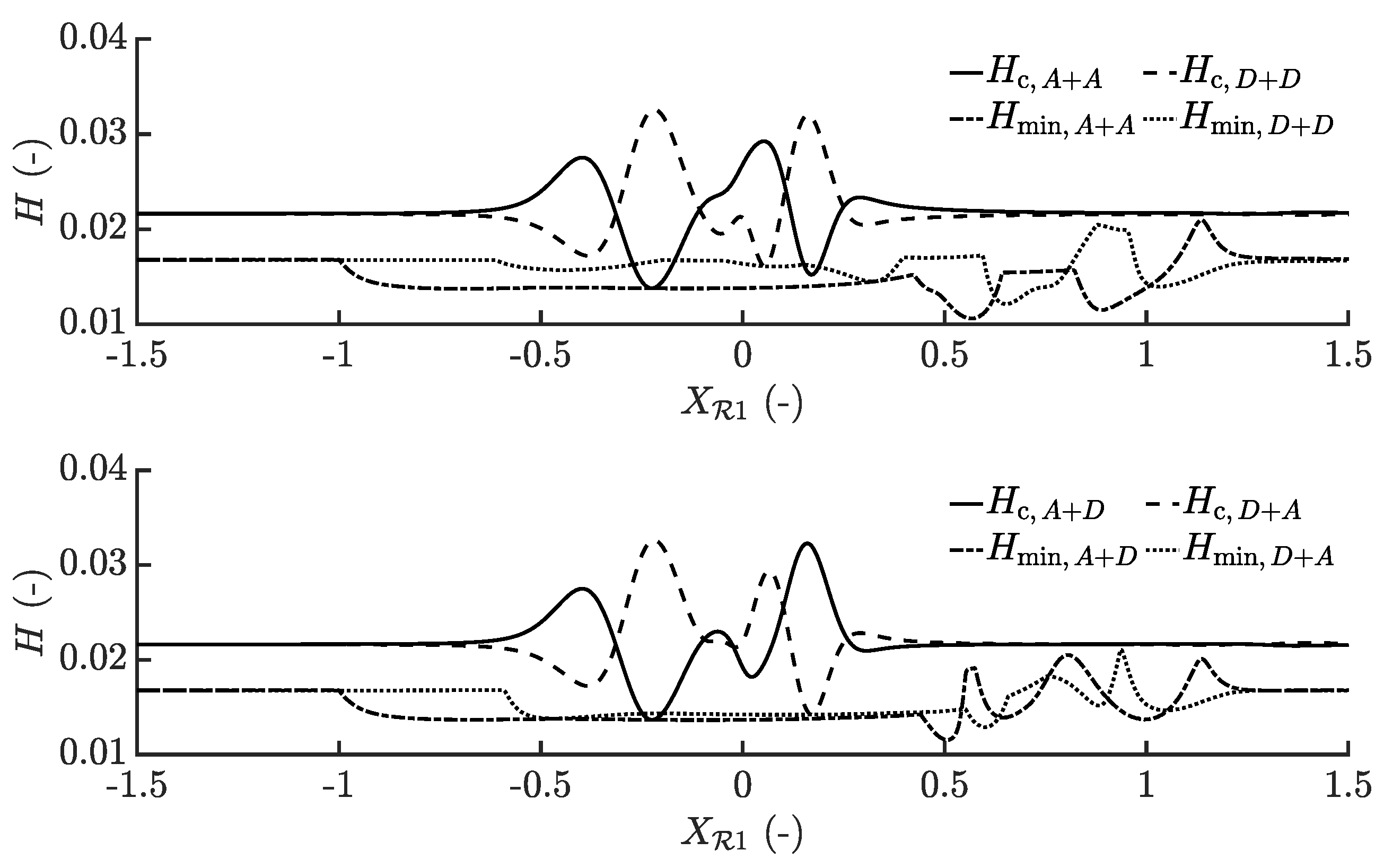
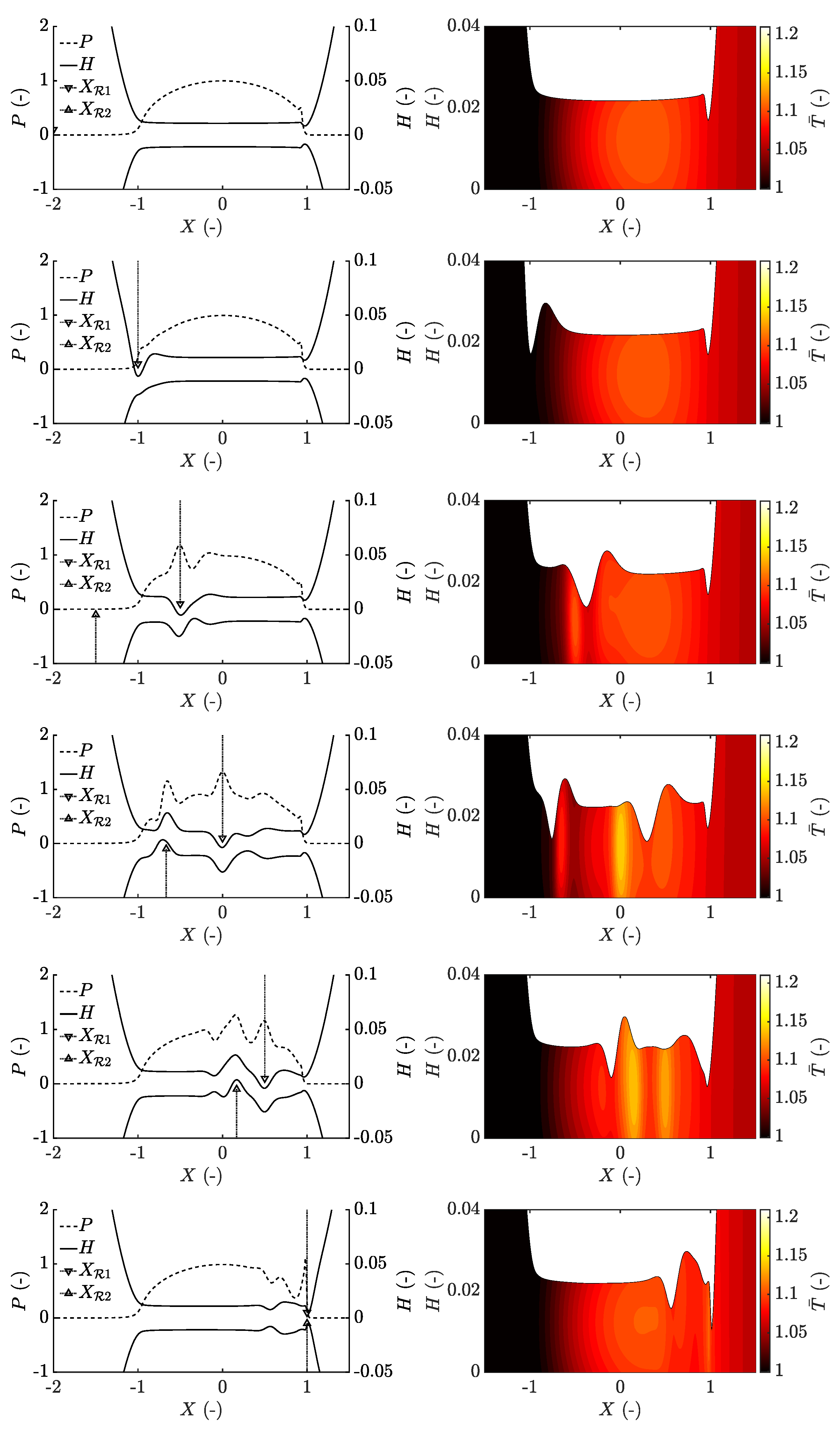
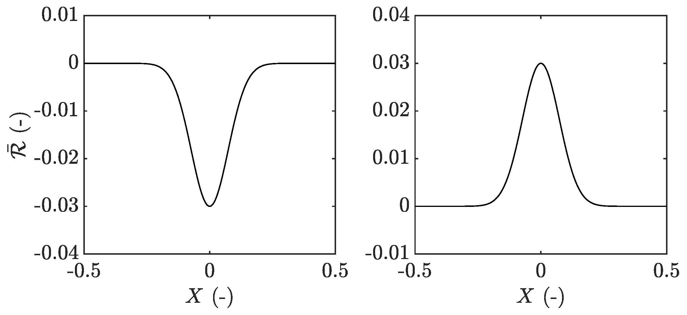
3.2. Two-Sided Surface Features

The study of two-sided surface features was conducted using surface features with twice the amplitude compared to the aforementioned sinusoidal roughness, that is, A ¯ R , i = ± 0.03 . Moreover, a wavelength of Λ R , 1 = Λ R , 2 = 0.5 was employed, resulting in the surface features shown in Figure 9.
The surface features were at first chosen to meet and completely overlap in the middle of the contact, that is the point of interference occurred at X = 0 . The point of interference was later changed to X = 1 and X = 1 , which is covered later in this section. The upper surface was moving slower at a speed of u 1 = 0.75 m s 1 and the lower surface moving faster with u 2 = 1.25 m s 1 . An overlap at X = 0 was achieved by setting the initial positions of the surface features to X 0 , 1 = 2.5 and X 0 , 2 4.17 . Four different combinations of overtaking situations were studied based on the work by Almqvist [55], which were defined as follows:
  • an asperity on the slower surface overtaken by an asperity on the faster surface ( A + A ),
  • a dent on the slower surface overtaken by a dent on the faster surface ( D + D ),
  • an asperity on the slower surface overtaken by a dent on the faster surface ( A + D ),
  • a dent on the slower surface overtaken by an asperity on the faster surface ( D + A ).
The case of two asperities overtaking, that is, the case A + A , is shown in Figure 10. Note that the split film thickness values in the left column are defined as half the combined geometry and half the combined deformation with the corresponding surface feature added, as defined by Morales-Espejel [23]. In the case of the contacting bodies having the same material properties, the split film thickness is defined according to:
S u p p e r = H R ¯ 1 R ¯ 2 2 + R ¯ 1 , S l o w e r = H R ¯ 1 R ¯ 2 2 + R ¯ 2 .
This improves visualisation of the problem and implies that the distance between S u p p e r and S l o w e r represents the film thickness H, which is shown in the right column in the figure together with the temperature field.
It can be seen that a complementary function is generated in the inlet based on the deformation of the surface feature in the Couhier region, similar to that of long wavelengths in Section 3.1. The complementary function moves with the mean entrainment speed and hence start to de-attach from the corresponding surface feature, which itself is significantly deformed. Moments thereafter, the other, faster, surface feature enters and generates another complementary function, smaller in size due to the increased speed, which implies a shorter time of inlet disturbance. This complementary function again moves with the entrainment speed and hence moves parallel in time with the first complementary function, indicating that the film thickness disturbances do not experience any interference.
Moreover, with the pressure and temperature being directly connected to the position of the surface features, as opposed to the complementary function, these values vary noticeably during the overtaking event and reaches their maximum values at X R 1 = X R 2 = 0 . A similar behaviour was also seen for the case of two dents overtaking at X = 0 , that is, the case D + D . However, the dents generate a complementary function in the form of a film thickness increase, as shown in Figure S4. Additionally, a significant pressure drop rather than a pressure spike occurs when the two dents overlap at X R 1 = X R 2 = 0 .
In the case of a dent overtaking an asperity within the contact, that is, the case A + D , a similar behaviour of the complementary functions compared to the previously studied cases is seen, shown in Figure 11. Here, again, the formation of the complementary functions in the inlet moves through the contact with the mean entrainment speed. However, the pressure is experiencing negative interference as opposed to the cases A + A and D + D , meaning that at X R 1 = X R 2 = 0 an almost completely smooth pressure profile is seen and only small pressure ripples related to the complementary functions remain.
This further highlights that the influence on pressure from the complementary function is small in comparison to the particular integral. Consequently, the temperature is not as affected in this case due to the reduced amount of shear heating that is generated. A similar behaviour is seen for the case of a dent being overtaken by an asperity, that is, the case D + A , shown in Figure S5.
The film thickness values for all four cases are shown in Figure 12. It becomes clear that the two complementary functions formed in the inlet travel with the same speed throughout the contact in each of the studied cases, meaning that the film thickness variations are basically independent of each other. The width difference related to the time spent by the surface feature travelling through the contact inlet also becomes visible, which due to the limited flow into the contact results in an increasingly wide complementary function for the slower moving asperity. Moreover, only relatively small film thickness fluctuations are seen in-between the complementary functions that are related to the roughness deformation and hence the particular integral. It may also be seen that the thinnest film occurs in the outlet of the contact, which is especially pronounced for the case when an asperity exits the contact.
Further studying the minimum film thickness over time between the cases reveals that the case A + A results in the thinnest film, followed by the case A + D , see Figure 13. The differences in minimum film during exiting of the surface features for the individual cases studied are explained by the combined exit of the faster surface feature with the complementary function of the slower surface feature, which occurs when the slower surface feature is located at X R , 1 0.5 . The second significant film reduction taking place at X R , 1 0.9 is related to the exiting of the sole, slower, asperity. A similar behaviour can be seen for all four cases. Furthermore, it is interesting to note that the exiting of a dent in combination with the complementary function of an asperity gives a thinner minimum film thickness than that of an asperity exiting together with the complementary function of a dent, as shown by the differences between the cases A + D at X R , 1 0.5 and D + A at X R , 1 0.6 .
Moreover, as noted before, the pressure is to a great extent related to the particular integral solution and thereby the surface feature itself. Hence, the two particular integrals interfere within the contact as opposed to the complementary waves, see Figure 14. This means that in the cases A + A and D + D , constructive interference between the particular integrals occurs and leads to a maximum and minimum pressure, respectively, when the surface features are located at X R 1 = X R 2 = 0 . The same also applies to the cases A + D and D + A , however, with negative interference leading to an almost smooth pressure profile at X R 1 = X R 2 = 0 . Only small pressure perturbations occurs away from the main pressure fluctuations, which are related to the complementary functions. The maximum pressure values over time are shown in Figure S6.
After studying the four different surface feature combinations overtaking at X = 0 , a change of position was considered and applied to the case A + A . Now, the overtaking between the two asperities was set to occur at the outlet of the contact, implying that the complete overlap of the asperities takes place at X = 1 . This reveals similar mechanisms as discussed above for the case of overlap at X = 0 , that is, the complementary functions are formed in the inlet and moves parallel to each other throughout the contact, as shown in Figure 15. Additionally, due to the significant influence of the surface features on the outlet film thickness, the minimum film thickness becomes noticeably reduced during exiting of the two asperities together compared to the previously studied case. This is explained by the increased pressure driven flow related to the combined asperity exiting event.
An additional change of overtaking position was also studied, that is, considering a complete overlap of the asperities at the inlet at X = 1 . This revealed that in the case of overtaking occurring in the inlet, a combined inlet restriction from the two overlapping asperities occurs. Further implying that the complementary functions overlap and results in a single, combined, complementary function that moves through the contact at the mean entrainment speed, shown in Figure S7. The pressure does in this case, however, never experience interference due to the constant separation of the surface features throughout the contact.

4. Conclusions

In this work, an investigation of the rough thermal EHL problem was conducted using a previously developed thermal EHL model. The investigation was made up by two main analyses, one with focus on sinusoidal roughness and the differences between a thermal non-Newtonian approach and an isothermal Newtonian approach in the context of film formation with respect to the deformed roughness component and the generated inlet perturbations, also referred to as the particular integral and the complementary function, respectively. The other was focused on the transient event of two-sided surface features overtaking within the thermal EHL contact.
The general idea of the study was to learn more about rough EHL and the mechanisms of film formation. It was expected that thermal effects would make the minimum film thickness smaller than in the corresponding isothermal analysis. The results show that thermal effects must be taken into account when accurate values of minimum film thickness are sought for. The study can also be seen as a way to further investigate the mechanisms of film breakdown. Local thermal effects may lead to a reduction of viscosity that allow for asperities to grow out of their deformed state and thus causing metal-metal contacts. It is, however, not possible to estimate breakdown from the results presented here. Future studies of shorter wavelength roughness and a more pressure sensitive lubricant may potentially provide more information on mechanisms affecting film breakdown.
The salient conclusions from this study can be summarised as follows:
(i)
In case of sinusoidal roughness, differences in outlet film thickness between the thermal non-Newtonian and isothermal Newtonian approaches were for all studied wavelengths observed. These differences were explained by a reduced viscosity in the contact inlet due to shear thinning and shear heating, and further resulted in the isothermal Newtonian approach to overestimate the minimum film thickness by up to 20 % .
(ii)
Differences in the high pressure region were only found to be significant in case of short wavelength roughness. These differences were explained by a reduced viscosity in the contact inlet due to shear thinning and shear heating, further disturbing the formation of the complementary function. This resulted in central film thickness estimations to differ between 20 % and 14 % by using the thermal non-Newtonian approach compared to the isothermal Newtonian approach.
(iii)
Following the relatively small influence on pressure by the complementary function, only small differences in maximum pressure between the thermal non-Newtonian and isothermal Newtonian approaches were noticed.
(iv)
In case of two-sided surface features overtaking within the contact, it was found that an interference between the film thickness perturbations did not occur due to the complementary function being generated in the inlet of the contact and travelling with the speed of the lubricant. On the other hand, due to the particular integral being directly connected to the roughness feature, an interference between the pressure and temperature variations were obvious.
(v)
In case of the overtaking event occurring in the inlet of the contact, one single complementary function was formed with larger amplitude than the other cases. Moreover, if overtaking instead took place in the outlet of the contact, a significantly reduced film thickness was noted.
(vi)
For the studied cases, it can be concluded that a thermal non-Newtonian approach is required for quantitatively accurate outlet film thickness predictions and may also be necessary for accurate predictions of film thickness within the contact if the complementary function is affected during formation. Otherwise, in the case of long wavelength roughness or low sliding conditions, an isothermal approach may be sufficient due to the inlet dominated film formation.

Supplementary Materials

The following are available at https://www.mdpi.com/2075-4442/8/6/64/s1.

Author Contributions

Conceptualization, T.H., A.V., P.M. and R.L.; Data curation, T.H. and R.L.; Formal analysis, T.H.; Funding acquisition, R.L.; Investigation, T.H., A.V., P.M. and R.L.; Methodology, T.H. and R.L.; Project administration, T.H., P.M. and R.L.; Resources, P.M. and R.L.; Software, T.H.; Supervision, P.M. and R.L.; Validation, T.H.; Visualization, T.H.; Writing—original draft, T.H.; Writing—review & editing, T.H., A.V., P.M. and R.L. All authors have read and agreed to the published version of the manuscript.

Funding

This research is part of the FFI-project P41215-1 funded by the Swedish Energy Agency (Energimyndigheten).

Acknowledgments

The authors wish to thank Tomas Johannesson at Volvo Car Corporation for all the fruitful discussions and valuable input to this work.

Conflicts of Interest

The authors declare no conflict of interest.

Nomenclature

AConductivity scaling parameter
A R , i Amplitude of surface roughness m
A ¯ R , i Dimensionless amplitude of surface roughness,
aHertzian contact radius m
a v Thermal expansivity K 1
B F Fragility parameter in viscosity equation
C 0 Parameter for calculation of heat capacity J m 3 K 1
C k Parameter in conductivity function W m 1 K 1
C l u b Volumetric heat capacity of lubricant J m 3 K 1
c l u b Specific heat capacity of lubricant J kg 1 K 1
c s 1 , c s 2 Specific heat capacity of upper- and lower solid J kg 1 K 1
E 1 , E 2 Young’s modulus of upper- and lower body, respectively Pa
FApplied load per unit width N m 1
G r Shear thinning parameter Pa
gThermodynamic interaction parameter
hLubricant film thickness m
h 0 Rigid body displacement m
HDimensionless lubricant film thickness
K 00 Isothermal bulk modulus at p = 0 and zero absolute temperature Pa
K 0 Pressure rate of change of K 0
k l u b Thermal conductivity of lubricant W m 1 K 1
k s 1 , k s 2 Thermal conductivity of upper- and lower solid W m 1 K 1
mParameter in heat capacity function J m 3 K 1
nShear thinning parameter
p h Maximum Hertzian pressure (1D) Pa
pHydrodynamic pressure in lubricant film Pa m
PDimensionless hydrodynamic pressure
qCoefficient in conductivity scaling parameter
REquivalent radius of curvature m
R 1 , R 2 Radius of upper- and lower body, respectively m
sExponent in conductivity model
S u p p e r , S l o w e r Visualised upper- and lower surface, respectively
S R R Slide-to-roll ratio
T , T r Temperature and reference temperature, respectively K
T ¯ Dimensionless temperature
tTime s
u , w Deformation in x and z, respectively
u e Mean entrainment velocity of lubricant m s 1
u 1 , u 2 Speed of upper- and lower surface, respectively m s 1
u f Lubricant velocity in x z -plane m s 1
VVolume of lubricant
V 0 , V r Volume of lubricant at P 0 and T r , respectively m 3
x , y , z Spatial coordinates m
x R , 1 , x 0 Current- and initial position of roughness, respectively m
X , Y , Z Dimensionless spatial coordinates
X R , X 0 Current- and initial dimensionless position of asperity, respectively m
β K Temperature coefficient K 1
η ¯ Dimensionless shear dependent lubricant viscosity
η Shear dependent lubricant viscosity Pa s
γ ˙ , γ ˙ x z Lubricant resultant shear rate and shear rate in x z -plane, respectively s 1
λ r Relaxation time at T r and ambient pressure s
λ R , i Wavelength of asperity m
Λ R , i Dimensionless wavelength of asperity
μ , μ r Lubricant Newtonian- and reference viscosity, respectively Pa s
μ Extrapolated viscosity to infinite temperature Pa s
ν 1 , ν 2 Possion’s ratio of upper- and lower body, respectively
φ , φ Scaling parameters for viscosity
R i Geometry of surface roughness m
R i ¯ Dimensionless geometry of surface roughness
ρ ¯ Dimensionless lubricant density
ρ s 1 ρ s 2 Density of upper- and lower body kg m 3
ρ , ρ r Lubricant density and reference density, respectively kg m 3
σ Stress tensor
τ Shear stress Pa
Θ Dimensionless time

References

  1. Morales-Espejel, G.E. Surface roughness effects in elastohydrodynamic lubrication: A review with contributions. Proc. Inst. Mech. Eng. Part J. Eng. Tribol. 2014, 228, 1217–1242. [Google Scholar] [CrossRef]
  2. Lubrecht, A.A.; Napel, W.E.T.; Bosma, R. Multigrid, an alternative method for calculating film thickness and pressure profiles in elastohydrodynamically lubricated line contacts. J. Tribol. 1986, 108, 551–556. [Google Scholar] [CrossRef]
  3. Lubrecht, A.A.; Ten Napel, W.E.; Bosma, R. Multigrid, an alternative method of solution for two-dimensional elastohydrodynamically lubricated point contact calculations. J. Tribol. 1987, 109, 437–443. [Google Scholar] [CrossRef]
  4. Lubrecht, A.A. The Numerical Solution of the Elastohydrodynamically Lubricated Line- and Point Contact Problem, Using Multigrid Techniques. Ph.D. Thesis, University of Twente, Enschede, The Netherlands, 1987. [Google Scholar]
  5. Venner, C.; Lubrecht, A.; ten Napel, W.E. Numerical simulation of the overrolling of a surface feature in an EHL line contact. J. Tribol. 1991, 113, 777–783. [Google Scholar] [CrossRef]
  6. Venner, C.H. Multilevel Solution of the EHL Line and Point-Contact Problems. Ph.D. Thesis, University of Twente, Enschede, The Netherlands, 1991. [Google Scholar]
  7. Venner, C.H.; Lubrecht, A.A. Transient analysis of surface features in an EHL line contact in the case of sliding. J. Tribol. 1994, 116, 186–193. [Google Scholar] [CrossRef]
  8. Venner, C.H.; Lubrecht, A.A. Numerical simulation of a transverse ridge in a circular EHL contact under rolling/sliding. J. Tribol. 1994, 116, 751–761. [Google Scholar] [CrossRef]
  9. Ai, X.; Cheng, H.S. The Influence of Moving Dent on Point EHL Contacts. Tribol. Trans. 1994, 37, 323–335. [Google Scholar] [CrossRef]
  10. Venner, C.H.; Lubrecht, A.A. Numerical Simulation of Waviness in A Circular Ehl Contact, Under Rolling/Sliding. Tribol. Ser. 1995, 30, 259–272. [Google Scholar] [CrossRef] [Green Version]
  11. Venner, C.; Lubrecht, A.A. Numerical analysis of the influence of waviness on the film thickness of a circular EHL contact. J. Tribol. 1996, 118, 153–161. [Google Scholar] [CrossRef]
  12. Venner, C.H.; Morales-Espejel, G.E. Amplitude reduction of small-amplitude waviness in transient elastohydrodynamically lubricated line contacts. Proc. Inst. Mech. Eng. Part J. Eng. Tribol. 1999, 213, 487–502. [Google Scholar] [CrossRef]
  13. Wedeven, L.D. Influence of debris dent on EHD lubrication. ASLE Trans. 1978, 21, 41–52. [Google Scholar] [CrossRef] [Green Version]
  14. Wedeven, L.D.; Cusano, C. Elastohydrodynamic film thickness measurements of artificially produced surface dents and grooves. ASLE Trans. 1979, 22, 369–381. [Google Scholar] [CrossRef]
  15. Kaneta, M.; Sakai, T.; Nishikawa, H. Optical interferometric observations of the effects of a bump on point contact EHL. J. Tribol. 1992, 114, 779–784. [Google Scholar] [CrossRef]
  16. Kaneta, M.; Sakai, T.; Nishikawa, H. Effects of surface roughness on point contact EHL. Tribol. Trans. 1993, 36, 605–612. [Google Scholar] [CrossRef]
  17. Dundurs, J.; Tsai, K.C.; Keer, L.M. Contact between elastic bodies with wavy surfaces. J. Elast. 1973, 3, 109–115. [Google Scholar] [CrossRef]
  18. Manners, W. Partial contact between elastic surfaces with periodic profiles. Proc. R. Soc. Math. Phys. Eng. Sci. 1998, 454, 3203–3221. [Google Scholar] [CrossRef]
  19. Nosonovsky, M.; Adams, G.G. Steady-state frictional sliding of two elastic bodies with a wavy contact interface. J. Tribol. 2000, 122, 490–495. [Google Scholar] [CrossRef]
  20. Greenwood, J.A.; Johnson, K.L. The behaviour of transverse roughness in sliding elastohydrodynamically lubricated contacts. Wear 1992, 153, 107–117. [Google Scholar] [CrossRef]
  21. Greenwood, A.; Morales-Espejel, G.E. The behaviour of transverse roughness in EHL contacts. Proc. Inst. Mech. Eng. Part J. Eng. Tribol. 1994, 208, 121–132. [Google Scholar] [CrossRef]
  22. Morales-Espejel, G.E. Elastohydrodynamic lubrication of smooth and rough surfaces. Ph.D. Thesis, University of Cambridge, Cambridge, UK, 1993. [Google Scholar]
  23. Morales-Espejel, G.E.; Félix-Quiñonez, A. Kinematics of two-sided surface features in elastohydrodynamic lubrication. Proc. Inst. Mech. Eng. Part J. Eng. Tribol. 1999, 213, 95–108. [Google Scholar] [CrossRef]
  24. Venner, C.H.; Couhier, F.; Lubrecht, A.A.; Greenwood, J.A. Amplitude reduction of waviness in transient EHL line contacts. Tribol. Ser. 1997, 32, 103–112. [Google Scholar]
  25. Lubrecht, A.A.; Graille, D.; Venner, C.H.; Greenwood, J.A. Waviness amplitude reduction in EHL line contacts under rolling-sliding. J. Tribol. 1998, 120, 705–709. [Google Scholar] [CrossRef]
  26. Lubrecht, A.A.; Venner, C. Elastohydrodynamic lubrication of rough surfaces. Proc. Inst. Mech. Eng. Part J. Eng. 1999, 213, 397–404. [Google Scholar] [CrossRef]
  27. Chapkov, A.D.; Venner, C.H.; Lubrecht, A.A. Roughness amplitude reduction under non-Newtonian EHD lubrication conditions. J. Tribol. 2006, 128, 753–760. [Google Scholar] [CrossRef]
  28. Hooke, C.J. Surface roughness modification in elastohydrodynamic line contacts operating in the elastic piezoviscous regime. Proc. Inst. Mech. Eng. Part J. Eng. Tribol. 1998, 212, 145–162. [Google Scholar] [CrossRef]
  29. Hooke, C.J. The behaviour of low-amplitude surface roughness under line contacts. Proc. Inst. Mech. Eng. Part J. Eng. Tribol. 1999, 213, 275–285. [Google Scholar] [CrossRef]
  30. Hooke, C.J. The behaviour of low-amplitude surface roughness under line contacts: Non-Newtonian fluids. Proc. Inst. Mech. Eng. Part J. Eng. Tribol. 2000, 214, 253–265. [Google Scholar] [CrossRef]
  31. Hooke, G.J. Roughness in rolling-sliding elastohydrodynamic lubricated contacts. Proc. Inst. Mech. Eng. Part J. Eng. Tribol. 2006, 220, 259–271. [Google Scholar] [CrossRef]
  32. Hooke, C.J.; Morales-Espejel, G.E. Analysis of general low-amplitude roughness in rolling–sliding elastohydrodynamic contacts including thermal effects. Proc. Inst. Mech. Eng. Part J. Eng. Tribol. 2019, 233, 1648–1660. [Google Scholar] [CrossRef]
  33. Hooke, C.J.; Morales-Espejel, G.E. Rapid analysis of low-amplitude sinusoidal roughness in rolling-sliding elastohydrodynamic contacts including thermal effects. Proc. Inst. Mech. Eng. Part J. Mech. Eng. Sci. 2018, 232, 1690–1706. [Google Scholar] [CrossRef]
  34. Šperka, P.; Křupka, I.; Hartl, M. Experimental study of real roughness attenuation in concentrated contacts. Tribol. Int. 2010, 43, 1893–1901. [Google Scholar] [CrossRef]
  35. Šperka, P.; Křupka, I.; Hartl, M. Experimental study of real roughness attenuation in rolling/sliding concentrated contacts. Tribol. Int. 2012, 46, 14–21. [Google Scholar] [CrossRef]
  36. Šperka, P.; Křupka, I.; Hartl, M. Prediction of real rough surface deformation in pure rolling EHL contact: Comparison with experiment. Tribol. Trans. 2012, 55, 698–704. [Google Scholar] [CrossRef]
  37. Šperka, P.; Křupka, I.; Hartl, M. Experimental Study of Roughness Effect in a Rolling-Sliding EHL Contact. Part I: Roughness Deformation. Tribol. Trans. 2016, 59, 267–276. [Google Scholar] [CrossRef]
  38. Šperka, P.; Křupka, I.; Hartl, M. Experimental Study of Roughness Effect in a Rolling-Sliding EHL Contact. Part II: Complementary Effects. Tribol. Trans. 2016, 59, 277–285. [Google Scholar] [CrossRef]
  39. Félix-Quiñonez, A.; Ehret, P.; Summers, J.L. New Experimental Results of a Single Ridge Passing Through an EHL Conjunction. J. Tribol. 2003, 125, 252. [Google Scholar] [CrossRef]
  40. Morales-Espejel, G.E.; Wemekamp, A.W.; Félix-Quiñonez, A. Micro-geometry effects on the sliding friction transition in elastohydrodynamic lubrication. Proc. Inst. Mech. Eng. Part J. Eng. Tribol. 2010, 224, 621–637. [Google Scholar] [CrossRef]
  41. Hooke, C.J.; Li, K.Y.; Morales-Espejel, G. Rapid calculation of the pressures and clearances in rough, rolling-sliding elastohydrodynamically lubricated contacts. Part 1: Low-amplitude, sinusoidal roughness. Proc. Inst. Mech. Eng. Part J. Mech. Eng. Sci. 2007, 221, 535–549. [Google Scholar] [CrossRef]
  42. Wang, J.; Venner, C.H.; Lubrecht, A.A. Amplitude reduction in EHL line contacts under rolling sliding conditions. Tribiol. Int. 2011, 44, 1997–2001. [Google Scholar] [CrossRef]
  43. Habchi, W.; Eyheramendy, D.; Vergne, P.; Morales-Espejel, G. A full-system approach of the elastohydrodynamic line/point contact problem. J. Tribol. 2008, 130, 021501. [Google Scholar] [CrossRef]
  44. Habchi, W.; Eyheramendy, D.; Bair, S.; Vergne, P.; Morales-Espejel, G. Thermal elastohydrodynamic lubrication of point contacts using a Newtonian/generalized Newtonian lubricant. Tribol. Lett. 2008, 30, 41–52. [Google Scholar] [CrossRef]
  45. Habchi, W. A Full-System Finite Element Approach to Elastohydrodynamic Lubrication Problems: Application to Ultra-Low-Viscosity Fluids. Ph.D. Thesis, University of Lyon, Lyon, France, 2008. [Google Scholar]
  46. Habchi, W.; Vergne, P.; Bair, S.; Andersson, O.; Eyheramendy, D.; Morales-Espejel, G.E. Influence of pressure and temperature dependence of thermal properties of a lubricant on the behaviour of circular TEHD contacts. Tribol. Int. 2010, 43, 1842–1850. [Google Scholar] [CrossRef]
  47. Habchi, W. A numerical model for the solution of thermal elastohydrodynamic lubrication in coated circular contacts. Tribol. Int. 2014, 73, 57–68. [Google Scholar] [CrossRef]
  48. Habchi, W. Coupling strategies for finite element modeling of thermal elastohydrodynamic lubrication problems. J. Tribol. 2017, 139, 041501. [Google Scholar] [CrossRef]
  49. Lohner, T.; Ziegltrum, A.; Stahl, K. Engineering software solution for thermal elastohydrodynamic lubrication using multiphysics software. Adv. Tribol. 2016, 2016, 1–13. [Google Scholar] [CrossRef] [Green Version]
  50. Ziegltrum, A.; Lohner, T.; Stahl, K. TEHL Simulation on the influence of lubricants on the frictional losses of DLC coated gears. Lubricants 2018, 6, 17. [Google Scholar] [CrossRef] [Green Version]
  51. Hultqvist, T.; Vrcek, A.; Marklund, P.; Prakash, B.; Larsson, R. Transient analysis of surface roughness features in thermal elastohydrodynamic contacts. Tribol. Int. 2020, 141, 105915. [Google Scholar] [CrossRef]
  52. Dowson, D.; Whitaker, A.V. A Numerical Procedure for the Solution of the Elastohydrodynamic Problem of Rolling and Sliding Contacts Lubricated by a Newtonian Fluid. Proc. Inst. Mech. Eng. Conf. Proc. 1965, 180, 57–71. [Google Scholar] [CrossRef]
  53. Kim, K.H.; Sadeghi, F. Three-dimensional temperature distribution in EHD lubrication: Part I—Circular contact. J. Tribol. 1992, 114, 32–41. [Google Scholar] [CrossRef]
  54. Kaneta, M.; Matsuda, K.; Wang, J.; Yang, P. Numerical Study on Effect of Dimples on Tribo-Characteristics in Non-Newtonian Thermal Elastohydrodynamic Lubrication Point Contacts With Different Mechanical and Thermal Properties. J. Tribol. 2020, 142, 1–11. [Google Scholar] [CrossRef]
  55. Almqvist, A. On the effects of surface roughness in lubrication. Ph.D. Thesis, Luleå University of Technology, Luleå, Sweden, 2006. [Google Scholar] [CrossRef]
  56. Habchi, W. Finite Element Modeling of Elastohydrodynamic Lubrication Problems; Wiley Blackwell: Hoboken, NJ, USA, 2018. [Google Scholar]
  57. Dowson, D. A generalized Reynolds equation for fluid-film lubrication. Int. J. Mech. Sci. 1962, 4, 159–170. [Google Scholar] [CrossRef]
  58. Yang, P.; Wen, S. A generalized Reynolds equation for non-Newtonian thermal elastohydrodynamic lubrication. J. Tribol. 1990, 112, 631–636. [Google Scholar] [CrossRef]
  59. Raisin, J.; Fillot, N.; Dureisseix, D.; Vergne, P.; Lacour, V. Characteristic times in transient thermal elastohydrodynamic line contacts. Tribiol. Int. 2015, 82, 472–483. [Google Scholar] [CrossRef] [Green Version]
  60. Popovici, G.; Venner, C.H.; Lugt, P.M. Effects of load system dynamics on the film thickness in EHL contacts during start up. J. Tribol. 2004, 126, 258–266. [Google Scholar] [CrossRef] [Green Version]
  61. Wu, S.R. A penalty formulation and numerical approximation of the Reynolds-Hertz problem of elastohydrodynamic lubrication. Int. J. Eng. Sci. 1986, 24, 1001–1013. [Google Scholar] [CrossRef]
  62. Björling, M.; Habchi, W.; Bair, S.; Larsson, R.; Marklund, P. Friction reduction in elastohydrodynamic contacts by thin-layer thermal insulation. Tribol. Lett. 2014, 53, 477–486. [Google Scholar] [CrossRef] [Green Version]
  63. Bair, S. Reference liquids for quantitative elastohydrodynamics: Selection and rheological characterization. Tribol. Lett. 2006, 22, 197–206. [Google Scholar] [CrossRef]
  64. Bair, S. High-Pressure Rheology for Quantitative Elastohydrodynamics; Elsevier: Amsterdam, The Netherlands, 2007; Volume 54. [Google Scholar]
  65. COMSOL Multiphysics® v. 5.5; COMSOL AB: Stockholm, Sweden, 2020.
  66. MathWorks. Matlab and Statistic Toolbox Release 2018; MathWorks: Natick, MA, USA, 2018. [Google Scholar]
  67. Habchi, W.; Vergne, P. On the compressive heating/cooling mechanism in thermal elastohydrodynamic lubricated contacts. Tribiology Int. 2015, 88, 143–152. [Google Scholar] [CrossRef]
  68. Hertz, H. Uber die Berührung fester Elastischer Körper. J. Die Reine Und Angew. Math. 1881, 92, 156–171. [Google Scholar]
  69. Couhier, F. Influence des Rugosités de Surface sur les Mécanismes de Lubrification du Contact élastohydrodynamique Cylindre-plan. Ph.D. Thesis, Lyon, INSA, Villeurbanne, France, 1996. [Google Scholar]
  70. Venner, C.H.; Bos, J. Effects of lubricant compressibility on the film thickness in EHL line and circular contacts. Wear 1994, 173, 151–165. [Google Scholar] [CrossRef] [Green Version]
Figure 1. Illustration of the two cylinders in contact being reduced to one equivalent curvature in contact with a flat plane.
Lubricants 08 00064 g001
Figure 2. The three different roughness profiles studied with a fixed dimensionless amplitude of A ¯ R , 1 = 0.015 and dimensionless wavelength values of Λ R , 1 = 1 / 2 (top), Λ R , 1 = 1 / 4 (middle) and Λ R , 1 = 1 / 6 (bottom).
Lubricants 08 00064 g002
Figure 3. Film thickness and pressure for the thermal non-Newtonian (T+NN) and isothermal Newtonian (IT+N) approaches (left column) and temperature throughout the film thickness (right column) for the case Λ R , 1 = 1 / 2 and A ¯ R , 1 = 0.015 , showing the steady state solution, that is, Θ = 0 (top), and the transient solution frozen in time at Θ = 2.25 (middle) and Θ = 2.5 (bottom).
Lubricants 08 00064 g003
Figure 4. Film thickness and pressure for the thermal non-Newtonian (T+NN) and isothermal Newtonian (IT+N) approaches (left column) and temperature throughout the film thickness (right column) for the case Λ R , 1 = 1 / 4 and A ¯ R , 1 = 0.015 , showing the steady state solution, that is, Θ = 0 (top), and the transient solution frozen in time at Θ = 2.25 (middle) and Θ = 2.5 (bottom).
Lubricants 08 00064 g004
Figure 5. Film thickness and pressure for the thermal non-Newtonian (T+NN) and isothermal Newtonian (IT+N) approaches (left column) and temperature throughout the film thickness (right column) for the case Λ R , 1 = 1 / 6 and A ¯ R , 1 = 0.015 , showing the steady state solution, that is, Θ = 0 (top), and the transient solution frozen in time at Θ = 2.25 (middle) and Θ = 2.5 (bottom).
Lubricants 08 00064 g005
Figure 6. Viscosity variations throughout the film thickness at Θ = 2.5 for the case Λ R , 1 = 1 / 2 (top left), Λ R , 1 = 1 / 4 (top right) and Λ R , 1 = 1 / 6 (bottom).
Lubricants 08 00064 g006
Figure 7. Minimum and central film thickness values over time (left column) and relative difference between the thermal non-Newtonian and isothermal Newtonian (IT+N) solutions (right column) for the case Λ R , 1 = 1 / 2 (top), Λ R , 1 = 1 / 4 (middle) and Λ R , 1 = 1 / 6 (bottom).
Lubricants 08 00064 g007
Figure 8. Maximum pressure over time for the three different cases showing the thermal non-Newtonian solution in comparison to the corresponding isothermal Newtonian solution (IT+N).
Lubricants 08 00064 g008
Figure 9. Asperity geometry (left) and dent geometry (right) using Equation (9) with the values A ¯ R , i = ± 0.03 , Λ R , 1 = Λ R , 2 = 0.5 and X 0 = 0 .
Lubricants 08 00064 g009
Figure 10. Pressure and film thickness (left column), and temperature throughout the film (right column) for the case A + A showing the transient solution frozen in time for the positions X R , 1 = 2 , X R , 1 = 1 , X R , 1 = 0.5 , X R , 1 = 0 , X R , 1 = 0.5 and X R , 1 = 1 from top to bottom.
Lubricants 08 00064 g010
Figure 11. Pressure and film thickness (left column), and temperature throughout the film (right column) for the case A + D showing the transient solution frozen in time for the positions X R , 1 = 2 , X R , 1 = 1 , X R , 1 = 0.5 , X R , 1 = 0 , X R , 1 = 0.5 and X R , 1 = 1 from top to bottom.
Lubricants 08 00064 g011
Figure 12. Film thickness in space over time for the case A + A (top left), D + D (top right), A + D (bottom left) and D + A (bottom right).
Lubricants 08 00064 g012
Figure 13. Central and minimum film thickness over time for the four studied overtaking scenarios, following the position of the surface feature located on the upper surface, that is, X R , 1 .
Lubricants 08 00064 g013
Figure 14. Pressure in space over time for the case A + A (top left), D + D (top right), A + D (bottom left) and D + A (bottom right).
Lubricants 08 00064 g014
Figure 15. Pressure and film thickness (left column), and temperature throughout the film (right column) for the case A + A with overtaking at the outlet, that is, at X = 1 , showing the transient solution frozen in time for the positions X R , 1 = 2 , X R , 1 = 1 , X R , 1 = 0.5 , X R , 1 = 0 , X R , 1 = 0.5 and X R , 1 = 1 from top to bottom.
Lubricants 08 00064 g015
Table 1. Input data related to material properties and operating conditions used in the simulations.
ParameterValueUnitParameterValueUnit
E 1 , E 2 206 GPa F 0.600 MN m 1
ρ 1 , ρ 2 7850 kg m 3 p h 1.201 GPa
ν 1 , ν 2 0.3 R15 mm
k 1 , k 2 45 W m 1 K 1 T r 40 C
c 1 , c 2 450 J kg 1 K 1 u e 1 m s 1
a 0.318 mm S R R 0.5

