Article

Lifting Lightweight Metals to a New Level—Tribological Improvement by Hybrid Surface Solutions on Aluminium and Magnesium

Eloxalwerk Ludwigsburg GmbH, 71642 Ludwigsburg, Germany
*
Author to whom correspondence should be addressed.
Lubricants 2020, 8(6), 65; https://doi.org/10.3390/lubricants8060065
Submission received: 13 May 2020 / Revised: 2 June 2020 / Accepted: 9 June 2020 / Published: 13 June 2020

Abstract

:
Nanocrystalline PEO (plasma electrolytical oxidation) coatings were performed on Al 6082 and Mg AZ31 alloys, resulting in hard, dense and wear-resistant surfaces to increase the wear resistance of those alloys. To soften the wear influence on the counter body side and to reduce friction in a tribological application, the high-performance polymer PEEK (poly-ether-ether-ketone) was added to the load-supporting PEO surface by a laser melting technique to avoid heat influence on the lightweight substrate. The usage of additives in the PEEK dispersion led to stable conditions in the tribological system by decreasing the wear on the coated substrate as well as the counter body to a minimum accompanied by a low coefficient of friction during the whole life-time. The adopted hybrid coating systems were characterized using laser scanning microscopy (LSM), secondary and back scattered electron microscopy (SEM) and energy dispersive spectroscopy (EDS). A pin-on-disc test was employed to analyze the wear behavior of the different PEO and hybrid coatings and the influences of these surfaces on the coefficient of friction.

Graphical Abstract

1. Introduction

Lightweight metals have become increasingly important in different industries such as automotive or machinery, since their application leads to a reduced fuel consumption and, thus, less environmental damage [1,2,3,4,5,6]. Furthermore, components like bearings are less expensive when made out of aluminium. The increasing application of aluminium and magnesium and their alloys led to a rising interest in the scientific and technological community in terms of surface engineering, whereas corrosion protection and wear resistance are the main issues [7,8,9,10,11].
The plasma electrolytical oxidation (PEO) process is an advanced surface treatment, whereas the process is dominated by plasma discharges on the substrate’s surface due to the high electrical voltage applied in the electrolytical process [12]. The resulting coating represents a hard and dense ceramic surface on lightweight alloys [13] which is commonly known to increase wear performance [14] on Al [15,16,17] and Mg [18,19,20,21,22] alloys. Furthermore, the PEO coating shows high corrosion protection performance [23,24], accompanied by good thermal barrier properties [25] with a high adherence to the substrate due to atomic bonding. However, the process creates a porous outer layer, which leads to a relatively high coefficient of friction and acts as a top surface against different counter body materials, while offering an underlayer for e.g., solid lubricants and other coating materials [26,27,28,29]. Therefore, there have been rent efforts to take advantage of the strong support structure and high adherence to the substrate of the PEO coating and reduce the friction through a further top coating. Liang et al. deposited DLC (diamond-like carbon) coatings on polished PEO surfaces, which increased the tribological performance of the Mg AM60 alloy, where the PEO coating provides load support, while the DLC top coating leads a to low coefficient of friction [30]. A low coefficient of friction accompanied by fretting wear reduction was also reported for duplex coatings on Al alloys of PEO and chameleon coatings by Liu et al. [30], while Samir et al. [31] combined PEO on an Al alloy with TiN PVD (physical vapor deposition) top coating.
While polymer top coatings, based on PTFE (Poly-Tetra-Fluoro-Ethylene) or PEEK (Poly-Ether-Ether-Ketone), are known to act as solid lubricants and lead to friction reduction [32,33], to date there have been only few efforts to combine PEO surfaces with a polymer top coating: Srinivasan et al. combined PEO surfaces on Mg AZ31 alloy with a poly(etherimide) Ultem 1000® top coating to increase the corrosion resistance [29], whereas Martini et al. reported wear and friction improvement resulting from a hybrid solution of PEO and PTFE top coating on the Ti–6Al–4V alloy [34]. Recently, efforts were made to include PTFE in caverns of the PEO coatings by mixing PTFE particles into the electrolyte [35,36] to achieve self-lubricity. The high-performance polymer PEEK provides advanced mechanical properties, chemical resistance and a low coefficient of friction, accompanied by good wear behaviour [37,38,39,40,41,42]. Further reduction of friction can be achieved by the reinforcement of PEEK by additives such as solid lubricants [43,44,45]. A comparison of PEEK-based coatings to PTFE- and fluorocarbon-based coatings showed an increased lifetime and tribological advantages of the PEEK coatings [37].
Therefore, a hybrid of PEO and PEEK coatings is a promising candidate to overcome the challenges of using lightweight alloys in harsh tribological environments.
This study deals with such hybrid surface solutions on Al 6082 and Mg AZ31 alloys, whereas PEEK is applied by a laser-based sintering technique on the PEO surface. The laser-based sintering technique of the PEEK dispersions avoids hardness losses of Al or Mg substrates during the conventional PEEK coating process. While a combination of PEO and neat PEEK top coatings already leads to a high reduction of friction and wear under different tribological testing regimes, doping with additives of PEEK (dPEEK) is supposed to reduce the wear of the counter body.

2. Materials and Methods

As substrate materials cylinders of 6 mm height and 31 mm diameter were used. The initial surface roughness of both substrate materials was Ra = 0.5 µm (mean arithmetic roughness) and the Rz = 3.5 µm, achieved by precision tuning. The chemical composition of the Al 6082 and Mg AZ31 alloys was confirmed by X-ray fluorescence spectroscopy (XRF) measurements and can be found in Table 1.
PEO was performed by our inhouse Ultaceramic® process, which is described elsewhere [46]. The electrolyte for the Al alloy contains 4 g/L KOH, 10 g/L Si(OH)4 and 10 g/L Na4P2O7, while that for the Mg alloy contains 4 g/L NaOH, 15 g/L Na2SiO3 and 15 g/L Na4P2O.
The PEEK dispersions used were water-based and were produced in-house using a previously process [46]. Using a coating knife, the dispersions were applied to a wet coating thickness of 60 µm. After a drying period, the PEEK particles were sintered by a laser melting technique, whereas laser radiation was applied in a meandering scanning path [47,48]. For the neat PEEK dispersion, the solids contain is 35 wt%, whereas the concentration of the additive is 0.5 wt% for the doped PEEK dispersion. The resulting thickness of the PEEK coatings on the PEO surfaces can be found in Figure 1c.
To examine the tribological behavior a pin-on-disc tribometer from Anton Paar, Graz, Austria (TRB MZKO) was used. A 100Cr6 ball with a diameter of 6 mm acted as a counter body and the tribometer was operated in the oscillating mode, using two different modes to work out the difference between the fast and slow sliding speeds under different loads. The parameter sets are listed in Table 2.
During the sliding tests, the friction force was measured and, thereby, the coefficient of friction was determined. All the tests were conducted at room temperature. The worn volume (V) of both, coating and ball, was measured after the end of the sliding tests from the topographical view of the LSM (laser-scanning microscopy) records. This worn volume value was used to calculate the specific wear coefficient for both, the coating and the ball, using
K n = V F N · l
where Kn is the wear coefficient, FN the applied normal force and l is the overall testing distance.
For macro images of the samples a digital Keyence; Osaka, Japan, VHX 900F microscope was used, while the morphology of the coatings, the tribological traces and the cross sections were examined using a SEM (secondary electron microscope) (FlexSEM1000, Hitachi, Tokyo, Japan), equipped with an EDS (electron dispersive spectroscopy) detector, with Aztec 4.2 software. For topographical analysis of the wear traces on the coated surfaces as well as on the counter body 100Cr6-balls a laser scanning microscope (LSM, type: Keyence VK-X100 series) and the software VK analysis module, Keyence, Osaka, Japan, were used, whereas the 3D surface analysis was supported by Hitachi 3D Map software. Nano-hardness measurements were performed at the metallographic cross sections of the samples using an instrumented universal hardness tester (Helmut Fischer, Sindelfingen, Germany, HM2000) operated with a Vickers pyramid. All data presented are the mean values of ten measurements.

3. Results and Discussion

3.1. Morphology and Composition

Figure 2 represents the SEM and 3D depiction of the PEO surfaces on both alloys accompanied by a chemical phase analysis from the EDS results. It becomes obvious that the Mg PEO surface shows a more homogeneous and finer structure than the Al PEO surface, which is proven by the roughness values given in Figure 1a.
While the maximum valley depth (Rv) values are comparable, the maximum peak height (Rp) value for the Al PEO is remarkably higher, resulting in a higher value for Ra. The chemical analysis gives rise to the assumption that the high and solid peaks on the Al PEO surface consist mainly of ceramic Al2O3 phases, while the valleys show a finer structure with a higher concentration of electrolyte components (K, Si). The cross section exhibits a dense layer (green in the phase diagram) of mainly Al2O3 with only 1.6 wt% of Si and 0.4 wt% of K, while the porous outer layer (red in the phase diagram) contains 12 wt% Si and 2 wt% K.
The elemental contribution on the Mg PEO surface appears more homogeneous, ceramic MgO results in a softer surface with a superfine microstructure, whereas the electrolyte components are distributed homogenously and in lower amounts. The outer layer, depicted in red in the cross-sectional phase diagram, contains only 3.2 wt% of Si and 2.4 wt% of P.
The coating thicknesses achieved, depicted in Figure 1c, are measured in the metallographic cross section. Here, the Mg PEO coating is comparably thin. The hardness, which was measured with a force of 200 mN in the case of the PEO coatings, decreases from 1389 HV for Al PEO to 518 HV for the Mg PEO coating, which is due to the lower hardness of the MgO-phases in comparison to the Al2O3 phases.
The hybrid coatings on Al and Mg PEO show pores which exhibit the PEO surface (see Figure 3, left). The lowest porosity was achieved for the neat PEEK layer on the Al alloy (values in Figure 1b). Due to these pores the resulting Ra and Rv values of the hybrid coatings are somewhat higher than those of the underlying PEO surfaces, while the Rp values decrease for the hybrid surfaces. The additives, which can be seen as white spots in the SEM figures in Figure 3e,k, are sticking outwards the polymer surface for around 50 nm.
The hardness of the PEEK top coatings (see Figure 1c), measured with 5 mN, is around 73 HV for both hybrid coatings on the Al PEO surface. Here, the doping with additives seems to have no influence on the hardness in contradiction to Hou et al. [44], who reports a correlation between the content of fillers and the nano hardness of the unfilled and filled PEEK composite. In the case of the hybrid coatings on the Mg substrate, there are very low hardness values for the PEEK top layer (40 and 28 HV), while these coatings show higher porosity. While Al on its own is a better thermal conductor than Mg, the thicker and denser PEO coating on the Al alloy may act as a better thermal barrier, which leads to a long-lasting thermal effect during the laser coating process. Therefore, the temperature on the surface remains high for a longer time, leading to higher crystallinity and, thus, a higher hardness in the PEEK top layer, while the melted PEEK has a longer time to flow during the coating process, which results in the lower porosity on Al PEO.
The cross sections of the hybrid coatings, shown in the right of Figure 3, show the good adherence of the PEEK layers to the PEO surfaces. The hybrid coating system creates an interface between PEO and PEEK, which is dominated by a diffusion of PEEK in the superficial caverns of the PEO surface. Furthermore, the PEEK layers on the Mg samples show an uneven surface, which is due to the low hardness, resulting in flow during the cross section grinding and preparation.

3.2. Wear and Friction Behaviour

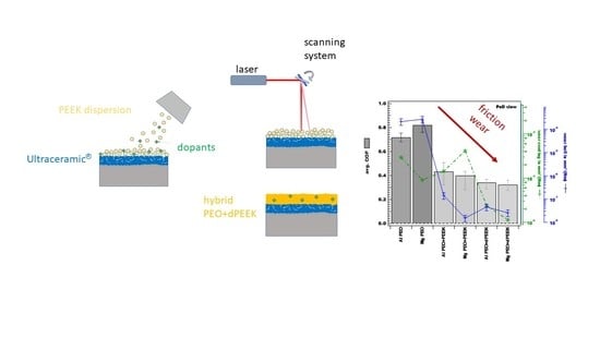
3.2.1. Wear of PEO Surfaces

The macroscopic pictures of the traces resulting after the sliding tests of the PEO surfaces are shown in Figure 4e,f. In the case of the pure PEO surface on both, the Al and Mg alloy, there appears to be a dark trace under both sliding conditions, which indicates an iron oxide layer as a result of abrasion from the 100Cr6 ball. In the case of the Mg PEO surface, the traces appear darker, indicating somewhat different wear behavior.
Figure 4a,b show the LSM recordings of the resulting traces and the corresponding ball appearance after the slow sliding tests, while Figure 4g,h represent the pictures of the fast sliding regime. The slow testing regime leads, on both, Al and Mg PEO surfaces, to a ridge-like boundary of the sliding trace containing the worn particles of the ball, which shows deep abrasive grooves. The wear of the ball increases with the load, whereas the coating shows somewhat more prominent marks in the fast sliding regime.
Figure 5 shows the summarized results of the Kn values and average COF (coefficient of friction) for all tested samples. It is obvious that the wear coefficient of the ball (blue line) is almost the same for both PEO surfaces under both testing conditions. The different alloys and testing regimes have more influence on the coating’s wear coefficient (green line): The PEO on Mg shows somewhat lower wear than the Al PEO under both testing conditions, while the fast testing condition leads to lowering wear on both substrate alloys.
By comparing the SEM and EDS results of the PEO surfaces after the slow testing regime in Figure 6, it becomes clear, that this condition leads to an increased oxide layer and broader areas of iron oxides on the Al PEO surface. Taking into account the roughness values (Figure 1a) and the morphology of the PEO coatings (Figure 2), one can conclude, that the smoother and softer surface of the Mg PEO leads to more even wear effects, while the harder and rougher Al PEO surface acts like a rasp on the ball. EDS results indicate, that after the sliding tests Al2O3-phases appear as higher islands, which are smoothed within the sliding process, and a thin iron oxide layer (around 1 µm) forms on the plateaus (see results in Figure 6). The wear tracks are mainly abrasive grinding tracks of the steel ball, as was observed by Qi et al. [14]. Interpreting the resulting roughness values after the sliding traces in Figure 1a, the roughness peaks of the coating decrease, while the value of the valley depth stays constant. In the case of Mg PEO, the slow sliding trace shows indentations and cracks within the coating being evidence of the weakness of the substrate, which buckles due to the load. While in the middle of the sliding trace there seems to be a lower amount of iron for the Mg PEO than for the Al PEO surface, the dead point shows huge iron containing flakes for Mg PEO, being evidence of high wear of the ball and a high static friction. Therefore, the coefficient of friction is higher under the slow testing regime for the Mg PEO surface and appears almost stable during the whole testing time, while the Al PEO coating shows a running-in with a low COF (compare Figure 4c,d). Thus, in that case the peaks of the coating are smoothening in the first 7 m; afterwards, the wear of the steel ball dominates. Similar effects were reported by Qi et al. [14], who supposed, that in a wear application, the microstructure like volcanoes peaks of Al2O3 first made contact with the grinding ball, and then peeled off under shear stress. The main failure mode of the coatings were abrasive wear and spalling failure for Al PEO.
Under the fast testing regime, Al PEO shows a high variation in the COF after the running-in phase (Figure 4i). The SEM and EDS analyses (shown in Figure 7a,b) indicate fine abrasive particles of iron and a fissured PEO surface. Therefore, it can be concluded, that there are rearranging processes during the whole testing time. Toulabifard et al. supposed the particles spalling from the surface and debris accumulation at the scar edge intensify the wear damage and lead to the increase in COF [17]. The dead point area exhibits a low amount of Fe flakes, which is in accordance with the lower COF at the dead points (Figure 4i). The wear of the ball is higher than that for the Mg PEO surface under the fast testing regime, whereas the Mg PEO sliding trace exhibits smeared oriented flakes of the iron oxide (Figure 7d,f). Due to the softer surface of MgO the adhesive effect dominates in this system, leading to a smoother development of the friction coefficient, which stabilizes after a running-in phase around 0.7. Furthermore, the wear of the Mg PEO surface is much lower, indicating almost no wear on the coating side. Therefore, it is evidence of the advantage of the low roughness and hardness of the Mg PEO surface, which leads to improved sliding behavior and a low wear rate, in contradiction to other studies [25,49], which report a failure of the PEO coating on Mg alloys at increased loads above 5 N. At the dead point broad Fe scalls can be found (Figure 7e), which might have formed during the running-in phase (Figure 4j), whereas the friction at the dead points is notably higher than in the stroke region. As indicated in Figure 7e,f, some cracks in the PEO surface are signs of the substrate weakness under 10 N normal force, since the thin PEO coating of around 10 µm does not provide enough influence volume for the high load.

3.2.2. Wear of Hybrid Surfaces

The tribological results of the PEO + PEEK hybrid coatings on both alloys after the two sliding test conditions are shown in Figure 8. Looking at the friction results, it becomes obvious, that in all cases the hybrid surfaces lead to a decrease in the friction in comparison to the naked PEO surface. Therefore, the PEEK top coating acts as a solid lubricant in this system. Especially, in the case of the slow sliding regime on the Al PEO + PEEK surface, the sliding curve exhibits smooth and stable behavior after a certain running-in distance. In the case of Mg PEO + PEEK there are some break-ins in the COF curve, indicating a slip-stick behavior in this tribological system under those testing parameters. This might be due to the higher number of pores in the Mg PEO + PEEK, as well as the deeper valleys in this coating (see Figure 1). Furthermore, the lower hardness of the PEEK top layer on the Mg alloy may lead to a higher adhesive wear behavior. In both cases (Al and Mg PEO + PEEK coatings) the dead points (Figure 9a,b) are governed by grooves, which are due to microcutting effects in the regions of highest wear. Additionally, adhered material can be found. At the middle of the trace, where the velocity t is on its highest, the grooves are less dominant. Here, viscous flow and material transfer might be the dominating wear mechanisms, as reported by Zhang and Schlarb for PEEK surfaces for a pressure of 4 MPa [50]. The trace of Al PEO + PEEK under the slow sliding regime exhibits a thin layer of Fe, as marked in Figure 9a. Furthermore, the amount of iron measured by EDS at the dead points is much higher than that for the Mg PEO + PEEK surface, which is in agreement with the determined lower wear coefficient for the ball (see values in Figure 4a). The middle of the trace of Mg PEO + PEEK does not exhibit any iron content but pulled-out PEEK fragments and ripple-like structures perpendicular to the sliding direction, which are also witnesses of the slip-stick effect [51].
Under both testing regimes the Mg PEO + PEEK coating leads to higher wear on the coating side than the corresponding coatings on the Al alloy, while in the fast testing regime the Mg PEO + PEEK coating exhibits a worn-through PEEK top layer, which is visible in Figure 9d and is the reason for the increased COF in that experiment at around 700 m sliding distance (see Figure 8j). Since the friction remains low after this, the PEEK still acts like a solid lubricant, stored in the cavities of the PEO surface, whereas the wear of the ball remains the same as for the intact Al PEO + PEEK coating (see Figure 5). Thus, the higher wear of the coating has no negative effect on the counter body. The dominating wear appearance of the neat PEEK hybrid coatings under the fast testing conditions is third-body-abrasion, which is due to the abrasive particles of the counter body ball acting in the tribo-contact and leading to grooves parallel to the sliding direction in the middle of the sliding trace (see Figure 9c,d). Both tested systems show a smoothening of the surface peeks accompanied by a filling of the valleys (see Figure 1a), so that a smooth PEEK surface results within the sliding tests. Since PEEK has a low resistance to plastic deformation [52], the surface shows typical grooves in the sliding direction in the middle of the sliding trace, accompanied by smearing effects and ploughing, which are typical for PEEK wear behavior [43,51].
The dead point of the fast sliding test on Al PEO + PEEK exhibits a thick layer of iron, while for the Mg PEO + PEEK surface besides iron debris, debris of the exhibited PEO surface can be found (Figure 9c,d). Due to the high pressure of 10 N and a zero velocity at the dead points, the counter body sinks in the PEEK top layer, while the adhesive forces are strong by the acceleration leading to high adhesive wear on the ball. This effect might be increased by the softer Mg PEO + PEEK surface. Furthermore, the PEO interface might have more influence on the sliding behavior, which is reflected in the friction force: The development exhibits some irregularities. The wear of the 100Cr6 ball appears as a circle-like grinded area, while the wear coefficient is unrepentant from the substrate material.
Thus, the PEEK top layers have thicknesses of 12–20 µm, they do not show a worn-through exempt Mg PEO + PEEK under the fast testing regime, as was reported for PEEK coatings on steel by Hou et al. [44], while the COF is comparable for the reported pure PEEK coating against steel [39,40,44,46,52]. The influence of the sliding speed and load on the coefficient of friction reported by Laux et al. [53] could not be found for the coatings, studied here, since the average friction is mostly stable under both testing regimes for the two substrate materials.
The positive influence of doping with additives of the dPEEK dispersion can be observed in Figure 10: Under the slow testing regime, the development of the friction is very stable and low for both substrate materials, the slip-stick behavior, which was found for the naked PEEK top layer, is repressed. The main wear effect is a formation of a desirable tribo-film on the 100Cr6 ball, whereas the wear of the coating is extremely low.
As can be seen in the SEM images of the worn surfaces in Figure 11, the slow sliding regime produced small amounts of Fe debris on the hybrid surfaces doped by additives. No Fe layer was formed, as it was the case for the pure PEEK top layers, shown in Figure 9. For the dPEEK top layers, small iron particles were surrounded by additive particles in the middle of the trace. On both substrate materials ripple-like structures perpendicular to the sliding direction were found, indicating an adhesive force leading to tangential deformation [52]. At the dead points some iron particles were found in such slipping depressions. The viscoelastic ploughing effect leads to material removal [43], which was observed for the native PEEK top layers as a main wear mechanism, but did not take place in the dPEEK top layers in the slow testing regime.
Figure 12 shows the cross-sections in the middle of the sliding traces. No iron was found on the surface for the slow testing regime of the Al PEO + dPEEK surface (see Figure 12a); the dPEEK coating thickness remained between 14–17 µm, also indicating the low wear of the coating, as determined in Figure 4. A crack in the porous outer layer of the Al PEO surface appeared, indicating high stress due to the low sliding velocity. In the case of Mg PEO + dPEEK the dPEEK thickness in the slow sliding trace remained still 14–16 µm, indicating almost no wear of the top layer under those testing parameters. The interface between PEEK and PEO did not show any peculiarities. The softer PEEK top layer and the lower roughness of the Mg PEO had a positive influence on the wear behavior in this system.
Under the fast testing regime an improvement in the friction behavior can also be observed for the dPEEK systems. The PEO + dPEEK on the Al substrate shows almost no slip-stick behavior, as it was the case for the native PEEK top layer (see Figure 10i). Here, the additives acted like imbedded load dumpers. The SEM observations indicated a thin iron layer in the middle of the trace (see Figure 11c), which was also visible in the cross section in Figure 12b. The iron particles were embedded in the dPEEK top layer, while the remaining thickness of the dPEEK was around 6.5–8 µm. For the doped hybrid surface on the Mg substrate no iron particles were detected in the cross section, the remaining dPEEK thickness was around 6–7 µm (Figure 12d); as it was the case for Mg PEO + PEEK system a wearing-through, did not occur here. The surface SEM observation showed an ultrafine distribution of additives and a very thin iron layer in the depressions at the dead points of the fast sliding trace (see Figure 11d). The middle of that trace exhibited a very low amount of iron, a coarser ripple-like structure and almost no grooves parallel to the sliding direction.
The resulting roughness values after the fast sliding regime on the Mg PEO + dPEEK surface showed an increase in the peak’s height, as shown in Figure 12a. This can be confirmed by the cross-sectional view in Figure 12d and is due to the adhesive behavior and the formation of the ripple-like structure mentioned before.
One can conclude that the particles reduce the coating deformation during the sliding tests and reduce the true contact area, as was suggested by Hou et al. [44] when incorporating inorganic fullerene-like nanoparticles in PEEK coatings, in contradiction to this publication, though, the higher hardness of the coating did not lead to a lower wear in our experiments.

4. Conclusions

In the present study, novel hybrid coatings for lightweight alloys with high wear resistance and by low friction were introduced and examined. Pure and dense PEO coatings on lightweight alloys represent a wear-resistant surface solution, but induce high abrasive wear on the counter body under different tribological testing regimes, accompanied by a high coefficient of friction. PEEK has been applied as a top coating on PEO surfaces in a novel laser-guided process, leading to hybrid surfaces, whereas PEEK acts as a solid lubricant, reducing friction and wear on the counter body side. The tribological effects of those hybrid surfaces were studied and interpreted by taking into account the mechanical, morphological and topographical issues of the surfaces.
The following conclusions can be drawn:
  • While the PEO surface acts as a hard and dense shell for the lightweight alloy, the hybrid solution in combination with doped PEEK coating leads to low friction and improved wear behavior.
  • Lower stiffness of the PEEK on the Mg alloy results in elastic deformation and, thus, a higher absorbance of impact energy, leading to most remarkable positive wear and friction influences on the hybrid surface of the Mg alloy.
  • After a wear down of the PEEK top coating the stored PEEK in the caverns of the PEO surface is still acting as a solid lubricant keeping the coefficient of friction low.
  • The doped PEEK hybrid coating leads to an improved wear behavior of the surface, whereas the additives act like dumpers.
  • By introducing additives into the PEEK dispersion, the wear mechanism is changed from ploughing and third-body abrasion to adhesive deformation and transfer film forming accompanied by almost no wear of both, coating and counter body side.
  • The wear on the counter body side can be reduced by three orders of magnitude by the doped hybrid surface solutions.
  • Thus, doped hybrid coatings are attractive solutions for aggressive sliding conditions.
Therefore, the applicability of lightweight alloys can be increased by such hybrid surfaces.

Author Contributions

Conceptualization, A.B. and J.Z.; methodology, A.B. and J.Z.; formal analysis, A.B.; investigation, A.B.; writing—original draft preparation, A.B.; writing—review and editing, A.B. and J.Z.; visualization, A.B. All authors have read and agreed to the published version of the manuscript.

Funding

This research was partially funded by the German Federal Ministry of Education and Research (BMBF) within the framework of the funding measure ‘KMU-innovativ–Klima-Ressourcen-und Energieeffizienz’ (grant number: 01LY1601A-C).

Conflicts of Interest

The authors declare no conflict of interest.

References

  1. Cole, G.S.; Sherman, A.M. Light weight materials for automotive applications. Mater. Charact. 1995, 35, 3–9. [Google Scholar] [CrossRef]
  2. Singh, I.B.; Singh, M.; Das, S. A comparative corrosion behavior of Mg, AZ31 and AZ91 alloys in 3.5% NaCl solution. J. Magnes. Alloys 2015, 3, 142–148. [Google Scholar] [CrossRef] [Green Version]
  3. Hirsch, J.; Al-Samman, T. Superior light metals by texture engineering: Optimized aluminum and magnesium alloys for automotive applications. Acta Mater. 2013, 61, 818–843. [Google Scholar] [CrossRef]
  4. Graf, M.; Härtel, S.; Awiszus, B. Application of numerical simulation for lightweight design. J. Mech. Eng. 2019, 8, 176–191. [Google Scholar]
  5. Tisza, M.; Czinege, I. Comparative study of the application of steels and aluminium in lightweight production of automotive parts. Int. J. Lightweight Mater. Manuf. 2018, 1, 229–238. [Google Scholar] [CrossRef]
  6. Joost, W.J. Reducing Vehicle Weight and Improving U.S. Energy Efficiency Using Integrated Computational Materials Engineering. JOM 2012, 64, 1032–1038. [Google Scholar] [CrossRef] [Green Version]
  7. Aghion, E.; Bronfin, B.; Eliezer, D. The role of the magnesium industry in protecting the environment. J. Mater. Process. Technol. 2001, 117, 381–385. [Google Scholar] [CrossRef]
  8. Bland, L.G.; Scully, L.C.; Scully, J.R. Assessing the Corrosion of Multi-Phase Mg-Al Alloys with High Al Content by Electrochemical Impedance, Mass Loss, Hydrogen Collection, and Inductively Coupled Plasma Optical Emission Spectrometry Solution Analysis. Corrosion 2017, 73, 526–543. [Google Scholar] [CrossRef]
  9. Joost, W.J. Targeting High Impact R&D for Automotive Magnesium Alloys. In Magnesium Technology 2017; Solanki, K.N., Orlov, D., Singh, A., Neelameggham, N.R., Eds.; Springer International Publishing: Cham, Switzerland, 2017; pp. 5–6. [Google Scholar]
  10. Guo, K.W. A Review of Magnesium/Magnesium Alloys Corrosion and its Protection. Recent Pat. Corros. Sci. 2010, 2, 13–21. [Google Scholar] [CrossRef] [Green Version]
  11. Luo, A.A. Magnesium Development as a Lightweight Material—In Competition with Other Structural Materials. In Magnesium Technology 2017; Solanki, K.N., Orlov, D., Singh, A., Neelameggham, N.R., Eds.; Springer International Publishing: Cham, Switzerland, 2017; p. 7. [Google Scholar]
  12. Algahtani, A.; Mahmoud, E.R.I.; Khan, S.; Tirth, V. Experimental Studies on Corrosion Behavior of Ceramic Surface Coating using Different Deposition Techniques on 6082-T6 Aluminum Alloy. Processes 2018, 6, 240. [Google Scholar] [CrossRef] [Green Version]
  13. Arrabal, R.; Mohedano, M.; Matykina, E.; Pardo, A.; Mingo, B.; Merino, M.C. Characterization and wear behaviour of PEO coatings on 6082-T6 aluminium alloy with incorporated α-Al2O3 particles. Surf. Coat. Technol. 2015, 269, 64–73. [Google Scholar] [CrossRef]
  14. Qi, X.; Shang, H.; Ma, B.; Zhang, R.; Guo, L.; Su, B. Microstructure and Wear Properties of Micro Arc Oxidation Ceramic Coatings. Materials 2020, 13, 970. [Google Scholar] [CrossRef] [Green Version]
  15. Matykina, E.; Arrabal, R.; Mohedano, M.; Mingo, B.; Gonzalez, J.; Pardo, A.; Merino, M.C. Recent advances in energy efficient PEO processing of aluminium alloys. Trans. Nonferr. Met. Soc. China 2017, 27, 1439–1454. [Google Scholar] [CrossRef]
  16. Tian, J.; Luo, Z.; Qi, S.; Sun, X. Structure and antiwear behavior of micro-arc oxidized coatings on aluminum alloy. Surf. Coat. Technol. 2002, 154, 1–7. [Google Scholar] [CrossRef]
  17. Toulabifard, A.; Hakimizad, A.; Di Franco, F.; Raeissi, K.; Santamaria, M. Synergistic effect of W incorporation and pulsed current mode on wear and tribocorrosion resistance of coatings grown by plasma electrolytic oxidation on 7075 Al alloy. Mater. Res. Express 2019, 6, 106502. [Google Scholar] [CrossRef]
  18. Nasiri Vatan, H. Wear and Corrosion Performance of PEO-synthesized SiC Nanocomposite Coatings: Effect of Processing Time and Current Density. Int. J. Electrochem. Sci. 2016, 5631–5654. [Google Scholar] [CrossRef]
  19. White, L.; Koo, Y.; Neralla, S.; Sankar, J.; Yun, Y. Enhanced mechanical properties and increased corrosion resistance of a biodegradable magnesium alloy by plasma electrolytic oxidation (PEO). Mater. Sci. Eng. B Solid State Mater. Adv. Technol. 2016, 208, 39–46. [Google Scholar] [CrossRef] [PubMed] [Green Version]
  20. Guo, J.; Wang, L.; Wang, S.C.; Liang, J.; Xue, Q.; Yan, F. Preparation and performance of a novel multifunctional plasma electrolytic oxidation composite coating formed on magnesium alloy. J. Mater. Sci. 2009, 44, 1998–2006. [Google Scholar] [CrossRef]
  21. Bala Srinivasan, P.; Blawert, C.; Dietzel, W. Dry sliding wear behaviour of plasma electrolytic oxidation coated AZ91 cast magnesium alloy. Wear 2009, 266, 1241–1247. [Google Scholar] [CrossRef] [Green Version]
  22. Barati Darband, G.; Aliofkhazraei, M.; Hamghalam, P.; Valizade, N. Plasma electrolytic oxidation of magnesium and its alloys: Mechanism, properties and applications. J. Magnes. Alloys 2017, 5, 74–132. [Google Scholar] [CrossRef]
  23. Famiyeh, L.; Huang, X. Plasma Electrolytic Oxidation Coatings on Aluminum Alloys: Microstructures, Properties, and Applications. Mod. Concepts Mater. Sci. 2019, 2. [Google Scholar]
  24. Egorkin, V.S.; Gnedenkov, S.V.; Sinebryukhov, S.L.; Vyaliy, I.E.; Gnedenkov, A.S.; Chizhikov, R.G. Increasing thickness and protective properties of PEO-coatings on aluminum alloy. Surf. Coat. Technol. 2018, 334, 29–42. [Google Scholar] [CrossRef]
  25. Curran, J.A.; Kalkancı, H.; Magurova, Y.; Clyne, T.W. Mullite-rich plasma electrolytic oxide coatings for thermal barrier applications. Surf. Coat. Technol. 2017, 201, 8683–8687. [Google Scholar] [CrossRef]
  26. Wang, Z.; Wu, L.; Qi, Y.; Cai, W.; Jiang, Z. Self-lubricating Al2O3/PTFE composite coating formation on surface of aluminium alloy. Surf. Coat. Technol. 2010, 204, 3315–3318. [Google Scholar] [CrossRef]
  27. Wang, Y.M.; Jiang, B.L.; Lei, T.Q.; Guo, L.X. Microarc oxidation and spraying graphite duplex coating formed on titanium alloy for antifriction purpose. Appl. Surf. Sci. 2005, 246, 214–221. [Google Scholar] [CrossRef]
  28. Srinivasan, P.B.; Scharnagl, N.; Blawert, C.; Dietzel, W. Enhanced corrosion protection of AZ31 magnesium alloy by duplex plasma electrolytic oxidation and polymer coatings. Surf. Eng. 2010, 26, 354–360. [Google Scholar] [CrossRef] [Green Version]
  29. Liang, J.; Wang, P.; Hu, L.; Hao, J. Tribological properties of duplex MAO/DLC coatings on magnesium alloy using combined microarc oxidation and filtered cathodic arc deposition. Mater. Sci. Eng. A 2007, 454–455, 164–169. [Google Scholar] [CrossRef]
  30. Liu, Y.-F.; Liskiewicz, T.; Yerokhin, A.; Korenyi-Both, A.; Zabinski, J.; Lin, M.; Matthews, A.; Voevodin, A.A. Fretting wear behavior of duplex PEO/chameleon coating on Al alloy. Surf. Coat. Technol. 2018, 352, 238–246. [Google Scholar] [CrossRef] [Green Version]
  31. Awad, S.H.; Qian, H.C. Deposition of duplex Al2O3/TiN coatings on aluminum alloys for tribological applications using a combined microplasma oxidation (MPO) and arc ion plating (AIP). Wear 2006, 260, 215–222. [Google Scholar] [CrossRef]
  32. Seung, M.Y. Tribology of polymeric coatings for aggressive bearing applications. Diss. Urbana Ill. 2013. [Google Scholar]
  33. McCook, N.L.; Burris, D.L.; Bourne, G.R.; Steffens, J.; Hanrahan, J.R.; Sawyer, W.G. Wear resistant solid lubricant coating made from PTFE and epoxy. Tribol. Lett. 2005, 18, 119–124. [Google Scholar] [CrossRef]
  34. Martini, C.; Ceschini, L.; Tarterini, F.; Paillard, J.M.; Curran, J.A. PEO layers obtained from mixed aluminate–phosphate baths on Ti–6Al–4V: Dry sliding behaviour and influence of a PTFE topcoat. Wear 2010, 269, 747–756. [Google Scholar] [CrossRef]
  35. Chen, Y.; Lu, X.; Blawert, C.; Zheludkevich, M.L.; Zhang, T.; Wang, F. Formation of self-lubricating PEO coating via in-situ incorporation of PTFE particles. Surf. Coat. Technol. 2008, 337, 379–388. [Google Scholar] [CrossRef]
  36. Vaganov-Vil’kins, A.A.; Rudnev, V.S.; Pavlov, A.D.; Sukhoverkhov, S.V.; Kostin, V.I.; Lukiyanchuk, I.V. IR and Py-GC/MS investigation of composite PTFE/PEO coatings on aluminum. Mater. Chem. Phys. 2019, 221, 436–446. [Google Scholar] [CrossRef]
  37. Nunez, E.E.; Yeo, S.M.; Polycarpou, A.A. (Eds.) Purdue University, Tribological Behavior of PTFE, PEEK, and Fluorocarbon-Based Polymeric Coatings Used in Air-Conditioning and Refrigeration Compressors. In Proceedings of the 2010 International Compressor Engineering Conference, West Lafayette, IN, USA, 12–15 July 2010. [Google Scholar]
  38. Bhanavase, V.L.; Jogi, B.F. (Eds.) Parametric Study of Friction and Wear for Polyether Ether Ketone (Peek) Compoosite under Dry Sliding Condition. In Proceedings of the International Conference on Ideas, Impact and Innovation in Mechanical Engineering (ICIIIME 2017), Pune, India, 1–2 June 2017. [Google Scholar]
  39. Lin, L.; Pei, X.-Q.; Bennewitz, R.; Schlarb, A.K. Tribological Response of PEEK to Temperature Induced by Frictional and External Heating. Tribol. Lett. 2019. [Google Scholar] [CrossRef]
  40. Pei, X.-Q.; Lin, L.-Y.; Schlarb, A.K.; Bennewitz, R. Novel Experiments Reveal Scratching and Transfer Film Mechanisms in the Sliding of the PEEK/Steel Tribosystem. Tribol. Lett. 2016, 63, 492. [Google Scholar] [CrossRef]
  41. Burris, D.L.; Sawyer, W.G. Tribological behavior of PEEK components with compositionally graded PEEK/PTFE surfaces. Wear 2007, 262, 220–224. [Google Scholar] [CrossRef]
  42. Lu, Z.P.; Friedrich, K. On sliding friction and wear of PEEK and its composites. Wear 1995, 181–183, 624–631. [Google Scholar] [CrossRef]
  43. Hanchi, J.; Eiss, N.S. Dry sliding friction and wear of short carbon-fiber-reinforced polyetheretherketone (PEEK) at elevated temperatures. Wear 1997, 203–204, 380–386. [Google Scholar] [CrossRef]
  44. Hou, X.; Shan, C.X.; Choy, K.-L. Microstructures and tribological properties of PEEK-based nanocomposite coatings incorporating inorganic fullerene-like nanoparticles. Surf. Coat. Technol. 2008, 202, 2287–2291. [Google Scholar] [CrossRef]
  45. Rodriguez, V.; Sukumaran, J.; Schlarb, A.K.; de Baets, P. Influence of solid lubricants on tribological properties of polyetheretherketone (PEEK). Tribol. Int. 2016, 103, 45–57. [Google Scholar] [CrossRef]
  46. Buling, A.; Zerrer, J. Increasing the application fields of magnesium by ultraceramic®: Corrosion and wear protection by plasma electrolytical oxidation (PEO) of Mg alloys. Surf. Coat. Technol. 2019, 369, 142–155. [Google Scholar] [CrossRef]
  47. ELB (Eloxalwerk Ludwigsburg Helmut Zerrer GmbH 71642 Ludwigsburg-Neckarweihingen (DE)). Beschichtungsdispersion; herstellungsverfahren einer beschichtungsdispersion. EP 3 508 283 A3, 12 November 2018. [Google Scholar]
  48. Sändker, H.J.; Stollenwerk, J.; Zerrer, A. vorrichtung zum beschichten eines werkstücks mit mindestens einem hochleistungspolymer; beschichtungsverfahren. EP 3 498 383 A3, 29 October 2018. [Google Scholar]
  49. Sändker, H.; Stollenwerk, J.; Loosen, P. Laser-based process for polymeric tribological coatings on lightweight components. Surf. Coat. Technol. 2017, 332, 391–398. [Google Scholar] [CrossRef]
  50. Laux, K.A.; Jean-Fulcrand, A.; Sue, H.J.; Bremner, T.; Wong, J.S.S. The influence of surface properties on sliding contact temperature and friction for polyetheretherketone (PEEK). Polymer 2016, 103, 397–404. [Google Scholar] [CrossRef] [Green Version]
  51. Srinivasan, P.B.; Blawert, C.; Störmer, M.; Dietzel, W. Characterisation of tribological and corrosion behaviour of plasma electrolytic oxidation coated AM50 magnesium alloy. Surf. Eng. 2010, 26, 340–346. [Google Scholar] [CrossRef]
  52. Zhang, G.; Schlarb, A.K. Correlation of the tribological behaviors with the mechanical properties of poly-ether-ether-ketones (PEEKs) with different molecular weights and their fiber filled composites. Wear 2009, 266, 337–344. [Google Scholar] [CrossRef]
  53. Schroeder, R.; Torres, F.W.; Binder, C.; Klein, A.N.; de Mello, J.D.B. Failure mode in sliding wear of PEEK based composites. Wear 2013, 301, 717–726. [Google Scholar] [CrossRef]
Figure 1. (a) Roughness values for all observed surfaces before and after the sliding tests; (b) porosity of the hybrid coatings, (c) coating thicknesses of all systems with the hardness values for the corresponding top layers.
Lubricants 08 00065 g001
Figure 2. SEM, 3D and energy dispersive spectroscopy (EDS) results of the plasma electrolytical oxidation (PEO) surfaces on (a) Al 6082 and (b) Mg AZ31.
Lubricants 08 00065 g002
Figure 3. Morphology of the hybrid coatings: (ac) Al PEO + PEEK; (df) Al PEO + dPEEK; (gi) Mg PEO + PEEK; (jl) Mg PEO + dPEEK; left: 3D overview of the surfaces; middle: SEM zoomed in on the surfaces; right: cross-sectional view.
Lubricants 08 00065 g003
Figure 4. Wear and friction results of the PEO surfaces: (a,b) show the wear trace and the corresponding ball surfaces of Al and Mg PEO surfaces after the slow testing regime, respectively. (c,d) show the corresponding coefficient of friction of the slow regime in the upper part. The lower part shows selected positions within that curve. (e,f) show the macroscopic view of the sliding traces on the samples. (g,h) show the wear trace and the corresponding ball surfaces of Al and Mg PEO surfaces after the fast testing regime, respectively. (i,j) show the corresponding coefficient of friction of the slow regime in the upper part. The lower part shows selected positions within that curve.
Lubricants 08 00065 g004
Figure 5. Summarized results of the sliding test in terms of coefficients of friction (bars) and wear coefficients of the coating (green) and the ball (blue): (a) slow testing regime, (b) fast testing regime.
Lubricants 08 00065 g005
Figure 6. PEO surfaces after the slow sliding test regime: (a) SEM, 3D and EDS phase analysis of Al PEO surface; dead point of Al PEO surface; cross section of Al PEO in the middle of the sliding trace (b) SEM, 3D and EDS phase analysis of Mg PEO surface; dead point of Mg PEO surface; cross section of Mg PEO in the middle of the sliding trace.
Lubricants 08 00065 g006
Figure 7. SEM results for the ‘fast’ tested PEO surfaces: (a,b) Al PEO trace and dead point, (c) cross section of Al PEO with EDS distribution of Fe; (d,e) Mg PEO trace and dead point; (f) cross section of Mg PEO with EDS distribution of Fe.
Lubricants 08 00065 g007
Figure 8. Wear and friction results of the hybrid PEO + PEEK surfaces: (a,b) the wear trace and the corresponding ball surfaces of Al and Mg PEO + PEEK surfaces after the slow testing regime, respectively; (c,d) the corresponding coefficient of friction of the slow regime in the upper part. The lower part shows selected positions within that curve; (e,f) the macroscopic view of the sliding traces on the samples; (g,h) the wear trace and the corresponding ball surfaces of Al and Mg PEO + PEEK surfaces after the fast testing regime, respectively; (i,j) the corresponding coefficient of friction of the slow regime in the upper part. The lower part shows selected positions within that curve.
Lubricants 08 00065 g008
Figure 9. SEM observations of the resulting worn hybrid PEO + PEEK surfaces: (a) Al PEO+PEEK surface after the slow sliding regime, trace and dead point; (b) Mg PEO+PEEK surface after the slow sliding regime, trace and dead point; (c) Al PEO+PEEK surface after the fast sliding regime, trace and dead point; (d) Mg PEO+PEEK surface after the fast sliding regime, trace and dead point.
Lubricants 08 00065 g009
Figure 10. Wear and friction results of the hybrid PEO + dPEEK surfaces: (a,b) the wear trace and the corresponding ball surfaces of Al and Mg PEO + dPEEK surfaces after the slow testing regime, respectively; (c,d) the corresponding coefficient of friction of the slow regime in the upper part. The lower part shows selected positions within that curve; (e,f) the macroscopic view of the sliding traces on the samples; (g,h) the wear trace and the corresponding ball surfaces of Al and Mg PEO + dPEEK surfaces after the fast testing regime, respectively; (i,j) the corresponding coefficient of friction of the slow regime in the upper part. The lower part shows selected positions within that curve.
Lubricants 08 00065 g010
Figure 11. SEM observations of the resulting worn PEO + dPEEK hybrid surfaces doped by additives: (a) Al PEO+dPEEK surface after the slow sliding regime, trace and dead point; (b) Mg PEO+dPEEK surface after the slow sliding regime, trace and dead point; (c) Al PEO+dPEEK surface after the fast sliding regime, trace and dead point; (d) Mg PEO+dPEEK surface after the fast sliding regime, trace and dead point.
Lubricants 08 00065 g011
Figure 12. Cross-sections of the doped hybrid surfaces after the sliding tests: (a) Al PEO + dPEEK after slow testing regime; (b) Al PEO + dPEEK after fast testing regime; (c) Mg PEO + dPEEK after slow testing regime; (d) Mg PEO + dPEEK after fast testing regime.
Lubricants 08 00065 g012
Table 1. Chemical composition of the substrate materials.
Element in wt%AlMgSiFeCuMnZnTi
Al AW6082balance0.6–1.20.7–1.30.50.10.4–1.00.20.1
Mg AZ312.5–3.5balance0–0.1-0–0.50.2–1.00.6–1.4-
Table 2. Testing parameters for the pin-on-disc modes ‘slow’ and ‘fast’.
ParametersSlowFast
f/Hz0.61.4
vmax/cm/s0.6429.7
FN/N410
path length/mm340
l total distance/m801000

