Article

Tribocorrosion Behaviour of Ti6Al4V Produced by Selective Laser Melting for Dental Implants

by
Luís M. Vilhena
*,
Ahmad Shumayal
,
Amílcar Ramalho
and
José António Martins Ferreira
CEMMPRE, Centre for Mechanical Engineering, Materials and Processes, University of Coimbra, Rua Luís Reis Santos, 3030-788 Coimbra, Portugal
*
Author to whom correspondence should be addressed.
Lubricants 2020, 8(2), 22; https://doi.org/10.3390/lubricants8020022
Submission received: 17 December 2019 / Revised: 11 February 2020 / Accepted: 18 February 2020 / Published: 21 February 2020
(This article belongs to the Special Issue Tribology of Biomaterials)

Abstract

:
Additively produced Ti6Al4V implants display mechanical properties that are economically infeasible to achieve with conventional subtractive methods. The aim of the present research work was to characterize the tribocorrosion behaviour of the newly produced Ti6Al4V, also known as titanium grade 5, by a selective laser melting (SLM) technique and compare it with another specimen produced by a conventional method. It was found that the tribological properties were of the same order, with the wear rate being k= 6.3 × 10⁻⁴ mm3/N·m and k = 8.3 × 10⁻⁴ mm3/N·m for respectively, SLM and conventional method. Regarding the friction behaviour, both methods exhibited similar COF in the order of 0.41–0.51. However, electrochemically, the potentiodynamic polarization curves presented some differences mainly in the potential range of the passive films and passive current density formed, with the passive current density being lower for the SLM method.

Graphical Abstract

1. Introduction

The most widely used materials for the manufacture of dental implant fixtures are commercially pure titanium, Ti grade 2 or grade 4 [1,2,3,4]. However, Ti grade 5 (Ti6Al4V) is the most commonly used to produce abutment and prosthetic structures due to its excellent mechanical properties, biocompatibility and suitable tribocorrosion behaviour. The addition of 6% Al allows higher mechanical strength and the presence of 4% V stabilizes the (α + β) phase by maintaining the corrosion resistance of the titanium alloy [1,5].
Ti6Al4V pieces have a passive film that is formed on their surface in the presence of oxygen. This passive protective layer of about 3–10 nm in depth is composed of TiO2 and acts as a physical barrier between the bulk material and the environment. During the mastication process, loads of the order of hundreds of Newtons are frequently applied to dental implants and consequently, they are exposed to degradation mechanisms that are a combination of wear and corrosion, particularly on surface regions that are subject to a relative contact movement under the presence of human fluids that are considerably aggressive (e.g., chloride ions, Cl). Figure 1 presents a schematic picture showing the synergism between wear and corrosion. When the passive film formed in the presence of oxygen on the surface of the Ti6Al4V is destroyed and removed (depassivation) due to the mechanical loading, fresh material is exposed to the electrolyte where corrosion reaction take place (wear-accelerated corrosion) [6]. The wear rate for the synergism created is higher than the sum of each individual action [7,8,9,10,11,12,13,14].
Additive manufacturing (AM) methods are processes that fuse materials layer by layer, to produce items based on 3D model data [16] and allows rapid prototyping and direct fabrication of metallic implants. A particular example of the above mentioned AM methods is selective laser melting (SLM) that is considered the most popular and commercially-available powder bed fusion AM method [16]. In SLM, metallic powders are uniformly spread on the building platform by a rake. A focused laser beam, usually CO2 (10.6-µm wavelength) or Nd:YAG (1.06-µm wavelength) scans the surface according to the prescribed path and selectively melts the powders in this layer, after which a new layer of powders is spread after lowering the building platform to the distance of the layer thickness (in the scale of tens of microns) [16,17].
According to Dai et al. [18], the SLM method has been increasingly used to produce Ti6Al4V and other Ti alloys [19,20,21,22,23,24,25], such as Ti-24Nb-4Zr-8Sn, Ti-5Cu and Ti-TiB, due to the capability that SLM has to produce alloys with comparable or even better mechanical properties than those produced by conventional techniques. Related with the microstructure in conventional produced Ti6Al4V, a duplex structure exists as a mixture of α phase (hcp) and β phase (bcc). This microstructure can be modified with various heat treatments [26]. However, the microstructure of SLM produced samples shows acicular α’ martensitic with some prior β grains as shown in Figure 2. This difference in the microstructure could justify different mechanical properties and consequently different tribological behaviour.
The aim of the present research work is to understand the tribocorrosion behaviour of the pair Ti6Al4V/ZrO2 under reciprocating sliding conditions lubricated with artificial saliva for Ti6Al4V obtained by selective laser melting and by a conventional method. To accomplish this, potentiodynamic polarization curves and open circuit potential (OCP) technique were performed.

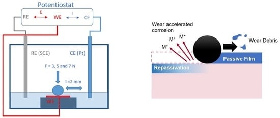
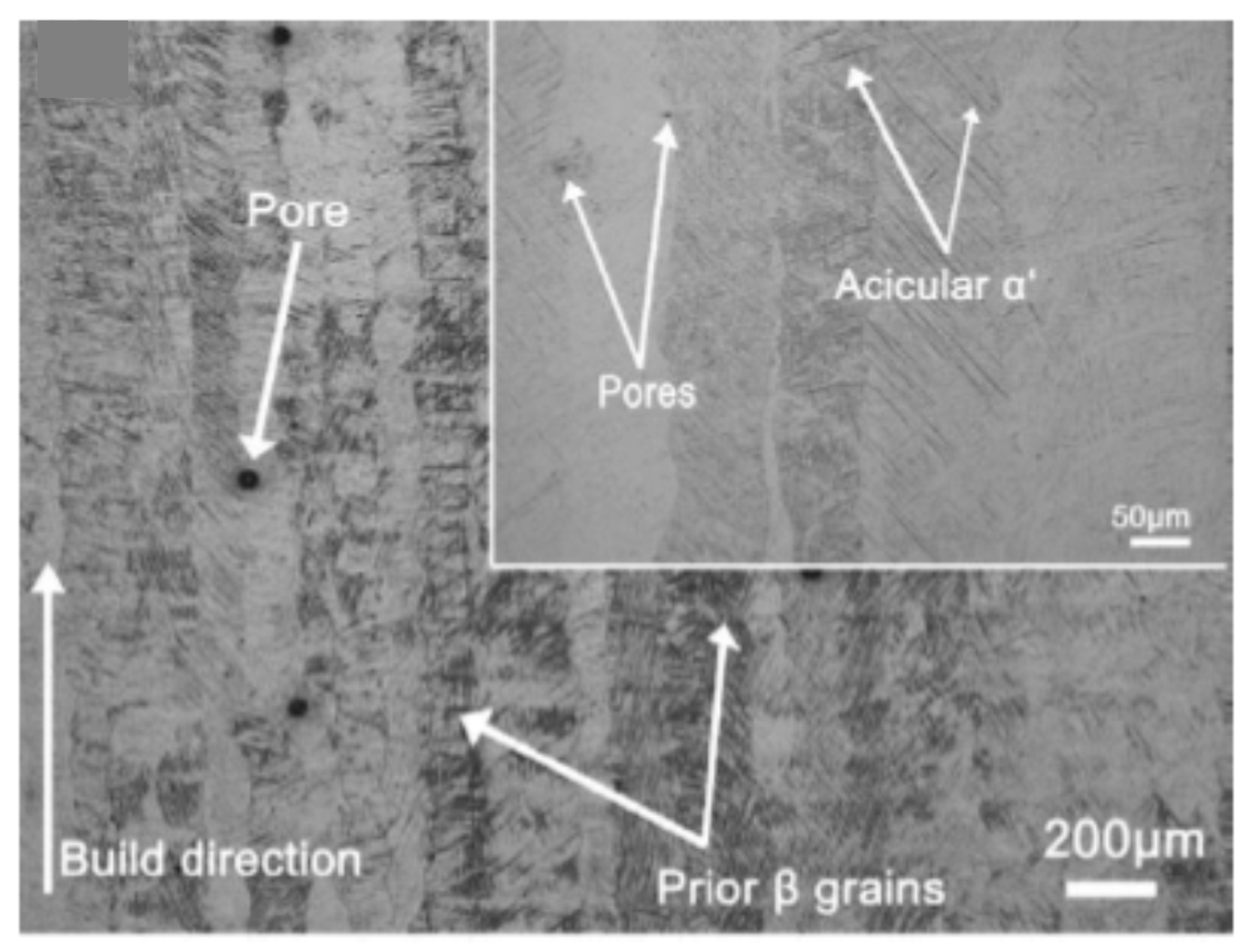
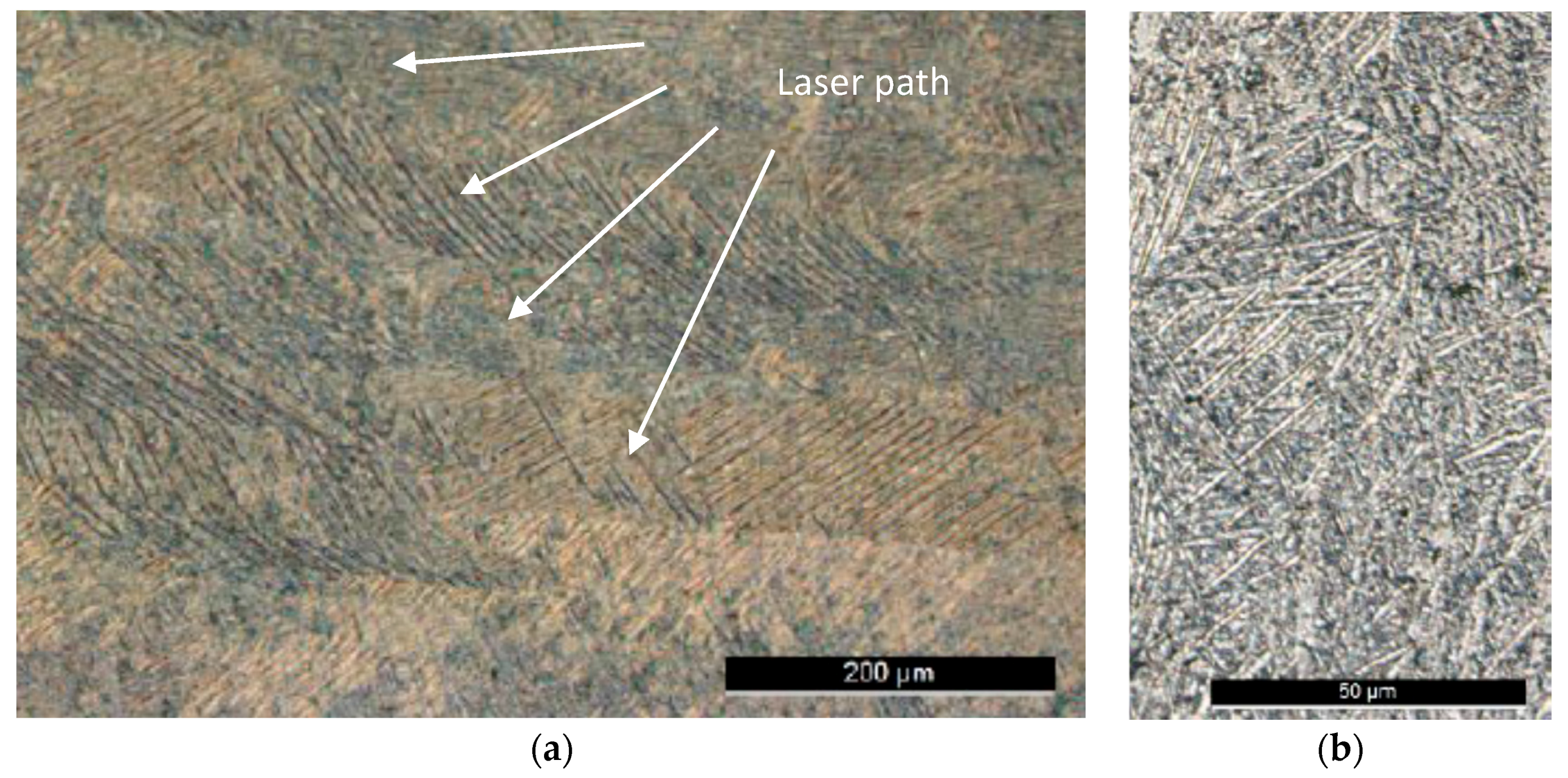
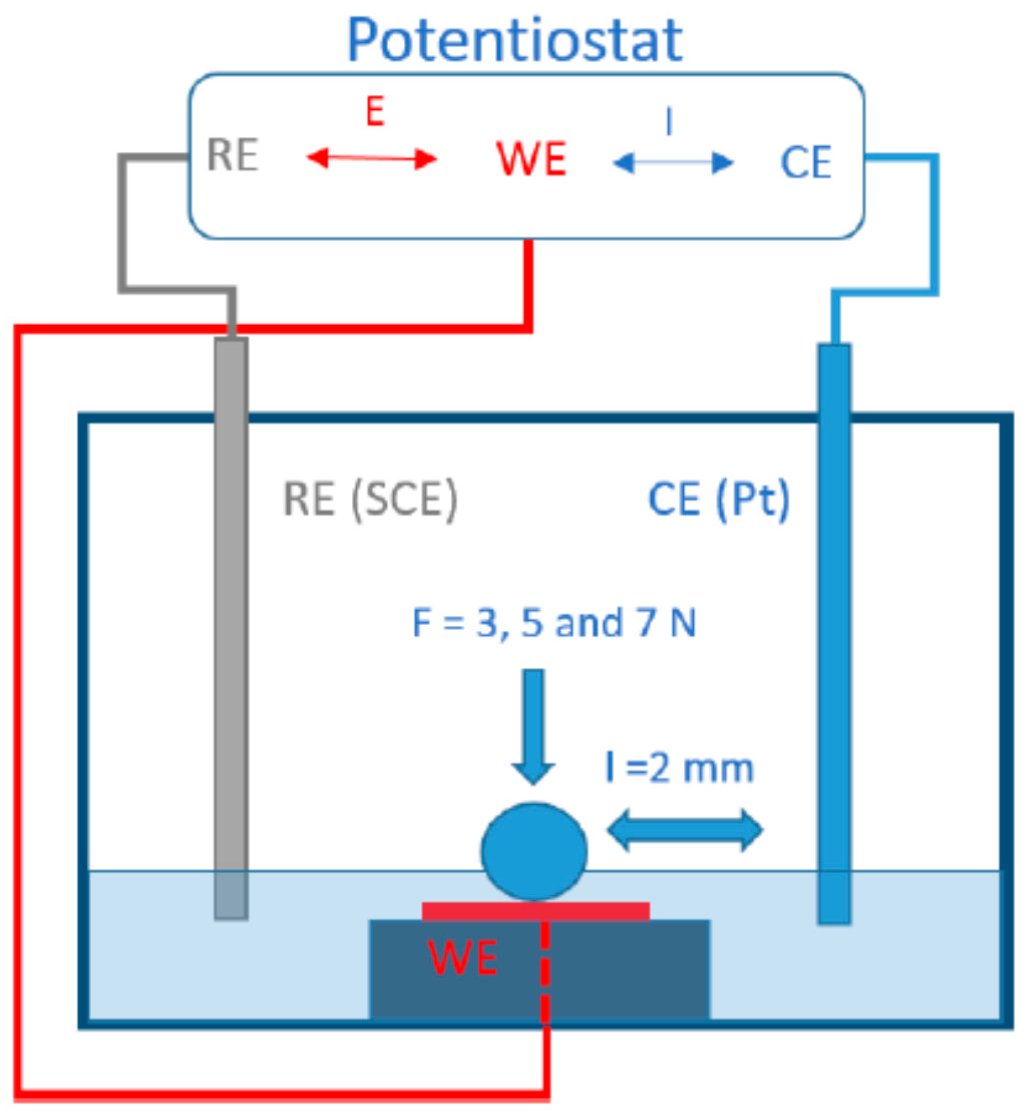
2. Materials and Methods

Two specimens of titanium grade 5 (Ti6Al4V) were prepared. One produced by the traditional/conventional powder metallurgy process that consists in the following steps: mixing, compaction and sintering; and the other obtained from SLM method with the chemical composition and mechanical properties shown in Table 1 and Table 2, respectively.
The specimen produced by additive manufacturing was obtained using laser powder-bed fusion technology, with the different successive layers (XY-plane) growing towards the Z direction (Z-axis)—direction of the loading application. The samples were formed using a ProX DMP 320 high-performance metal additive manufacturing system (3D systems), incorporating a 500 W fiber laser. Layers of 30 mm thickness were used to produce the samples using Ti6Al4V alloy powder with an average particle size of 40 µm.
Both specimens were polished using SiC abrasive papers to an average surface roughness of approximately 0.1 µm. The roughness measurements were performed using a Mitutoyo Surftest—500 profilometer (Mitutoyo, IL, USA) in accordance with ISO standard 4287.
Figure 3 shows the microstructure of Ti6Al4V produced by SLM where it is possible to see the laser path (Figure 3a). The black zones correspond to the α-phase while the white zones correspond to the vanadium-rich β-phase. The microstructure, with grains of acicular geometry, has prevalence of α blades surrounded by small percentages of β blades. The grain geometry is mainly due to the high cooling rate that characterizes the SLM processes.
As shown in the schematic arrangement represented in Figure 4, the three-electrode setup was composed by a saturated calomel electrode (SCE) that works as reference electrode (RE) with a constant potential (242.2 mV vs. Standard Hydrogen Electrode (SHE)) which is the model Radiometer XR110 (Hach, Düsseldorf, Germany). It consists of a glass body, saturated calomel reference system, refillable electrolyte (sat. KCl), ground joint, and porous pin junction. This electrode was coupled with a platinum sheet counter electrode (CE), model XM120. A polycarbonate container holds the specimen to study, considered as working electrode (WE), keeping it submerged in the electrolyte (artificial saliva). An insulated wire was soldered to our cut samples. Then the cold-cure epoxy resin mixture was poured with a suitable amount of filler to hold the samples securely in their plastic casings while simultaneously shielding the soldered wire from the environment. An O-ring rubber seal at the bottom ensures that the bottom of the sample remains dry and the hole beneath makes it possible for the wire to exit the container and connected to the potentiostat. The potentiostat used was a Bio-Logic Science Instrument SP-50 (Hach, Düsseldorf, Germany) which was connected to a computer and controlled by EC lab version 11.26 (December, 2018).
The reciprocating sliding tests were performed with a varying load of 3, 5 and 7 N. The frequency was fixed to 3 Hz and the stroke 2 mm, corresponding to 0.012 m/s of linear sliding speed. During the test setup, the specimens were immersed with artificial saliva with the composition shown in Table 3. The artificial saliva was replaced after every single test. Contact was then made between the 10 mm diameter ZrO2 ball and the specimen and then the load was applied corresponding to contact pressures between 0.42 and 0.57 GPa according to Hertzian contact theory and rubbing was initiated. The sintered ZrO2 ball presented a density of 6.05 g/cm3 and a microhardness of approximately, 1250 Kgf/mm2 (HV). Open CIRCUIT POTENTIAL measurements were taken for 3600 s before rubbing experiment. The sliding distance was set to 15 m corresponding to a rubbing time of 1250 s. After sliding, the potential was monitored for 3600 s until reach the equilibrium. The sequential test procedures are summarized in Table 4. Potentiodynamic polarization curves were recorded between −1.2 V and +1.2 V vs. SCE at a scan rate of 1 mV/s as shown in Table 5.
In the projected tribometer, the upper specimen is connected to an eccentric and rod mechanism, which generates the reciprocating harmonic motion with 2 mm of stroke. A spindle-spring mechanism is used to apply the normal load, assessed by a load-cell. An acrylic tub, supported by a set of plane springs, was used to build the tribocorrosion cell. A force sensor restricts the tangential motion of the acrylic tub allowing the assessment of the friction force. Labview is used to control the rig and to acquire the data over the test duration.

3. Results and Discussion

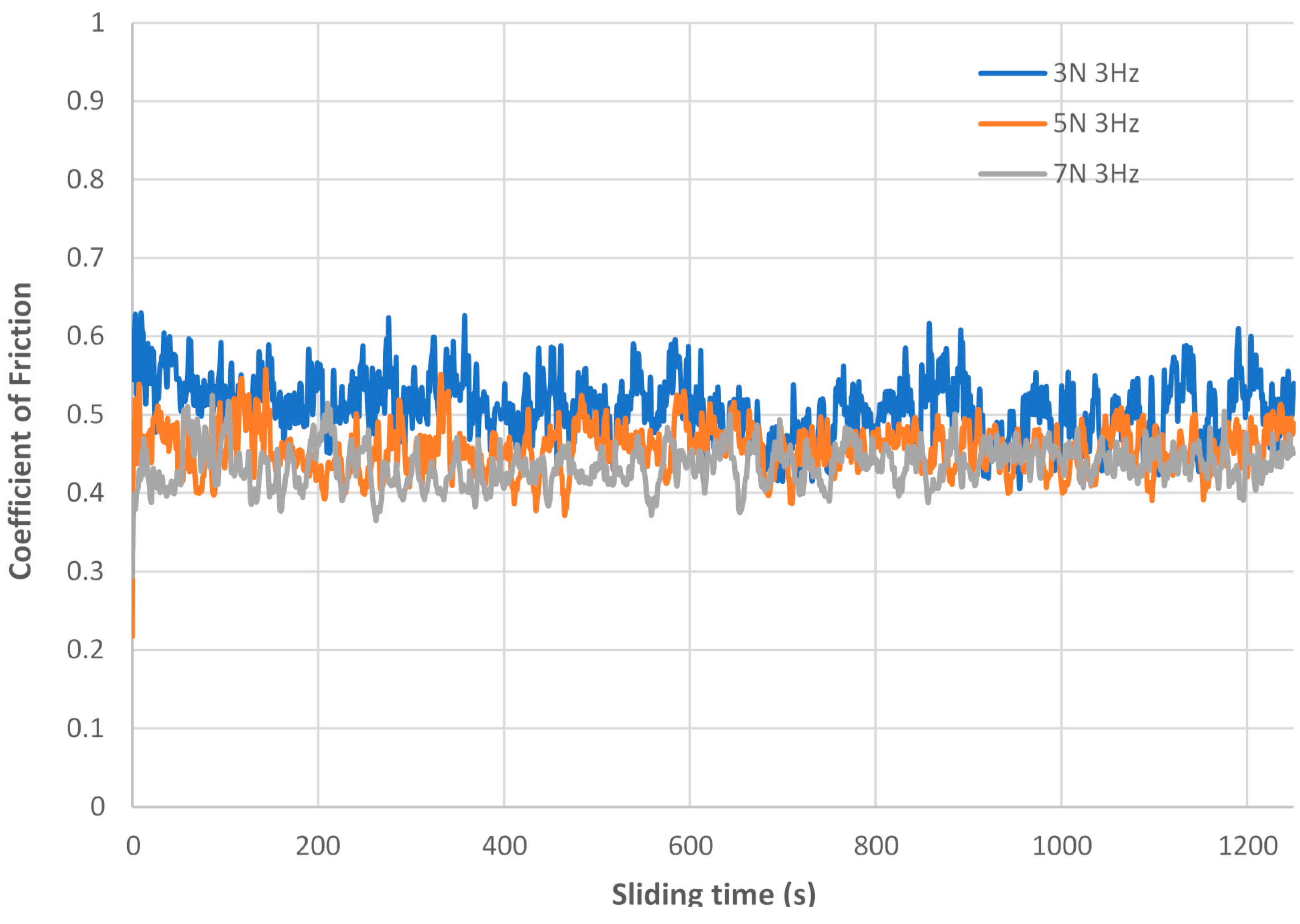
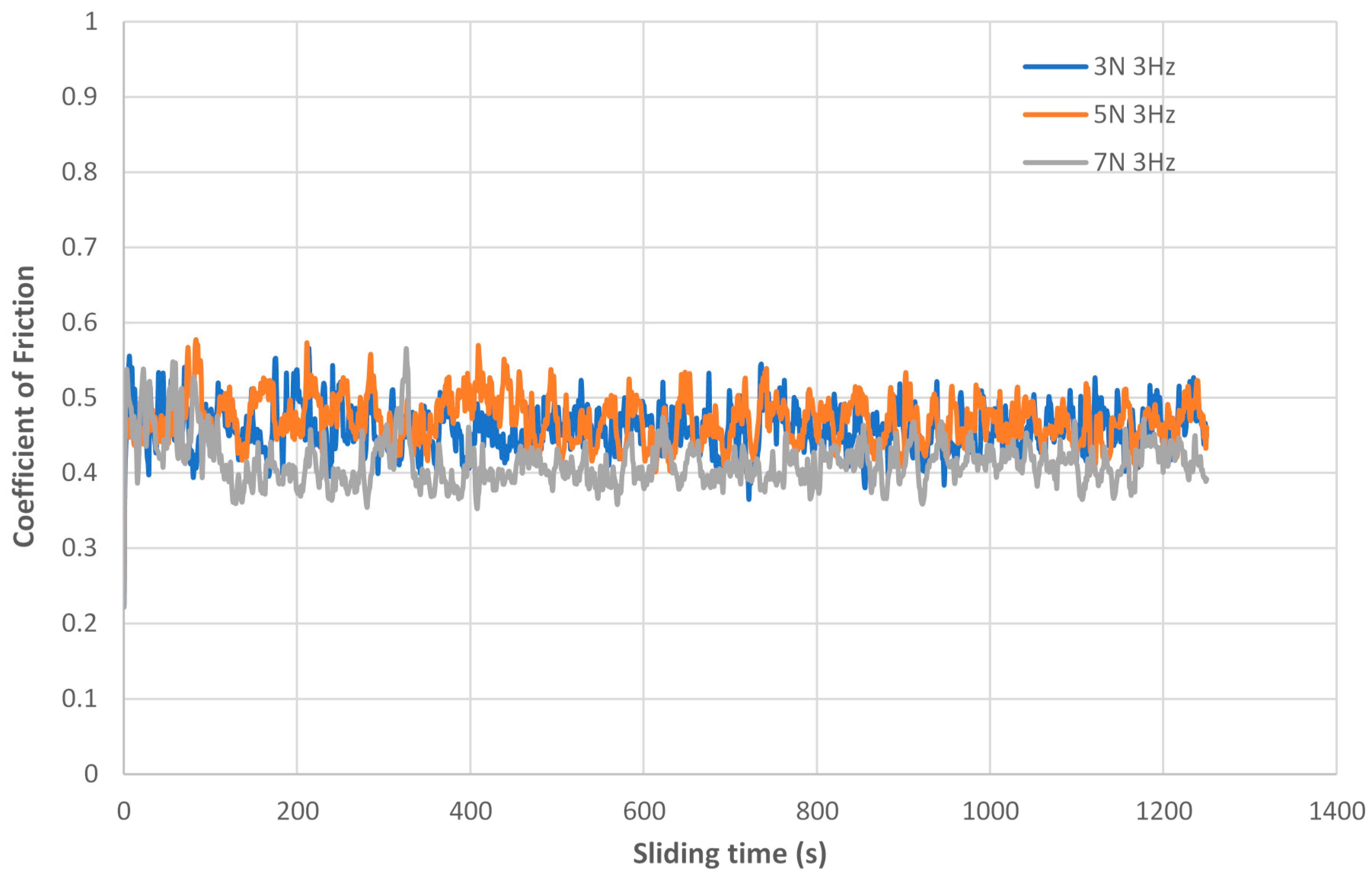
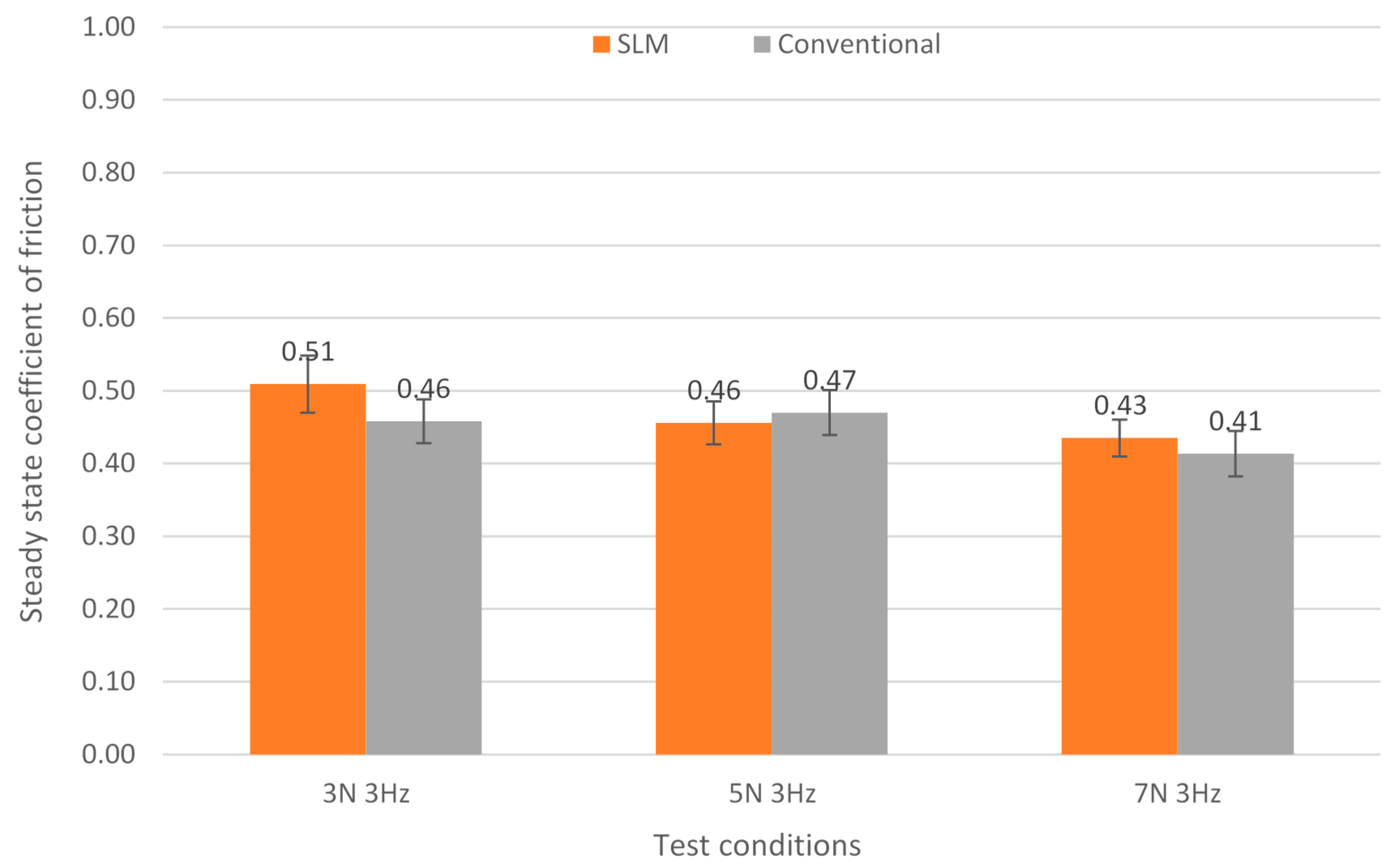
3.1. Friction Behaviour
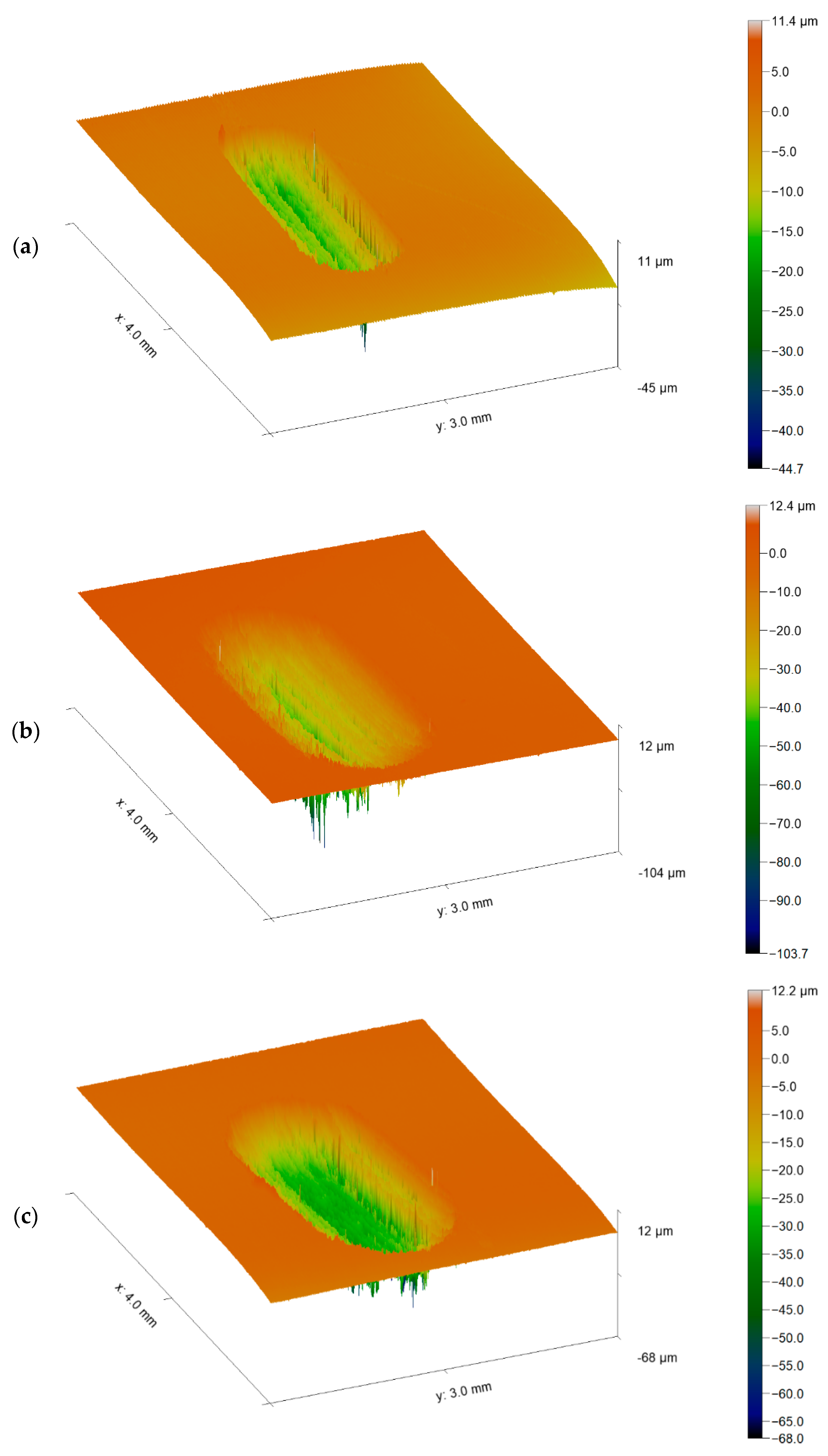
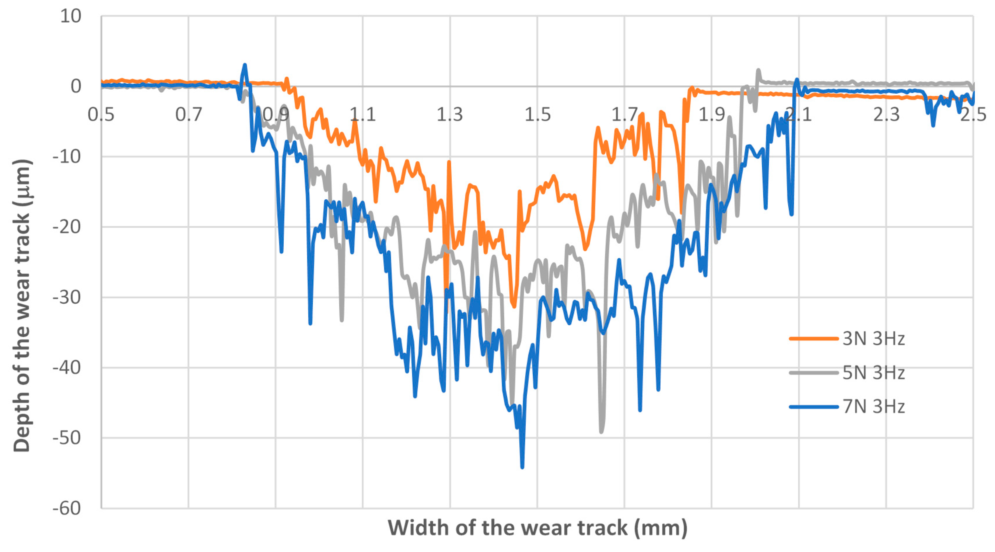
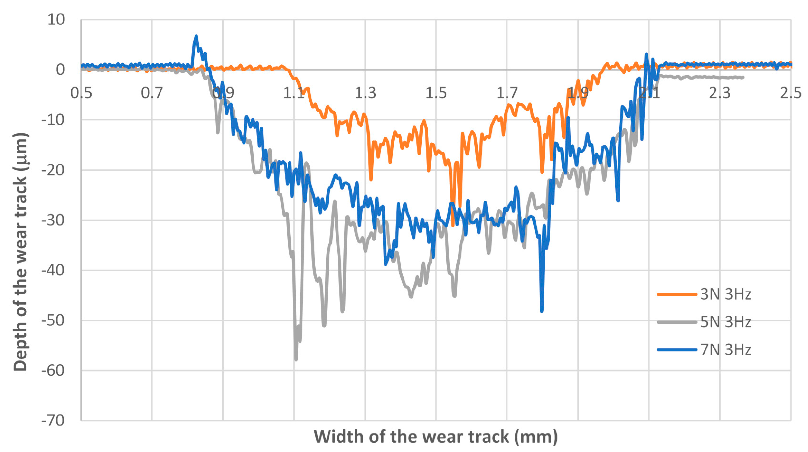
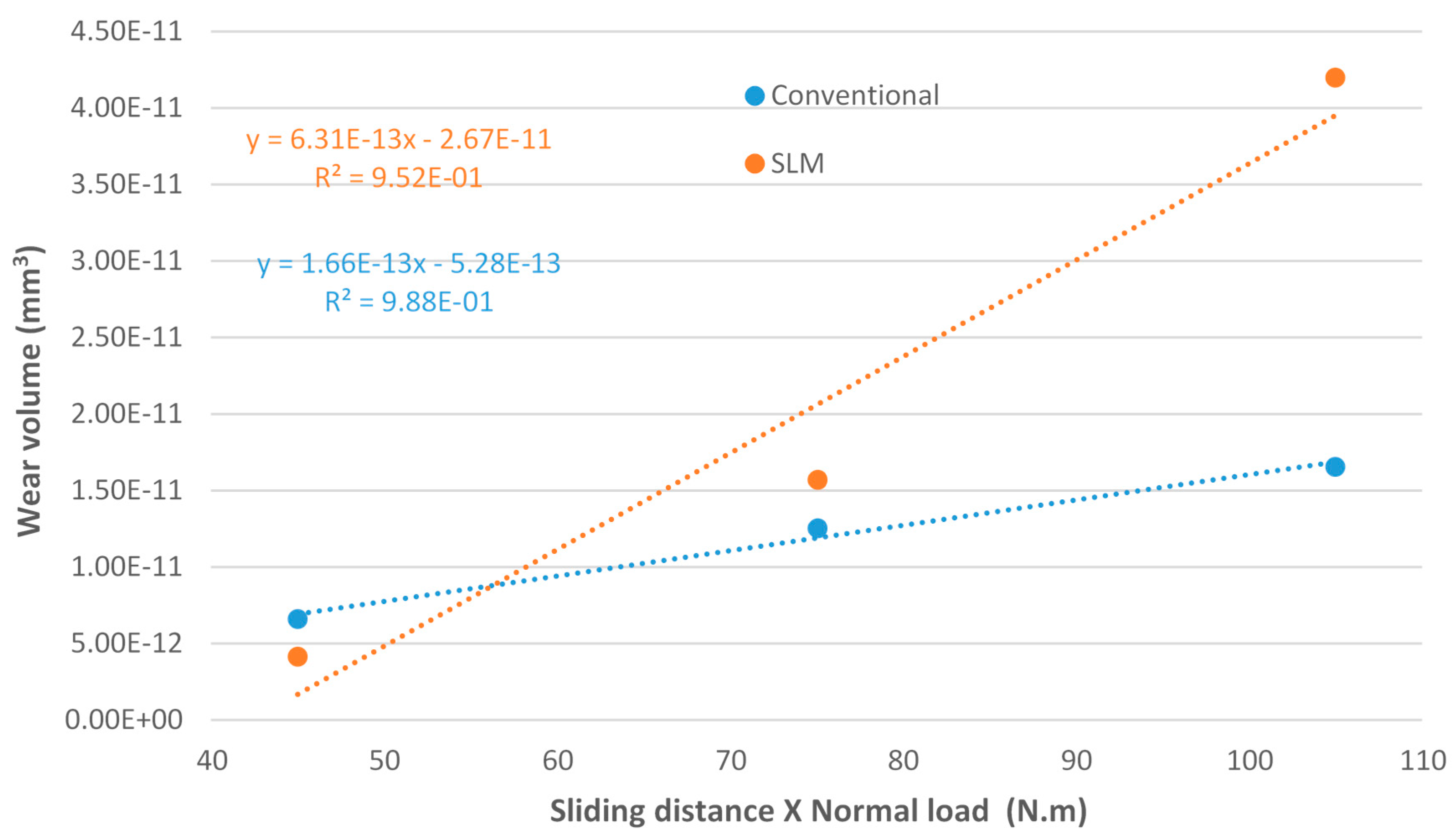
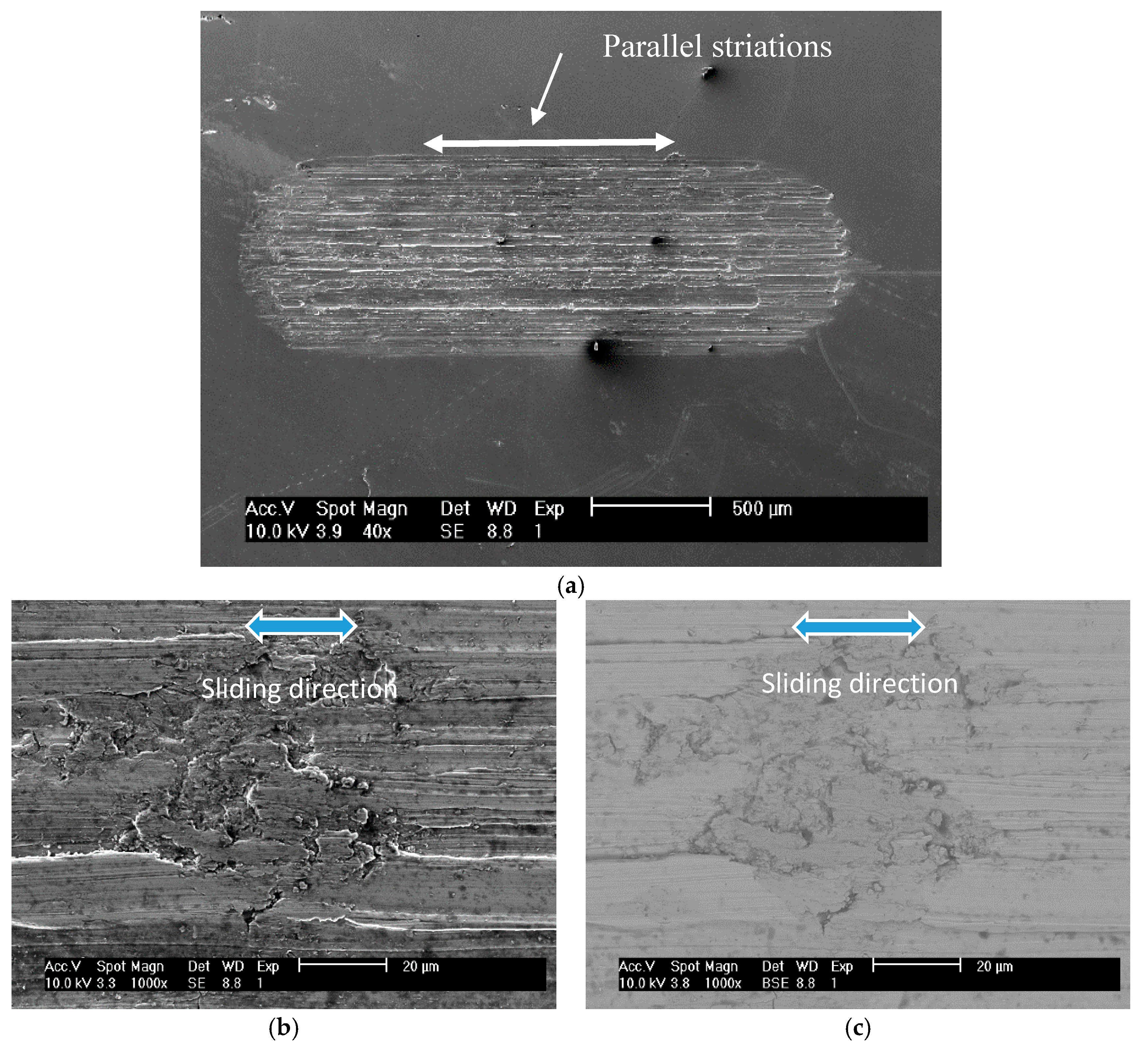
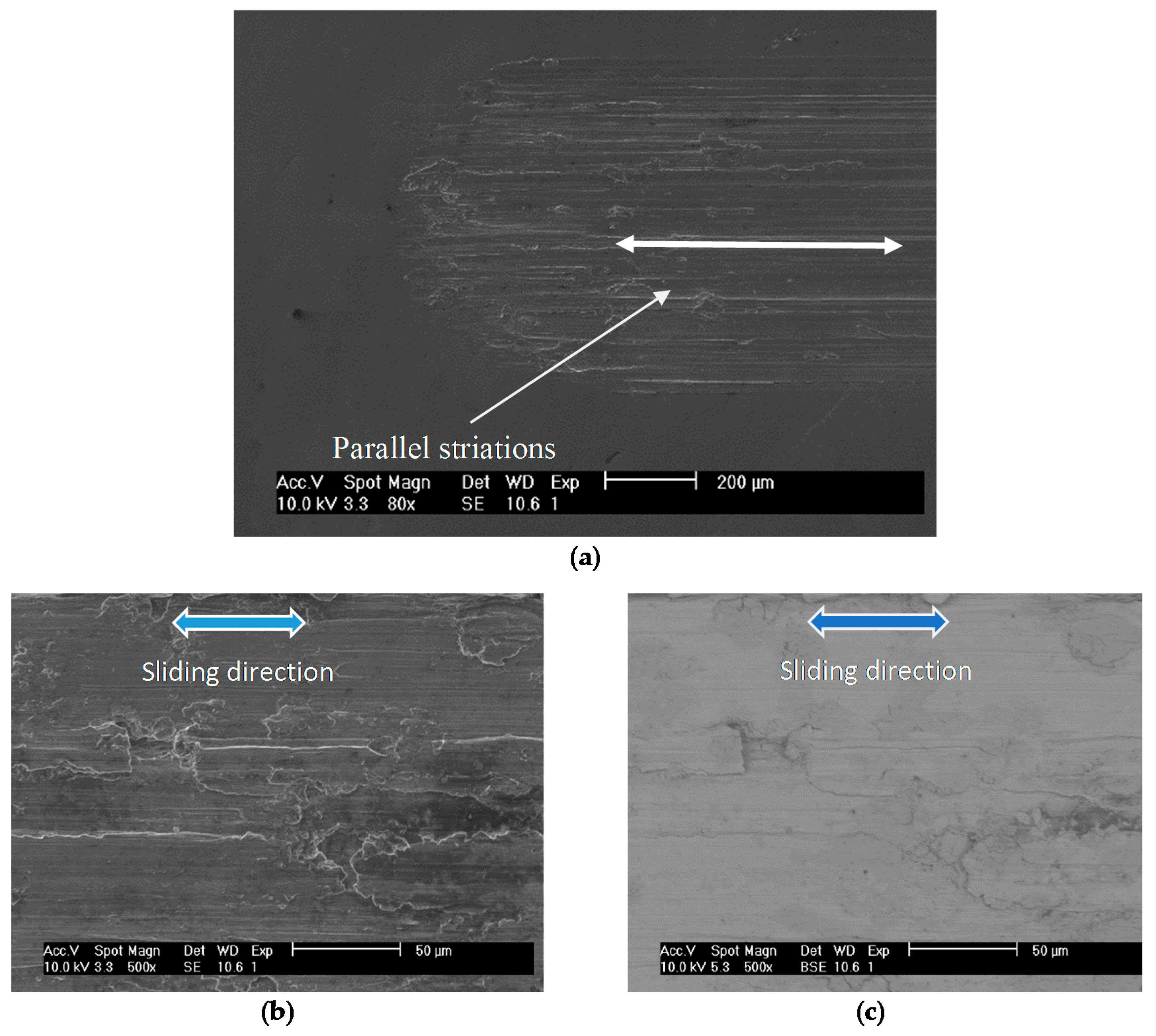
Figure 5 and Figure 6 show the evolution of the coefficient of friction (COF) with the sliding time for the reciprocating sliding tests, for both Ti6Al4V specimens, under three different applied loads (3, 5 and 7 N) and lubricated with artificial saliva. It can be seen that the COF doesn’t vary much with the applied load and stays stable throughout the entire test, for both specimens. Figure 7 shows the steady state coefficient of friction and respectively standard deviations values. It can be observed that the COF varies for both specimens between a maximum value of 0.51 and a minimum of 0.41. It can be concluded, that the difference in the microstructures of Ti6Al4V specimens doesn’t affect substantially the friction behaviour which has approximately the same performance if one considers the standard deviation values shown in the error bars.

3.2. Wear Behaviour

Figure 8 and Figure 9 show the 3 D profiles of the wear tracks obtained, sliding a TiO2 ball under a 3, 5 and 7 N applied load onto a Ti6Al4V specimen produced respectively, by SLM and conventionally. The cross section profiles that were taken in the middle of the wear tracks can be seen in Figure 10 and Figure 11. It is possible to observe that in general, the depth and diameter of the wear scars increases with the increasing load, exception made for the cross section profiles presented in Figure 11 for 5 and 7 N applied load that seems to be of the same order. In order to calculate the wear volume, each wear track was integrated using a laser stylus profilometer. Figure 12 presented the wear volume as a function of the sliding distance times the normal load for three different applied loads and both Ti6Al4V specimens. It can be seen, that the wear volume increases with the applied load (the sliding distance was kept constant and equal to 15 m) for both specimens. By fitting an equation to the data points presented in Figure 13, it is possible to determine the wear rate coefficient, k (mm3/N m) which is the same as saying that is the slope of each equation. It can be concluded that the slope for the conventional produced specimen is slightly higher, with a value of 8.3 × 10⁻⁴ mm3/Nm than that for the SLM specimen with a value of 6.3 × 10⁻⁴ mm3/Nm. However, these different values are of the same order of magnitude. On the other hand, as can be seen in Figure 13, the wear volume of the zirconia ball also increases with the increasing applied load. However, the wear rates coefficients are some minor orders of magnitude than Ti6Al4V specimens, with values of the wear rate coefficient of 6.31 × 10⁻⁴ mm3/Nm and 1.66 × 10⁻⁴ mm3/Nm for respectively Ti6Al4V obtained by SLM and Conventional way.
Figure 14 and Figure 15 show different SEM micrographs for respectively, SLM and conventional Ti6Al4V specimens. It can be concluded, that the wear mechanism is very similar, for both specimens with some grooving and parallel striations along the direction of sliding as exemplified in Figure 14a and Figure 15a. Figure 14c and Figure 15c show SEM micrographs in Back-Scattered Electron (BSE) detector mode, while Figure 14b and Figure 15b show the same SEM micrographs in Secondary Electron (SE) detector mode. It is possible to conclude from the lack of significant contrast between SE and BSE mode, that the surface is uniformly coated with the passive and protective TiO2 layer after the reciprocating sliding tests have occurred where depassivation happens due to the rubbing process. According to Walczak et al. [29], one would expect more pronounced ridging from the increased β phase since the plasticity of the β phase is higher than that of α phase, which, in turn, leads to a local increase in plastic deformation. However, it appears to be very similar to each other, especially as the SLM can be having significantly lesser β phase than their traditional counterpart.
Even if abrasive wear is the dominant mechanism observed in Ti6Al4V, it can be detect the occurrence of some points of adhesive phenomena resulting from the plastic deformation of secondary wear products.

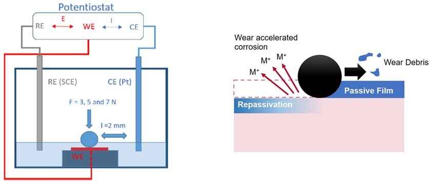
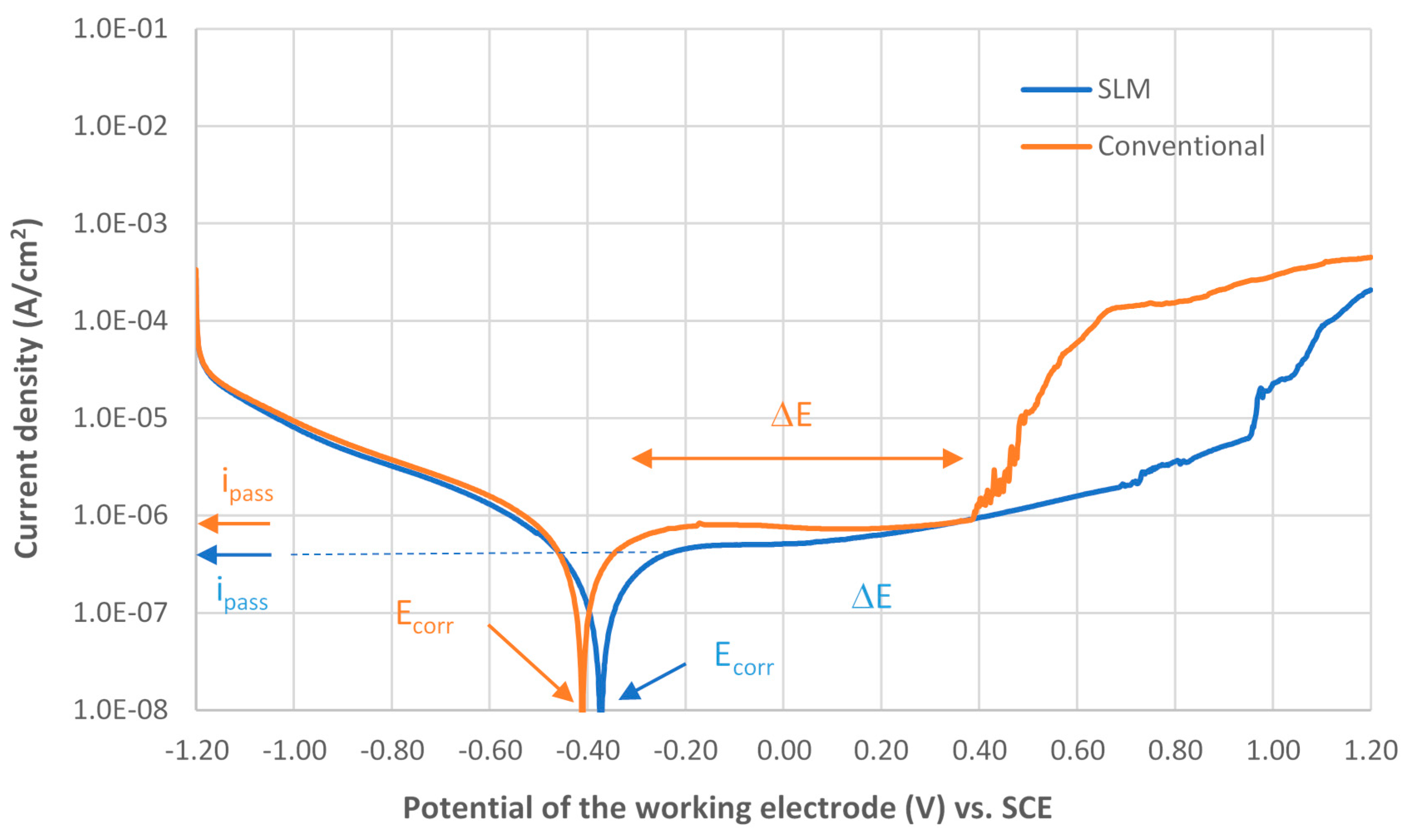
3.3. Electrochemical Behaviour

3.3.1. Potentiodynamic Polarization Curves

Figure 16 shows potentiodynamic polarization curves for Ti6Al4V alloy produced by a conventional method and by the selective laser melting (SLM) process, immersed in artificial saliva. In these curves, it can be seen the evolution of the current density with the varying potential of the working electrode. These curves are composed by one cathodic branch and by one anodic branch. Often, for passive films, these curves are characterize by parameters like, the passive current density (ipass) and potential range of the passive film (ΔE), as shown in the graphic of Figure 16.
By analysing Figure 16, it can be concluded that the specimen produced by conventional methods (orange line) presents a potential range of the passive film (ΔE) between −0.3 V and 0.4 V vs. SCE, where the passive current density (ipass) remains approximately constant with a value of 0.74 µA/cm2 due to the formation of a stable protective passive film composed of a very thin oxide layer of TiO2. At high anodic potentials, extremely high current densities were observed due to the dissolution of the TiO2 protective film, probably from the attack of chloride ions in the electrolyte enhancing corrosion. On the other hand, the specimen produced by SLM (blue line) does not lose its protective oxide layer as fast as the conventional specimen since the transpassivation domain starts at higher potential values with the potential range of the passive film being between −0.25 V and 0.72 V vs. SCE and passive current density of approximately 0.46 µA/cm2. However, the specimen produced by SLM shows a less flat plateau than the conventional specimen.
All the electrochemical parameters collected from the data presented in Figure 16 can be observed at Table 6.
Figure 17 shows a schematic picture of the Ti6Al4V SLM producing process with: (a) the different successive layers altering the laser scan direction of an angle of 90° between adjacent layers and, (b) the building direction (Z-axis) and the different planes.
An investigation into SLM produced Ti6Al4V specimens, performed by Nianwei et al. [18], showed higher corrosion resistance in the direction of the build (upwards, XY-plane), concluding that this property can be anisotropic. They also reported more pits in the XZ-plane indicating that the resistance of the passive film it’s lower than for the other plan. However, during the present research work, only the XY-plane (normal to the building direction) was investigated and compared with conventional produced specimens.
According to Nianwei et al. [18], during the production of SLM Ti6Al4V alloy, there is a higher occurrence of acicular α′ martensitic and less β-Ti phase, as shown in Figure 2, which is distinct from the conventional well-known biphasic α + β microstructure. These findings were also corroborated by our studies as demonstrated in the micrographs shown in Figure 3. Due to the higher cooling rate and thermal gradient/rapid solidification process of the SLM method, fine microstructure were obtained and improved mechanical properties than by using conventional techniques [18]. Since the corrosion resistance of different specimens is correlated with the respective microstructure, it is believed that the SLM produced specimens possess a more dense and protective film formation in order to justify this slightly corrosion resistance.

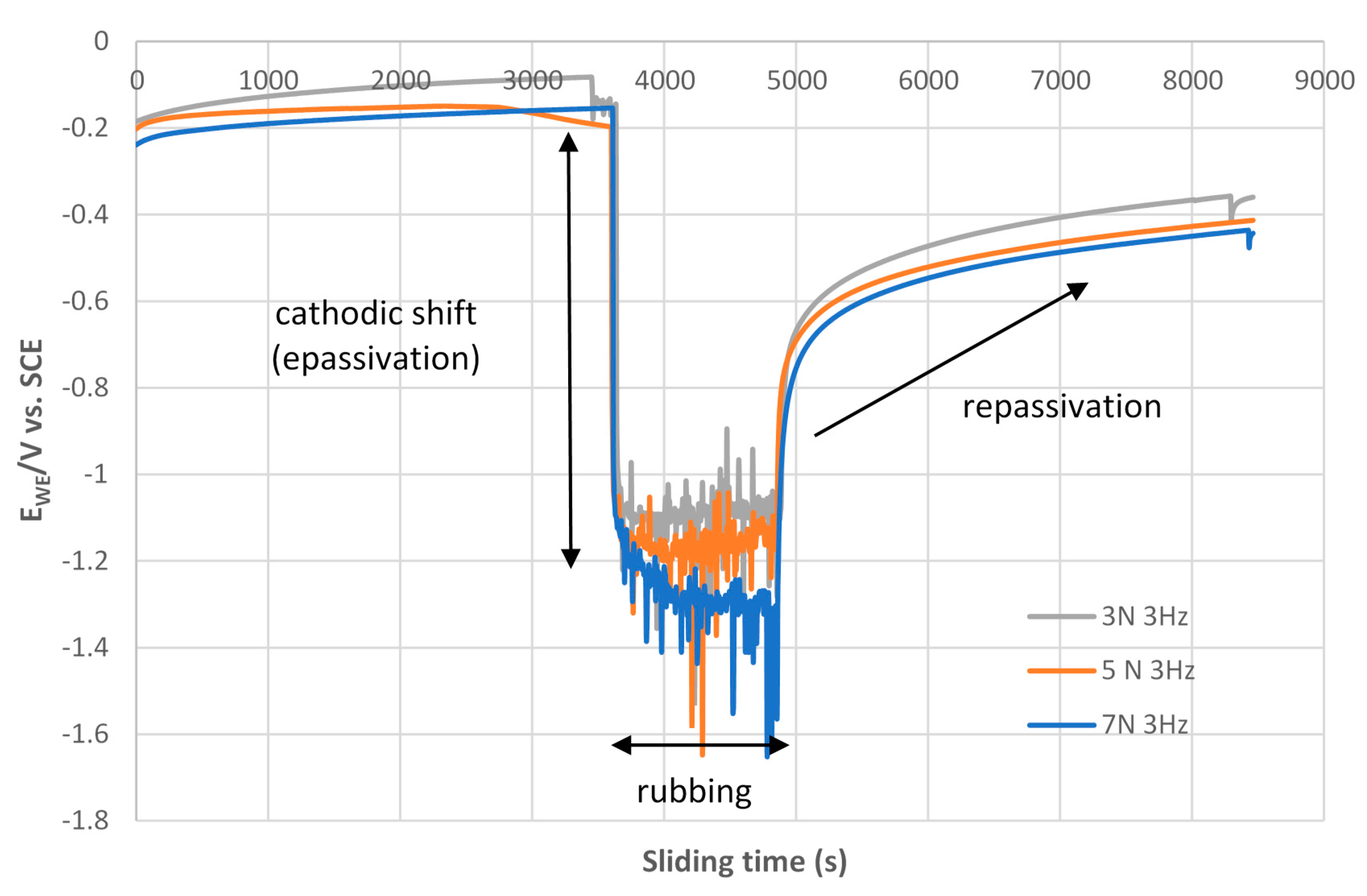
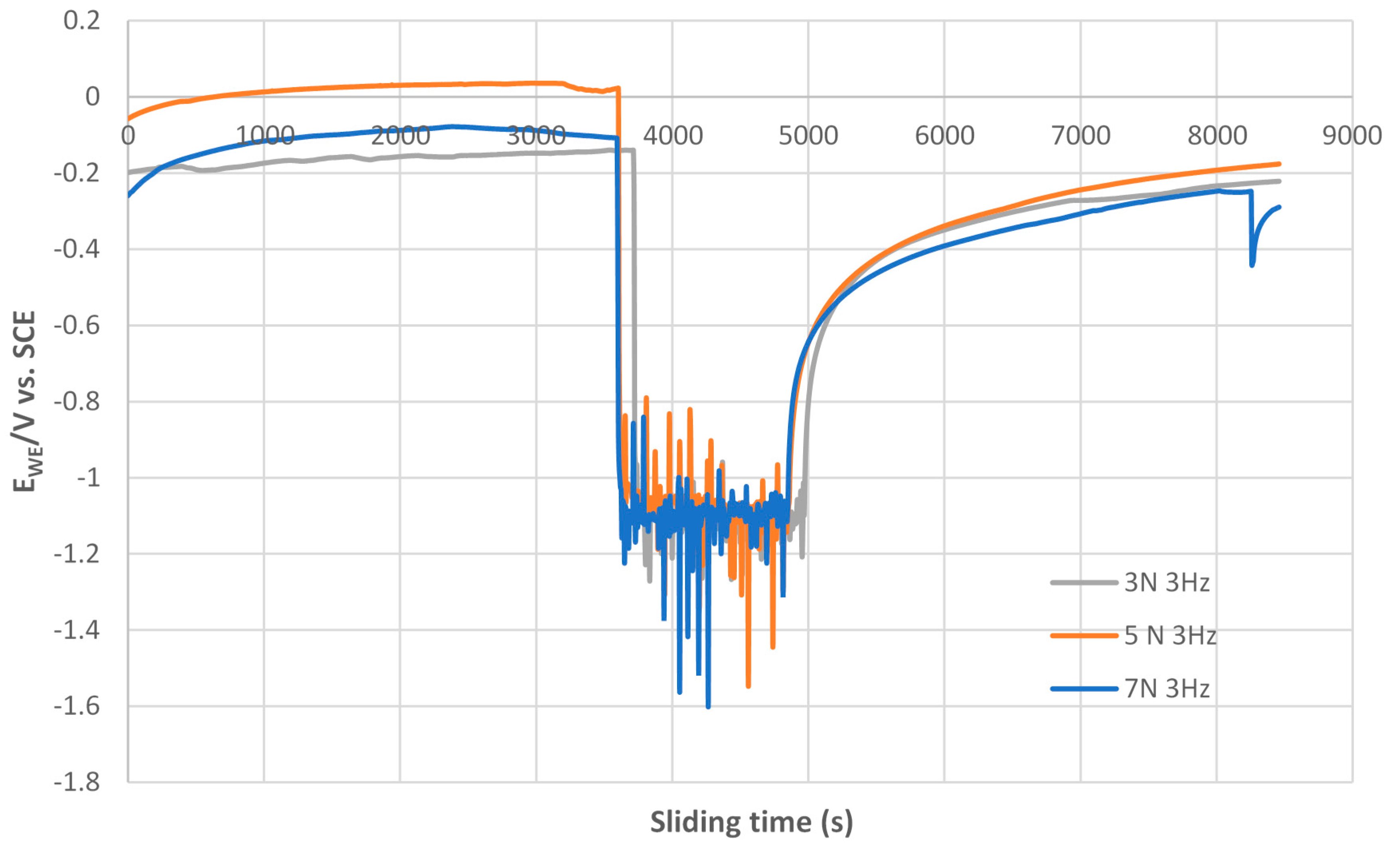
3.3.2. Open Circuit Potential (OCP) Method

Figure 18 and Figure 19 show the potential of the working electrode (EWE) as a function of the sliding time before, during and after the rubbing process. Before the sliding test begins, the samples were immersed in artificial saliva for 1 h to monitor the open circuit potential (OCP). During this time, the changes in OCP’s slope of test materials were negligible. This suggests corrosion was minimal and an oxide layer was in existence to retard metal dissolution since the samples were exposed to the artificial saliva solution. Once the samples were put under normal applied loads, and reciprocating sliding motion starts, a sharp drop in EWE indicates how fast the passive oxide layer of the test samples was physically removed with each run of a different load. This is a mixed response of the system to mechanical and chemical action as each time we remove the oxide layer, it tries to reform again, so on and so forth. When the applied load and the reciprocating sliding movement ends, the surface of the sample passivates again as it is possible to observe at Figure 18 and Figure 19 by the logarithmic shape curve on the right side of both graphics. The magnitude of EWE drop in the cathodic direction is presumed to be predominantly governed by gross slip mechanism and the strength of the passive film. The extent of the cathodic shift in both figures further confirms the onset of wear, removal of the passive protective oxide layer and increase in corrosion susceptibility of Ti6Al4V alloy in artificial saliva. The fluctuations that we see in the rapidly changing directions can be directly interpreted as proportional to shifts of anodic: cathodic free corrosion potential. This stems from the presence of passive and active galvanic couples [30]. When the sliding is stopped, the free corrosion potential shifts in the anodic direction as film re-passivates on the worn area. Restoration depends on the extent of wear and the corrosion behaviour of the alloy as a galvanic couple is formed between the unworn (anodic) and worn (cathodic) surface.
By analysing Figure 18 and Figure 19, it can be concluded that there is some sensitivity to the applied load, namely in the cathodic shift. This fact is particularly noted in Figure 19 where the cathodic shift increases with the increasing of the applied load. However, load appears to play a slight role in repassivation since the time it takes to reach the same Ewe it’s approximately the same.

4. Conclusions

The understanding gained from the present research work reinforces the idea of the synergistic effect of various forces at play, from a chemical point of view as well as tribological. The following conclusions can be drawn:
  • The mechanical and tribocorrosion behaviour of Ti6Al4V produced by SLM is significantly dependent on the scan optimization variables since the process is anisotropic. However, we have only tested the surface that is normal to the building direction.
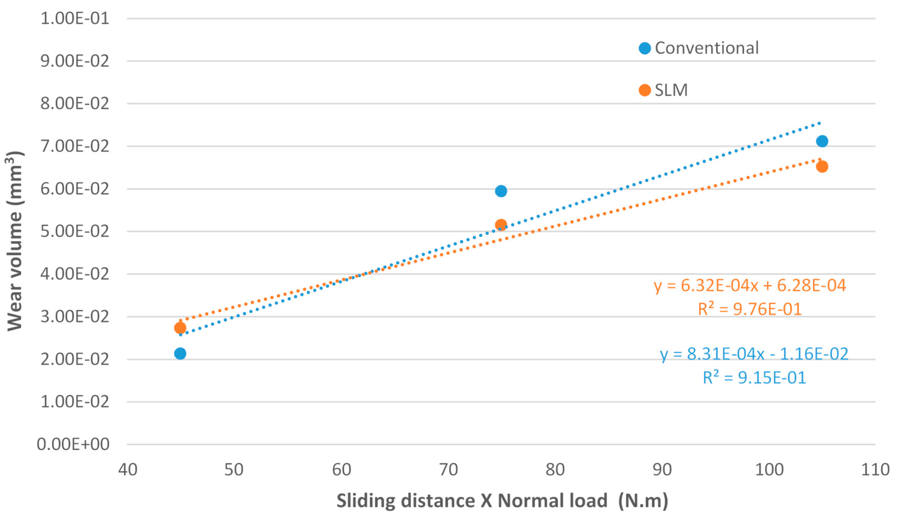
  • Regarding the tribological behaviour of the Ti6Al4V specimens obtained by SLM and conventional method, they exhibited similar COF in the order of 0.41–0.51. The wear rate coefficients (k) for Ti6Al4V obtained by SLM and conventional method are of the same order showing the following values: k (SLM) = 6.3 × 10⁻⁴ mm3/N.m and k (Conventional) = 8.3 × 10⁻⁴ mm3/N.m. The wear mechanism is mainly abrasive wear with grooves aligned in the direction of sliding.
  • The corrosion resistance of Ti6Al4V obtained by SLM is slightly higher than the corrosion resistance of Ti6Al4V obtained by conventional method. The potential range of passive film ΔE (SLM) > ΔE (conventional) that implies higher stability of the passive film; the passive current density: ipass (SLM) < ipass (conventional) that implies easy passivation of the alloy; the corrosion potential: Ecorr (SLM) > Ecorr (conventional) that implies a noble alloy.
  • Ti6Al4V can be produced by additive manufacturing methods to at least comparable mechanical and tribological properties then those obtained by conventional produced methods. Even when properties between SLM and conventional produced samples are comparable, SLM can still be a vastly superior choice simply due to its design freedom and manufacturing-flexibility advantages, provided designs are sufficiently intricate, require better quality control or/and cater to the low to medium volume production. The implant industry fits all these requirements as the demands are custom tailored to individuals. Thus, requires the utmost quality, complex osseointegration to the bone with a suitable tailored/fine-tuned porosity, and don’t need mass production.

Author Contributions

Conceptualization, L.M.V., A.R. and J.A.M.F.; Methodology, L.M.V. and A.R.; Software, A.R.; Validation, L.M.V., A.R. and J.A.M.F.; Formal Analysis, L.M.V. and A.R.; Investigation, L.M.V., A.S. and A.R.; Resources, J.A.M.F.; Data Curation, L.M.V., A.R. and J.A.M.F.; Writing-Original Draft Preparation, L.M.V. and A.R.; Writing-Review & Editing, L.M.V. and A.R.; Visualization, L.M.V. and A.R.; Supervision, L.M.V., A.R. and J.A.M.F.; Project Administration, J.A.M.F.; Funding Acquisition, J.F. All authors have read and agreed to the published version of the manuscript.

Funding

The authors would like to acknowledge the sponsoring under the project no. 028789, financed by the European Regional Development Fund (FEDER), through the Portugal-2020 program (PT2020), under the Regional Operational Program of the Center (CENTRO-01-0145-FEDER-028789) and the Foundation for Science and Technology IP/MCTES through national funds (PIDDAC).

Conflicts of Interest

The authors declare no conflict of interest.

References

  1. Oliveira, M.N.; Schunemann, W.V.H.; Mathew, M.T.; Henriques, B.; de Magini, R.S.; Teughels, W.; Souza, J.C.M. Can degradation products released from dental implants affect peri-implant tissues? J. Periodontal Res. 2018, 53, 1–11. [Google Scholar] [CrossRef]
  2. Smith, D.C. Dental implants: Materials and design considerations. Int. J. Prosthodont. 1993, 6, 106–117. [Google Scholar]
  3. Triplett, R.G.; Frohberg, U.; Sykaras, N.; Woody, R.D. Implant materials, design, and surface topographies: Their influence on Osseointegration of dental implants. J. Long Term Eff. Med. Implants 2003, 13, 485–501. [Google Scholar] [CrossRef]
  4. Anusavice, J.K.; Shen, C.; Rawls, H.R. (Eds.) Dental implants. In Phillips’ Science of Dental Materials, 12th ed.; Elsevier: Philadelphia, PA, USA, 2013; pp. 715–736. [Google Scholar]
  5. Vilhena, L.M.; Boakye, G.O.; Ramalho, A. Tribocorrosion of different biomaterials under reciprocating sliding conditions in artificial saliva. Lubr. Sci. 2019, 31, 364–380. [Google Scholar] [CrossRef]
  6. Fuentes, E.; Alves, S.; López-Ortega, A.; Mendizabal, L.; de Viteri, V.S. Advanced Surface Treatments on Titanium and Titanium Alloys Focused on Electrochemical and Physical Technologies for Biomedical Applications; IntechOpen: London, UK, 2019. [Google Scholar] [CrossRef] [Green Version]
  7. Mathew, M.T.; Pai, P.S.; Pourzal, R.; Fischer, A.; Wimmer, M.A. Significance of Tribocorrosion in Biomedical Applications: Overview and Current Status. Adv. Tribol. 2009, 2009, 250986. [Google Scholar] [CrossRef] [Green Version]
  8. Landolt, D.; Mischler, S. Tribocorrosion of Passive Metals and Coatings; Woodhead Publishing: Cambridge, UK, 2011; ISBN 978-1-84569-966-6. [Google Scholar]
  9. Watson, S.W.; Friedersdorf, F.J.; Madsen, B.W.; Cramer, S.D. Methods of measuring wear-corrosion synergism. Wear 1995, 181–183, 476–484. [Google Scholar] [CrossRef]
  10. Mischler, S.; Rosset, E.A.; Landolt, D. Effect ofCorrosion on theWear Behavior of PassivatingMetals in Aqueous Solutions. Tribol. Interface Eng. Ser. 1993, 25, 245–253. [Google Scholar]
  11. G119-09 ASTM. Standard Guide for Determining Synergism Between Wear and Corrosio; ASTM International: West Conshohocken, PA, USA, 2016. [Google Scholar]
  12. Landolt, D. Electrochemical and materials aspects of tribocorrosion systems. J. Phys. D Appl. Phys. 2006, 39, 3121–3127. [Google Scholar] [CrossRef]
  13. Landolt, D.; Mischler, S.; Stemp, M. Electrochemical methods in tribocorrosion: A critical appraisal. Electrochim. Acta 2001, 46, 3913–3929. [Google Scholar] [CrossRef]
  14. López-Ortega, A.; Arana, J.L.; Bayón, R. Tribocorrosion of Passive Materials: A Review on Test Procedures and Standards. Int. J. Corros. 2018, 2018, 7345346. [Google Scholar] [CrossRef]
  15. Cassar, J.; Mallia, B.; Mazzonello, A.; Karl, A.; Buhagiar, J. Improved Tribocorrosion Resistance of a CoCrMo Implant Material by Carburising. Lubricants 2018, 6, 76. [Google Scholar] [CrossRef] [Green Version]
  16. Wysocki, B.; Maj, P.; Sitek, R.; Buhagiar, J.; Kurzydłowski, K.; Święszkowski, W. Laser and electron beam additive manufacturing methods of fabricating titanium bone implants. Appl. Sci. 2017, 7, 657. [Google Scholar] [CrossRef]
  17. Liu, S.; Shin, Y.C. Additive manufacturing of Ti6Al4V alloy: A review. Mater. Des. 2019, 164, 107552. [Google Scholar] [CrossRef]
  18. Dai, N.; Zhang, L.-C.; Zhang, J.; Zhang, X.; Ni, Q.; Chen, Y.; Wu, M.; Yang, C. Distinction in corrosion resistance of selective laser melted Ti-6Al-4V alloy on different planes. Corros. Sci. 2016, 111, 703–710. [Google Scholar] [CrossRef] [Green Version]
  19. Mullen, L.; Stamp, R.C.; Brooks, W.K.; Jones, E.; Sutcliffe, C.J. Selective laser melting: A regular unit cell approach for the manufacture of porous, titanium, bone in-growth constructs, suitable for orthopaedic applications. J. Biomed. Mater. Res. B 2009, 89, 325–334. [Google Scholar] [CrossRef] [PubMed]
  20. Zhang, L.C.; Klemm, D.; Eckert, J.; Hao, Y.L.; Sercombe, T.B. Manufacture by selective laser melting and mechanical behavior of a biomedical Ti-24Nb-4Zr-8Sn alloy. Scripta Mater. 2011, 65, 21–24. [Google Scholar] [CrossRef]
  21. Attar, H.; Prashanth, K.G.; Chaubey, A.K.; Calin, M.; Zhang, L.C.; Scudino, S.; Eckert, J. Comparison of wear properties of commercially pure titanium prepared by selective laser melting and casting processes. Mater. Lett. 2015, 142, 38–41. [Google Scholar] [CrossRef]
  22. Attar, H.; Bönisch, M.; Calin, M.; Zhang, L.C.; Scudino, S.; Eckert, J. Selective laser melting of in-situ titanium-titanium boride composites: Processing, microstructure and mechanical properties. Acta Mater. 2014, 76, 13–22. [Google Scholar] [CrossRef]
  23. Liu, Y.J.; Li, X.P.; Zhang, L.C.; Sercombe, T.B. Processing and properties of topologically optimised biomedical Ti-24Nb-4Zr-8Sn scaffolds manufactured by selective laser melting. Mater. Sci. Eng. A 2015, 642, 268–278. [Google Scholar] [CrossRef]
  24. Thijs, L.; Verhaeghe, F.; Craeghs, T.; Humbeeck, J.V.; Kruth, J.P. A study of the microstructural evolution during selective laser melting of Ti-6Al-4V. Acta Mater. 2010, 58, 3303–3312. [Google Scholar] [CrossRef]
  25. Sallica-Leva, E.; Jardini, A.L.; Fogagnolo, J.B. Microstructure and mechanical behavior of porous Ti-6Al-4V obtained by selective laser melting. J. Mech. Behav. Biomed. Mater. 2013, 26, 98–108. [Google Scholar] [CrossRef] [PubMed]
  26. Tamilselvi, S.; Raman, V.; Rajendran, N. Corrosion behaviour of Ti-6Al-7Nb and Ti-6Al-4V ELI alloys in the simulated body fluid solution by electrochemical impedance spectroscopy. Electrochim. Acta 2006, 52, 839–846. [Google Scholar] [CrossRef]
  27. Branquinho, A.N. Análise da Propagação de Fendas por Fadiga em Provetes de Titânio Obtidos por Fusão Seletiva por Laser. Master’s Thesis, University of Coimbra, Coimbra, Portugal, 2018. Available online: http://hdl.handle.net/10316/86066 (accessed on 17 December 2019).
  28. Madyira, D.M.; Laubscher, R.F.; van Rensburg, N.J.; Henning, P.F.J. High speed machining induced residual stresses in Grade 5 titanium alloy. Proc. Inst. Mech. Eng. Part L J. Mater. Des. Appl. 2013, 227, 208–215. [Google Scholar] [CrossRef]
  29. Walczak, M.; Drozd, K. Tribological characteristics of dental metal biomaterials. Curr. Issues Pharm. Med. Sci. 2016, 29, 158–162. [Google Scholar] [CrossRef] [Green Version]
  30. Papageorgiou, N.; Mischler, S. Electrochemical Simulation of the Current and Potential Response in Sliding Tribocorrosion. Tribol. Lett. 2012, 48, 271–283. Available online: https://link.springer.com/article/10.1007/s11249-012-0022-9 (accessed on 17 December 2019). [CrossRef]
Figure 1. Schematic picture showing the synergy between wear and corrosion for Ti6Al4V during sliding wear [15].
Lubricants 08 00022 g001
Figure 2. Typical microstructure of Ti6Al4V produced by SLM showing the acicularα’ [18].
Lubricants 08 00022 g002
Figure 3. Micrographs of Ti6Al4V produced by SLM obtained by Optical Microscopy with different magnifications: (a) 100×; (b) 500×.
Lubricants 08 00022 g003
Figure 4. Schematic setup of the tribocorrosion cell showing the working electrode (WE), reference electrode (RE) and counter electrode (CE) connected to a potentiostat and sliding against a zirconia ball under different contact conditions.
Lubricants 08 00022 g004
Figure 5. Evolution of the coefficient of friction (COF) with the sliding time for Ti6Al4V alloy produced by the selective laser melting (SLM) process rubbing against a zirconia ball with different applied loads (3, 5 and 7 N).
Lubricants 08 00022 g005
Figure 6. Evolution of the coefficient of friction (COF) with the sliding time for Ti6Al4V alloy produced by a conventional method rubbing against a zirconia ball with different applied loads (3, 5 and 7 N).
Lubricants 08 00022 g006
Figure 7. Evolution of the steady state coefficient of friction with applied load (3, 5 and 7 N) for Ti6Al4V alloy produced by a conventional method and by a selective laser melting (SLM) process, rubbing against a zirconia ball.
Lubricants 08 00022 g007
Figure 8. 3D profiles of the wear tracks for the Ti6Al4V alloy produced by selective laser melting process rubbing against a zirconia ball for different applied loads: (a) 3, (b) 5 and (c) 7 N.
Lubricants 08 00022 g008
Figure 9. 3D profiles of the wear tracks for the Ti6Al4V alloy produced by conventional method rubbing against a zirconia ball for different applied loads: (a) 3, (b) 5 and (c) 7 N.
Lubricants 08 00022 g009
Figure 10. Cross-section profiles of the wear tracks for the Ti6Al4V alloy produced by selective laser melting process rubbing against a zirconia ball for different applied loads: (3, 5 and 7 N).
Lubricants 08 00022 g010
Figure 11. Cross-section profiles of the wear tracks for the Ti6Al4V alloy produced by conventional method rubbing against a zirconia ball for different applied loads: (3, 5 and 7 N).
Lubricants 08 00022 g011
Figure 12. Wear volume as a function of the sliding distance times the normal load for the Ti6Al4V discs sliding against a zirconia ball under 3, 5 and 7 N applied load and 15 m sliding distance.
Lubricants 08 00022 g012
Figure 13. Wear volume as a function of the sliding distance times the normal load for the zirconia ball sliding against Ti6Al4V discs under 3, 5 and 7 N applied load and 15 m sliding distance.
Lubricants 08 00022 g013
Figure 14. SEM micrographs of the wear tracks for the Ti6Al4V alloy produced by selective laser melting (SLM) process rubbing against a zirconia ball (the building direction is normal to the tested surface/sliding direction).
Lubricants 08 00022 g014
Figure 15. SEM micrographs of the wear tracks for the Ti6Al4V alloy produced by conventional method rubbing against Zirconia ball.
Lubricants 08 00022 g015
Figure 16. Potentiodynamic polarization curves for Ti6Al4V alloy produced by a conventional method and by a selective laser melting (SLM) process, tested in artificial saliva at a scan rate = 1 mV/s.
Lubricants 08 00022 g016
Figure 17. Schematic picture of: (a) Laser scan direction and; (b) 3D diagram showing the different planes of SLM produced Ti6Al4V [18].
Lubricants 08 00022 g017
Figure 18. Open circuit potential (OCP) curves before, during and after rubbing process, sliding against Ti6Al4V alloy produced by a conventional method rubbing against a zirconia ball for different applied loads (3, 5 and 7 N) tested in artificial saliva.
Lubricants 08 00022 g018
Figure 19. Open circuit potential (OCP) curves before, during and after rubbing process, sliding against Ti6Al4V alloy produced by a selective laser melting process rubbing against zirconia ball for different applied loads (3, 5 and 7 N) tested in artificial saliva.
Lubricants 08 00022 g019
Table 1. Chemical composition in Weight (%) of titanium alloy Ti6Al4V specimens produced by SLM and conventional method.
Chemical ElementAlVFeCONHTi
Ti6Al4V SLM6.24.10.170.060.140.030.009Remainder
Ti6Al4V Conventional640.20.10.20.030.01589.45
Table 2. Mechanical Properties of the Ti6Al4V specimens produced by SLM [27] and conventional method (ASTM F136) [28].
Hardness [HV]
Kgf/mm2
Young’s Modulus [GPa]Yield Strength [MPa]Tensile Strength [MPa]
35812010001147
3491159391027
Table 3. Chemical composition of the artificial saliva used as lubricant/electrolyte (pH = 6.5).
CompoundContent (g/L)
NaCl0.600
KCl0.720
CaCl2.2H2O0.220
KH2PO40.680
Na2HPO4.12H2O0.856
KSCN0.060
NaHCO31.500
Citric acid0.030
Table 4. Sequences used during the open circuit potential (OCP) method.
StepDescriptionTime (s)
1Open circuit potential (OCP)3600
2Open circuit potential (OCP) with tribological experiment (reciprocating sliding)1250 (3 Hz)
3Restabilization of the system3600
Table 5. Sequences used during the potentiodynamic polarization method.
StepDescriptionTime (s)
1Stabilization of the system under open circuit potential (OCP)3600
2Potentiodynamic polarization (−1200 mV to +1200 mV vs. SCE) (scan rate = 1 mV/s)2400
Table 6. Electrochemical parameters: Corrosion potential (Ecorr), passive current density (ipass), potential range of the passive film (ΔE) and corrosion rate for both Ti6Al4V specimens investigated.
SpecimenEcorr
(V vs SCE)
ipass
(µA/cm2)
ΔE
(V vs SCE)
Corrosion Rate
(mm/year)
SLM−0.370.46−0.25 to +0.721.86 × 10−3
Conventional−0.400.74−0.29 to + 0.383.37 × 10−3

