Article

Harsh Sliding Wear of a Zirconia Ball against a-C:H Coated CoCrMo Disc in Hyaluronic Gel

by
Annett Dorner-Reisel
1,*,
Christian Schürer
2 and
Stefan Svoboda
3
1
Faculty of Mechanical Engineering, Schmalkalden University of Applied Sciences, Blechhammer 4-9, D-98754 Schmalkalden, Germany
2
Consultant Chemnitz, Germany, Oberfrohnaer Straße 16a, D-09117 Chemnitz, Germany
3
Faculty of Electrical Engineering, University of Applied Sciences Schmalkalden, Blechhammer 4-9, D-98754 Schmalkalden, Germany
*
Author to whom correspondence should be addressed.
Lubricants 2020, 8(3), 35; https://doi.org/10.3390/lubricants8030035
Submission received: 13 January 2020 / Revised: 12 February 2020 / Accepted: 6 March 2020 / Published: 23 March 2020
(This article belongs to the Special Issue Tribology of Biomaterials)

Abstract

:
The a-C:H (amorphous carbon-hydrogen) films belong to the family of DLC (diamond-like carbon) coatings. The a-C:H coating was deposited on medical grade CoCrMo substrates by plasma-assisted chemical vapor deposition (PA-CVD) using benzene as gaseous precursor. Benzene offers an aromatic structure, which affects the a-C:H properties after plasma decomposition. A zirconia ball was sliding at two different frequencies, 50 Hz or 1Hz, against the uncoated and a-C:H coated CoCrMo. The frequency of 1 Hz is typical for human movement during fast walking. The harsh sliding conditions with a normal load of 100 N and 50 Hz frequency simulate extreme overloading of the biomedical sliding partners. It gives insight into the failure mechanisms. The wear tests were carried out in laboratory air (dry, RH: 15.6%) or using hyaluronic gel as lubricant. The hyaluronic gel acts as an effective intermediate medium. It adheres very well to both, a-C:H coating and zirconia. No wear was evident on the ZrO2 ball at 1 Hz and 100 N. Minor wear traces were observed on the a-C:H coating only. A wear coefficient of 0.16 × 10⁻⁶ mm3/N·m were calculated for a-C:H coated CoCrMo after ZrO2 ball sliding with 1 Hz and 100 N in hyaluronic gel. This is two orders of magnitude lower in comparison to dry sliding of ZrO2 ball against DLC coated CoCrMo with 1 Hz. The coefficient of friction (COF) remained below 0.09 until the hyaluronic gel starts to lose viscosity. This finding pronounces the importance of a proper homogeneous lubrication during operation of the biomedical joints. For extreme harsh tribological loading like sudden jumps of a patient with artificial joints, the application of an intermediate layer before a-C:H coating needs further evaluation.

1. Introduction

Hyaluronic acid is the main component of synovial liquid, the lubricating substance between articulating partners in natural joints. It provides ultra-low friction. Synovia is a viscous body fluid with clear appearance. It is produced by the membrana synovialis, which covers the articular capsule inside. During loading and movement of the femur, synovial liquid is squeezed out into the natural joints. Kung et al. [1] describe the importance of preserving the integrity of joint including the synovial lining and natural lubricating fluid properties for future successful implant survivorship.
Artificial joints contain CoCrMo alloys often, because of their wear resistance. The metallic CoCrMo is either just a part of the articulating joint, like the ball in a hip joint or the femur in a knee joint, or both articulating partners are made of metallic CoCrMo. Although artificial joint implants are produced on a high quality level already, some problems can arise from metallic ions or wear particles [2]. Blood cobalt and chromium levels of greater than 7 ppb (7 μg/L), point to potential for undesired soft tissue reaction [2]. Even if, the articulating part in the artificial joint is a softer polymer, like UHMWPE (ultra-high molecular weight polyethylene), the metallic counterpart suffers from wear. Alternatively, special designed surface modifications—i.e., inorganic carbon allotropes—can be applied to reduce ion and wear particle release. Care must be taken in order to ensure proper adherence and durability of surface modifications.
The motivation of the present study is exploring the suitability and limits of a potential surface modification by diamond-like carbon coatings on CoCrMo metallic alloy. As mentioned before, medical grade CoCrMo implants over excellent wear resistance under proper conditions, but as a partner in the articulating couple, they slowly are abraded to a certain extent. A DLC coating should reduce their abrasive wear. Furthermore, DLC as a carbon surface modification could provide sufficient hosting for synovia in artificial joints. Inorganic carbon modifications are known to provide proper hosting conditions for body liquids and tissues with a broad range of properties [3,4,5,6,7]. Fuhrer et al. [3] produce 3D glassy carbon scaffolds by pyrolysis for culturing neural stem cells (NSCs). The successful cultivation of NSCs were proven by magnetic resonance imaging. Glassy carbon acted as an electrode material, which is able to provide electrical stimulus to the cells. Patel et al. [4] describe, that carbon nanotube carpets facilitating myoblast, which are precursors for later muscle cell differentiation, adhesion. As reported by Eivazzadeh-Keihan et al. [5], graphene and graphene oxide (GO) attract the attention of medical experts in bone regeneration and other fields of tissue engineering, because GO in polymer matrix provides a positive stimulus on the bone mineralization process. Diamond is known as a biointert material. Stankova et al. [6] were reinforcing polymeric scaffolds with diamond nanoparticles. They point out the cell behavior on diamond nanoparticle loaded scaffolds is markedly influences by the origin and the properties of the diamond nanoparticles. Another application for carbon are nanodots, which could provide guidance for other molecules. In this context, Ngu-Schwemlein et al. [7] suggest carbon nanodot scaffolds for facilitating the rational design of antimicrobial materials for reducing the antibiotic resistance. Diamond-like coatings and carbon-based films provide low friction in artificial joints, if the microstructure and adherence are properly adjusted [8,9,10]. In addition, there are indications, that hydrogenated diamond-like carbon coatings favor protein adherence [11].
In the present study, tribological behavior of amorphous carbon-hydrogen coatings on medical grade CoCrMo-substrates with and without hyaluronic gel as intermediate medium are compared at different parameters. High normal loads are applied in order to prove the limits and damage phenomena of such coating. In practical applications, not only high or asymmetrical loading occur due to tilting, loosening, displacement, and dislocation of implants [12,13,14], but also during sudden start–stop situations or jumping of the patient.

2. Materials and Methods

2.1. a-C:H Deposition

In this study, an a-C:H coating with 60% sp3 hybridized C-C bonds and a thickness of 2.5 μm is applied. The amorphous carbon-hydrogen coating deposition were performed by plasma enhanced chemical vapor deposition (PE-CVD). Following evacuation of the chamber and krypton inert gas flushing, gaseous precursor benzene is fed into the plasma chamber. Ionization of the benzene occurred due to plasma generation by direct current discharge.
The plasma was ignited due to the voltage between hot cathode and anode grit (Figure 1) in the stage of inert gas flushing with krypton. The Kr gas pressure was 5 × 10⁻⁴ Pa. Stepwise, the noble gas was substituted by the hydrocarbon precursor, while the electrical parameters were adjusted gradually. The working pressure can be modified between 0.007 Pa and 10−4 Pa. The electric parameters are summarized in Table 1.
The carbon, carbon-hydrogen and other electrical charged species are attracted by the negative biased CoCrMo-substrate. They generate an a-C:H coating with certain fractions of sp3-hybridized and sp2-hybridized C-C-bonds as well as C-H-bonds and inclusion of atomic hydrogen.
Benzene is an aromatic hydrocarbon with the formula C6H6. As benzene is toxic, special regulations were fulfilled while handling with this hydrocarbon. The six carbon atoms of benzene arrange a ring. This ring-like six-fold carbons in benzene molecules already act as a scaffold for aromatic fractions in the later diamond-like carbon structure. Although the gaseous precursor is decomposed and ionized in the plasma, the structure of the precursor gas matters and is influencing the later diamond-like carbon nanostructure [15].
Excellent adherence of the a-C:H coatings is provided by a plasma etching of remaining impurities and gradual structural a-C:H adaptation due to changes in the deposition parameters and the composition of the gaseous precursor. The coatings’ adherence meets the requirements of class HF1 of VDI standard 3198. It needs to be taken into consideration, that the substrate is medical grade CoCrMo and no hardened steel with minimum 54 HRC.

2.2. Tribological Tests

Tribological tests were carried out with the translatory oscillation apparatus of the company Optimol GmbH, Munich, Germany. It is designed to testify liquid and consistent lubricants, as well as solid lubricants and coatings by applying standardized conditions (DIN EN ISO 51834 parts 1, 2, and 3).
During each wear test, a zirconia ball with a diameter of 10 mm was moved across the surface of the disc sample. The ZrO2 type was yttria stabilized zirconia with 5% Y2O3. As summarized in Table 2, a normal force Fn of 100 N was applied. In the standardized test apparatus, the zirconia ball is screwed down in the upper holder (Figure 2). It cannot roll, but slides across the surface of the disc sample. Before the test, balls and samples were cleaned with ethanol. For the sliding stroke of 1 mm two different frequencies, 1 Hz or 50 Hz, were selected. The relative humidity RH stayed between 15.2% and 16.4% in the laboratory during the wear tests.
In the present study, a solid lubricant, the a-C:H coating, and a liquid lubricant—hyaluronic gel—were investigated separately and in combination. The hyaluronic gel is composed of aqua, sodium hyaluronate, creatine acetyl, hexapeptide-8, sodium benzoate, and citric acid. As the relative humidity in the laboratory was relatively low, the tests without hyaluronic gel are named as ‘dry’ (Figure 3a). After immersion of the ball in viscous hyaluronic gel, it forms a meniscus between the ball and the disc (Figure 3b).There was an excellent wetting between hyaluronic gel and solids observed the hyaluronic gel meniscus remained intact for the whole test duration of 30 min.
The wear volume was calculated according the standard DIN 51834-1. The cross-sectional area in the middle of the wear trace of the disc Wq,disc (Figure 4) were measured with the digital microscope KEYENCE VHX 950F (see Section 2.5). Standard DIN 51834-1 states Equations (1) and (2) for calculating the volumetric wear of the ball or the volumetric wear of the disc. Both equations were applied for calculation of the volumetric wear data in present study.
W V , b a l l = π   · d 1 2   · d 2 2 64   ( 1 R 1 r )
W V ,   d i s c = π · d 4 2 · ( d 3   s ) 2 64 · 1 r + s · W q , d i s c
  • Wv,ball: volumetric wear of the ball
  • Wv,disc: volumetric wear of the disc
  • Wq,disc: cross-sectional area of the wear trace of the disc perpendicular to the sliding direction (measured in the middle of the wear trace)
  • s: stroke
  • d1: diameter of the wear trace in the ball parallel to the sliding direction
  • d2: diameter of the wear trace in the ball perpendicular to the sliding direction
  • d3: diameter of the wear trace in the disc parallel to the sliding direction
  • d4: diameter of the wear trace in the disc perpendicular to the sliding direction
  • R: radius of the ball in mm
  • r: average radius of the wear trace of the ball after the test (can be calculated according Equation (3))
r = d 2 3 12   W q , d i s c

2.3. Raman Spectroscopy

Raman spectra were acquired with the Renishaw system inVia QTT5394 equipment (Renishaw GmbH, Deutschland). The excitation volume of the Nd:YAG laser, which operated at a wavelength of 532 nm and 0.5 mW, is large. It exceeds more than 10–15 nm. Raman shifts were measured over a wavenumber range from 500 to 3000 cm−1 by applying 20 accumulations for each measurement. Baseline correction were applied to all spectra to remove small fluorescence/luminescent background. The C-C vibrations inside selected wear traces and at the edges of them were recorded. Automatic curve fittings were performed with the Renishaw wire4.2 software.

2.4. Scanning Electron Microscopy (SEM)

Information about the surface topography and composition was possible due to ZEISS EVO MA15 Field Emission Scanning Electron Microscopy. The images were recorded using the detection mode of secondary electrons. Zeiss EVO MA15 SEM safeguards data quality on hydrated and heavily contaminated samples, by allowing these samples to remain in their native state. Because in some cases of the present study, hyaluronic gel or wear products remained at the surface after wear test, the choice of this SEM equipment was appropriate. An acceleration voltage of 15 kV were chosen for the electrons, and, secondary electron detector was placed at a working distance of 9 mm.

2.5. Digital Microscopy

The design of the digital microscope VHX 950F (KEYENCE GmbH, Deutschland) allows high-resolution and large depth-of-field imaging. A general advantage of digital microscopy is the achievement of a fully focused image of topographies and uneven surfaces in a short time. The z-axis motorized stage allows stitching of single photos, which can be added to form a 3D image of the object. The minimal displacement in z-direction is 200 nm. With the possible magnification range of 100 to 1000 times, the KEYENCE VHX 950F enables a wide range of observation from macro-scale stereoscopic imaging to the detailed analysis of an SEM.

3. Results

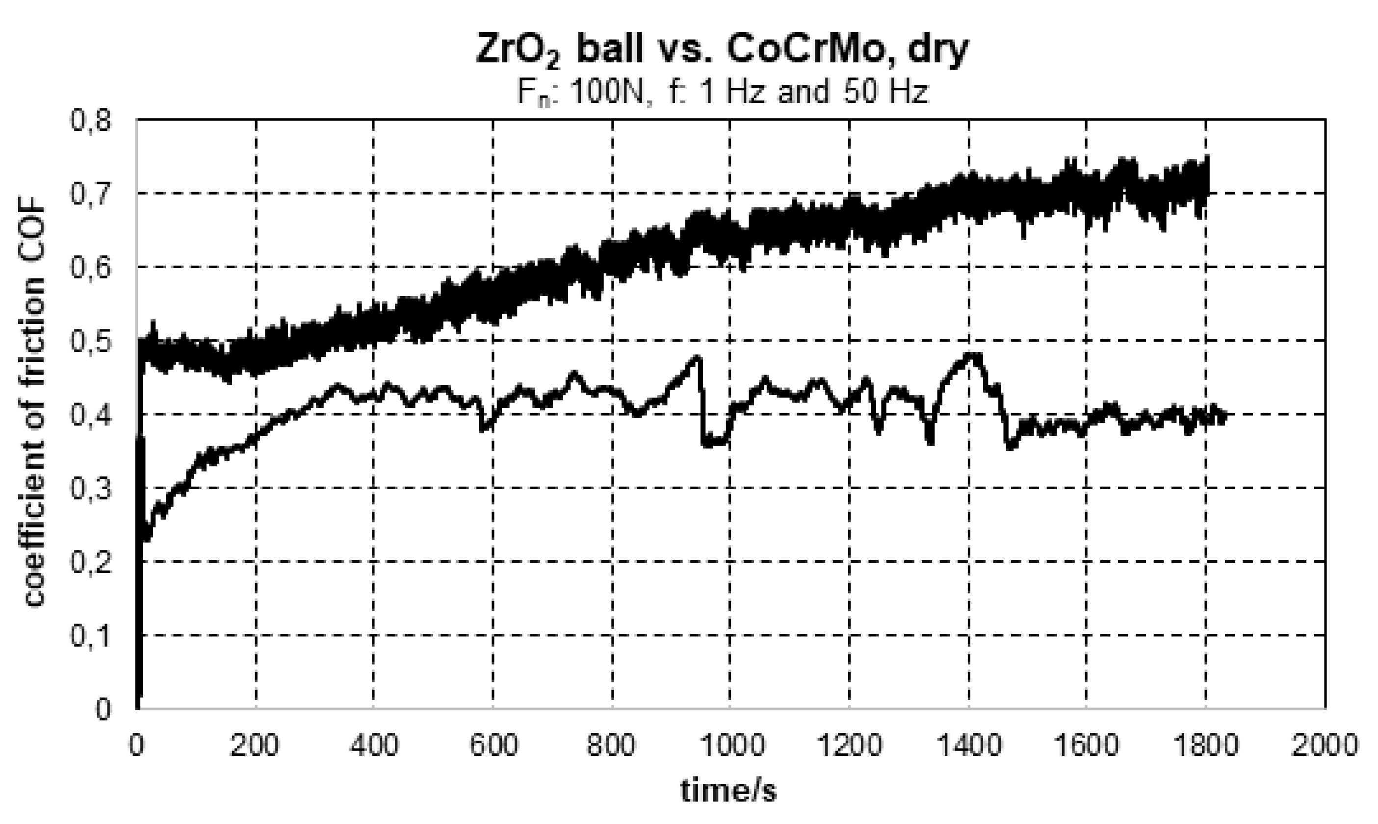
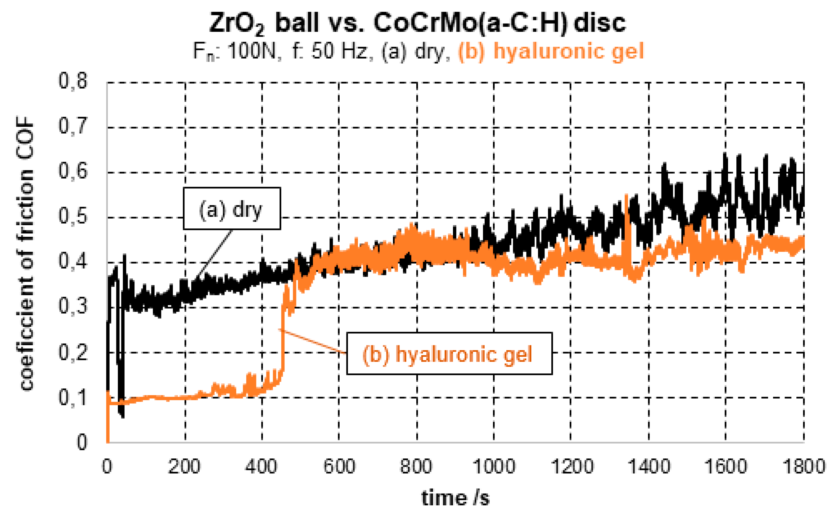
3.1. Coefficient of Friction COF
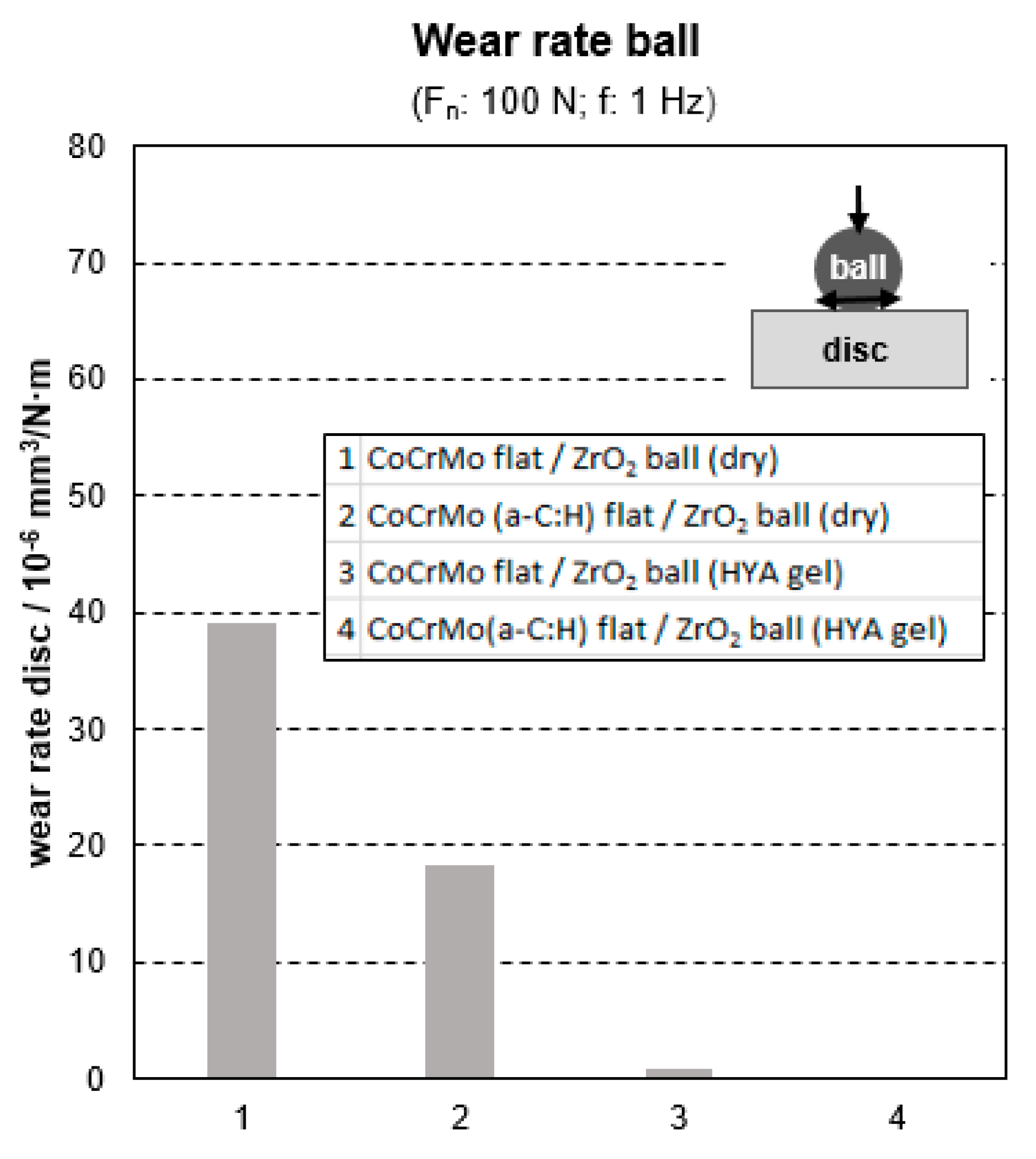
For ZrO2 ball sliding against the medical grade CoCrMo alloy with 1 Hz, the maximum coefficient of friction is 0.482. After an initial increase, COF curve (Figure 5) remains around a certain level, but shows fluctuations and an unsteady characteristic. Increasing the velocity of the sliding movement up to 50 Hz leads to a steady growing COF reaching tremendous COF values higher than 0.7 at the end of the test.
For biomaterials, 50 Hz are excessive loading conditions, while 1 Hz is equal to a fast-moving velocity. The 50 Hz should reflect the overload case of the biomaterial pairing. As seen from Figure 6, the temperature increase is higher for the high frequency loading.
An a-C:H coating on the CoCrMo surface effects a minor reduction of the COF in the extreme overload case of 50 Hz. After 15 min, the COF15 is 0.466 for zirconia sliding against the a-C:H coated CoCrMo under dry conditions (Table 3). It reaches the level of the low frequency case of sliding with ZrO2 ball against the uncoated CoCrMo disc approximately. It amounts to 0.552 at the end of the test. If the hyaluronic gel acts as intermediate lubricant, the COF remains below 0.1 at first (Figure 7, colored curve), but reaches a COF30 of 0.445 and COFmax of 0.549 (Table 3). Under the impact of 100 N normal load but slow movement of 1 Hz, the dry sliding of the ZrO2 ball against the DLC coated CoCrMo is accompanied by an initial tremendous increase of COF up to 0.369.
During the slow movement of 1 Hz frequency (1 step per second), the COF decreases and reaches a relatively low level of COF15 0.113 and COF30 0.105. The curve progression for zirconia ball sliding against the a-C:H coated CoCrMo under dry conditions is smooth in comparison to the zirconia/CoCrMo couple without a-C:H carbon coating. However, there are sections with sharp spikes in the COF curve (Figure 8), if zirconia ball slides slowly against the a-C:H coated CoCrMo in dry atmosphere. If hyaluronic gel is applied as an intermediate medium between the CoCrMo(a-C:H) disc and the ZrO2 ball, the initial COF is lowest in this study. A minimum COF of 0.084 was measured, and, COF15 amounts to 0.096 (Table 3). However, after 30 min testing time, the COFs without and with hyaluronic gel lubrication in the sliding contact are similar and slightly above 0.1 at 1 Hz and 100 N normal load (Figure 9). Observing the macroscopic appearance of the tribological system during the sliding test, the impression of drying-out of hyaluronic gel lubricant arose. The smooth and elastic co-movement of the hyaluronic gel droplet, which embedded the wear couple completely before the test (Figure 10), became less with accumulation of test cycle numbers.
Due to the impact of the hyaluronic gel, the run-in phase of zirconia ball sliding against the a-C:H coated CoCrMo is not accompanied by tremendous initial increase of the COF. COFmax reaches 0.137. Following this initial run-in stage, the COF remains below 0.1 with a minimum of 0.081, but increases steadily up to the level of zirconia sliding against DLC coated CoCrMo without hyaluronic gel, having exactly the same COF30 of 0.105 at the end of the wear test (Figure 9).

3.2. Wear Rates

The hyaluronic gel reduces the wear rate of the DLC coated CoCrMo surfaces. If hyaluronic gel is applied as an intermediate medium, the wear rate of the CoCrMo(a-C:H) disc amounts to 0.16 × 10⁻⁶ mm3/N·m (Table 4, Figure 11). By evaluating this wear rate, it is essential to take into consideration the low frequency of 1 Hz as well as the observed reduction in viscosity during the sliding of the zirconia ball. For higher frequency of 50 Hz, the same tendencies like for low frequency sliding at 1 Hz can be observed for the wear rates of the disc (Table 4, Figure 12). The best results, which is the lowest wear rate is achieved for the a-C:H coated CoCrMo disc. However, the frequency influences the intensity of the wear. By applying the higher frequency of 50 Hz, wear rates are increased. In the case of CoCrMo disc with an a-C:H coating and using hyaluronic gel lubrication, the 50 Hz sliding affects an approximately 3-fold higher wear in comparison to the 1 Hz sliding of the ZrO2 ball (Table 4, Figure 13).
The wear of the ZrO2 balls depends on the frequency as well (Table 4, Figure 14, Figure 15 and Figure 16). For 1 Hz frequency, there was no wear of the ZrO2 ball observed. However, for 50 Hz frequency, a 3-fold higher wear of the ceramic ZrO2 ball in comparison to the pairing a-C:H coated disc was measured in hyaluronic gel (Figure 13 and Figure 14). In general, the wear rates of the ceramic ZrO2 balls are lower in comparison to the discs. Only, the ZrO2 ball which slid against the CoCrMo(a-C:H) with 50 Hz und hyaluronic gel lubrication needs to be excluded from this trend.
It is expected that the contact situation affects boundary or mixed lubrication only. The dry sliding of the zirconia ball against the a-C:H coated CoCrMo disc results in a wear rate of a-C:H coated disc of 21.09 × 10⁻⁶ mm3/N·m (Table 4), which is around two orders of magnitude higher in comparison to usage of hyaluronic gel as intermediate medium.

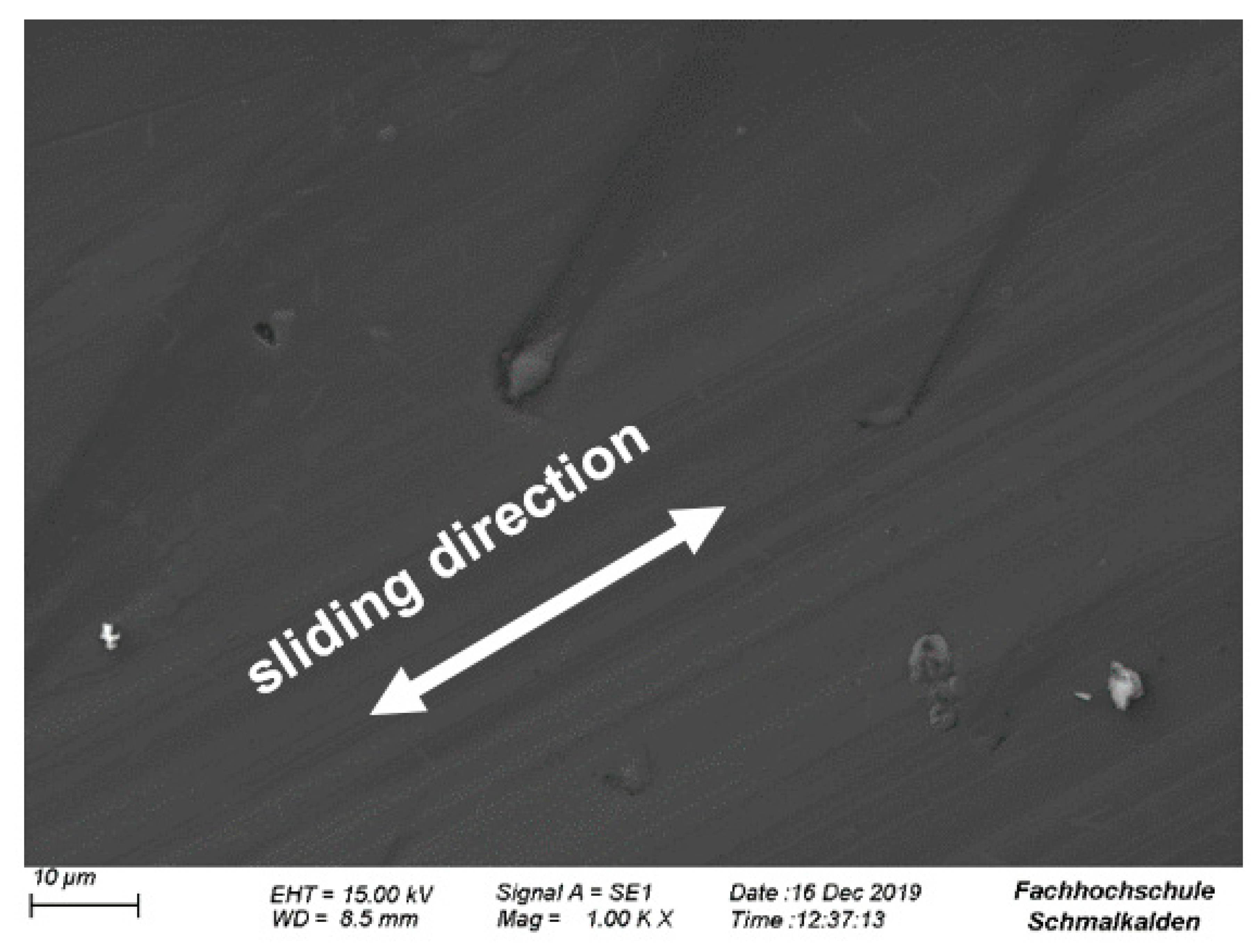
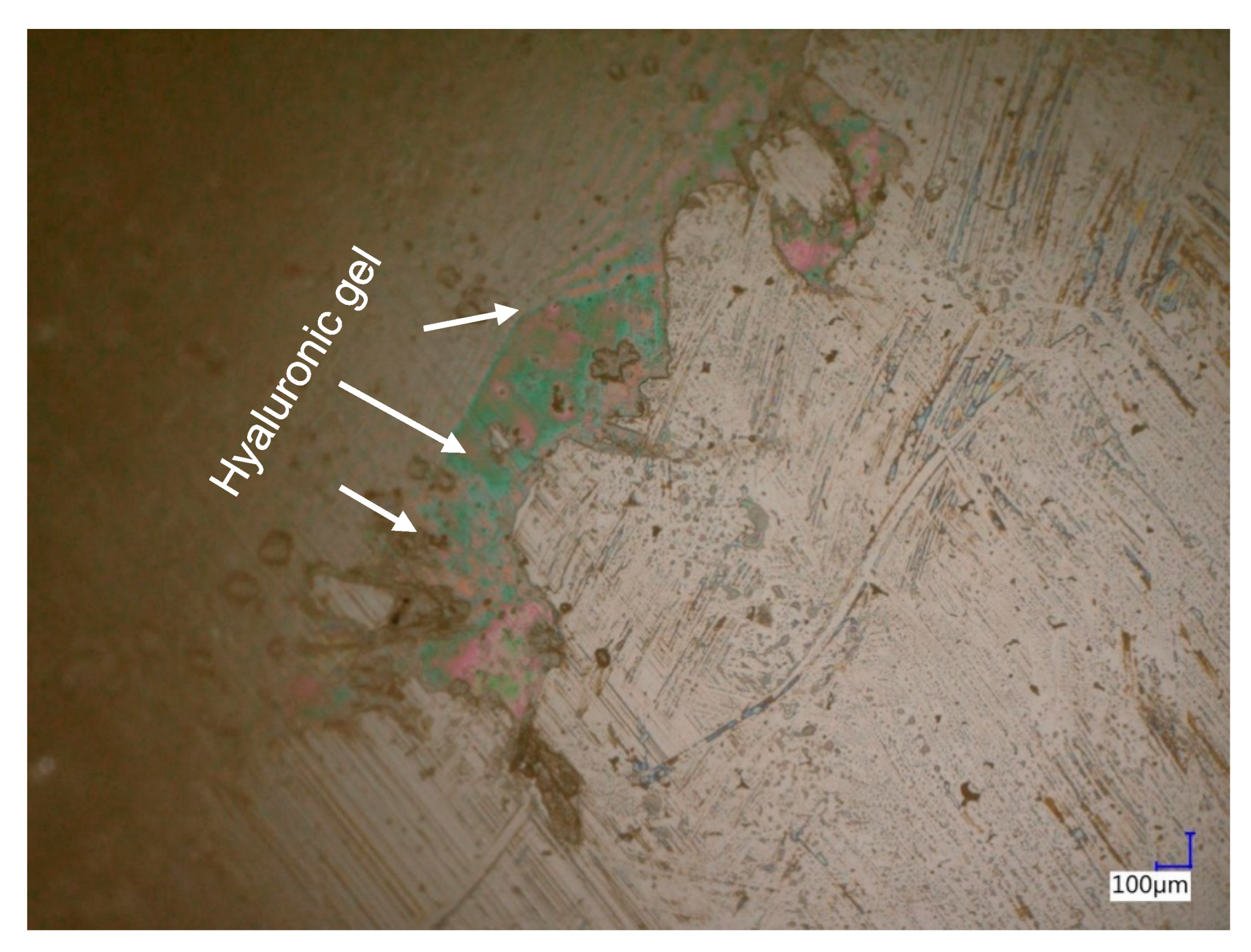
3.3. Microscopic Observations

Figure 17a presents a digital image of the whole wear trace (Figure 17a) after dry sliding of ZrO2 ball against the DLC coated CoCrMo at 1 Hz. Figure 17b presents just the edge of this wear trace. Both photos give evidence of broken out segments within the contact zones. The deepness of the holes is some micrometers (Figure 17b) only, and with this value in the dimension of the DLC coating thickness.
SEM observations (Figure 18) show wrinkled and cracked a-C:H section nearby completely de-adhered a-C:H regions with exposed CoCrMo substrate surface. The metallic substrate obtains deep, but small and sharp grooves. They are not caused by the slow sliding movement of the ZrO2 ball, but seem to be effected by small and sharp segments of broken-out DLC fragments, which are now missing. The ductile CoCrMo seems to be plastic deformed by formerly pressed in a-C:H fragments. The a-C:H was not worn through, but cracked and broke out, as observed by SEM and digital microscopy (Figure 17 and Figure 18). Looking at the remaining a-C:H coating, there is extensive cohesive failure too with cracking and shell-like breakouts. It strengthens the impression, that during the high normal load of 100 N, the metallic CoCrMo substrate did not provide a sufficient support effect, but it was cyclic plastic deformed and forced the stiff inorganic carbon coating with considerably lower plastic deformability to crack.
The hyaluronic gel seems to buffer the insufficient supporting effect of the substrate. Although, the same normal force and frequency were applied, the a-C:H coating remains adhering. The wear trace just shows shearing of the a-C:H coating and minor wear grooves within the a-C:H which is good visible in the black and white digital image (Figure 19a). The colored digital image points to the fact, that there is a trace in the a-C:H visible due to the oriented grooves along the sliding direction. However, the highness level is similar to the roughness of the a-C:H surface. The SEM images show huge plastic deformed grooves for the CoCrMo substrate (Figure 20) and minor grooves within the a-C:H (Figure 21) after a sliding of the ZrO2 ball with 1 Hz. It points to the fact, that the present a-C:H coating can be remodeled and deformed to a certain extent without breaking and cracking. The extent of damage tolerant behavior of different diamond-like carbon coatings depend on several nanostructural features, like hydrogen-content and bonding, C-C-arrangement into aromatic rings or chains, C-C network density, or number and size of spaces in the amorphous carbon network. Other extraordinary influences are the extent of residual stresses, which depend on the ion energy [11] during film deposition as well as degree of ionization and other deposition parameters. As known, the ionization potential of different gaseous precursors for a-C:H generation [15] is different. Benzene has a low ionization potential of about 9 eV only. In comparison to methane or ethane as precursor gases, it gives dense films due to a low H content of the precursor molecules, which effect a lower content of H in the resulting a-C:H films.
The optical evaluation of the wear traces of zirconia balls are necessary for the calculation of the wear rate. In addition, the microscopic appearance of the circle-like wear traces in the zirconia balls gives insight into the wear phenomena. On the zirconia ball metallic transfer from the CoCrMo surface is seen, if sliding without DLC coating (Figure 22 and Figure 23) and/or at high frequency of 50 Hz occurred.
The a-C:H acts as a solid lubricant, but also is hard and wear resistant. No sign of material transfer from the disc was detected on the ZrO2 balls (Figure 24 and Figure 25). The zirconia ball was scratched along the sliding direction. Finally, if there is hyaluronic gel as liquid lubricant between the zirconia ball and the diamond-like carbon coated CoCrMo, no wear trace was found at the ZrO2 balls surface after 1 Hz sliding (Figure 26 and Figure 27).

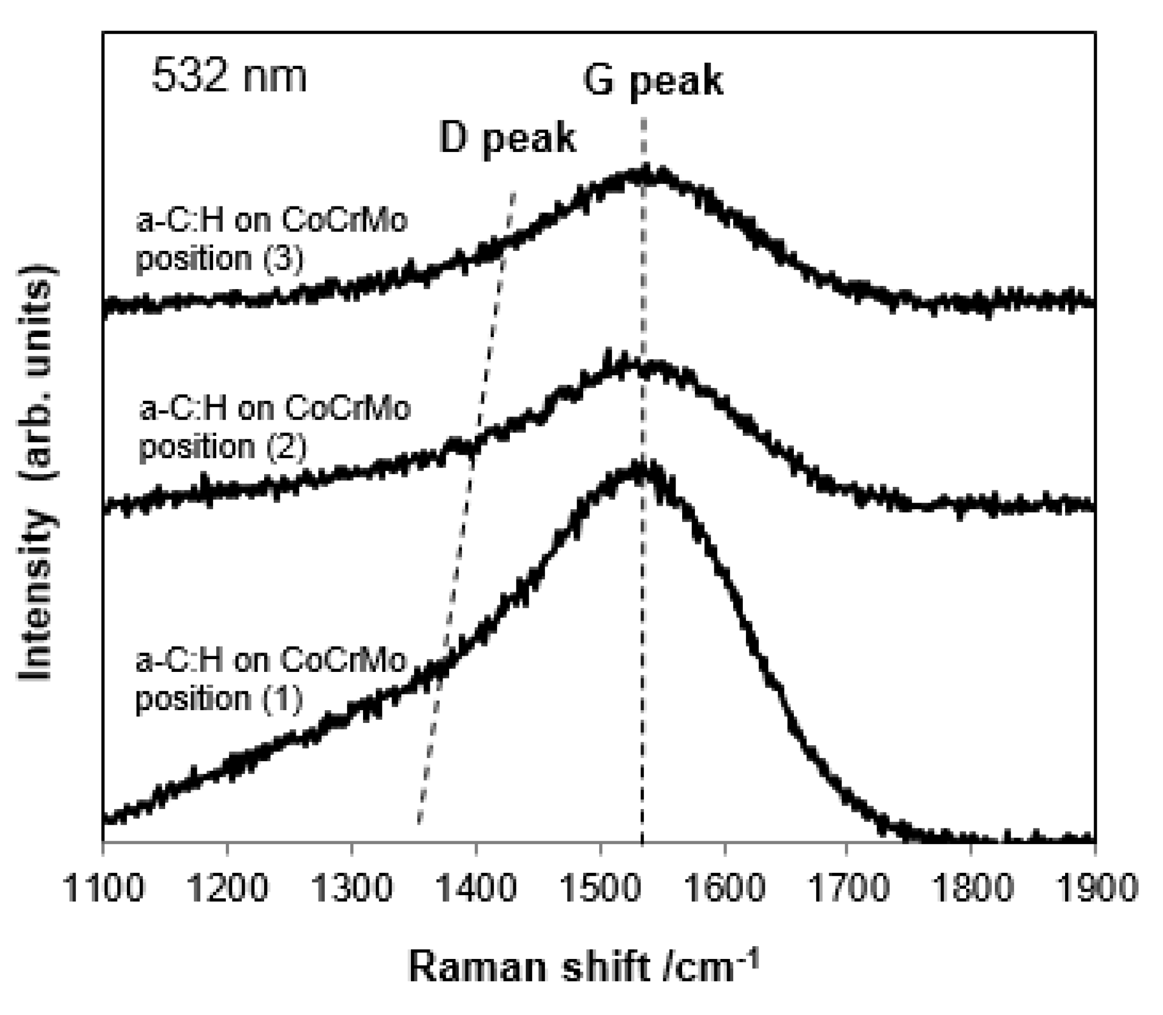
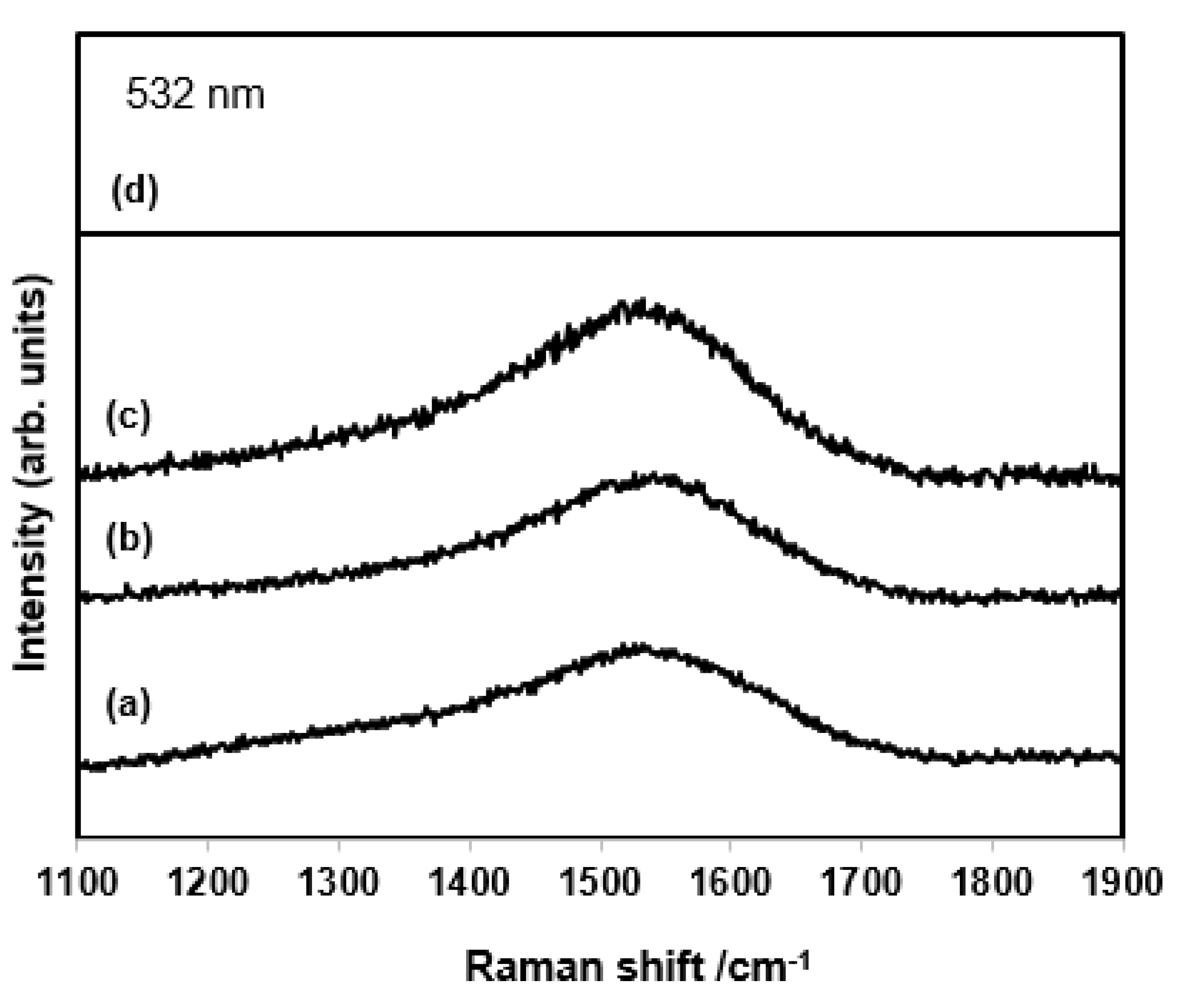
3.4. Raman Spectroscopy
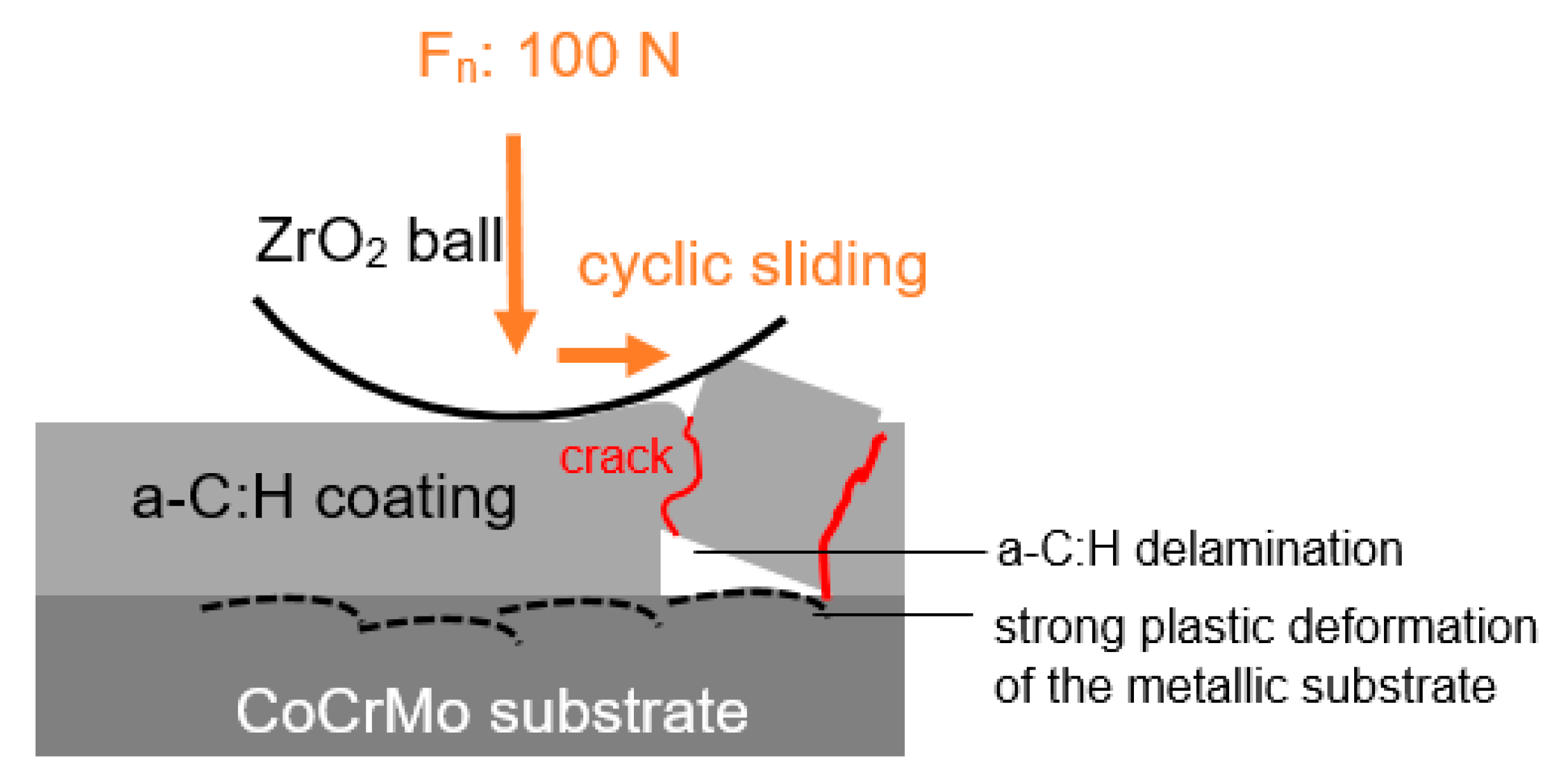
The Raman spectroscopic investigation on different positions on the surface of the diamond-like carbon coated CoCrMo confirm a stable position of the G-peak around 1542 cm−1. However, very different position of the D-peaks were obtained (Table 5; Figure 28). There is an upshifted D-peak position to higher wavenumbers in comparison to typical values for hydrogenated DLC (Figure 28). In addition, the ID/IG ratios are declining, while the ID/IG ratio decreases from 0.48 to 0.20 for the measurement with the most significant D-peak upshifting. Table 5 summarizes the measurement results from Raman spectroscopy on a-C:H coated medical grade CoCrMo before tribological loading.
Raman spectroscopy in the wear trace of a-C:H coated CoCrMo after dry sliding reveal no significant graphitization. The cracked and coherent failed a-C:H sections have almost the same G peak and D peak positions as the a-C:H before wear testing (Figure 29, Table 6). A minor shift of the G peak to higher wavenumbers like 1549.54 cm−1 (groove within the wear trace), 1547.33 cm−1 (crack within the wear trace), and 1545.22 cm−1 can be seen. The ID/IG ratio is lowest within the a-C:H after coherent failure (Figure 21 and Figure 30c). In this case, ID/IG ratio is 0.22, but remains in the same range as the values measured on “as deposited” a-C:H before the wear tests, which scattered a lot (Table 5). For the wear couple ZrO2 ball and a-C:H coated CoCrMo with hyaluronic gel as a lubricant, no change of the a-C:H microstructure were detected by Raman spectroscopy in this study also.

4. Discussion

The movement of human joints, like hip or knee joints, is performed with moderate frequencies of about 1 Hz or lower. Furthermore, human joints are resting a lot. Situations with a start–stop algorithm are often. It is of eminent importance, that a low friction regime is ensured in the early stages of the relative movements between the two counterparts of the artificial joint. Therefore, a homogenous and enduring lubrication is essential. In the present study, the 1 Hz movement of the zirconia ball against the a-C:H coated CoCrMo is possible with a low coefficient of friction. The COF is around 0.1, but the initial run-in state from zero movement shows a high COF of 0.369 in dry environment. However, the natural movement habit of a human is characterized by plenty of start–stop cycles with such run-in situations. One can expect summation of high COF from such the run-in situations, and higher wear rates. Furthermore, during the sliding of the zirconia ball against the a-C:H coated CoCrMo with 1 Hz low frequency, there are sudden increases of the COF (Figure 10), which could be caused by switching between the static and the dynamic COF during the low speed movement on the medical grade surface. In addition, the tribology of a-C:H coatings is complex. There is the formation of a transfer film, which thickness and composition depend on different features. It is known that hydrogenated a-C:H develops its special low friction capacity under sufficient sliding. The later will stimulate the formation of a transfer film, which consists of carbon and hydrogen from the a-C:H structure. Scharf and Singer [16] report about the formation of a transfer film on hydrogenated a-C:H coatings at a low sliding speed of 1 mm/s. They measure changes in the transfer films thickness and accompanied fluctuations of COF from very low values of 0.05 to 0.5 in dry conditions (RH 3–4%). With the evolution of the transfer film, Scharf and Singer [16] observed an overlapping of the Raman signals from the hosting a-C:H coating and the transfer film, which resulted in a common G peak and an upshift of it. They declare that the COF remains in steady state until the transfer film thickness was less than 23–32 nm ± 13 nm. The change in transfer film thickness is possibly influenced by both, low sliding speed, and low humidity. Is the sliding minor, transfer film generation is moderate only. On the contrary, too high sliding speed would stimulate more heat and a certain thinning due to oxidation in air. With the selected 1 Hz and 50 Hz movement, these two extreme conditions are included.
For transfer film composition, the hydrogen evolution from the a-C:H needs to be considered. Hydrogen is set free during proper sliding from the a-C:H. It would be forced to a higher extent, if the sliding increases. Hydrogen satisfies the carbon bonds and stabilizes the transfer film structure and thickness.
Moving zirconia ceramic against a-C:H with higher sliding speeds than 1 Hz in dry atmosphere results in an impressing low COF. Wäsche and Klaffke et al. [17] measured COF of around 0.05 in dry air, and higher COF but still below 0.1 in normal and moist air. They report that no running in with a dangerous high initial COF occurred. Hydrogenated DLC is able to release the hydrogen during proper sliding. Initially, after a-C:H coating deposition, the hydrogen atoms are trapped in the a-C:H structure due to the plasma decomposition and excitation of the gaseous carbon–hydrogen precursor. There are atoms, charged ions, electrons, and neutral species and particle clusters in the Cx-Hy plasma, which were forced with a certain energy to bombard the substrate. Hydrogen atoms can be included and trapped in holes of the diamond-like carbon network. Also, they can form bonds to sp2- or sp3-hybridized carbon atoms. At first, during the initial sliding a kind of shearing of the structure of the loaded top section of a-C:H coating was observed in the present study. During this process, the atomic hydrogen will be stimulated and released. As mentioned before, it can contribute to the formation of a transfer layer. The importance of such hydrogen rearrangement in the a-C:H transfer films during sliding is described in detail by several research groups [18,19]. The tribochemical reaction of hydrogen with activated carbon, in which activation occurs due to the energy accumulation during sliding, leads to the formation of polymeric C-H chains in the transfer films. The ongoing sliding process affects an orientation of the C-H chains parallel to the sliding direction. Easy sliding with low COF is based on the low bonds between the aligned C-H chains in this transfer film which allow easy slip off between the C-H chains. By Raman spectroscopy, in the present study no graphitization of the a-C:H was detected in the wear traces. Raman spectra of a-C:H after the sliding of the ZrO2 ball reveal minor changes only, but a small upshift of the G peak to higher wavenumbers. The degree of graphitization remains apparently low, but the before mentioned shearing were observed by SEM (Figure 21). Apparently, sliding under the chosen parameters (Fn: 100 N; f: 1 Hz) affects shearing the a-C:H top surface mainly with no significant change in a-C:H structure as confirmed by Raman spectroscopy (Figure 29). A schematic visualizes this process (Figure 31).
At the edges of the wear trace after dry sliding of ZrO2 ball against a-C:H coating on CoCrMo, the shearing of the a-C:H is shown by SEM as well (Figure 21). The most striking difference to the hyaluronic gel lubrication of ZrO2 against the hydrogenated amorphous carbon coating is the occurrence of a-C:H ablation under dry conditions. Apparently, changed load transfer into the a-C:H coated CoCrMo disc and temperature rises in the tribo zones effect damage. There is cracking and coating delamination in the center of the wear trace observable by SEM and digital microscopy (Figure 17 and Figure 18) and Raman spectroscopy (Figure 29d and Figure 30d, Table 6). Due to the cyclic sliding and the drastic differences in mechanical properties—such as Young’s modulus, elastic limit and elongation of metallic CoCrMo, and the inorganic diamond-like carbon coating—the extensive plastic deformation of the metallic substrate under high normal loads of 100 N start to throw off coating slices (Figure 32). This may be not occurring during lower normal loads, but in the present study extreme conditions—such as jumping of the patient with an a-C:H coated implant or maybe a wrong positioning of the implant—are considered.
A lubrication with hyaluronic gel results in a smooth and regular COF curve at 1 Hz movement. The COF is below 0.08 and no run-in stage with an initial very high COF is occurring (Figure 8 and Figure 9). On the surface of the hydrogenated DLC, material shearing and minor scratching can be observed (Figure 21). Nevertheless, the wear rate of 0.16 × 10⁻⁶ mm3/Nm for the disc a-C:H coated CoCrMo remains about two orders of magnitude lower in comparison to dry sliding of zirconia against a-C:H with a wear rate of the disc of 21.09 × 10⁻⁶ mm3/Nm. It underlines the fact that lubrication plays an essential role in durability of diamond-like carbon and the ability to unfold its performance and unique properties in biomedical joints. It is known to reduce shock, vibration surface fatigue, and changes the load transfer into the base body of the tribological system. A cooling of the tribological system can be expected. This is advantageous for a-C:H as well, because diamond-like carbons endure moderate temperature rise only.
The increase in COF of the hyaluronic gel lubricated zirconia sliding against the a-C:H surface of the CoCrMo may be attributed to the observed change of viscosity of hyaluronic gel. Its COF30 reaches the level of non-lubricated a-C:H at 1 Hz sliding. It may be attributed to a reduction in the lubricating effect. The lubrication conditions seem to be in the region of mixed or boundary lubrication only. Otherwise, no scratching or shearing would occur at the a-C:H surface. In the boundary mode lubrication of cartilage-cartilage, the relative effectiveness of friction reduction has been shown to be dependent on the molecular weight of hyaluronic acid with higher molecular weight resulting in lower friction [20,21]. Bonnevie et al. [22] showed that the lubricating effect of hyaluronic acids with different viscosities widely varies with no correlation to the frictional behavior. They argue that for highly viscous polymeric solutions like studied hyaluronic acids wall slip and interfacial effects need additional consideration and can alter the lubrication drastically. Friction coefficients of the real biomedical counterparts as measured in this study give a better correlation to the wear behavior.
The solid–solid contact between ceramic ZrO2 ball and metallic CoCrMo alloy without a-C:H coating and hyaluronic gel lubrication is leading to a tremendous wear rate of both ball and metallic alloy. Applying 1 Hz for 30 min results in a wear rate of the disc of 67.01 × 10⁻⁶ mm3/N·m, while 50 Hz for results in a wear rate of 77.37 × 10⁻⁶ mm3/N·m for the disc. Increasing the frequency worsens the situation and material loss by strong adhesive and abrasive wear, as expected. Surprisingly, the wear rate of the ZrO2 ball was lower at higher frequency with a value of 13.19 × 10⁻⁶ mm3/N·m in comparison to the 1 Hz sliding with a 3-fold higher ZrO2 balls wear rate of 39.13 × 10⁻⁶ mm3/N·m. It was observed by microscopic methods in this study, that during 50 Hz sliding, smearing, adhesive wear of CoCrMo after a coating failure are dominating the wear process, while the ceramic ball remains less damaged.
If the ZrO2 ball slides against the a-C:H coated medical grade CoCrMo with 1 Hz and 100 N normal force, the lowest wear rate with 0.16 × 10⁻⁶ mm3/N·m were reached with hyaluronic gel lubrication. Although, an extreme high normal load was applied and unusual low sliding speed of 1 Hz were chosen, the a-C:H carried the load and was not worn through, nor delaminated. The ZrO2 ball showed no sign of wear at all (Figure 26 and Figure 27), if lubrication with hyaluronic gel was applied. The hyaluronic gel wetting was excellent. After the tests, it was hard to remove the dried hyaluronic residuals from the ball and the disc.
The 50 Hz sliding with 100 N normal load is an even more drastic loading of the biomedical materials. However, also in this extreme situation, the a-C:H coating reduced the wear rate and ensure a certain time low COF of about 0.1 (Figure 7), if the hyaluronic gel lubrication can be ensured. Due to the high frequency loading, a temperature increase in the tribological contact zone can contribute to the failure of a-C:H in this case additionally. Care needs to be taken to design a biomedical implant, which enables sufficient thermal conductivity for both, the stability of a-C:H coating and the prevention of quality of the hyaluronic gel as well as enduring lubrication.

5. Conclusions

An a-C:H coating can be useful for preventing metallic ions and particle loosening from CoCrMo alloys. The undesired migration of metallic ions and particles in the body is associated with tissue reaction as well as body liquids and protein interactions. A durable coating ensures long-term protection. As shown in this study, in cases of occasional overloading or ongoing start–stop movements, the COF can suddenly increase, if no homogenous lubrication is ensured. Hyaluronic gel lubrication provides an excellent protection against occasional overloading of biomedical materials during extreme movement or implant de-arrangement. In order to ensure homogeneous lubrication during the life span of the implant, measures need to be implemented for continuous supply of hyaluronic lubricant. Such measures can include proper macroscopic design of the implants and/or micropatterning of the surface. Furthermore, to prevent coating delamination in cases of occasional overloading or ongoing start–stop movements with initial high COF during the run-in stage, adherence of the coating should be improved by different measures. There are manifold options to reach improved coating stability in addition to mere graded a-C:H microstructures. Supporting interlayers—such as TiC, TiAlC, TiAlN, TiAlC, and SiNx interlayer—are state of the art or state of research [23,24,25,26] for several applications. The long-term effect of any interlayer in biomedical environment and other changes on the tribological system need to be verified.

Author Contributions

C.S.: PE-CVD deposition of a-C:H coatings; S.S.: Microscopic investigations; A.D.-R.: Raman spectroscopy and wear tests. All authors have read and agreed to the published version of the manuscript.

Funding

The support for the Article Processing Charge by the Thuringian Ministry for Economic Affairs, Science and Digital Society is acknowledged. In addition, authors are grateful for the financial support of the project BUNT 2015-0012 “Biogenic different nanostructured high performance carbons” which enabled Raman spectroscopy. Furthermore, the authors thank the Arbeitsgemeinschaft industrieller Forschungsvereinigungen AiF “Otto von Guericke” e.V. for financial funding of the project IGF015/03 and the Deutsche Forschungsgemeinschaft DFG for financial support of the project DO 660-1.

Conflicts of Interest

The authors declare no conflict of interest.

References

  1. Kung, M.S.; Markantonis, J.; Nelson, S.D.; Campbell, P. The synovial lining and synovial fluid properties after joint arthroplasty. Lubricants 2015, 3, 394–412. [Google Scholar] [CrossRef] [Green Version]
  2. Posada, O.M.; Tate, R.J.; Meek, D.; Grant, M.H. In vitro analysis of toxicity, immunological, and gene expression effects of cobalt-chromium-alloy wear debries and Co ions derived from metal-on-metal hip implants. Lubricants 2015, 3, 539–568. [Google Scholar] [CrossRef] [Green Version]
  3. Fuhrer, E.; Bäcker, A.; Kraft, S.; Gruhl, F.J.; Kirsch, M.; MacKinnin, N.; Korvik, J.G.; Sharma, S. 3D Carbon Scaffolds for Neural Stem cell culture and magnetic resonance imaging. Adv. Healthc. Mater. 2018, 7, 1–7. [Google Scholar] [CrossRef] [Green Version]
  4. Patel, A.; Mukundan, S.; Wenhu, W.; Karumuri, A.; Sant, V.; Mukhopadhyay, S.M.; Sant, S. Carbon-based hierarchical scaffolds for myoblast differentiation: Synergy between nano-functionalization and alignment. Acta Biomater. 2016, 32, 77–88. [Google Scholar] [CrossRef] [PubMed] [Green Version]
  5. Eivazzadeh-Keihan, R.; Maleki, A.; de la Guardia, M.; Bani, M.S.; Chenab, K.K.; Pashazadeh-Panahi, P.; Baradaran, B.; Mokhtarzadeh, A.; Hamblin, M.R. Carbon based nanomaterials for tissue engineering of bone: Buidling new bone on small black scaffolds: A review. J. Adv. Res. 2019, 18, 185–201. [Google Scholar] [CrossRef] [PubMed]
  6. Stankova, L.; Musilkova, J.; Broz, A.; Potocky, S.; Kromka, A.; Kozak, H.; Izak, T.; Artemenko, A.; Stransa, D.; Barcakova, L. Alteration to the adhesion, growth and osteogenetic differentiation of human osteoblast-like cells on nanofibrous polylactide scaffolds with diamond nanoparticles. Diam. Relat. Mater. 2019, 97, 107421–107426. [Google Scholar] [CrossRef]
  7. Ngu-Schwemlein, M.; Chin, S.F.; Hileman, R.; Drozdowski, C.; Upchurch, C.; Hargrove, A. Carbon nanodots as molecular scaffolds for development of antimicrobial agents. Bioorg. Med. Chem. Lett. 2016, 26, 1745–1749. [Google Scholar] [CrossRef] [Green Version]
  8. Xue, J.L.; Wu, B.J.; Zhang, T.F.; Leng, Y.X.; Huang, N. Tribocorrosion behaviour of DLC-coated CoCrMo alloy in simulated biological environment. Vacuum 2013, 92, 39–42. [Google Scholar] [CrossRef]
  9. Xiang, D.D.; Sui, X.D.; Ran, X.P.; Hao, J.Y.; Wang, Z.W.; Liao, Z.H.; Liu, W.Q.; Tor, S.B. Improving biotribological properties and corrosion resistance of CoCrMo alloy via a Cr-GLC nanocomposistes film in simulated body fluids. Surf. Coat. Technol. 2019, 378, 124840. [Google Scholar] [CrossRef]
  10. Dorner-Reisel, A.; Schuerer, C.; Müller, E. The wear resistance of diamond-like carbon coated and uncoated Co28Cr6Mo knee prostheses. Diam. Relat. Mater. 2004, 13, 823–827. [Google Scholar] [CrossRef]
  11. Dorner-Reisel, A.; Gärtner, G.; Reisel, G.; Irmer, G. Diamond-like carbon films for polyethylene femoral parts: Raman and FT-IR spectroscopy before and after incubation in simulated body liquid. Anal. Bioanal. Chem. 2008, 390, 1487–1493. [Google Scholar] [CrossRef] [PubMed]
  12. Tanaka, Y.; Nakamura, S.; Kuriyamma, S.; Nishitani, K.; Ito, H.; Fufu, M.; Watanabe, M.; Matsuda, S. Medical tilting of the joint line in posterior stabilized total knee arthroplasty increases contact force and stress. Clin. Biomech. 2019, 53, 54–59. [Google Scholar] [CrossRef] [PubMed] [Green Version]
  13. Valenzuela, K.A.; Zhang, S.; Schroeder, L.E.; Weinhardt, J.-T.; Cates, H.E. Increased knee loading in stair ambulation in patients dissatisfied with their total knee replacement. Clin. Biomech. 2019, 67, 38–44. [Google Scholar] [CrossRef] [PubMed]
  14. Erceg, M. The influence of femoral head shift on hip biomechanics: Additional parameters accounted. Intern. Orthop. 2009, 33, 95–100. [Google Scholar] [CrossRef] [Green Version]
  15. Robertson, J. Classification of Diamond-like Carbon. In Tribology of Diamond-Like Carbon Films, 1st ed.; Donnet, C., Erdemir, A., Eds.; Springer Science: New York, NY, USA, 2008; pp. 13–24. [Google Scholar]
  16. Scharf, T.W.; Singer, I.L. Third Bodies and Tribochemistry of DLC Coatings. In Tribology of Diamond-Like Carbon Films, 1st ed.; Donnet, C., Erdemir, A., Eds.; Springer Science: New York, NY, USA, 2008; pp. 201–236. [Google Scholar]
  17. Wäsche, R.; Klaffke, D. Tribology of DLC Films Under Fretting Conditions, 1st ed.; Donnet, C., Erdemir, A., Eds.; Springer Science: New York, NY, USA, 2008; pp. 362–382. [Google Scholar]
  18. Sugimoto, I.; Miyake, S. Oriented hydrocarbons transferred from a high performance lubricative amorphous C:H:Si films during sliding in a vacuum. Appl. Phys. Lett. 1990, 56, 1868–1870. [Google Scholar] [CrossRef]
  19. Fontaine, J.; Donnet, C.; Grill, A.; Le Mogne, T. Tribochemistry between hydrogen and diamond-like carbon films. Surf. Coat. Technol. 2001, 146, 286–291. [Google Scholar] [CrossRef]
  20. Kwiecinski, J.J.; Dorosz, S.G.; Ludwig, T.E. The effect of molecular weight on hyaluronan’s cartilage boundary lubricating ability-alone nd in combination with proteoglycan. Ostheoarthritis Cartil. 2011, 19, 1356–1362. [Google Scholar] [CrossRef] [Green Version]
  21. Crowman, M.K.; Schmidt, T.A.; Raghavan, P.; Stecco, A. Viscoelastic properties of hyaluronan in physiological conditions. F1000Research 2015, 4, 622–635. [Google Scholar] [CrossRef] [Green Version]
  22. Bonnevie, E.D.; Galesso, D.; Secchieri, C.; Bonassar, L.J. Frictional characterization of injectable hyalurinc acids is more predictive of clinical outcomes than traditional rheological or viscoelastic characterization. PLoS ONE 2019, 14, e02216702. [Google Scholar] [CrossRef]
  23. Schürer, C.; Semmler, U. Advanced Applications of Diamond-like Carbon Coatings, Lecture at EUROMAT 1999 on Sept 28th 1999 in Munich, GERMANY.
  24. Wu, Y.M.; Liu, J.Q.; Cao, h.T.; Wu, Z.Y.; Wang, Q.; Ma, Y.P.; Jiang, H.; Wen, F.; Pei, Y.T. On the adhesion of DLC films deposited on nitrile butadiene rubber: A Ti-C interlayer. Diam. Relat. Mater. 2020, 101, 107563. [Google Scholar] [CrossRef]
  25. Chen, Q.; Zheng, C.; Xu, H.; Lv, H.; Wang, Z.; Wang, X. Effect of SiNx interlayer thickness on adhesion and friction properties of diamond-like carbon films. Diam. Relat. Mater. 2019, 94, 186–193. [Google Scholar] [CrossRef]
  26. Kang, S.; Lim, H.-P.; Lee, K. Effects of TiCN interlayer on bonding characteristics and mechanical properties of DLC-coated Ti-6Al-4V ELI alloy. Intern. J. Refract. Met. Hard Mat. 2015, 53A, 13–16. [Google Scholar] [CrossRef]
Figure 1. Schematic of the set-up for a-C:H deposition by direct current discharge.
Lubricants 08 00035 g001
Figure 2. Sliding ZrO2 ball moves across CoCrMo sample with 1 Hz.
Lubricants 08 00035 g002
Figure 3. Schematic of the test set up: (a) without hyaluronic gel (dry); (b) with hyaluronic gel Fn: normal load; s: sliding distance (stroke).
Lubricants 08 00035 g003
Figure 4. Schematic of the wear trace in the disc with (a) the diameters d3 and d4, (b) Wq,disc.
Lubricants 08 00035 g004
Figure 5. Coefficient of friction COF during the dry sliding of ZrO2 ball against uncoated CoCrMo with 50 Hz or 1 Hz (Fn: 100 N).
Lubricants 08 00035 g005
Figure 6. Temperature change during the dry sliding of ZrO2 ball against uncoated CoCrMo with 50 Hz or 1 Hz (Fn: 100 N).
Lubricants 08 00035 g006
Figure 7. Coefficient of friction COF during the sliding of ZrO2 ball against a-C:H coated CoCrMo without and with hyaluronic gel lubrication (Fn: 100 N, f: 50 Hz).
Lubricants 08 00035 g007
Figure 8. Coefficient of friction COF during the sliding of ZrO2 ball against a-C:H coated CoCrMo without and with hyaluronic gel lubrication (Fn: 100 N, f: 1 Hz).
Lubricants 08 00035 g008
Figure 9. Section with sharp spikes sections in COF curve without hyaluronic gel lubrication (a), smooth COF curve with hyaluronic gel lubrication (b) during sliding of ZrO2 ball against CoCrMo(a-C:H) (Fn: 100 N, f: 1 Hz).
Lubricants 08 00035 g009
Figure 10. ZrO2 ball wetted with hyaluronic gel before the wear test of a-C:H coated CoCrMo sample with 1 Hz.
Lubricants 08 00035 g010
Figure 11. Wear of uncoated and a-C:H coated discs at 1 Hz frequency (dry or with hyaluronic gel lubrication).
Lubricants 08 00035 g011
Figure 12. Wear of uncoated and a-C:H coated discs at 50 Hz frequency (dry or with hyaluronic gel lubrication).
Lubricants 08 00035 g012
Figure 13. Wear of a-C:H coated discs at different frequencies.
Lubricants 08 00035 g013
Figure 14. Wear of ZrO2 balls sliding against a-C:H coated discs at different frequencies.
Lubricants 08 00035 g014
Figure 15. Wear of ZrO2 balls at 1 Hz frequency (dry or with hyaluronic gel lubrication).
Lubricants 08 00035 g015
Figure 16. Wear of ZrO2 balls at 50 Hz frequency (dry or with hyaluronic gel lubrication).
Lubricants 08 00035 g016
Figure 17. Wear trace after sliding of ZrO2 ball against a-C:H coated CoCrMo without hyaluronic gel lubrication (dry, Fn: 100 N, f: 1 Hz); (a) overview of the wear trace; (b) edge of the wear trace.
Lubricants 08 00035 g017aLubricants 08 00035 g017b
Figure 18. Wear trace with wrinkled hydrogenated a-C:H and coating deadherence after dry sliding of ZrO2 ball against the CoCrMo(a-C:H) disc (Fn: 100 N, f: 1 Hz), SEM.
Lubricants 08 00035 g018
Figure 19. Wear trace after sliding of ZrO2 ball against a-C:H coated CoCrMo with hyaluronic gel lubrication (Fn: 100 N, f: 1 Hz); (a) black and white image; (b) color image.
Lubricants 08 00035 g019aLubricants 08 00035 g019b
Figure 20. Wear trace CoCrMo disc without a-C:H coating after dry sliding of ZrO2 ball, (Fn: 100 N, f: 1 Hz), SEM.
Lubricants 08 00035 g020
Figure 21. Wear trace CoCrMo(a-C:H) disc after dry sliding of ZrO2 ball, (Fn: 100 N, f: 1 Hz), SEM.
Lubricants 08 00035 g021
Figure 22. Wear marks on the surface of ZrO2 ball after sliding against the uncoated CoCrMo disc, Fn: 100 N, f: 1 Hz, dry (3D image, digital microscopy).
Lubricants 08 00035 g022
Figure 23. Wear marks on the surface of ZrO2 ball after sliding against the uncoated CoCrMo disc, Fn: 100 N, f: 1 Hz, dry (2D image, digital microscopy).
Lubricants 08 00035 g023
Figure 24. Wear marks on the surface of ZrO2 ball after sliding against the a-C:H-coated CoCrMo disc, Fn: 100 N, f: 1 Hz, dry (3D image, digital microscopy).
Lubricants 08 00035 g024
Figure 25. Wear marks on the surface of ZrO2 ball after sliding against the a-C:H-coated CoCrMo disc, Fn: 100 N, f: 1 Hz, dry (2D image, digital microscopy).
Lubricants 08 00035 g025
Figure 26. Wear marks on the surface of ZrO2 ball after sliding against the a-C:H-coated CoCrMo disc, Fn: 100 N, f: 1 Hz, hyaluronic gel (3D image, digital microscopy).
Lubricants 08 00035 g026
Figure 27. Wear marks on the surface of ZrO2 ball after sliding against the a-C:H-coated CoCrMo disc, Fn: 100 N, f: 1 Hz, hyaluronic gel (2D image, digital microscopy).
Lubricants 08 00035 g027
Figure 28. Raman spectra of a-C:H coatings on CoCrMo (as deposited and before wear tests).
Lubricants 08 00035 g028
Figure 29. Raman spectra of hydrogenated a-C:H coatings on CoCrMo after wear tests w/o hyaluron-gel (Fn: 100 N, f: 1 Hz) (a) groove within the a-C:H wear trace, (b) crack within the a-C:H wear trace, (c) coherent failure within the a-C:H wear trace, (d) CoCrMo substrate after delamination of the coating.
Lubricants 08 00035 g029
Figure 30. Measurement positions for Raman spectroscopy in the wear trace of a-C:H coated CoCrMo after dry sliding of ZrO2 ball (Fn: 100 N, f: 1 Hz). For explanation of (ad) see Figure 29.
Lubricants 08 00035 g030
Figure 31. Shearing of a-C:H at the coatings surface with rearrangement of hydrogen during sliding is essential for transfer film formation.
Lubricants 08 00035 g031
Figure 32. Plastic deformation of the substrate due to cyclic application of high loads and cyclic interfacial cracking with delamination.
Lubricants 08 00035 g032aLubricants 08 00035 g032b
Table 1. Processing parameters for diamond-like carbon coatings deposition
Electric Parameters
Hot cathode heating current UH30–80 A
Discharge current0.1–1 A
Current through substrate holder10–400 mA
Voltage between cathode and anode grid30–300 V
Bias voltage0–3.5 kV
Table 2. Parameters of the wear tests
DiscBallIntermediate MediumNormal Force Fn (N)Frequency (Hz)Time (s)
CoCrMoZrO2dry10011800
CoCrMo(a-C:H)ZrO2dry10011800
CoCrMoZrO2hyaluronic gel10011800
CoCrMo(a-C:H)ZrO2hyaluronic gel10011800
CoCrMoZrO2dry100501800
CoCrMo(a-C:H)ZrO2dry100501800
CoCrMoZrO2hyaluronic gel100501800
CoCrMo(a-C:H)ZrO2hyaluronic gel100501800
dry: without intermediate medium.
Table 3. Coefficients of friction
DiscBallIntermediate Mediumf (Hz)COFmaxCOF15COF30
CoCrMoZrO2dry10.4820.4380.394
CoCrMo(a-C:H)ZrO2dry10.3690.1130.105
CoCrMoZrO2hyaluronic gel10.4010.3080.204
CoCrMo(a-C:H)ZrO2hyaluronic gel10.1370.0960.105
CoCrMoZrO2dry500.7510.6370.724
CoCrMo(a-C:H)ZrO2dry500.6780.4660.552
CoCrMoZrO2hyaluronic gel500.7330.3100.277
CoCrMo(a-C:H)ZrO2hyaluronic gel500.5490.4330.445
COF15: coefficient of friction after 15 min sliding; COF30: coefficient of friction after 30 min sliding; COFmax: maximal coefficient of friction.
Table 4. Wear rates according the standard DIN 51834-3
DiscBallIntermediate Mediumf (Hz)Wq,disc (µm2)Wear Rate Disc (mm3/Nm)Wear Rate Ball (mm3/Nm)
CoCrMoZrO2dry19422.9367.01 × 10−639.13 × 10⁻⁶
CoCrMo(a-C:H)ZrO2dry11231.1121.09 × 10−618.37 × 10⁻⁶
CoCrMoZrO2hyaluronic gel12921.0926.07 × 10−60.893 × 10⁻⁶
CoCrMo(a-C:H)ZrO2hyaluronic gel127.090.16 × 10−6-
CoCrMoZrO2dry50260,716.3677.37 × 10−613.19 × 10⁻⁶
CoCrMo(a-C:H)ZrO2dry50183,843.3227.23 × 10−60.015 × 10⁻⁶
CoCrMoZrO2hyaluronic gel5023,361.032.979 × 10−60.000762 × 10⁻⁶
CoCrMo(a-C:H)ZrO2hyaluronic gel504313.190.57 × 10−61.87 × 10⁻⁶
Table 5. Results from Raman spectroscopy (λ = 532 nm) of a-C:H coated medical grade CoCrMo
a-C:H, as DepositedD Peak Position/cm−1G Peak Position/cm−1ID/IG Ratio
a-C:H, as deposited position (1)1362.301541.290.48
a-C:H, as deposited position (2)1384.071542.120.33
a-C:H, as deposited position (3)1396.561542.560.20
Table 6. Results from Raman spectroscopy (λ = 532 nm) of a-C:H coated medical grade CoCrMo after wear tests (Fn: 100 N; f: 1 Hz; dry)
CoCrMo(a-C:H) after ZrO2 Sliding (100 N; 1 Hz; Dry)D Peak Position/cm−1G Peak Position/cm−1ID/IG Ratio
(a)
groove within the wear trace in a-C:H
1408.811549.540.39
(b)
crack within the wear trace in a-C:H
1412.011547.330.39
(c)
deepening within the a-C:H wear trace (coherent failure)
1396.011545.220.22
(d)
deepening within the wear trace (after coating delamination)
---

