1. Introduction and Research Background
Journal bearings are used in engineering to support moving components and to transfer loads. The most prominent representatives are hydrodynamic bearings in internal combustion engines. These engine bearings are placed within the heart of the engine, thus the crankcase, and support crucial parts such as the crankshaft or connecting rod. The functionality of such bearings relies on two fundamental aspects, viz. sufficient lubrication and design aspects resulting in hydrodynamic film formation as well as suitable bearing materials [
1,
2].
The latter is addressed with unique solutions for specific applications and material selection has been found to be a compromise between contradicting demands such as fatigue strength and tribological properties (i.e., a material needs to be hard and soft at the same time), as well as chemical compliance, to name only a few of many [
3]. To meet these requirements, journal bearings are usually designed with a layered structure and heterogeneous materials [
4,
5,
6]. Each layer and material therein has to fulfil a specific task addressing each contradictory demand. The main layers are defined as steel back for mechanical support, a bearing lining and optional overlay systems.
Over the years, several bearing materials and products have been developed and investigated. Softer materials, such as tin or lead based alloys, are used for low load applications with higher requirements from a tribological perspective, such as sliding capabilities, conformity, etc. [
7]. Additionally, aluminium based alloys with a high content of soft metal content such as tin are used [
8]. For high fatigue applications, harder alloys such as bronze are used. Depending on the specific application, these materials have been generally equipped with lead as soft phase or coated with tribologically suited overlays. Electroplated layers composed of tin or lead as well as harder sputtered layers (e.g., aluminium-tin based) have been commonly used as overlay materials in the past [
9,
10].
In recent years, additional environmental requirements have gained importance. Lead is largely banned as a construction material and new operating conditions were added by means of engine modifications such as downsizing or stop start fuel saving systems. As a result, new developments in bearing design have emerged. Sato et al. [
11] noted beneficial anti-seizure effects of sulphides in bronze lining material as a possible replacement for leaded bronze. Tin based coatings have been found to have equal and or better sliding performance and wear resistance in comparison to lead based coatings [
10,
12]. Recent developments also introduced complex multilayer coatings for bearing applications with advanced tribological properties such as a novel multilayer system composed of tin copper layers and a tin nickel sublayer [
13].
Due to the higher demands for improved fuel economy and tighter environmental legislation, stop start technology is also applied to an increasing number of engines in various applications. Although on the one hand, this new operation condition helps to significantly reduce fuel consumption, on the other hand, it also dramatically increases the amount of boundary and mixed friction lubrication regimes for highly loaded areas of the engine, in particular the bearings. Selected studies have shown that several types of multilayer bearings (such as bearings with sputtered or electroplated coatings) show a high wear rate under stop start conditions and that only polymer coated bearing solutions seem to withstand stop start wear to a greater extent [
14,
15]. In relation to this, Gebretsadik et al. [
16] also noted beneficial friction performance for a MoS
2 based polymer coating compared to other conventional bearing materials such as aluminium bimetal bearings or lead based coatings.
The current research addresses bearing material characterization and tribological performance of bearing materials under stop start conditions. As discussed above, some studies have previously been conducted in this area; however, in particular the performance of engine polymer bearings, especially under stop start running conditions, have been explored to a lesser extent. Hence, this study aims to determine the friction and wear performance of different commercially available polymer bearing (PB) products found in passenger cars and/or heavy duty diesel engines on the market under stop start operating conditions.
2. Bearing Material Characterization
Three bearing materials with spray coated polymer overlays have been investigated and tested. Material characterization has been carried out with the aid of light microscopy (LIMI), scanning electron microscopy (SEM) and elemental analysis (EDX) of the surfaces and micro sections. In doing so, the layer structure and composition of the bearings can be visualized in detail. The micro sections are produced by mechanical polishing, and detailed analysis of the coatings is achieved by using the ion slicer technique.
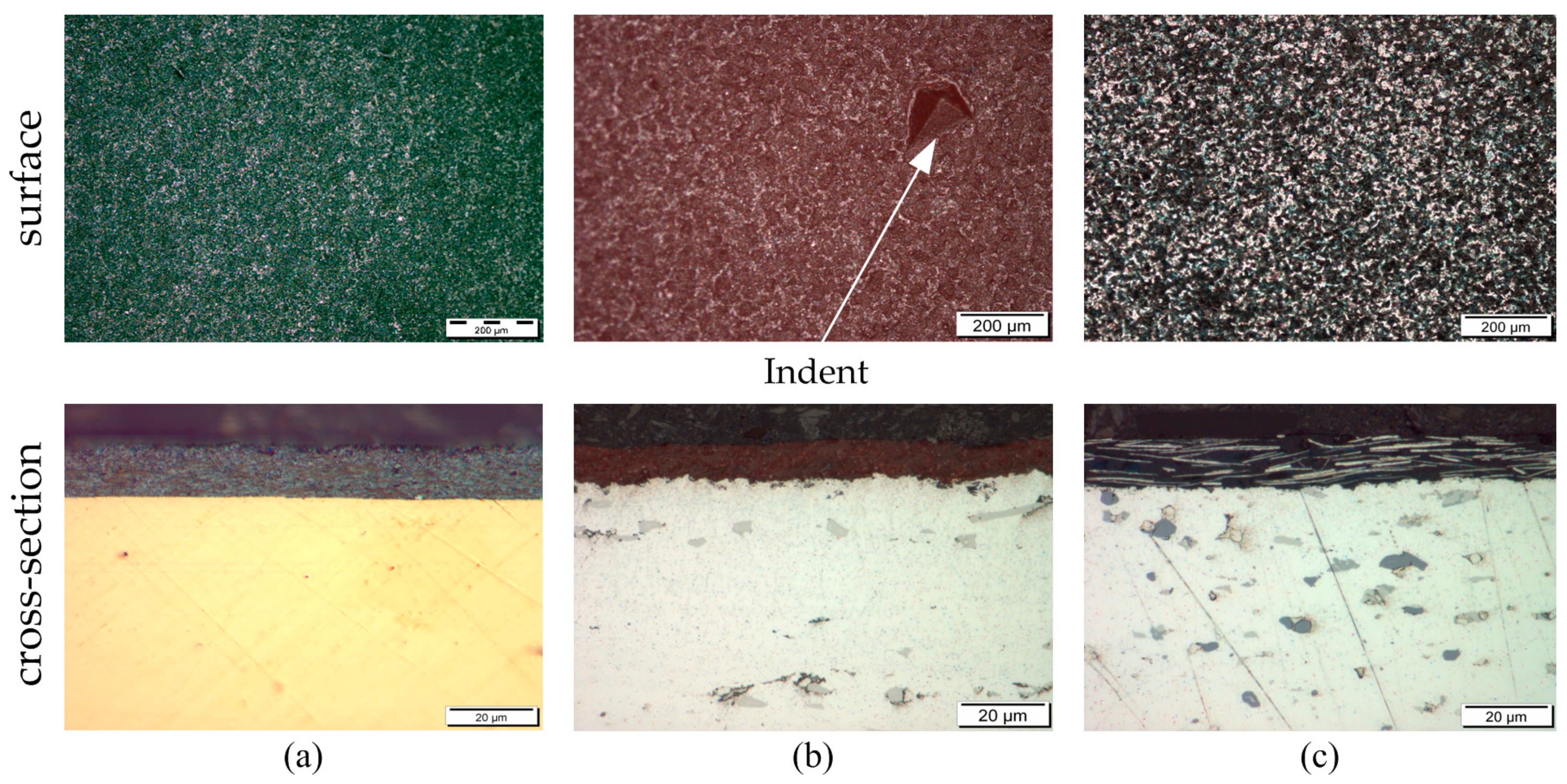
In
Figure 1, LIMI analysis of all three bearings are depicted and compared. For polymer bearing 2 (PB_2) and polymer bearing 1 (PB_1), the top surface has a fine structure. The surface of polymer bearing 3 (PB_3) has a rougher structure, showing a flaky pattern. For all three variants, a top surface polymer film is evident. Furthermore, all surfaces appear quite rough, which is likely to be a consequence of the spray coating process used to apply the polymer/filler overlay. The LIMI analysis of the micro sections gives further insight into the different layered structures for each bearing. All three bearings are armed with a steel backing onto which the bearing lining and the corresponding polymer overlays are applied. PB_2 and PB_3 are composed of similar lining matrix materials, which portray a characteristic aluminium coloured lustre. These are equipped with different hard and soft phases which also differ in colour. For example, PB_3 contains silicon, intermetallic and tin phases, whereas PB_2 contains intermetallic and tin phases only (based on elemental point analysis). In contrast, PB_1 features a different lining material, showing an orange colour in the light microscopy images. With the aid of elemental analysis this can be attributed to a lead free bronze lining material. LIMI analysis also reveals differences in the microstructure of the different polymer overlays. PB_1 and PB_2 exhibit fine microstructures with a homogeneous distribution of filler particles within the polymer matrix. In contrast, PB_3 contains larger phases, which are orientated in parallel to the surface. The average coating thicknesses measured for PB_1, PB_2 and PB_3 are 16 µm, 8 µm and 10 µm respectively. In case of PB_2 and PB_3 the lining-overlay transition appears slightly roughened, whereas for PB_1 the transition is smoother.
In order to resolve the layer composition and structure of the polymer coatings, high resolution SEM and EDX analysis and local sample preparation using the ion slice technique have been carried out.
Figure 2,
Figure 3 and
Figure 4 show the results for the various bearing coatings.
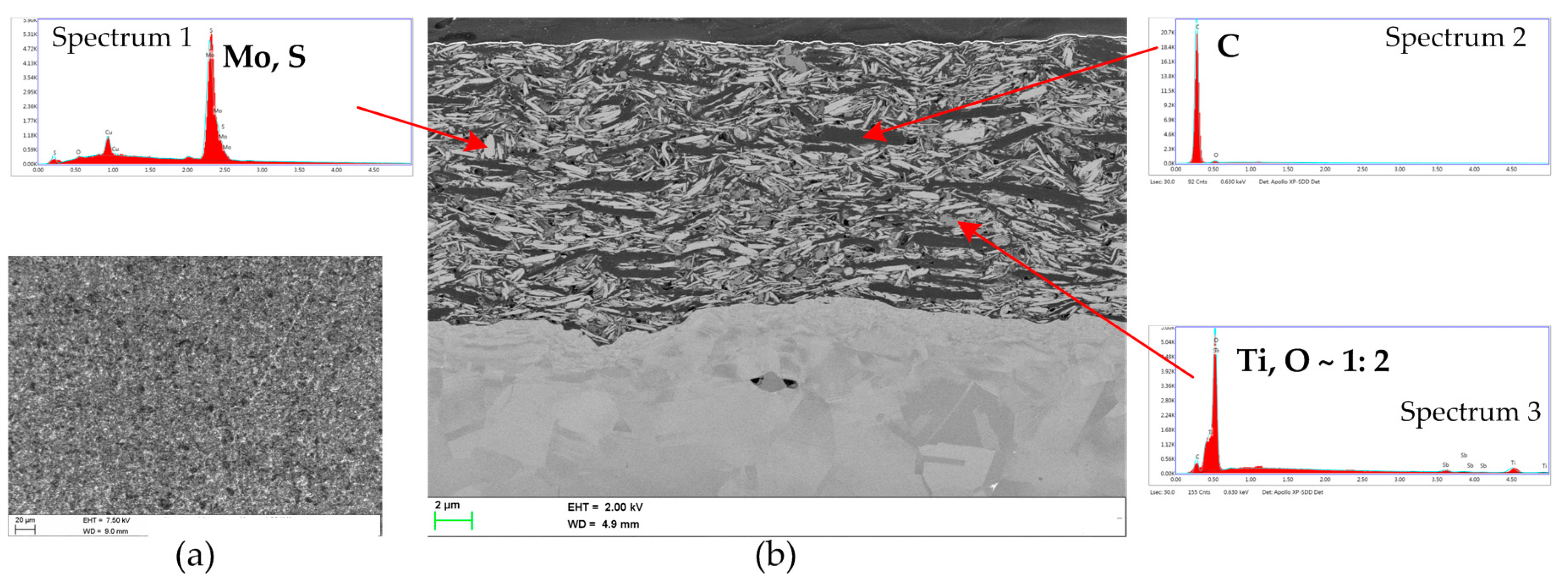
Figure 2 depicts the analysis performed for PB_1. The analysis highlights that the polymer overlay has a densely packed structure. Different phases can be seen in the material contrast images of the surface (
Figure 2a) and cross section (
Figure 2b) obtained via SEM. EDX point analysis and the corresponding X-ray spectra identified three different fillers. Firstly, molybdenum and sulfur have been measured (Spectrum 1) with an atomic ratio of 1:2, thus indicating the presence of MoS
2 phases. The MoS
2 phases appear to be the dominant filler material. In addition, larger carbon based phases (indicating graphite) are seen, see Spectrum 2. In between, smaller particles consisting of titanium and oxygen with a ratio of 1:2, hence potentially TiO
2, are found (Spectrum 3). Due to the tight packing of the filler materials, pure polymer matrix areas are barely detectable.
Figure 3 shows a similar analysis for PB_2.
Figure 3a is taken on a larger scale, thus highlighting the pre-described structure of aluminium lining material matrix, tin phases (bright) and intermetallic phases (average grey). In addition, a bonding layer between the lining and steel backing (bright grey) is seen.
Figure 3b provides a higher resolution image of the polymer coating. Similarly, to PB_1, the polymer matrix is densely packed with various filler phases. The most dominant phases consist of boron and nitrogen in a 1:1 atomic ratio (Spectrum 2), thus indicating the presence of boron-nitride (BN) fillers. In addition, particles containing silicon and carbon (Spectrum 1) are also present alongside smaller particles, potentially containing iron and oxygen (Spectrum 3). Furthermore, in this case the polymer matrix is filled up extensively with the various filler materials.
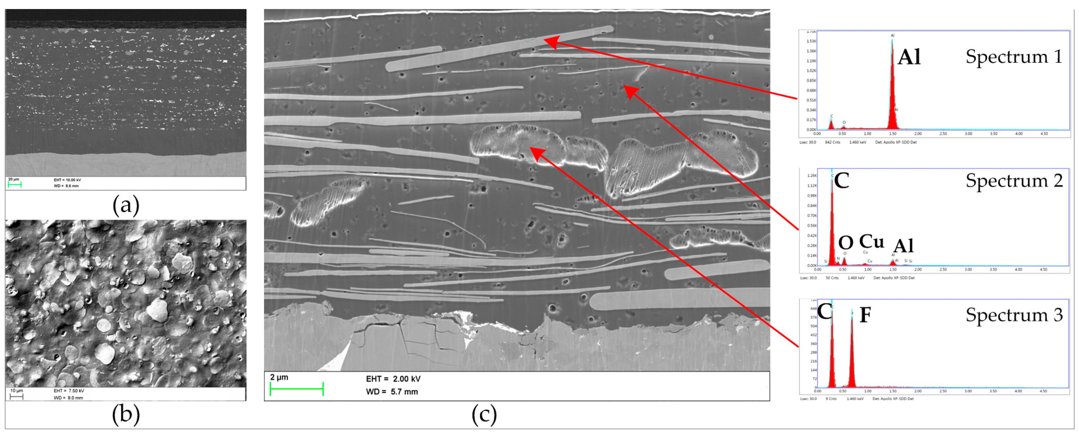
Details of the material structure and composition of PB_3 are provided in
Figure 4. In
Figure 4a, the lining material is visible in the cross section view using backscattered electron imaging. As described above, different phases are evident (e.g., intermetallic phases and tin as a soft phase in relation to aluminium) within the aluminium matrix material. Regarding the coating composition and structure, most conspicuously the coating features many “disc” shaped larger phases as seen in both the cross section view (
Figure 4c) and the surface images (
Figure 4b). These correspond to aluminium metallic phases (Spectrum 1). Additionally, the cross sectional images combined with elemental analysis also highlights the presence of further filler materials. Fluorine was detected in the larger cavity-like regions in
Figure 4c. This is likely to correspond to the presence of polytetrafluoroethylene (PTFE) as a solid lubricant filler (Spectrum 3). Smaller particles are also visible within the matrix, consisting of aluminium, copper, carbon and oxygen (Spectrum 2). Considering the interaction volume of the elemental analysis aluminium, carbon and oxygen could originate either from these smaller particles or from the surrounding disc-shaped aluminium particles and polymer matrix.
3. Experimental Methodology
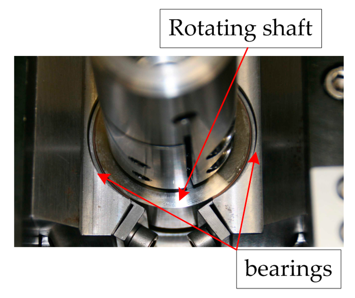
The experimental part of this study focussed on laboratory tests conducted using a sub-scale test system, recording various tribological parameters (e.g., the coefficient of friction). The test results are interpreted alongside damage analysis using the LIMI and SEM/EDX techniques, in a similar manner to the bearing characterization studies. The sub-scale tribotests were carried out on a TE92 tribometer from Phoenix Tribology Ltd. (Kingsclere, England) using a unique test set up whereby real-scale bearing shells and shaft components were implemented. In doing so, the test system enabled running of all lubrication regimes across the Stribeck curve. The test system was named the bearing segment tester (or otherwise also bearing adapter) and has already been presented previously in detail [
17]. A depiction of the set-up is shown in
Figure 5. For each bearing product, specific holders were designed with similar geometric properties to the engine application. This ensured correct fitting of the bearing shells within the specimen holders. The shells were pushed against a rotating shaft piece. The contact was oil-bath lubricated, which meant the contact was oil immersed in a 100 mL oil bath. Normal force was applied pneumatically through the shaft holders to the system. The test set-up was well equipped with several sensors measuring various parameters such as the coefficient of friction (
µ), oil bath temperature, bearing back temperature, contact potential (CP), etc. The sliding speed of the shaft samples was generated by direct connection to a servomotor. The nominal bearing clearance for all tests was set to 1.6‰ with a diameter size of the shaft between 48 and 50 mm depending on the used bearing material.
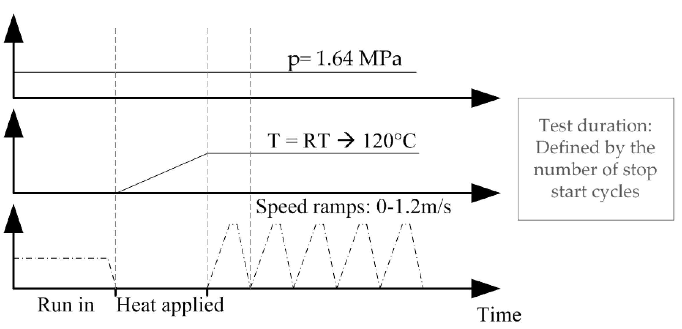
In order to study bearing wear performance and friction behaviour for different lubrication regimes and various engine applications, stop start sliding was targeted. Samples were tested following a stop start test program depicted in
Figure 6. The test strategy started with an initial period at a slower sliding speed at room temperature to facilitate mild running in. Thereafter, the oil was heated during still-stand to an oil bath temperature of 120 °C before stop start sliding was performed up to a maximum speed of 1.2 m/s. The speed ramps were conducted as quickly as possible to mimic engine stop starts. A total ramp duration from 0 to 1.2 m/s and vice versa lasts 8 s. The test duration varied according to the number of stop start ramps, which ranged from 20,000 to 70,000.
The tribometric data is recorded at a standard data acquisition of 1 Hz. In addition, selected speed up ramps were recorded with a higher speed data acquisition of 1 kHz in order to record the friction performance with higher precision. For data evaluation, the recorded tribo data is plotted vs. test time for 1 Hz data acquisition and vs. rotational speed for 1 kHz data acquisition. The bearing wear was measured ex-situ by comparing the bearing shell thickness before and after the tests at 15 positions equally distributed over the bearing width (3 rows) and on 5 angular positions (wear measurement grid). This was carried out with the aid of a special measuring device using a high precision dial gauge.
For all tests, the same lubricant and shaft material have been used. The lubricant used was a fully formulated SAE grade 10W-40 engine oil and the shaft material used was a conventional crankshaft material (viz. 34CrNiMo6).
4. Experimental Results
Several experimental tests have been carried out in order to visualize friction and wear performance of the various systems.
Table 1 lists the tests conducted with various numbers of stop start cycles for each of the three bearing materials. Each number of stop start cycles listed in
Table 1 refers to an individual conducted test. Initial tests were conducted with PB_1 and the same number of stop start cycles (50,000), in order determine the test reproducibility. As can be seen in the latter part of the paper, both friction and wear results are highly reproducible. All three materials have been tested at both 18,000 and 50,000 stop starts for a direct comparison, whereas for other cycle numbers only selected tests have been conducted in order to depict the evolution of damage and friction losses.
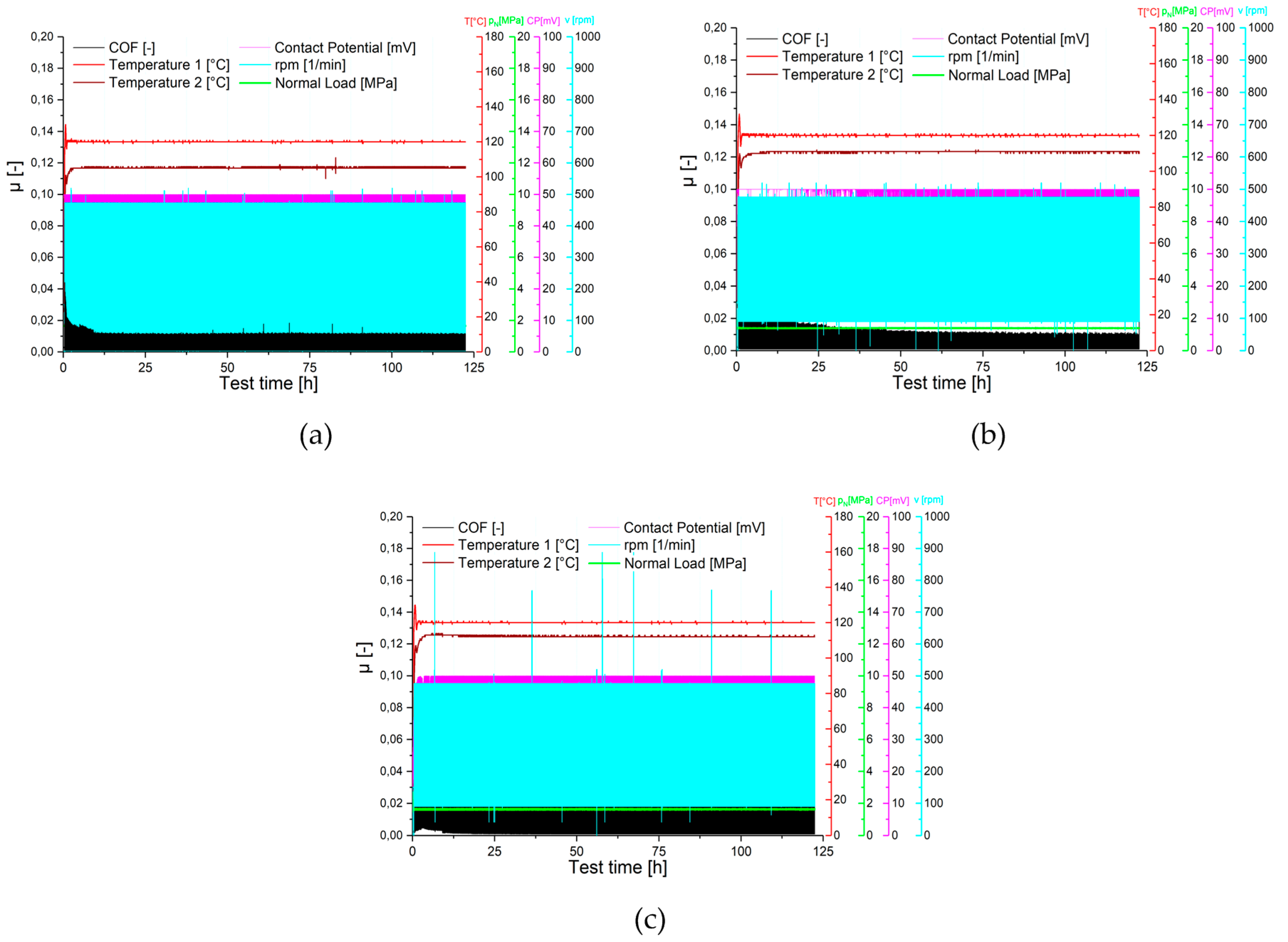
Figure 7 depicts the multiple output values vs. test time recorded at the lower data acquisition value of 1 Hz. Representative tests for each bearing material are reported for the same test duration. These low speed acquisition plots depict only averaged output values for each speed ramp. Although this data collection provides limited detailed information, the long-term behaviour of stable or unstable sliding conditions can be easily and clearly observed. In general, for all three bearing coatings, stable system temperatures are achieved. As stated before, the oil bath temperature (plotted in bright red) represents the set value of 120 °C. Similarly, the bearing back temperatures of all experiments are stable throughout the tests. The values settle around 110 °C for PB_2 and PB_3, whereas for PB_1 the temperature is slightly lower at 105 °C. The lower temperature values of the bearing back compared to the oil bath set value imply that significant frictional heating is not created during the tests. This effect is more pronounced for PB_1. This is also clear from the friction values (black lines), which show consistently low values. In addition, for all bearing products, a running in period during the first few hours of testing is observed, which settles to a constant value for the rest of the test duration. As shown in
Figure 7, PB_1 demonstrates the lowest need for running in.
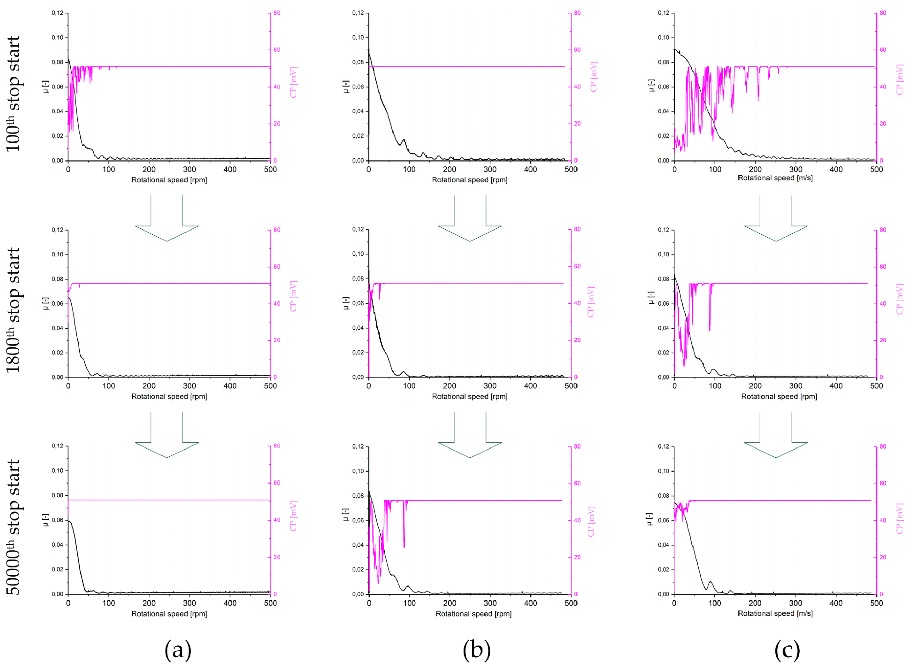
A more detailed evaluation was conducted with the aid of faster data acquisition rates for selected speed ramps. In
Figure 8, data collected at an acquisition rate of 1 kHz is depicted with the coefficients of friction (
µ) and contact potential (CP) plotted against the rotational speed for a single ramp up. These plots are shown for tests conducted after 100, 1800 and 50,000 stop start cycles for each of the three polymer coatings. For each material, the evolution of the lubrication regimes, the changes of the static friction, the amount of mixed friction and the transition point between mixed and hydrodynamic friction are evident. Particularly during the initial stop start ramps, PB_1 shows a lower amount of mixed friction (see comparison of the friction curves of the three bearing materials during the 100th stop start ramp in
Figure 8).
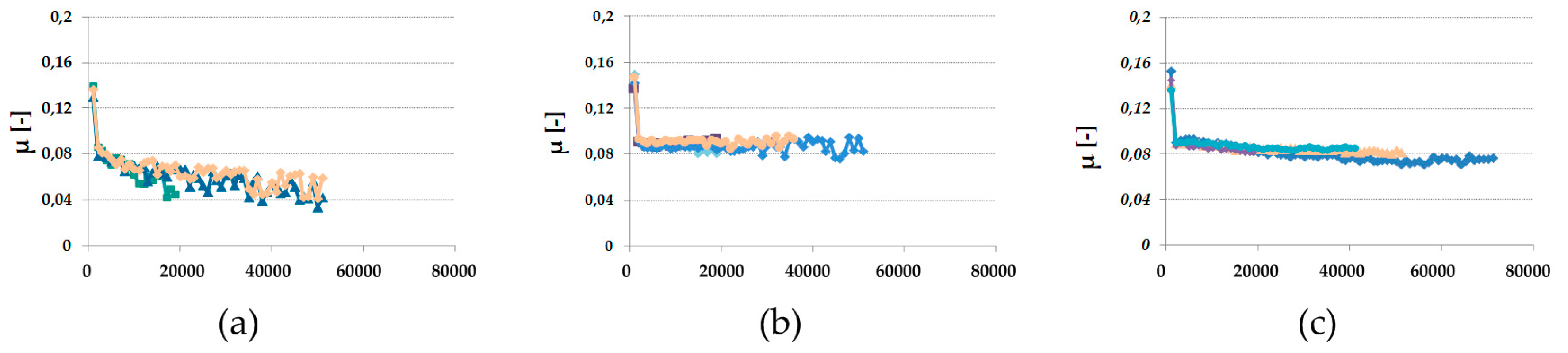
In addition, the evolution of the static coefficient of friction (friction coefficient during start of relative motion) can be compared.
Figure 9 demonstrates this comparison for all tests conducted. All three polymer overlays show a significant running in phase where the static friction drops significantly below 0.1. After the running in phase, a small decrease in the static friction is observed for PB_2 and PB_3, whereas a more pronounced decrease in the friction coefficient is observed with test time for PB_1, to values as low as 0.05. Additionally, all tests for one bearing type result in high reproducible friction values.
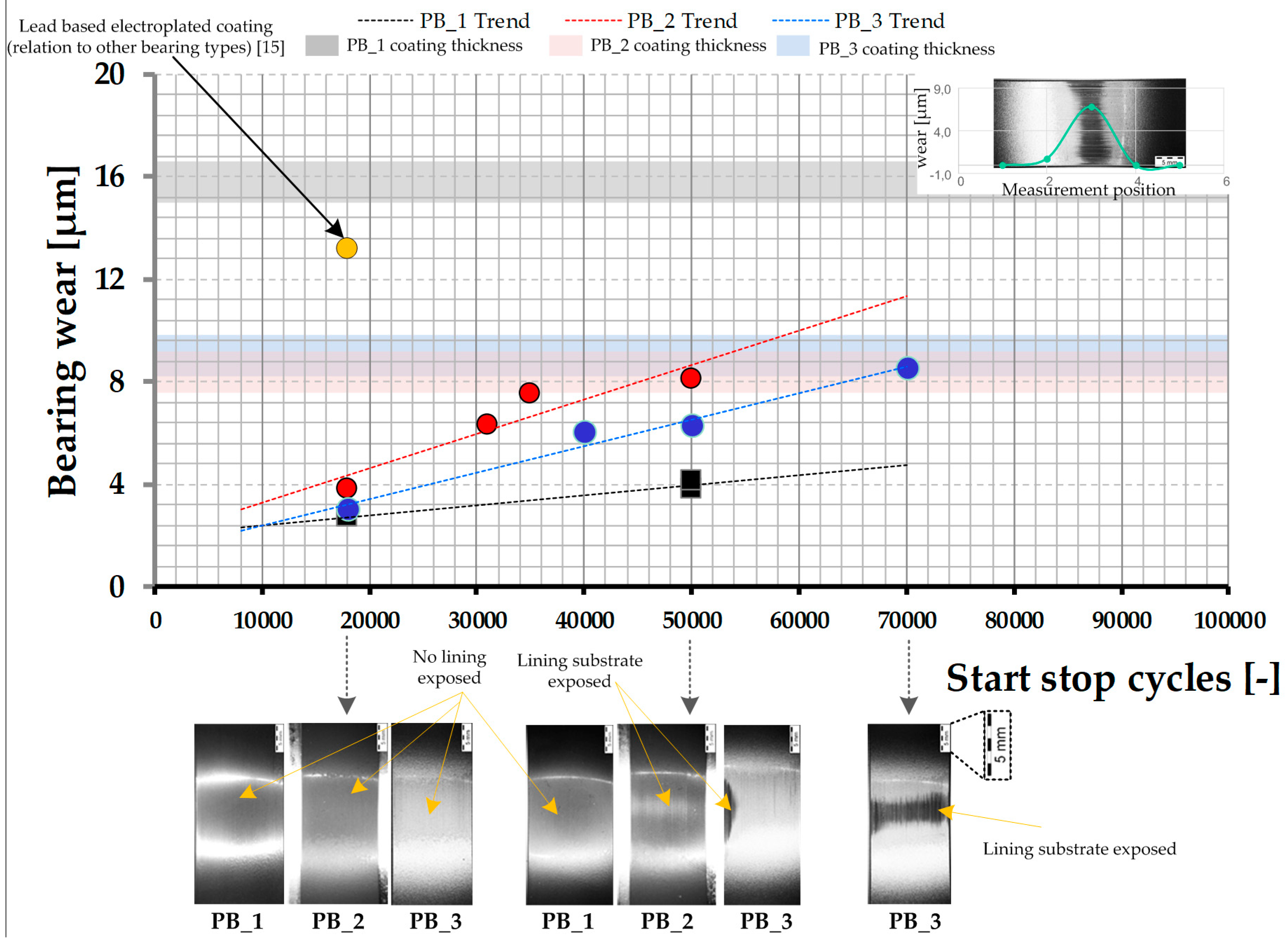
In addition to friction performance, the durability of the bearing coatings has been investigated. Therefore, the bearing wear for each polymer overlay has been assessed.
Figure 10 shows the maximum bearing wear at the highest loaded position vs. the number of stop start cycles performed for all tests. These results are compared to a reference wear result for a standard lead based trimetal bearing. In addition, in the right upper corner a stacked illustration of a full wear profile and the corresponding contact pattern is provided.
When assessing the amount of wear for 18,000 stop start cycles the superiority of polymer overlays in comparison to a standard metallic trimetal bearing is evident. While all three polymer coatings result in a similarly low levels of wear below 4 µm at the highest loaded position, the trimetal bearing displays 3–4 times more wear and thus nearly almost the whole overlay thickness is worn for same test duration and conditions. Similar findings have been published previously [
14]. The running patterns for the polymer bearing products are also shown in the bottom part of
Figure 10. The running surfaces are smoothened and appear brighter compared to the non-contact regions.
For all three polymer coatings the wear evolution during pure stop start testing appears to be linear after running in and wear through of the overlays. This is shown by the dotted trend lines calculated from the wear measurements in
Figure 10. The wear results also demonstrate a clear ranking among the polymer overlays with regards to the stop start wear resistance under the given conditions considering that the main damage processes take place under the boundary lubrication conditions at low speeds and that the systems can be compared with each other also with minor differences in the overlay thickness and other parameters slightly changing the thermos-elasto hydrodynamic characteristic of the bearing systems. While for the lowest stop start cycle number of 18,000 the wear amount is nearly the same, the wear evolution diverges in the further course of testing (viz. higher stop start cycles). PB_2 shows the lowest wear resistance and highest wear rate under these test conditions. After 50,000 stop starts the overlay is locally worn, exposing the aluminium substrate at the highest loaded positions. This is shown in the overview images of the running patterns. PB_3 provides slightly lower wear values as shown in
Figure 10 with exposure of the lining occurring at approximately 70,000 stop start cycles under the test conditions used for this study (Note: For one test with PB_3 bearing, the lining substrate has already been exposed after approximately 50,000 stop starts but outside of the wear measurement grid at the edges due to potential mis-alignment). PB_1 provides the greatest wear resistance with only approximately 4 μm of wear occurring after 50,000 stop start cycles. The overview pictures of the running patterns demonstrate the retention of the bearing overlay over the whole bearing shell after testing. Longer tests to fully wear the polymer overlay of PB_1 have not been conducted due to a lack of specimen and the long test duration required to achieve this.
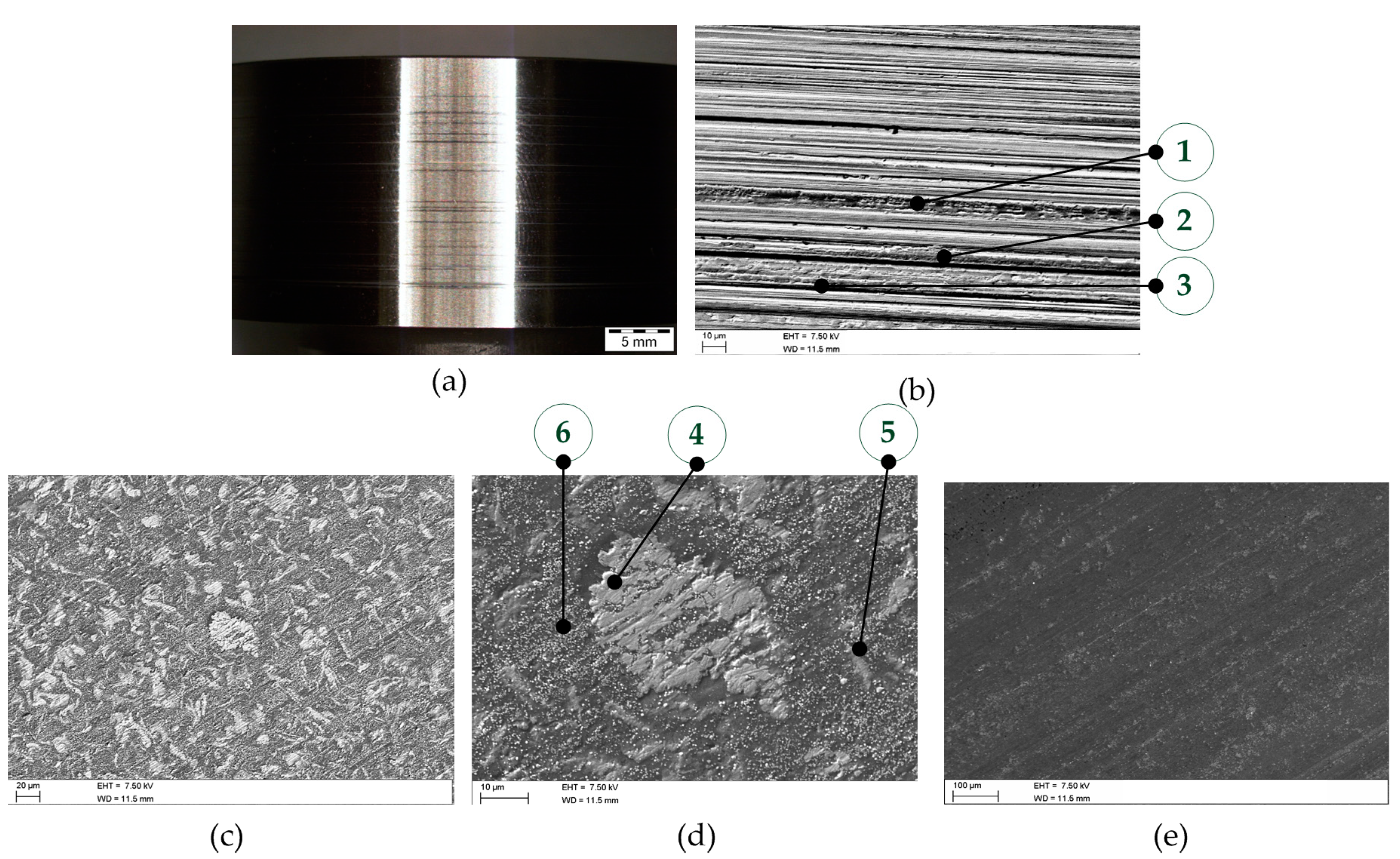
Additional post-test surface analysis was carried out to probe the surface mechanisms dominating the friction and wear performance. For PB_3 representative surfaces are shown in
Figure 11. On the shaft specimen (
Figure 11a) sliding marks are seen for all tests. With the aid of SEM/EDX analysis (
Figure 11b,
Table 2, Spectra 1–3) zinc dialkyldithiophosphate (ZDDP) degradation elements such as phosphorous, zinc and sulphur have been detected. These elements are mostly located at the sliding grooves due to the increased pressures and temperatures in these localised areas, thus tribologically protecting the contact from wear. The coating composition of the upper bearing surface after running in is dictated by the filler structure. Both the aluminium filler particles and PTFE solid lubricant are present on the top surface (see
Figure 11c). The aluminium particles are over the majority of the surface and appear slightly exposed (
Figure 11d,
Table 2, Spectrum 4). Furthermore, elemental analysis also highlights that the aluminium particles are slightly oxidized as a result of contact processes. PTFE is detected due to the presence of fluorine at the upper bearing surface (
Figure 11d,
Table 2, Spectrum 5) and appears smeared in local regions. ZDDP anti-wear film deposits are detectable in the form of small spheres also on top (
Figure 11d,
Table 2, Spectrum 6). As stated before for extended tests, the aluminium substrate material is exposed locally (
Figure 11e). Wear marks are visible on the lining material but no severe damage (for example, scuffing marks) are detectable. Hence, also in this case mild wear is the dominant damage mechanism.
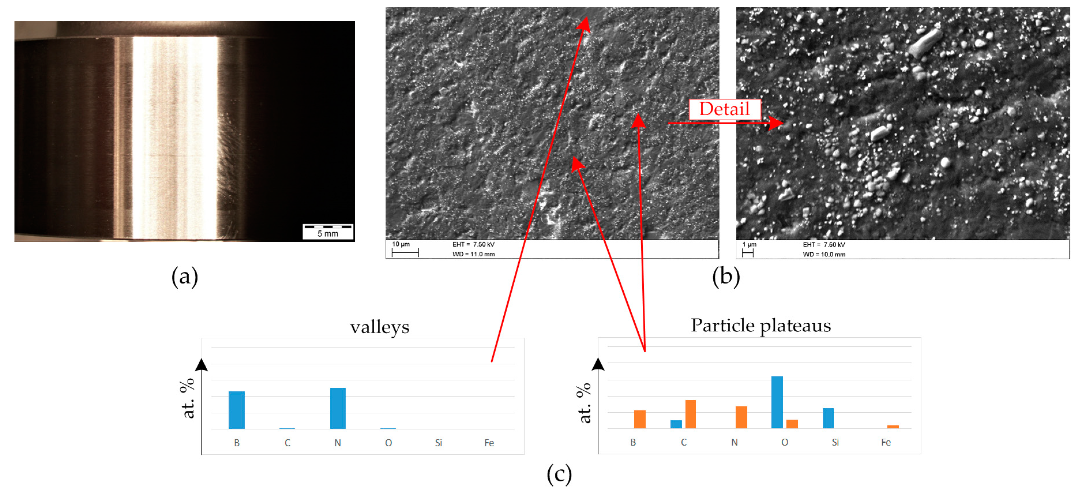
For PB_2, the shaft surfaces (
Figure 12a) show only minor changes (i.e., minor sliding marks and a reduction in roughness) compared to the initial condition. During the initial sliding, the top surface of the bearing decreased in roughness, and partial removal of the polymer overlay occurred. Simultaneously, the filler materials contained within the polymer matrix migrated to the contact interface. This can be linked to the reduction in friction during the first Stribeck cycles. After this a particle structured surface formed on the polymer coating, which was composed of the smaller carbide phases and metal oxide particles. The B–N solid lubricant phases were not detected at the top of this particle active network but rather beneath still embedded in the polymer matrix. This can be seen in
Figure 12b, which shows representative surface images of the bearing surface after stop-start sliding. The carbide and metal oxide micro-particles are exposed, and appear to cover the whole bearing surface (particle plateaus shown in elemental analysis in
Figure 12c), while the B–N phases are embedded beneath in the polymer matrix (valleys). These surface processes take place until the substrate becomes exposed and a mixed overlay and lining surface is evident. Despite exposure of the aluminium lining material, similar to PB_3, only mild wear phenomena occur, with no scuffing or seizure marks.
Figure 13 depicts representative surface conditions for PB_1 after stop start testing. Similarly to PB_2, no significant sliding marks are visible on the shaft specimen, as shown in
Figure 13a. The steel surface is smoother in comparison to an unused shaft specimen, but deeper sliding grooves are not detectable. Moreover, as for PB_2, ZDDP degradation products i.e., ZDDP anti-wear layers can barely be detected via SEM/EDX point analysis for this bearing under the given test conditions (on neither the bearing nor shaft surfaces). At this point, it is worth noting that the lack of detection via SEM/EDX point analysis (i.e., localized analysis and deeper penetration depth) does not necessarily mean a thin tribofilm (with nm thickness) or thicker localized films on other areas of the surfaces are not present. The bearing overlay shows a fast activation of the filler materials via formation of a dense particle structured surface comprising all filler types included in the coating after running in and removal of the covering polymer.
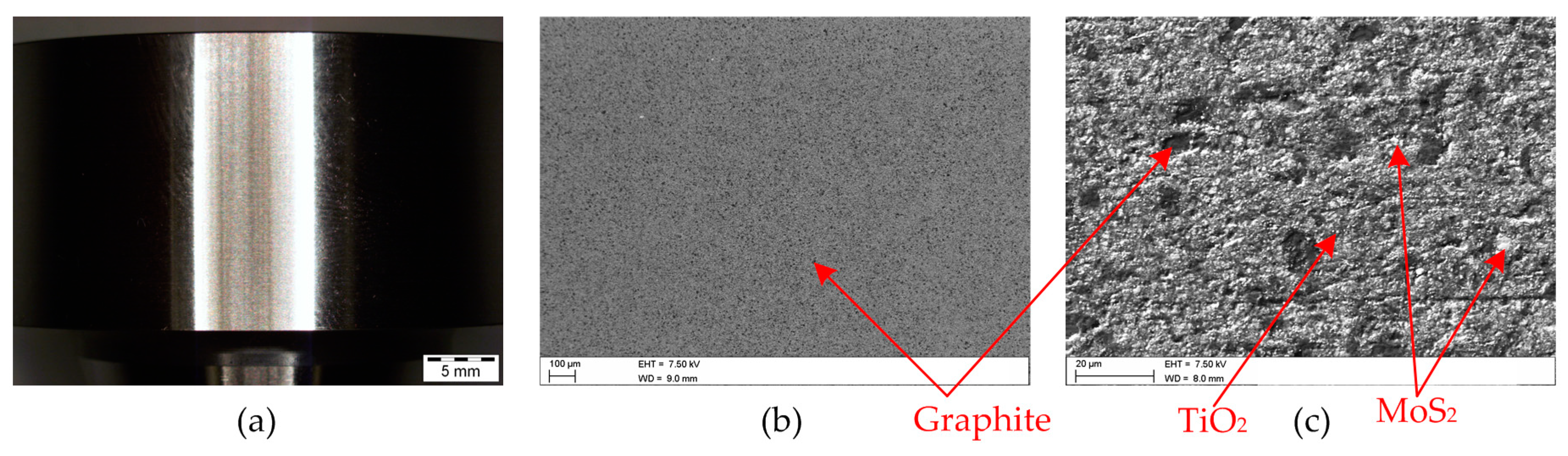
Figure 13c shows a representative bearing surface composed of MoS
2, graphite and the smaller TiO
2 particles. It is worth noting that for this condition almost no pure polymer matrix regions can be identified on the top surface. This is likely to contribute to the lower coefficients of friction observed for this polymer bearing in comparison to PB_2 and PB_3. Furthermore, MoS
2 and graphite are known solid lubricant materials, and therefore enable low friction environments, as shown by Kagohara et al. for MoS
2 [
18], but also provide load bearing functions as shown by Grün et al. [
19]. In addition, the dense filler network also seems to provide high wear resistance based on the current wear results.
5. Summary
This study comprises research activities in the field of journal bearing technology, specifically the functionality of bearing systems and bearing materials. In particular, the work investigates polymer bearing coatings, focusing on their tribological performance in relation to stop start wear. Surface lubrication interactions, as well as bearing structure and composition were analysed to evaluate the friction and wear performance for each bearing coating. All these aspects have been assessed with light and electron microscopy aided by elemental analysis in combination with tribological testing. The three polymer bearings investigated differ significantly with respect to the lining material and polymer filler structures. Each polymer coating utilises different filler types. PB_1 is composed of a bronze lining material, with a polymer overlay containing MoS2, graphite and TiO2 phases as fillers. The fillers are densely packed, resulting in a low amount of free polymer matrix regions during sliding. In contrast, the PB_2 polymer overlay is applied to an aluminium based lining and contains B–N, Fe–O and Si–C particles. The PB_3 polymer overlay is also coated on an aluminium lining material and contains aluminium and PTFE fillers as well as potential aluminium and/or copper based nanoparticles.
Under stop start conditions, mild wear was identified to be the dominant damage mechanism for polymeric bearings studied. This was also seen for extended test durations, when lining materials were exposed. Hence, seizure damages were not observed. Stop start wear performance of the various bearing materials were all superior compared to a conventional trimetal bearing. For all three polymer bearings tested load bearing particle structures were identified on the bearing surfaces during stop start sliding, contributing to the high wear resistance for this operation condition. However, between the various polymer coatings, PB_1 showed the highest wear resistance, followed by PB_3 and then PB_2. In case of friction performance, PB_1 also demonstrated the best performance, i.e., low boundary friction and a greater proportion of operation in a hydrodynamic friction regime. Surface and damage analysis suggests that the lower friction performance, as well as the slightly improved wear performance, of PB_1 is a consequence of the high levels of solid lubricants with a hexagonal molecule structure also providing load bearing functions, which are densely packed in the polymer matrix.


