1. Introduction
Tilting-pad journal bearings (TPJBs) have been widely used to support the rotors of high rotational speed machinery such as steam and gas turbines. The dynamic stiffness and damping coefficients of fluid-film journal bearings in large turbine were experimentally evaluated very early [
1]. Year by year, many research projects have focused on the prediction and measurement of static and dynamic behaviors of four-pad, five-pad TPJBs in load-on-pad and load-between-pad configuration [
2,
3,
4,
5,
6]. In order to obtain accurate results for static and dynamic characteristics of TPJBs, the analytical model has been improved using the measured transfer functions between the rotor and the pad motion [
7,
8]. During the years, the role of pivot flexibility in TPJBs has become essential, particularly for bearings working at high applied load and relatively high rotor speeds. Studies on TPJBs by introducing the pad-pivot flexibility into the mathematical model allow more accurate results to be obtained.
D. Childs et al. in [
9] presented the dynamic coefficients of a flexure-pivot four-pad TPJB running at high speed in load-between-pad configuration obtained by experiments and simulations. The model used an isothermal analysis for a bulk-flow Navier-Stokes (NS) model. The authors concluded that by adding a constant mass matrix to the flexure-pivot bearing model gives a precise frequency-independent model that cancels out the need for iterative rotordynamic stability calculations. Several investigations about the flexure-pivot bearing were performed by the same authors [
10,
11,
12].
Dmochowski in [
13] analyzed the effect of the excitation frequency on the dynamic stiffness and damping characteristics of a five-pad TPJB due to pivot flexibility using experimental and theoretical investigations. He concluded that the pad inertia and pivot flexibility have a strong influence on the variations of the stiffness and damping properties with the frequency of excitation.
Kim Thomsen and Peder Klit in [
14,
15] provided the guidelines to the design of the pads and the polymer liner for a hydrodynamic journal bearing with flexure pads. Authors found that the use of flexure pads was a perfect method to pivoted pads. When combined with a polymer liner, the bearing performance is significantly improved, particularly at thin lubricant films.
The dynamical characteristics of the TPJBs with a variable pivot stiffness were studied by San Andres and Tao in [
16]. Authors stated that the influence of pivot flexibility on the dynamic coefficients is insignificant only if the oil film stiffness is one order of magnitude smaller than the pivot stiffness. On the other hand, for the pivot stiffness of one order of magnitude smaller, the bearing stiffness is only estimated by the pivot stiffness. Importantly enough, flexibility of pivot increases the bearing dynamic stiffness as a function of the excitation.
Matthew et al. [
17] studied the effect of pad compliance by changing the pivot geometry and Young′s modulus of the pad backing and pad liner on the dynamic characteristics of TPJBs. Authors found that higher compliance of pad backing significantly modifies the shaft locus and results in an increase in oil film pressure while oil film thickness is decreased. Besides, the oil film pressure is decreased while oil film thickness is increased if a compliant liner is used.
Dynamic characteristics of polymer faced TPJBs were investigated in [
18]. Two polyether ether ketone (PEEK) faced pads, one polytetrafluoroethylene (PTFE) faced pad and two entirely PEEK pads were studied to identify the influence of variable bearing pressure, pivot features and different material of the polymer layer. It was found that the entirely PEEK pads were quite a lot hotter than the steel backing pads. If PTFE is used instead of the PEEK liner, the stiffness with equivalent damping will slightly be reduced.
Also, the dependence of the dynamic behaviors on the flexibility of the pad and pivot for a TPJB were investigated in [
19]. In this study, authors took into account the variations of the clearance profile with the operating temperature of the system and identified the discrepancies of dynamic coefficients between the prediction and measurement when varying dynamic excitation. The clearance profile with a pentagonal shape for a five-shoes TPJB as a function of the operating temperature was achieved. The clearance profiles in hot and cold conditions were plotted. The results showed that the cold clearance profiles were approximately 30% larger than the hot ones. The effect of pad flexibility on the performance of TPJBs was studied in [
20,
21]. It was found that both load-between-pad (LBP) and load-on-pad (LOP) configurations show similar characteristics; the journal eccentricity increased with the pivot flexibility. For LBP and LOP bearings with 0.27 preload factor, the pivot flexibility decreases dramatically the bearing damping coefficients, in particular at high loads.
A detailed study about the performance of TPJB was presented in [
22,
23]. In these investigations, the thermal deformations of the pad and journal along with the pivot flexibility have been considered in the full three-dimensional TEHD model by using finite element method. Authors estimated the pivot stiffness using the Hertzian contact theory by supposing oval contact for the cylindrical pivot. The pivot stiffness was added to the fluid film stiffness and the simulation results were compared to previous publications. The results showed that the pad flexibility has smaller influences on the performance of the TPJB as compared to the pivot flexibility.
The performance of the TPJBs with different pivot stiffness was studied using numerical simulation [
24]. It was found that if the model considers the pad-pivot flexibility, the minimum oil-film thickness will increase in comparison with the fixed pads.
The pad temperature and film thickness of two real-size three-pad TPJBs were studied in [
25] with an elastic-pivot pad. The flexible rotor-active TPJB modelling with hybrid lubrication was thoroughly covered in [
26,
27]. The paper showed a slight improvement on the system dynamic performance by using the hybrid lubrication instead of the passive one. Recently, the dynamic behaviors of a composite TPJB for turbine/generator applications were shown in [
28]. Authors stated that the composite TPJB effectively decreased the rotor vibration and increased the stability and durability of the bearing system compared to the white metal bearing.
The effects of pivot flexibility to the behaviors of the TPJBs with ball-socket and rocker-backed pivots were investigated in [
29]. The static and dynamic characteristics were studied using a thermo hydrodynamic model with non-rigid pivots, and the pivot stiffness was estimated by applying the Hertzian contact theory. The paper showed that the model with soft pivot allows better results than the rigid ones to be obtained.
Yingze Jin et al. [
30] presented the nonlinear dynamic behaviors of tilting-pad journal bearing with adjustable elastic pivot structure. The authors stated that the TPJB performances can be easily adjusted by pivot stiffness, pre-tightening force and preload factors.
The effects of the flexibility of the pad and pivot on the linear as well as non-linear performances of TPJBs were also studied by many authors in [
31,
32,
33,
34,
35]. The pivot stiffness is usually modelled by means of the Hertz contact theory by taking into account for the material and geometry of the pivot mechanical elements, mainly the radii of curvature of the pad/pivot and bearing housing.
However, most of the studies of TPJBs in the literature used the pivot stiffness obtained from the Hertz contact theory. Other papers performed the experiment to estimate the pivot stiffness, but they use the same stiffness for all pad pivots due to the configuration of the test-rig. With the test-rig in this research, the applied static and dynamic load can be varied in any direction. Consequently, the pivot stiffness on each single pad can be evaluated.
In this paper, a TEHD model was developed to identify the dynamical behaviors of two five-pad TPJBs: rocker-backed pivots bearing and spherical pivots bearing. In this model, the pivot stiffness of all pads was calculated using two methodologies: experimental measurement and Hertz contact theory. The experimental pivot stiffness calculation procedure is also presented. In order to validate the model, the experimental tests for identifying the dynamic coefficients were carried out. The clearance profile of the two tested bearings and the shaft center loci of the rocker-backed bearing by varying the static load direction, obtained by measurements and predictions are shown in order to highlight the effect of the pivot flexibility. Finally, the dynamic coefficients of the two bearings obtained by numerical simulations were compared with the experimental results.
2. TEHD Bearing Model
The TEHD model of the TPJB is similar to that developed and described by the same authors in [
36,
37,
38,
39] and improved for the thermal aspect, as partially done in [
40] for sleeve journal bearings. The model mainly includes the laws of hydrodynamic lubrication, the thermal model of the oil-films, pads and shaft and the flexibility of the pivots.
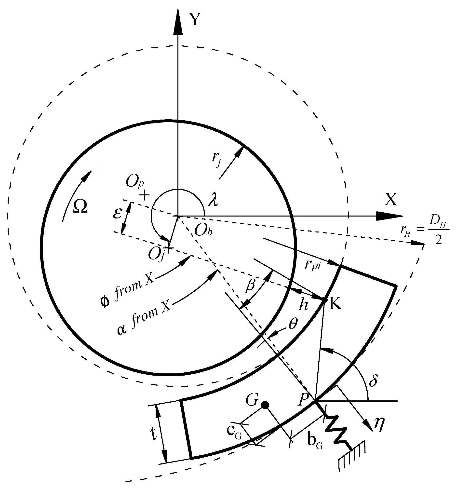
Figure 1 shows the sketch of a single pad in detail. The pad rotates about the line contact P by angle
. In the model, the pivot flexibility is taken into account by considering the movement along the radial direction
of the pad. The vector of the 2 + 2.N
pads degrees of freedom of the system is as follows:
where
xs and
ys represent the shaft centre position,
represents the tilt angle of the k-th pad, and
represents the displacement of the k-th pad along the radial direction due to the flexibility of the pivot.
The pressure distribution in each oil-film has been obtained by discretizing the well-known Reynolds equation using a finite-difference method on a two-dimensional rectangular mesh grid and considering a constant pressure in the oil-film thickness:
where
x is the tangential direction,
z is the axial direction,
h is the oil-film thickness,
p is the pressure in the oil-film,
is the oil mass density and
µ is the dynamic viscosity.
U1, V1 and
U2,
V2 are the shaft and the pads’ velocity vector component, respectively.
The energy equation of each oil-film, assuming laminar flow, is as follows:
The dynamic viscosity µ and the density
of the oil are supposed to be functions of the temperature
T only:
where
is the viscosity index and
is the thermal expansion coefficient of the oil.
Equation (3) has been integrated using a finite difference method, where adiabatic conditions at the shaft, pad surfaces and constant oil temperature in the oil film thickness direction are considered which correspond to a constant oil temperature along the direction of the oil-film thickness.
Moreover, the pad deformation has been taken into account and calculated using a finite element analysis. This deformation is caused by the pressure distribution and the thermal expansion. Then, the deformation on the pad surface will be added in the variation of oil-film thickness.
At steady state, the pad temperature distribution is as follows:
where
is the thermal conductivity of the material.
Assuming an isotropic material, the pad deformation (
u) because of the thermal and mechanical stresses is given by:
where
is the thermal expansion coefficient,
C is the tensor of mechanical properties and given by:
where
E is Young’s modulus and
is Poisson’s ratio of the material.
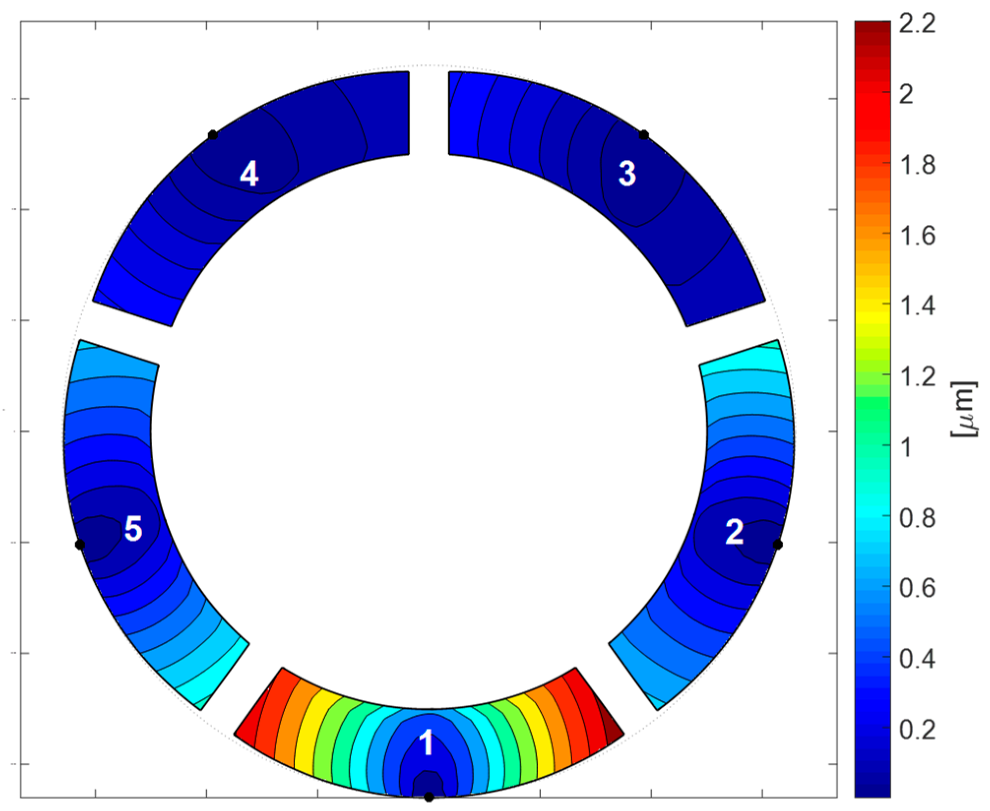
Figure 2 shows an example of the deformation of all pads when a static load of 5 kN is applied on pad #1 in the vertical direction when the rotor runs at a rotational speed of 1000 rpm.
Equation (3) shows the boundary conditions of a single pad and the pad mesh for finite element analysis. In the model, a tetrahedral mesh has been used for the finite element analysis (see
Figure 3b). Readers are strongly recommended to refer [
37] for deeply understand the model. Note that the pad model also considers two parts of each pad, i.e., the pad base (steel) and the pad sets (Babbitt layer with a thick of 3 mm).
Table 1 lists the properties of the two pad materials. Convection with oil at 40 °C with coefficient of q = 50 W/m
2 °C is applied on the other pad surfaces in order to evaluate the distribution of the pad temperature. Some additional boundary conditions are applied on all pad surfaces in order to consider the traction stresses for the evaluation of the thermal deformation. For the estimation of the pad deformation, the Dirichlet boundary condition with null displacement has been assumed for the upper surface of the pad-face
F2 (see
Figure 3a) corresponding to the pivot part. The pressure distribution obtained by the integration of Reynolds equation and the temperature distribution obtained by the 2D thermal model of the oil film, have been applied to the lower (active) surface of the pad. Furthermore, supplied temperature of 40 °C is assumed at the leading edge of the oil film.
The dynamic coefficients have been obtained by the four impedance coefficients of the impedance matrix
as given by [
36]:
The bearing dynamic coefficients are obtained as follow:
The impedance matrix
is given as follow:
where
and
are the linear stiffness and damping coefficient matrices, respectively, which are calculated for the
k-th pad, and:
where
is the mass,
is the pad mass moment of inertia and
is the position of the barycenter.
3. Test-Rig and Bearings under Test
A detailed description of the five-pad TPJB and the test rig is presented in [
36].
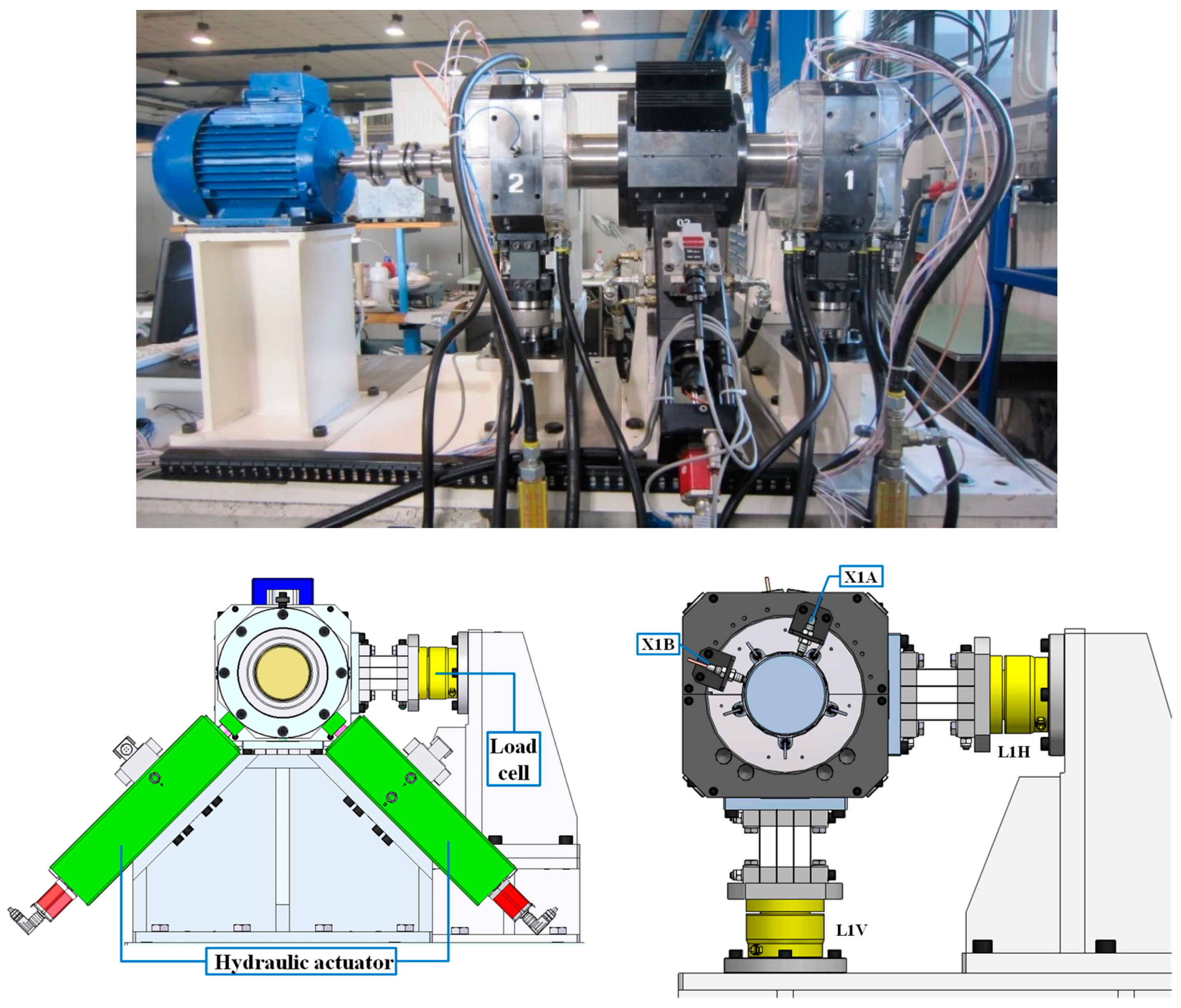
Figure 4 shows the picture of the test-rig for the experimental tests. In this test-rig, two identical five-pad journal bearings labeled as
1 and
2 are located at the end of the shaft and support the shaft. Only the bearing #1 which is placed at the non-driven end (
1 in
Figure 4) of the shaft is considered for the static and dynamic behaviors.
Two orthogonal 20 kN load cells (
L1H and
L1V in
Figure 4) decoupled by means of leaf springs were used to connect each bearing housing to the test rig frame. Two hydraulic actuators allow to apply the static and dynamic loads in the middle of the shaft. These two actuators are connected to the shaft through two ball bearings. Owing to this installation, the static and dynamic loads can be applied in any direction. The hydraulic actuators have a nominal force of 25 kN, are able to displace the shaft with an amplitude of 1 mm in the frequency band of 0–50 Hz and are provided by high-resolution position and force transducers. Two orthogonal proximity probes (
X1A and
X1B in
Figure 4) were installed on each bearing support to measure shaft-to-bearing housing relative displacements. Several different sensors are also used to measure the performance of the bearing such as accelerometer, temperature and pressure probes. The details of the installed sensors are listed in
Table 2.
A closed-loop PI temperature device is used to maintain the oil inlet temperature at approximately 40 ± 0.5 °C during the tests.
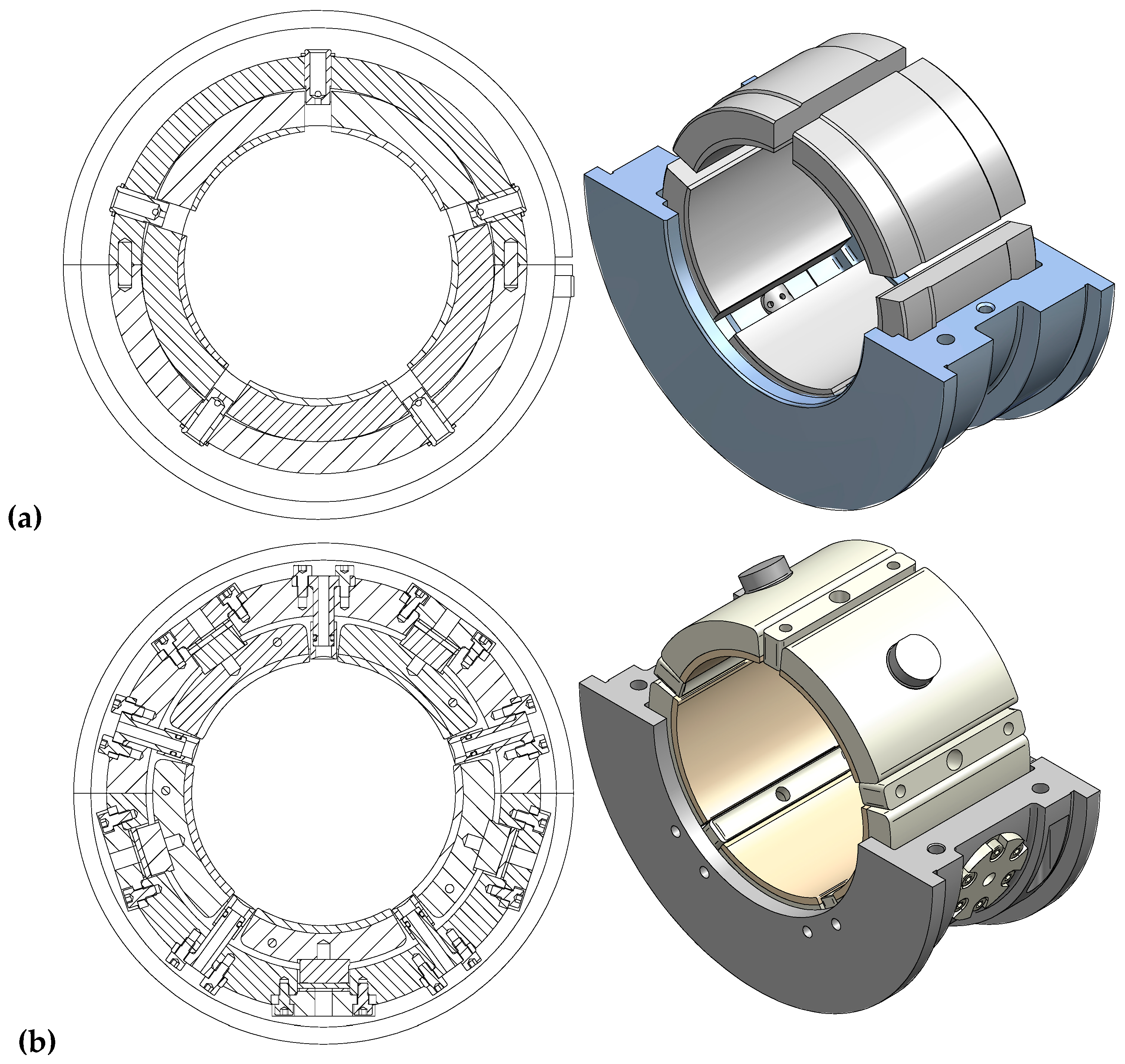
The bearings shown in
Figure 5a,b are a five-shoe rocker-backed and spherical pivot journal bearing, respectively. The bearing has a nominal diameter and a length of 100 and 70 mm, respectively.
For the spherical pivot bearing, in order to highlight the role of the variation of pivot stiffness, elastic shims made of copper and displacement restriction components are introduced. By varying the shim material, different stiffnesses in the radial direction can be investigated (
Figure 5b).
Figure 6 shows the pivot system consisting of a cap, a shim and a pivot installed on each pad.
Table 3 provides the specifications and working conditions of two tested bearings.
4. Experimental Procedure for the Dynamic Coefficient Estimation
Figure 7 shows the procedure for the estimation of dynamic coefficients. By using the proximity probes, the accelerometers and the load cells installed in the measuring plane corresponding to the non-driven end bearing, the relative position of the journal with respect to the bearing, the dynamic loads and the absolute acceleration of the bearing housing were measured. For a given static load, the dynamic coefficients can be obtained by a applying several dynamic loads in different direction [
36] respecting to the equilibrium position
. By using the proximity probes, the accelerometers and the load cells installed in the measuring plane corresponding to the non-driven end bearing, the relative position of the journal with respect to the bearing, the dynamic loads and the absolute acceleration of the bearing housing were measured.
For the
k-th direction of the excitation, the relation between the amplitudes of relative displacement,
−
, and the oil forces,
−
can be expressed in the frequency domain by:
where
is the complex dynamic coefficients,
is the imaginary unit and
is the dynamic force frequency.
Equation (13) can be rewritten as:
By taking into account all the directions of the excitation, Equation (14) can be written as:
The complex dynamic coefficients vector
h in Equation (15) can be obtained by using a robust M-estimator technique [
41]. Finally, by neglecting the added mass coefficients in the stiffness terms, the dynamic coefficients can be identified as:
In this paper, the dynamic coefficients as a function of the applied static load and the excitation are investigated. In the former, all the tests were performed with the shaft rotational speed about 1320 rpm (22 Hz) and a static load range of 5–17.5 kN on each bearing, whereas the frequency of the force excitation was equal to 25 Hz. In the latter, the static load of 5 kN was applied on each bearing while the force excitation was within the frequency range between 10 and 50 Hz. In this way, a quasi-synchronous excitation was assumed.
5. Pivot Stiffness Calculation and Identification
As already stated, for TPJBs, predictions from a simple bearing model with rigid pivots show incorrect dynamic coefficients in comparison with the experimental results. Generally, the more flexible the pad pivot, the lower the dynamic coefficients, because the pivot stiffness acts in series with the fluid film stiffness as well as damping. In order to make the bearing performance prediction further reliable and accurate, the pivot stiffness should be involved.
Note that, for the TPJBs, the influence of flexibility of pivot on the dynamic coefficients is very small and negligible if the oil film stiffness is one order of magnitude smaller than pivot stiffness. On the other hand, for the pivot stiffness one order of magnitude smaller, the bearing stiffness is only estimated by the pivot stiffness [
21].
Supposing the pad pivot has the same material properties with its contact housing, Kirk and Reedy [
42] proposed the pivot stiffness equation based on the contact Hertz theory for the cylindrical (rocker) pivot and spherical pivot:
where
is the Poisson coefficient,
E is the Young’s modulus,
DH and
DP are the diameter of the bearing housing and pivot respectively,
W is the load applied on the pivot in the radial direction,
Ds is the diameter of spherical pivot.
A line contact between bearing housing and pad is assumed in the rocker-backed bearing whereas the contact between a sphere and a flat surface is taken into account in the spherical pivot.
Nevertheless, the pivot stiffness for each pad of TPJB obtained from calculation may be different from the actual value. Consequently, it is necessary to identify this stiffness by experiments to validate the model.
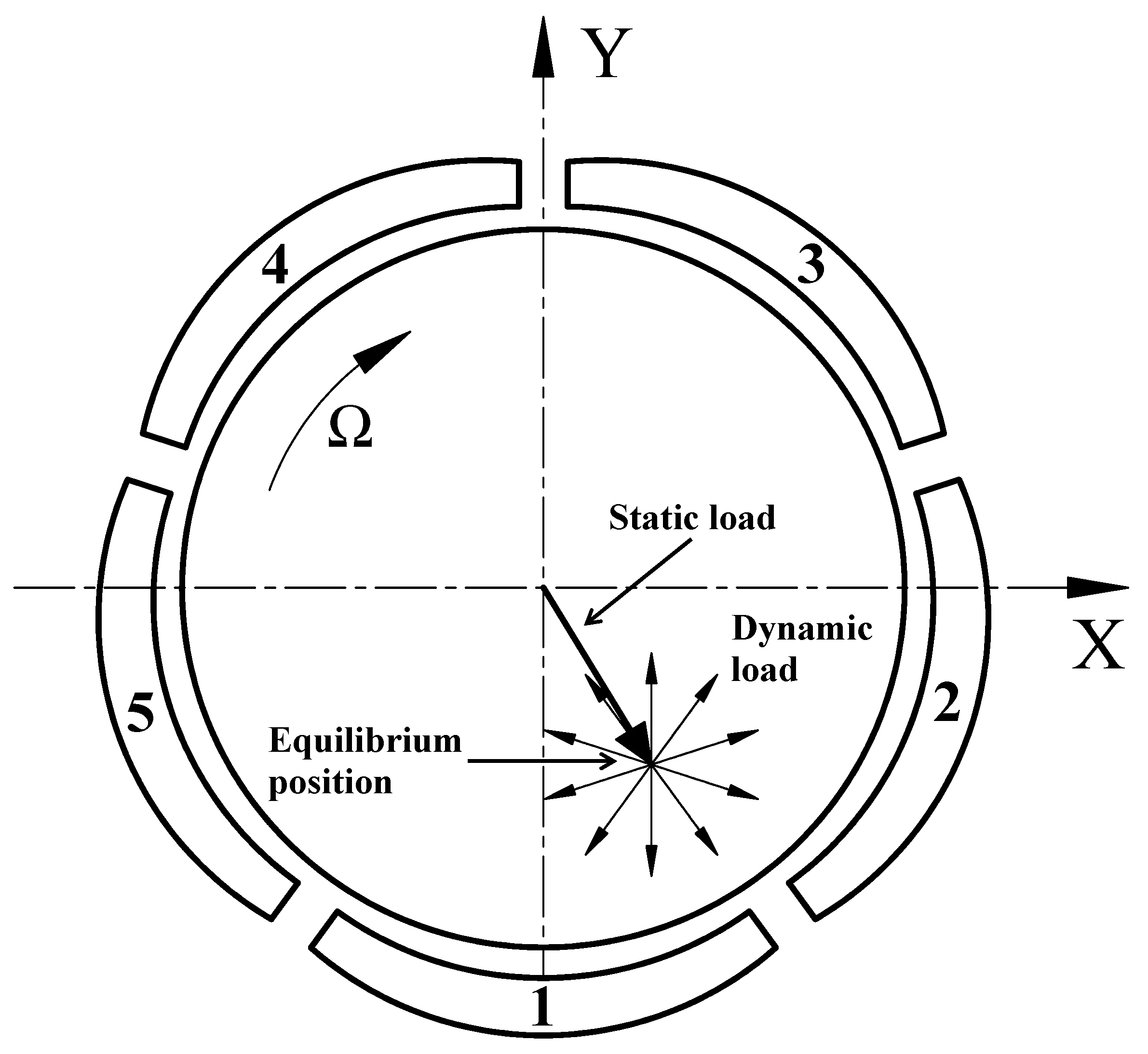
Figure 8 shows the procedure for the pivot stiffness evaluation of pad #1 for the rocker-backed TPJB.
In the beginning of each test, a suitable static load in the vertical direction is applied in the middle of the shaft to make sure that the shaft will be in contact with the pad. This static load and the corresponding position of the pad and the shaft can be used as a reference value. Note that a dry condition was used during the experimental tests to avoid any potential influence of the oil.
In the next step, the applied static load is increased up to 5 kN, with 0.5 kN in each step. The relative displacement between the shaft and the bearing housing in the horizontal and vertical direction is acquired using two proximity probes.
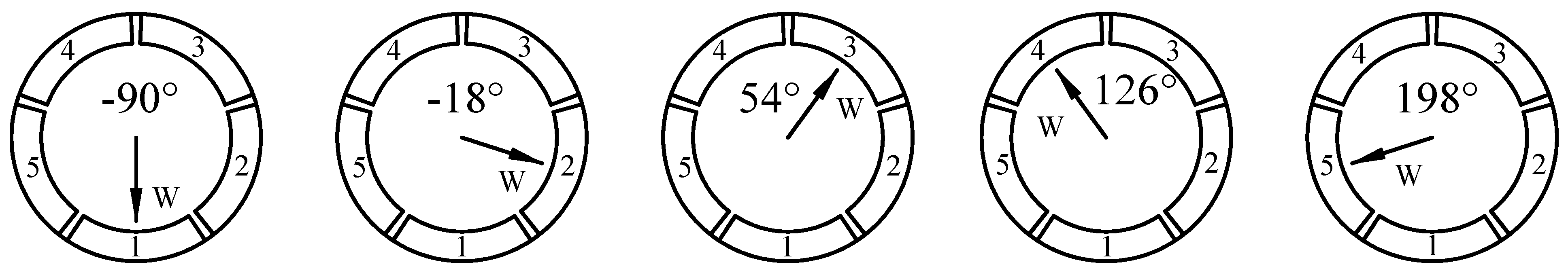
This procedure is repeated for all other pads in LOP configuration by varying the applied static load directions as shown in
Figure 9.
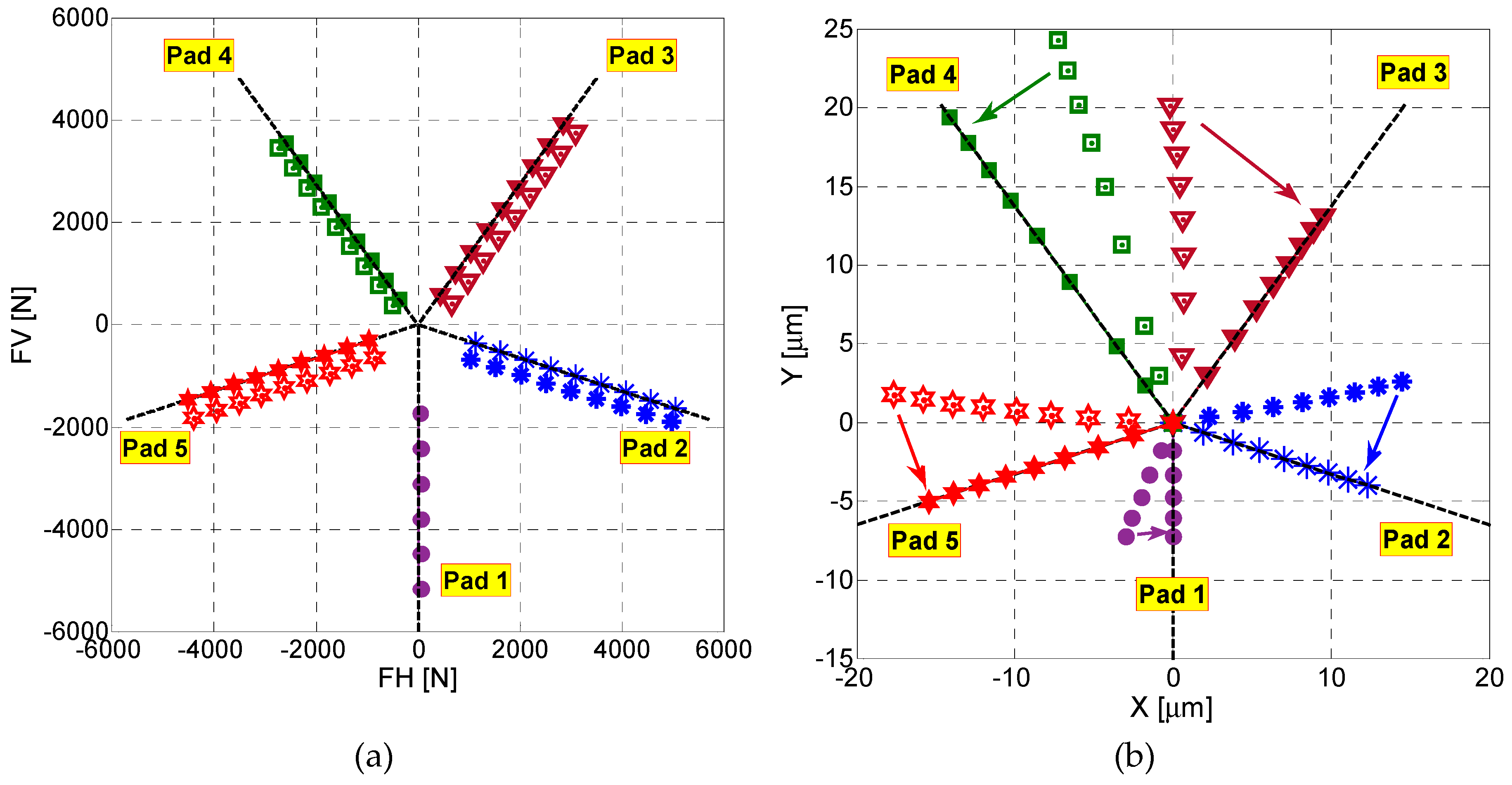
However, due to the flexibility of the system including the bearing and the housing, the measured static load is not exactly in the expected direction, i.e., the applied load directions given by the black dashed lines in
Figure 10a. This effect is more evident for the measured displacement of the shaft as shown in
Figure 10b. Note that the symbols which are no face-color and are placed in an arbitrary position represent the measured static load or displacement. In order to obtain the static load and displacement of the shaft along the expected direction, the measured static load and displacement of each pad are projected to the corresponding black dashed line.
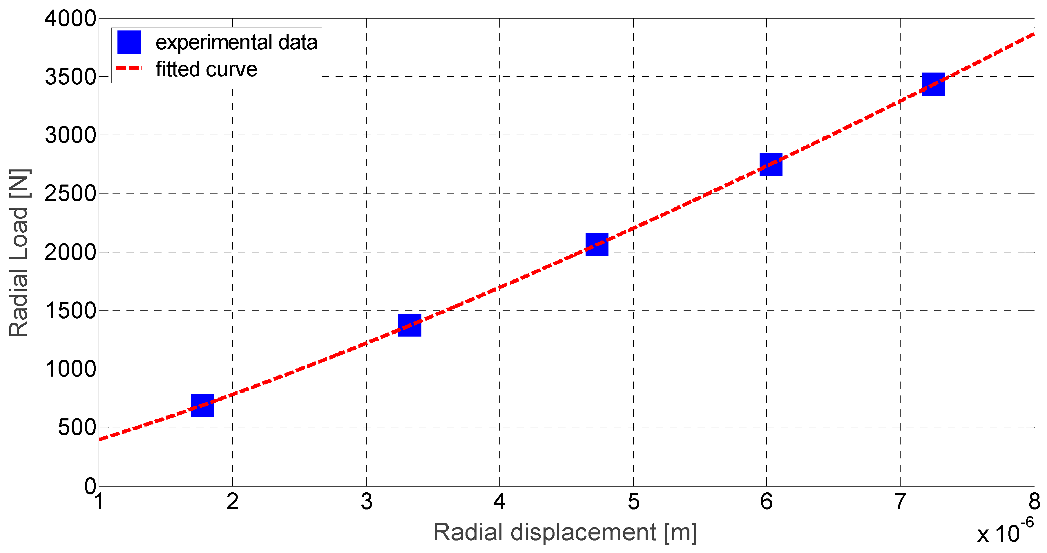
Assuming no deformation on the pad surface, the relative displacement between the shaft and the bearing housing can be considered as the deflection of the pivot in the radial direction.
Figure 11 shows the pivot radial deflection versus the applied static load on the pad #1.
The pivot stiffness can be obtained by:
where
is the pivot radial deflection and
is the increase in the static load.
The same procedure has been also applied for the estimation of the pivot stiffness of the spherical pivot bearing.
Figure 12 shows the pivot stiffness obtained by the Kirk formula and the pivot stiffnesses for all pads obtained by the experimental tests. Pad #3 and pad #4 show unusual stiffness values at low static load. These pads are the upper pads of the tested bearing. Note that, in the beginning of each test, a suitable static load in the radial direction of the corresponding pad is applied in the middle of the shaft to make sure that the shaft will be in contact with the pad. Due to the shaft’s weight, the shaft and corresponding pad are not probably fully in contact each other.
Figure 13 shows the pivot stiffnesses of pad #1 as a function of static load for the two bearings obtained by the mathematical formula and by experiment.
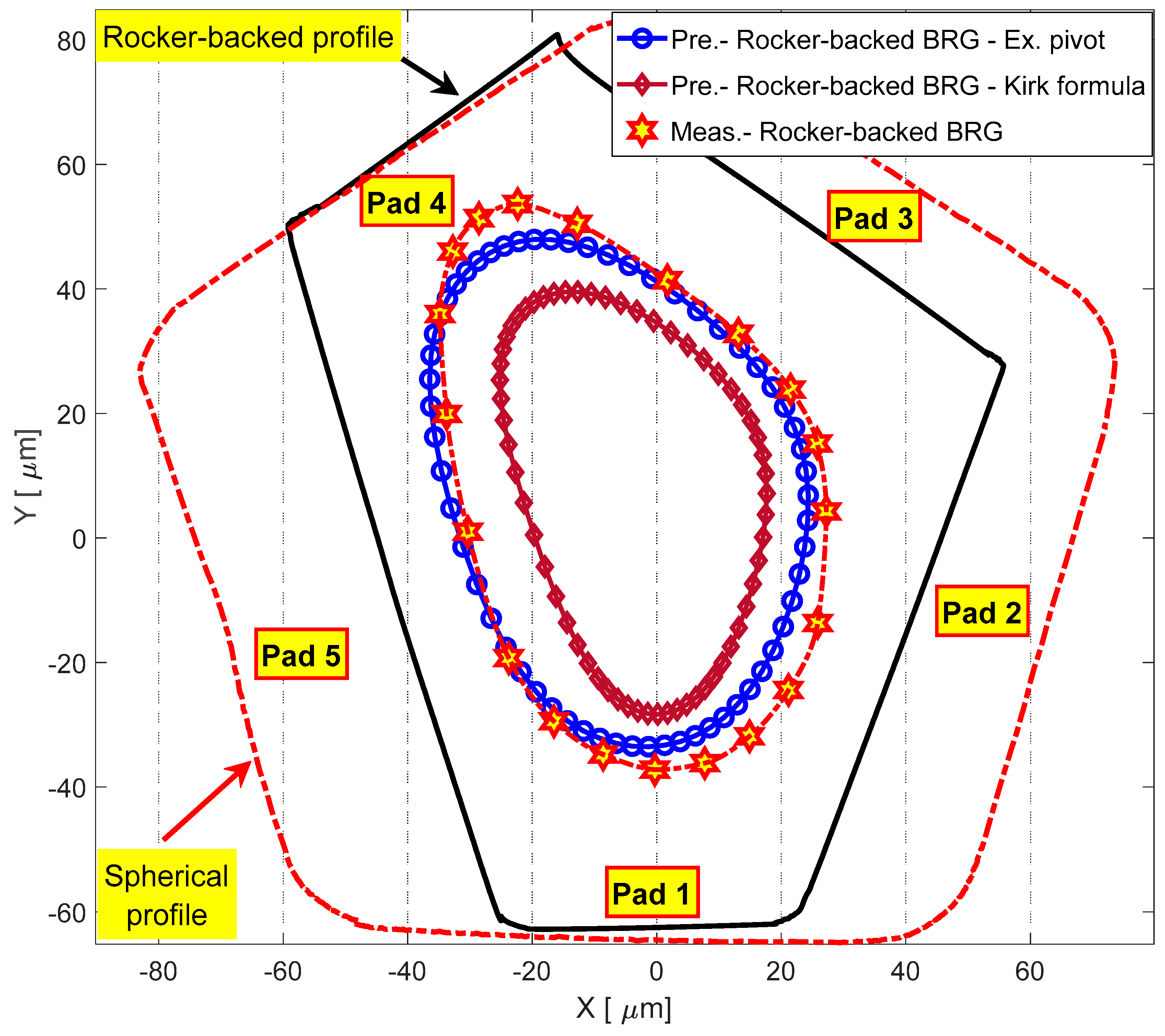
Besides, as shown in
Figure 14, the clearance profile of the rocker-backed bearing has an irregular pentagon shape, especially in correspondence of pad #3 and pad #4. Note that the rocker-backed bearing in this research is a non-nominal bearing, affected by manufacturing error on pads [
37].
It should be noted that the pivot stiffness of the spherical pivot is very small compared to that of the rocker-backed bearing. Besides, the pivot stiffness obtained from the theorical calculation is always overestimated compared to the experiments, especially for the rocker-backed bearing. This problem is probably due to the flexibility of the system including the bearing and the housing during the experiments. This can cause a larger measurement of the shaft displacement than the actual value. Furthermore, the displacement is not exactly in the expected direction (see
Figure 10b).
6. Results and Discussion
As previously mentioned, the influence of the pivot stiffness on the dynamic coefficients as a function of the applied static load and the excitation are analyzed in this paper using the dynamic model of the complete TPJB and the experimental results.
6.1. Center Locus vs. Load Direction
Figure 14 shows the measured pentagonal clearance profile of the rocker-backed (black solid line) and the spherical pivot (red dashed-dotted line) TPJBs. It is interesting to note that whilst the clearance profile of rocker-backed bearing has irregular pentagon shape, the other bearing shows a smooth and more regular pentagonal profile. The unusual pentagonal shape of rocker-backed bearing has been explained in detail in [
36].
It should be noted that except for the parts in correspondence of the pad #1 and pad #4, the clearance profile of the spherical pivot bearing is always larger than that of other bearing. This is due to the fact that the spherical bearing has softer pivot than the rocker-backed bearing, so that the shaft can move further toward the pivot in the spherical bearing approximately of 20 µm.
Within these profiles, twenty positions of the shaft center corresponding to twenty directions of the applied static load (18° for each direction) were plotted. The predicted shaft locus obtained by the model using the Kirk formula for the pivot stiffness was compared to that obtained by using the experimental pivot stiffness and finally compared to the measured shaft locus. Note that these loci were plotted assuming the rotational speed of about 1200 rpm. It can be seen that the journal center loci (both the predicted ones and the measured one) have irregular shapes [
36] but their shapes are quite similar.
It is possible to see from
Figure 14 that the predicted journal center locus of the bearing in which the pivot stiffness is obtained by experimental data (solid blue line with circle markers) is larger than that of the bearing using Kirk formula (solid brown line with diamond markers). This is due to the fact that the pivot stiffness obtained by experimental test is lower than (approximately 2–3 times) that of using the Kirk formula, especially for pad #5. So, for a given static load, the displacement of the pad and the shaft will be greater in the case of soft pivot stiffness.
However, this locus shows very good agreement with measured locus (red dashed-dotted line). There are few discrepancies points between the two loci. This problem probably occurs because the model does not take into account the backlashes and stiffness of the system from the pivot to the proximity probe position. Nevertheless, these discrepancies are quite small, therefore it can be concluded that the results are more accurate if the experimental pivot stiffness is used instead of the stiffness based on the Kirk formula.
6.2. Dynamic Coefficient vs. Static Load
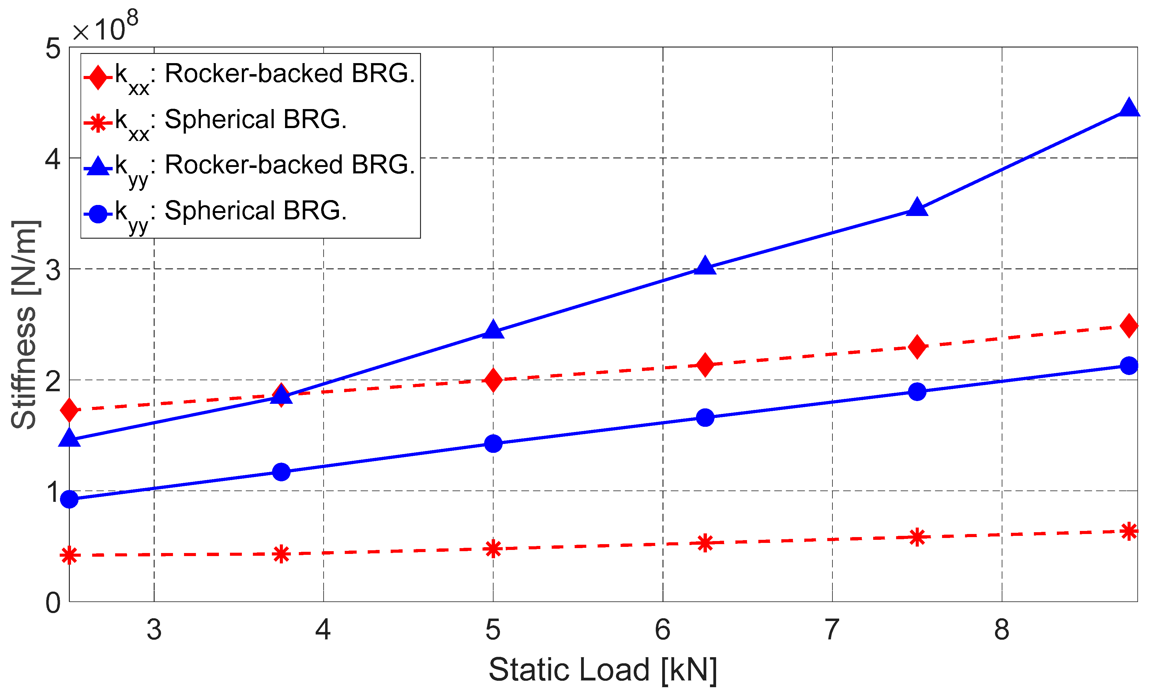
Figure 15 and
Figure 16 show the experimental dynamic stiffness and damping coefficients of two bearings by varying the applied static load, respectively. Only the direct terms of the dynamic coefficients are shown for the sake of brevity. During the tests, the shaft run at the speed of 22 Hz and was excited with a quasi-synchronous force frequency of 25 Hz. The value of static load was increased from 2.5 to 8.75 kN on each bearing. The amplitude of the dynamic force has been limited to the 10% of the static load in order to maintain the shaft close the equilibrium position and satisfy the conditions of linearity.
From
Figure 15, it can be seen that the direct terms of stiffness coefficients,
kxx and
kyy, of both bearings increase more or less linearly with increasing of the static load, in which the stiffness coefficients
kyy show a greater growth than those in the unloaded direction,
kxx. This result is found to be consistent with the [
16]. By increasing the applied static load up to 8.75 kN, the
kyy coefficients of two bearings rise nearly 200% whilst this value is only about 50% for
kxx.
It is possible to observe that the pivot stiffness has a significant impact on the dynamic stiffness coefficients. The direct stiffness coefficients of the bearings having larger pivot stiffness (rocker-backed) are always larger than about 2–3 times those of softer pivot bearings, particularly at high applied static load. This behavior was also concluded in Ref. [
29].
Conversely, it can be seen from
Figure 16 that the effect of the applied static load on the measured direct damping coefficients of two bearings is very small and negligible, except for the damping coefficient of the spherical pivot bearing in the loaded direction,
cyy. In the considered range of applied static load,
cyy of the spherical pivot bearing shows a significant reduction from about 1.01 × 10
5 N-s/m to about 0.724 × 10
5 N-s/m, approximately equal to 150%.
It can be concluded that the more flexible the pad pivot, the lower the dynamic damping coefficients. For instance, the
cyy of the spherical bearing is much smaller than that of the bearing with larger pivot stiffness, i.e., the rocker-backed bearing (about 6 times at high applied static load). This behaviour is quite similar to the finding in [
16]. The same behaviour is also shown for the damping coefficient in the unloaded direction,
cxx. This coefficient of the spherical bearing is always less than, approximately 250%, that of the rocker-backed bearing in the considered applied static loads.
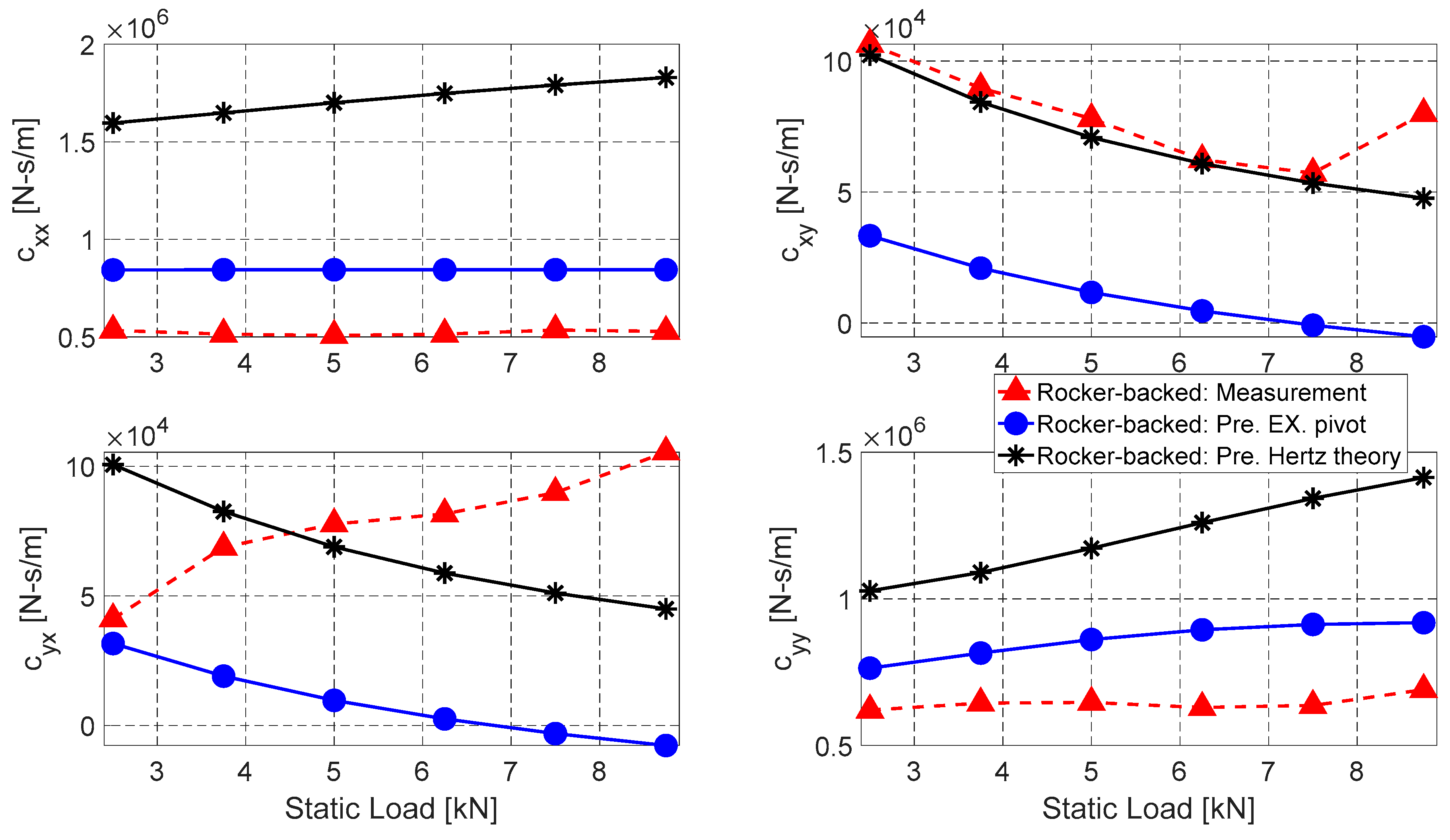
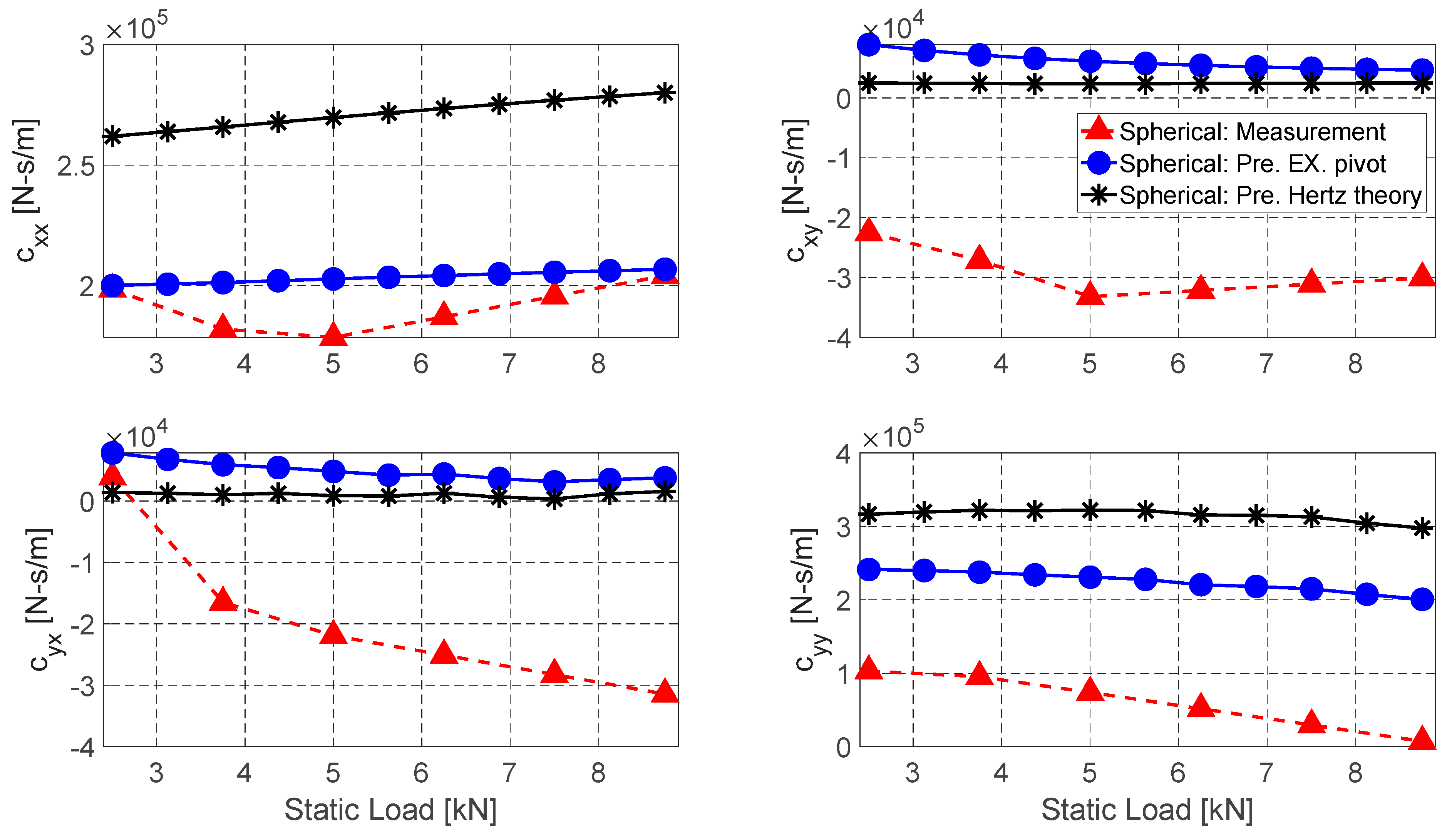
Figure 17 and
Figure 18 show the dynamic coefficients of the rocker-backed TPJB obtained from simulations and experiments, respectively. Besides, the estimation of dynamic coefficients using the Kirk formula and experiment for calculation of pivot stiffness are also presented.
It is worth noting that, the model forecasts very well the increasing tendency of the kxx with the increase of static load if the Hertz contact theory is used. Nevertheless, this model overestimates kxx more or less 80% the experimental values. Conversely, the prediction of kxx value shows very good agreement with measurements if the experimental pivot stiffness is used.
For the stiffness coefficient kyy, if the Kirk formula for the pivot stiffness calculation is introduced in the model, the discrepancy between prediction and measurement is very small, especially with small applied static load. However, this model will underestimate the value of kyy about 10% for the lowest applied static load and 50% for the largest one.
Figure 18 shows the damping coefficients of the rocker-backed TPJB. It can be stated that the model overestimates the damping coefficients approximately 300% for the
cxx and about 200% for the
cyy when the Kirk formula is considered. The model with the experimental pivot stiffness gives better results with a discrepancy between prediction and measurement of 20%. It can be concluded that the pivot flexibility has a significant effect on the estimation of the dynamic coefficient, especially for the damping coefficients.
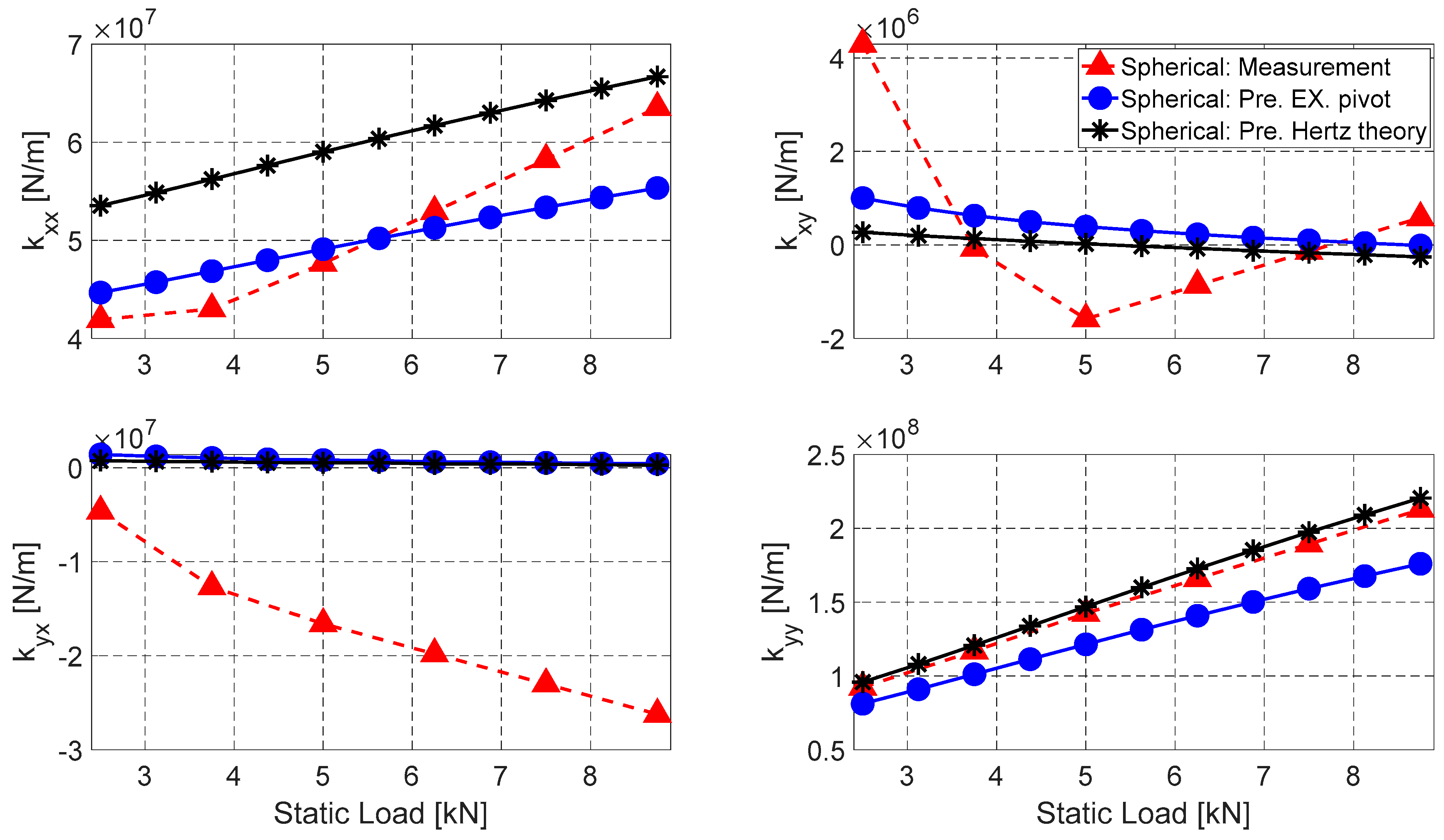
Figure 19 and
Figure 20 show the comparison between the predictions and measurements of the stiffness and damping coefficients for the spherical pivot bearing. It is clearly seen that the results for this bearing and rocker-backed are quite similar. For example, the predicted stiffness coefficient
kxx using the experimental pivot stiffness is very closed to the measured one. It is in contrast to the previous case in which the experimental stiffness provides better results than the Kirk formula.
It is interesting to note that the discrepancy between the measurement and prediction of dynamic coefficients is larger in case of high static load, especially in the loaded direction for
kyy and
cyy as shown in
Figure 17,
Figure 18, and
Figure 20. This fact is probably due to the thermal expansion of the bearing housing and the flexibility of the system. During the experimental tests, whilst the temperature of the oil is maintained around 40 °C by a heat exchanger and temperature controller, the temperature of housing is higher, and approximately equal to 48 °C. This causes the expansion of the mechanical components of the bearing. Besides, the proximity probes installed in the bearing housing labeled as X1A and X1B in
Figure 4 may be directly hit by hot oil exiting from the bearing, due to their arrangement. These remarks and deflection are relevant, because the overall housing expansion may introduce errors in the measurements of relative displacement of the shaft and the pad.
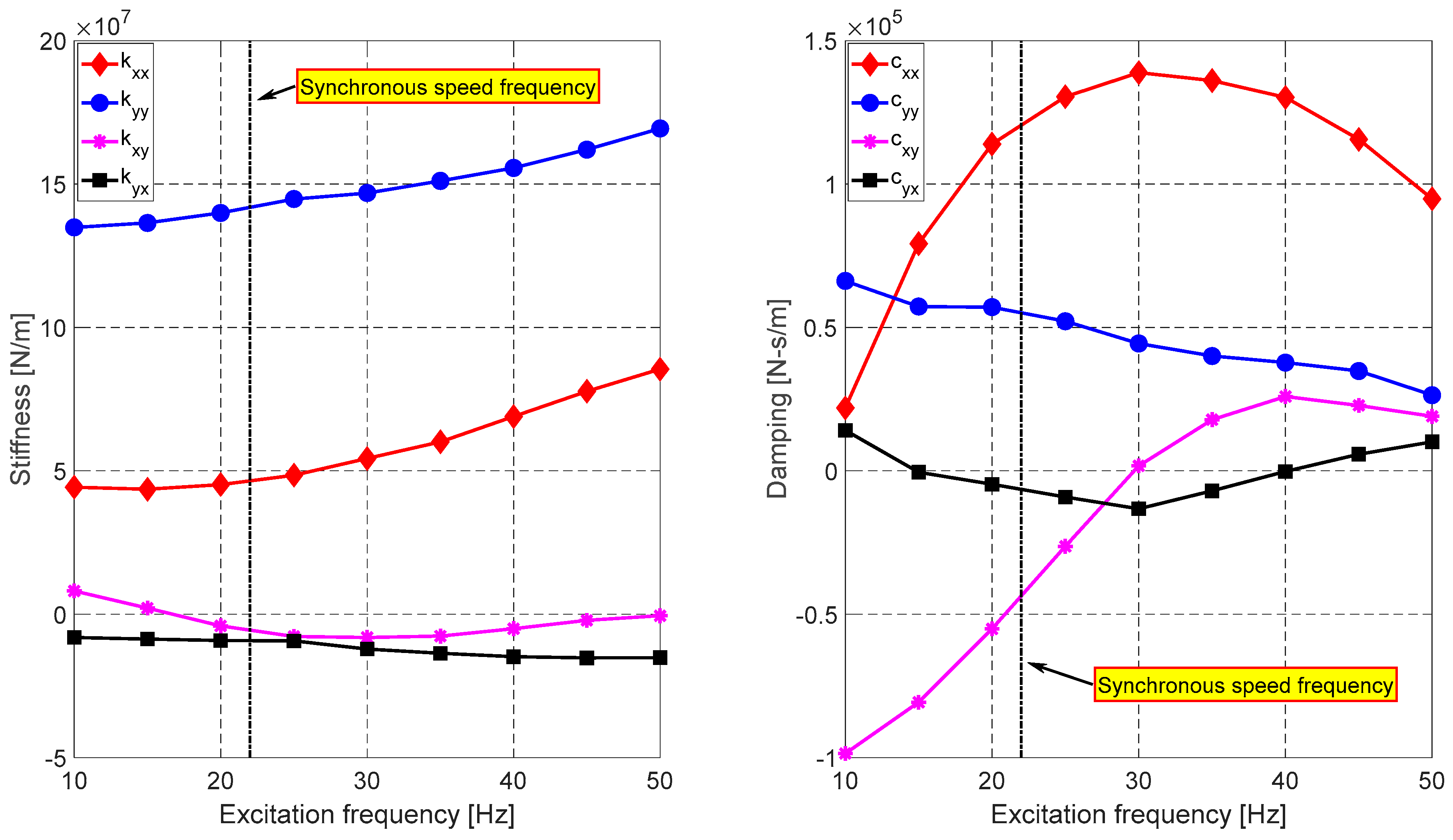
6.3. Dynamic Coefficient vs. Excitation
Figure 21 and
Figure 22 show the oil-film force coefficients of the two tested bearings for a rotational shaft speed of 22 Hz and a static load of 5 kN by increasing the excitation frequency from 10 to 50 Hz, in steps of 5 Hz.
As shown in
Figure 21, the direct dynamic stiffness increases with increasing of excitation frequency especially at high frequencies. The direct stiffness coefficients
kyy are about 20% larger than those identified in the unloaded direction
(kxx). The cross terms of stiffness coefficient are much smaller than the direct terms and are usually neglected. However, they show a stable behavior with the excitation frequency.
The dynamic damping coefficients show the same trend of the stiffness coefficients except for low frequency (less than 25 Hz). It can be concluded that the excitation frequency has smaller effect on the dynamic damping coefficients than the stiffness coefficients. These results are quite consistent with the level of orthotropy as presented in [
11].
For the bearing with the softer pivot stiffness (spherical pivot), the damping coefficients represent an unusual trend in the considered excitation. As can be seen in
Figure 22, the damping coefficient in the unloaded direction
cxx first increases significantly from 0.2 × 10
5 N-s/m (at the excitation of 10 Hz) to about 1.4 × 10
5 N-s/m (at excitation of 30 Hz) and then decreases to approximately 0.9 × 10
5 N-s/m at the highest excitation frequency. The same behavior appears also for the cross-term of the damping coefficient
cxy. Starting from negative value of −1 × 10
5 N-s/m,
cxy reaches a peak of about 0.25 × 10⁵ N-s/m at 40 Hz before slightly reducing to approximately to 0.2 × 10⁵ N-s/m at the highest excitation frequency. This behavior can be due to several technical issues in the system layout and setup such as the position of the load cells, the presence of internal resonances and the setting (amplitude and frequency) of the excitation forces. However, a stable and linearized reduction is shown for the damping coefficient
cyy. Its value decreases about 2 times from more than 0.6 × 10
5 N-s/m to approximately 0.3 × 10
5 N-s/m in the full range of the force frequency.
7. Conclusions
This paper investigated the influence of pivot stiffness on the dynamic behavior of two five-pad TPJB: rocker-backed and spherical pivot bearing. The TEHD model used for the numerical simulation mainly includes the laws of hydrodynamic lubrication, the thermal model of the oil-films, and the flexibility of the pivots. The pivot stiffness of all pads obtained by applying the Kirk formula and experimental measurements are introduced in the model. The experimental procedure for pivot stiffness calculation is also presented. A test rig was used to perform the experimental tests for these two bearings. The results obtained from the numerical simulation and measurement were compared. The following conclusions can be figured out from the experiment measurements and numerical results:
(1) The pivot stiffness of the spherical pivot bearing is about 10 times smaller than that of rocker-backed pad one. Furthermore, the pivot stiffness obtained from theoretical calculation is larger than that of experiments, especially for the rocker-backed bearing.
(2) It is interesting to note that whilst the clearance profile of rocker-backed bearing has an irregular pentagonal shape with shrinking for pad #2 and pad #5 and stretching for pad #4, the spherical pivot bearing shows a more regular pentagon profile. The clearance profile of the spherical pivot bearing is always larger than that of rocker-backed pivot bearing approximately 20 µm, except in correspondence of the pad #1 and pad #4.
(3) The predicted journal center locus of the bearing in which the pivot stiffness is obtained by experimental data is larger than that of the bearing using the theoretical calculation and shows a good correlation with measured locus.
(4) On the one hand, for both bearings, the model correctly predicts the direct term of stiffness coefficients kxx if using the pivot stiffness obtained from the measurement. On the other hand, the model will give good results of the stiffness coefficient kyy, particularly at small applied static load if the Hertz contact theory is used.
(5) It is essential to estimate the pivot stiffness using experimental measurement. For instance, by using the pivot stiffness obtained from the experiment, the discrepancy of cxx between the measurement and the prediction can be reduced significantly from 300% to about 20% in the considered range of the applied static load.
(6) The direct damping coefficients of the spherical bearing are much smaller than those of the rocker-backed bearing when varying the applied static load. Besides, the damping coefficient of the softer pivot bearing in the loaded direction, cyy, shows a remarkable reduction in the considered range of the applied static load.
(7) The pad pivot with more flexibility will lead to the reduction of the dynamic coefficients when varying the dynamic force frequency, especially for the damping coefficients.


