Article

Possibilities of Dry and Lubricated Friction Modification Enabled by Different Ultrashort Laser-Based Surface Structuring Methods

1
Applied Laser and Photonics Group, University of Applied Sciences Aschaffenburg, Würzburger Straße 45, 63743 Aschaffenburg, Germany
2
Laser-Laboratorium Göttingen e.V., Hans-Adolf-Krebs-Weg 1, 37077 Göttingen, Germany
3
Applied Laser Technologies, Ruhr-Universität Bochum, Universitätsstraße 150, 44801 Bochum, Germany
*
Author to whom correspondence should be addressed.
Lubricants 2019, 7(5), 43; https://doi.org/10.3390/lubricants7050043
Submission received: 16 April 2019 / Revised: 10 May 2019 / Accepted: 13 May 2019 / Published: 17 May 2019

Abstract

:
In this contribution we report on the possibilities of dry and lubricated friction modification introduced by different laser surface texturing methods. We compare the potential of Laser-Induced Periodic Surface Structures and Laser Beam Interference Ablation on 100Cr6 steel in a linear reciprocating ball-on-disc configuration using 100Cr6 steel and tungsten carbide balls with load forces between 50 mN and 1000 mN. For dry friction, we find a possibility to reduce the coefficient of friction and we observe a pronounced direction dependency for surfaces fabricated by Laser Beam Interference Ablation. Furthermore, Laser-Induced Periodic Surface Structures result in a load-dependent friction reduction for lubricated linear reciprocating movements. This work helps to identify the modification behaviour of laser generated micro structures with feature sizes of approximately 1 µm and reveals new possibilities for surface engineering.

Graphical Abstract

1. Introduction

Laser surface texturing enables a precise and reliable method to modify surface properties and provides new ways for the design and fabrication of novel surface functionality towards smart surfaces. In this wide field of surface engineering, the controllable modification of friction and wear is of high interest. A recent study reveals that about 23% of the world’s energy consumption and 8120 Mt/year of CO 2 emission are caused by these tribological effects, in turn posing the necessity for wear and friction control [1]. While laser-based surface functionalization has already been intensively studied during the last decade, femtosecond laser technology has recently expedited surface structuring on different length scales to advance tribological properties [2,3,4,5,6,7]. In terms of laser surface texturing, different methods are available to modify the friction behaviour. On the one hand, regular ablation processes using short (pulse duration τ > 10 ps) and ultrashort (pulse duration τ < 10 ps) laser pulses are capable of generating meso- to micro-structures with spatial feature size limitation of the applied laser spot size, typically several tens of micrometers. On the other hand, advanced processing techniques can fabricate surface texturing patterns with feature sizes magnitudes below the applied laser spot size. Out of this research field, we use Laser-Induced Periodic Surface Structures (LIPSS) [8] and Laser Beam Interference Ablation (LBIA) [9] to fabricate periodic linear patterns on solid surfaces with feature sizes of approx. 1 µm. The general difference between LIPSS and LBIA is their origin and the respective profile depth. While LBIA structures are generated by a special interferometer-based optical setup, LIPSS occur in a self organizing process based on the interference of the laser irradiation and Surface Plasmon Polaritons (SPP) [10]. Ultrashort laser-based periodic surface structures can be generated on all kind of solid materials [11,12,13]. Both laser-induced surface morphologies, LIPSS and LBIA, can be generated in a single-step process and provide multiple possibilities to modify different surfaces properties. Possible applications of this laser surface texturing methods involve colorization due to diffraction at the periodic structures [14,15], modification of surface wetting properties [16,17], influence on surface cell growth [18,19], and friction management [20,21,22]. The friction properties of surfaces depend not only on the specific material and several properties of the sliding surface itself, but also on the properties of the counter body, the sliding speed, the environmental conditions, and the nature of any lubricant. Therefore, it is obvious that numerous experimental studies are needed to get fully acquainted with the effects of laser generated periodic surface structures on such tribological properties.
With growing possibilities of flexible methods for laser-based surface functionalization, the question arises, which method leads to the required effects in the field of surface engineering. A line-wise laser surface texturing can be achieved by both methods, LBIA and LIPSS, and they both have the potential to modify friction behaviour. In different tribological test scenarios, LIPSS fabricated surfaces with features in the range of 1 µm and below have shown that it is either possible to increase [23] or to decrease [24] the coefficient of friction (COF). While Gachot et al. [20] report a friction reduction after applying LBIA structures on 100Cr6 while performing a dry linear reciprocating ball-on-disc test, Kasem et al. [25] identify a friction increase on LBIA structures on SAE 1035 steel in a lubricated linear sliding test. Beside the structural modification, the laser-based surface temperature increase, caused by the laser beam absorption, can influence the chemical properties and thus lead to a modification of sliding friction. The important role of the surface chemistry is supported by the studies of Gachot et al. [26] for LBIA and Bonse et al. [7] for LIPSS.
To the best of our knowledge, a direct comparison of the tribological modification behaviour of different laser generated micro structures of approx. 1 µm is not investigated yet. Thus, we use both laser surface texturing methods and demonstrate the possibilities of friction modification and show which method results in which friction behaviour.

2. Materials and Methods

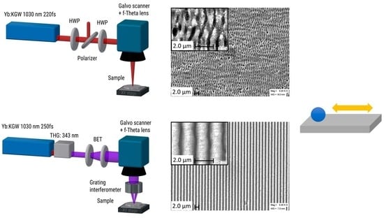
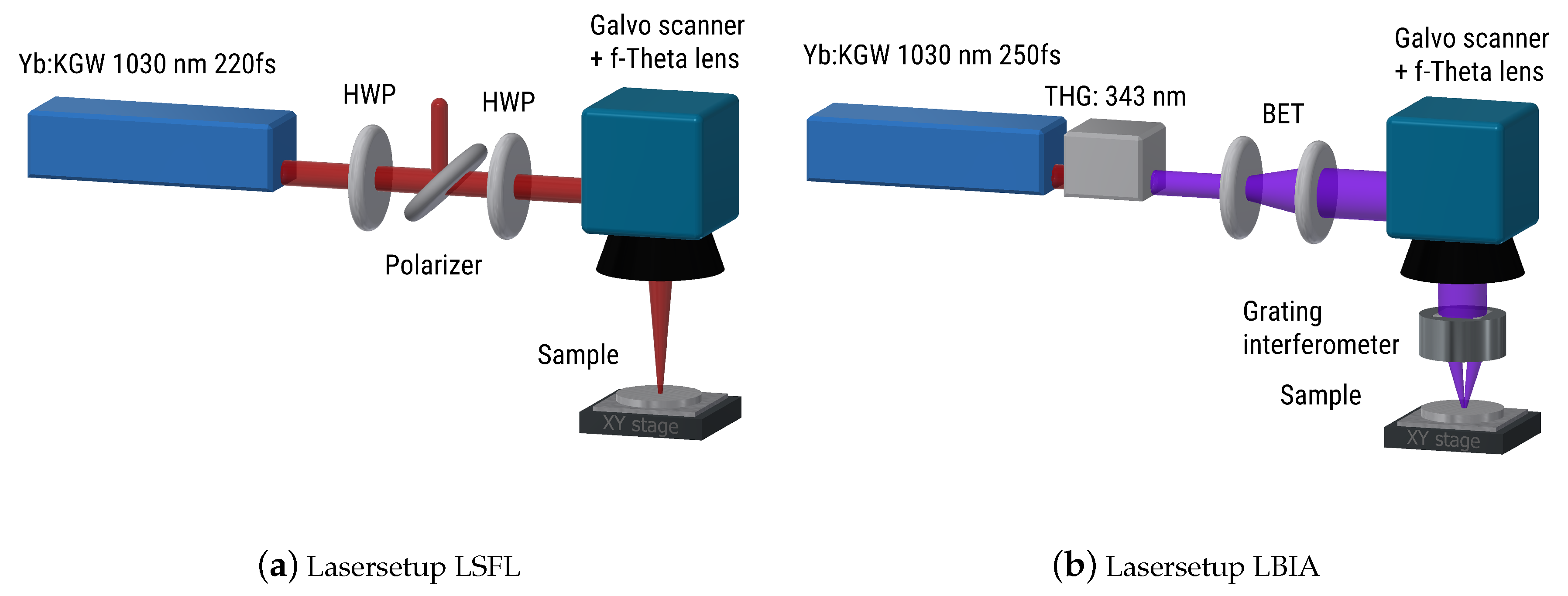
2.1. Laser Surface Texturing

To compare the different laser surface texturing methods, the structures were applied on a chrome steel (100Cr6) substrate with a thickness of 6.6 mm. Before the laser modification is carried out, the base plate was prepared by grinding and polishing with a multi directional polishing using several abrasive grits and afterwards polished with suspensions down to a grain size of 1 µm to achieve a reference surface with a roughness of R a = 14 nm.

2.1.1. LSFL

Generally, LIPSS are categorized into 3 groups, namely low spatial frequency LIPSS (LSFL), high spatial frequency LIPSS (HSFL), and cone-like protrusions (CLP) [8]. In this study, we use LSFL to alter tribological properties. These structures appear upon laser irradiation with linear polarized light. The origin of LSFL is commonly explained by an interference effect of the incident laser light and a surface electro-magnetic wave generated by a laser-induced surface plasmon polarition (SPP) [8]. Due to this origin, LSFL occur with a spatial periodicity in the range of the used laser wavelength and an orientation perpendicular to the polarization of the laser light. Several research groups have shown that LSFL properties like spatial period, orientation, and homogeneity can also be controlled by the applied laser fluence [27,28], pulse to pulse overlap [29], and initial surface roughness of the solid material [30]. For laser surface processing, we used a micro-machining station (MM200 USP, Optec, Frameries, Belgium) equipped with an ultrashort pulsed laser (Pharos 10-600-PP, Light Conversion, Vilnius, Lithuania) having a pulse duration of 220 fs (FWHM) at a repetition rate of 300 kHz. For the generation of the micro- and nano-structures, the fundamental emission wavelength of 1030 nm was utilized. Figure 1a shows the experimental setup for the surface treatment. The energy of the laser was adjusted by an external attenuator based on a rotating wave plate and a polarizer. Using a half wave plate in front of the focusing unit, the linear polarization of the laser beam was rotated orthogonal to the scanning direction. A galvo scanner (RTA AR800, Newson, Dendermonde, Belgium) was used in combination with a telecentric lens (f = 100 mm) to focus the beam onto the sample with a spot diameter of 38 µm (1/e 2 ).

2.1.2. LBIA

Beside the LSFL process, the test disc was structered with high definition periodic line gratings of a single orientation across the whole disc. For the fabrication of these surface structures, laser beam interference ablation (LBIA) was used as shown in Figure 1b, applying a special interferometer-based technique developed at LLG. In this approach, the key component is a so-called grating interferometer [9,31], which creates a well-defined, high quality interference pattern, projected onto the sample surface. This interferometer consists of two transmission phase gratings made of fused silica with their grating lines lined up parallel to each other. In the present experiment, the resulting period of the linear grating-like structures projected onto the sample surface was 1.5 µm. A fast scanning system (intelliSCANde 14, SCANLAB GmbH, Puchheim, Germany) with a focusing optic is applied to ablate arbitrary patterns on the sample, while allowing full coverage of the entire processed area with a highly deterministic periodic structure. The modulation depth of the resulting relief structure can be varied within a wide range by adjusting the laser energy and the scanning speed. In the present study, the modulation depth was adjusted to approx. 1.6 µm on the surface of the test discs, in order to achieve an aspect ratio of roughly 1:1. The Yb:KGW femtosecond laser source (Pharos 20-1000-PP, Light Conversion, Vilnius, Lithuania) used for the ablation process provides pulses at 300 kHz with a duration of 250 fs at a wavelength of 1030 nm. For the presented investigation the laser system was equipped with a third harmonics module which converted the wavelength to 343 nm. Those ultrashort laser pulses are focused to approx. 20 µm and scanned across the sample area.

2.2. Surface Analysis

The generated surface structures were analyzed using atomic force microscopy (XE-150, Park Systems, Suwon, Korea) and scanning electron microscopy (EVO MA10,Carl Zeiss Microscopy GmbH, Jena, Germany). The AFM measurements were used to obtain the 3D surface topology of the different structures in order to determine the depth of the structures. The AFM was operated in non-contact mode using a cantilever with high aspect ratio (>5:1) silicon tip (NANOSENSORS AR5-NCHR, NanoWorld AG, Neuchatel, Switzerland). Images with 512 × 512 pixels were recorded at a scan rate of 0.2 lines per second and a scan size of 10 × 10 µm. The SEM images with 1024 × 768 pixels were taken at a high voltage of 18–20 kV, a filament current of 2.39–2.44 A, and a probe current of 3–20 pA. The working distance was 5–8 mm and the minimum pixel size 5.86 nm.

2.3. Tribological Analysis

The measurement of the COF was performed in a ball-on-disc (BoD) setup. We used a universal mechanical tester (UMT TriboLab, Bruker Corporation, Billerica, MA, USA) to perform the tribological evaluation. The system is equipped with a linear drive allowing linear reciprocating translation and a second drive unit to apply a specific load of the ball on the base plate. The used force sensor allows measuring the load FL and the lateral force FX up to 5 N. The resulting COF is calculated by FX/FL. We measured the friction behaviour between the 100Cr6 steel substrate and either tribometer balls of chrome steel (100Cr6) or tungsten carbide, both with a diameter of 6.3 mm. The resulting wear on the substrate is captured using laser scanning microscopy (VK-X200, KEYENCE DEUTSCHLAND GmbH, Neu-Isenburg, Germany). Therefore, the track width (point-to point) of the wear tracks on the substrate is measured by a threefold rating. Beside the dry friction test, the COF is measured in a lubricated environment by a thin film of engine oil (5W40).
Due to the elastic deformation of the 100Cr6 steel and tungsten carbide balls, different contact areas appear. Using a Hertzian deformation model of a sphere in contact with a flat sample, the diameter of the contact area is calculated in Table 1.
An overview of the applied tribologcial test conditions is given in Table 2 for both sliding regimes, dry and under lubrication. Due to the decreased wear generation using lubrication, higher load forces and numbers of test cycles are possible.

3. Results and Discussion

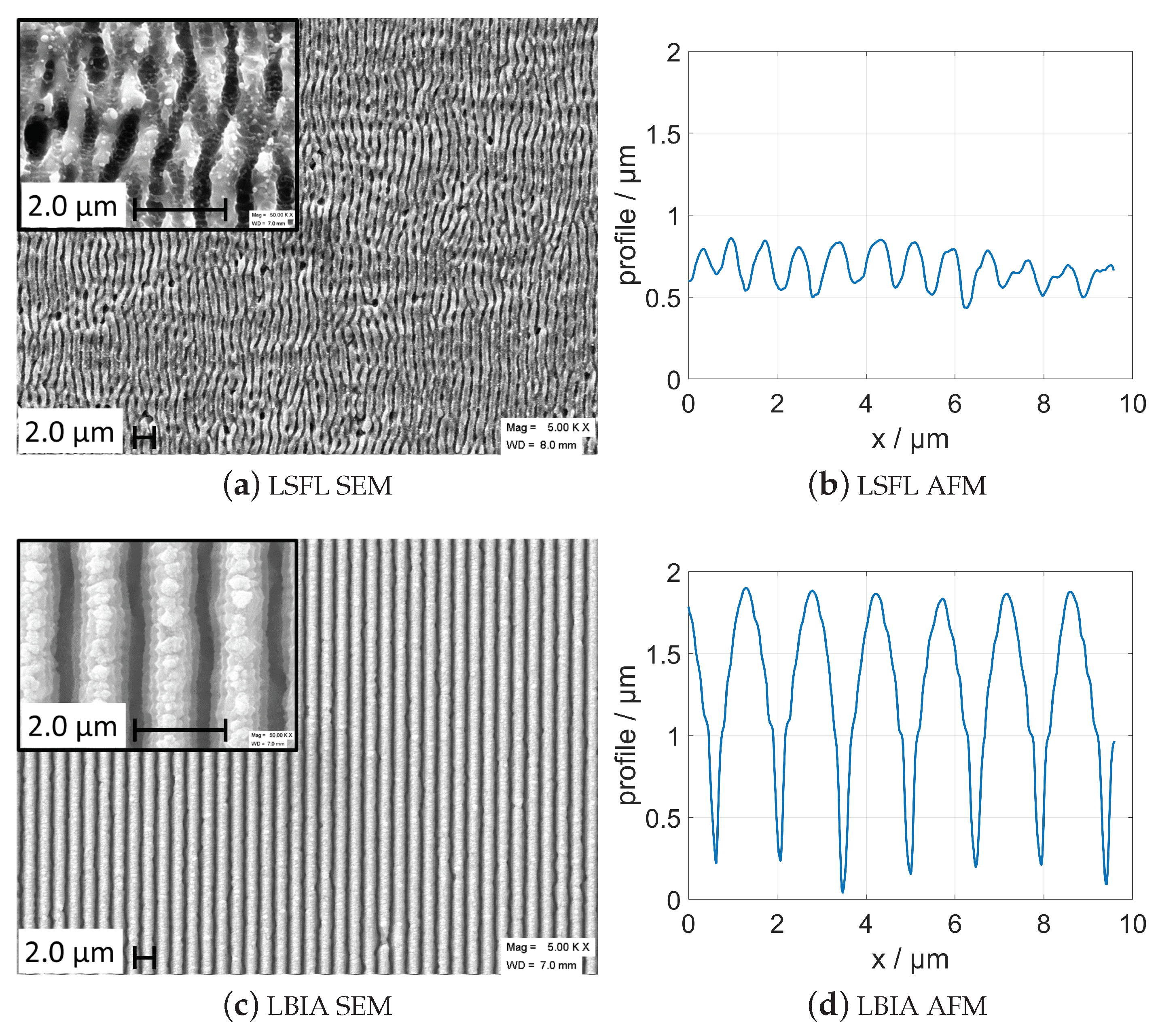
3.1. Laser Surface Texturing

In the first step, the required laser parameters for continuous surface texturing on 100Cr6 steel are determined. For the LSFL process, the laser fluence and the pulse overlap are optimized to generate a homogeneous LSFL-covered surface. Figure 2a shows the SEM image were the fluence is set to 0.5 J/cm 2 and the pulse to pulse overlap for subsequent laser pulses and scanning lines is 80%. The use of the laser wavelength of 1030 nm and a linear polarization of the laser light results in a linear pattern with an average spatial periodicity of ≈900 nm. Due to the slightly smaller spatial period with respect to the laser wavelength and the perpendicular appearance of the structures, these LIPSS are identified as LSFL. The periodic structures show a uniform periodicity and a straight vertical course. The topographical shape is shown in Figure 2b by a AFM measurement. The height profile shows a homogeneous modulation depth of (201 ± 32) nm.
For the LBIA process the laser parameters and the scanning overlapp of the focused beam were adjusted to produce lines at a depth of approx. 1.6 to 1.7 µm. Due to the projection of lines of the grating interferometer onto the sample surface, the resulting surface structures are highly regular with a strict spatial periodicity of 1.5 µm. The resulting images of the SEM mesurements as well as the measured structural depth from AFM measurement is shown in Figure 2c,d.
The comparision between the LSFL and LBIA structures in Figure 2 shows that the LBIA structures show a higher uniformity and a much more pronounced orientation of the lines. The LSFL structures occur with a 0.6 times smaller spatial periodicity, while the modulation depth of the LBIA structures was about 8 times larger.

3.2. Friction Measurement

In the following diagrams (Figure 3 and Figures 5–7), the resulting COF is shown for the reference surface (black solid curve), the LBIA-structured surfaces (red curves) and the LSFL-covered surfaces (blue curves). Furthermore, the relation between the periodic surface structures and the sliding direction is indicated by the line style. For a sliding direction along the periodic grooves, dotted lines and the index “−0” are used. Dashed lines represent a perpendicular sliding movement which is also indicated by the added index “−90”. The presented COF values are calcuated by the average of 50 s of steady measurement of the applied force and the induced lateral force. The shown error bars in Figure 3 and Figures 5–7 represent the deviation of the calculated COF for a time range of 50 s.

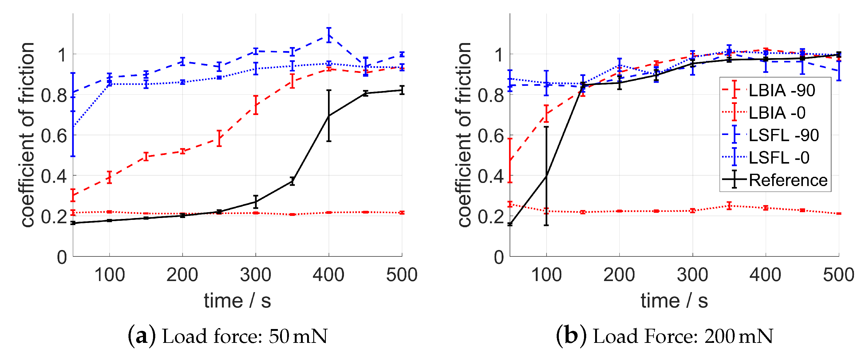
3.2.1. Dry Test 100Cr6 on 100Cr6

Figure 3 shows the results of the tribological linear reciprocating ball-on-disc evaluation using a 100Cr6 disc and a 100Cr6 triboball for 50 mN and 200 mN load force. The oscillating sliding test is performed for 500 s with a stroke of 2 mm and a frequency of 1 Hz which corresponds a total track distance of 2000 mm. On the reference surface, the COF starts at values below 0.2 and rises slightly with ongoing runtime. After 300 s, the COF rises strongly and approaches a steady state after 450 s with a COF of 0.8. This COF incline can be described by a damage of the natural superficial oxide layer on the surface [32]. With increasing load force, the COF incline starts already within the first 50 s and after a total run time of 150 s, the steady state is nearly reached at a COF of approx. 0.9–1. Surfaces covered by LSFL reveal a comparable high COF directly at the beginning of the linear reciprocating movement. For the movement parallel to the LSFL orientation, the COF starts with a value of 0.65 and increases with time to a value of approx. 0.93. The perpendicular movement on LSFL show higher values for the COF over the entire test duration, starting at 0.81 and with a steady state value of 1. Contrary to the LSFL-covered surface, the LBIA structures introduce only a small COF increase at the beginning of the tribological test. For a perpendicular movement, the COF starts with 0.3 and 0.5 for 50 mN and 200 mN respectively. The break-in effect, which is defined as the initial COF modification by ongoing test duration, is visible for both load forces: For 50 mN the steady state is reached after 400 s and for 200 mN after 250 s. While LSFL-0, LSFL-90, and LBIA-90 result in a COF increase over the entire linear reciprocating ball-on-disc evaluation for both load forces, LBIA structures combined with a parallel movement (LBIA-0) result in a stable COF value at approx. 0.2 for both 50 mN and 200 mN.
The differences of the coefficient of friction for LSFL- and LBIA-covered surfaces are also visible in the microscopy image after the linear reciprocating ball-on-disc evaluation. The high COF value for laser surface texturing using LSFL implies a strong interaction between the disc and the triboball. Figure 4a shows the borderline between the initial LSFL and the friction affected area using a parallel movement and a load force of 50 mN. In the sliding track, LSFL vanished completely and big artefacts caused by a strong material adhesion and galling [33] are visible. As indicated by the small COF in Figure 3a, the wear on the LBIA surface after the parallel movement in Figure 4b is less pronounced. The wear track is visible but the laser surface texturing is still present. Along the complete stroke, no artefacts of material adhesion and galling are visible.

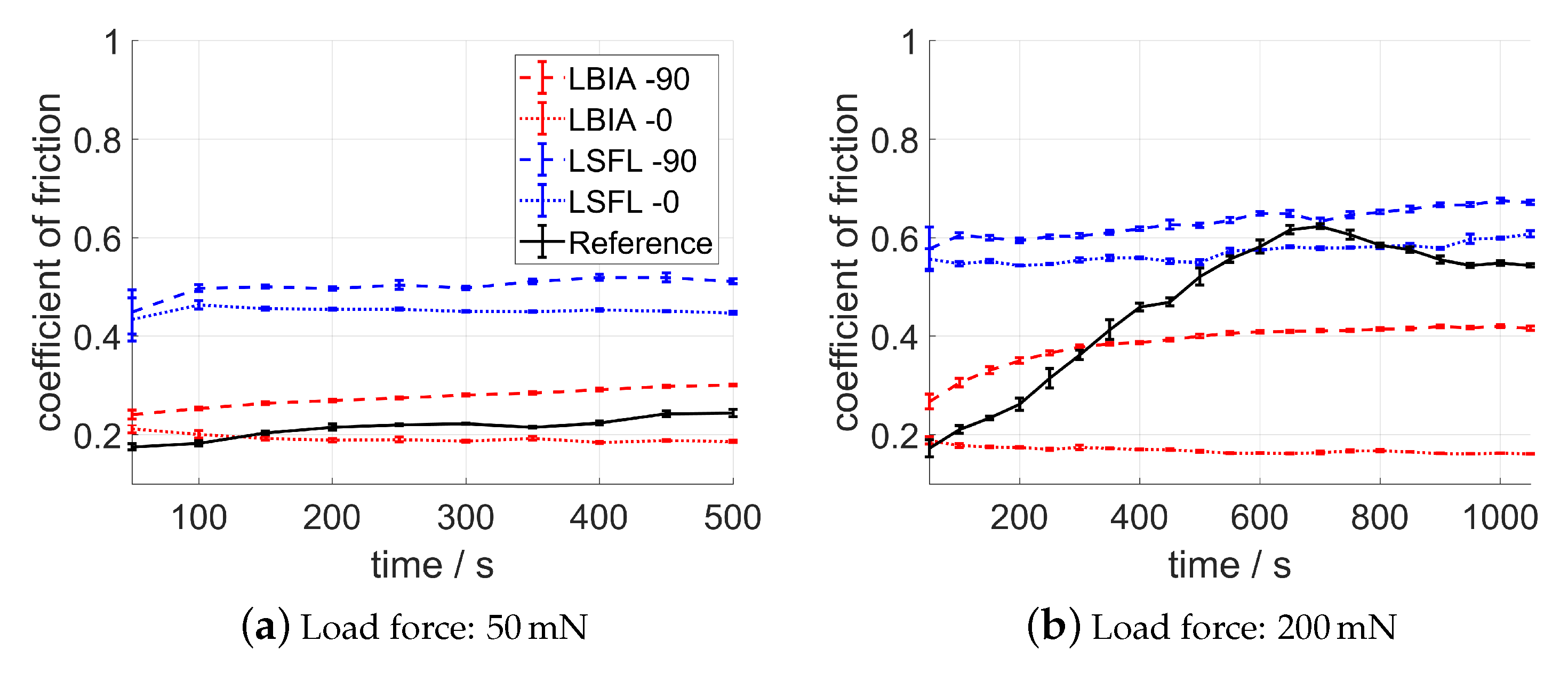
3.2.2. Dry Test Tungsten Carbide on 100Cr6

The results of the tribological linear reciprocating ball-on-disc evaluation using a 100Cr6 disc and a tungsten carbide triboball for 50 mN and 200 mN load force are shown in Figure 5. The general comparison to the pairing 100Cr6/100Cr6 shows that the coefficient of friction is lower for all tested surfaces. On the polished reference surface, the coefficient of friction is 0.18 in the beginning and rises slightly up to 0.25 for a load force of 50 mN. With increasing load (Figure 5b), the COF increases to values of 0.55 at the end of the evaluation time of 500 s. The LSFL-structured surfaces lead to a COF increase over the entire evaluation time. For parallel and perpendicular movements, the COF starts at 0.45 and stays nearly constant for parallel sliding direction. The COF for the perpendicular movement on LSFL is higher (c.f. dry test 100Cr6/100Cr6) and rises to a steady state at 0.5. This behaviour also appears for the higher load force of 200 mN. The COF for LSFL-0 and LSFL-90 is initially 0.57 and increases to 0.6 for a parallel movement and to 0.68 for a perpendicular sliding direction. The LBIA surface introduce a small COF increase at the beginning of the test for both test loads. Using a perpendicular movement, the COF shows a time-based increase and runs from 0.24 to 0.3 for 50 mN and from 0.27 to 0.41 for 200 mN. Contrary to this behaviour, the parallel movement on the LBIA surface reveals a slight COF decrease with ongoing evaluation time. For 50 mN the COF decreases from 0.21 to 0.19. Using a load force of 200 mN, the COF reduces from 0.19 to 0.16.

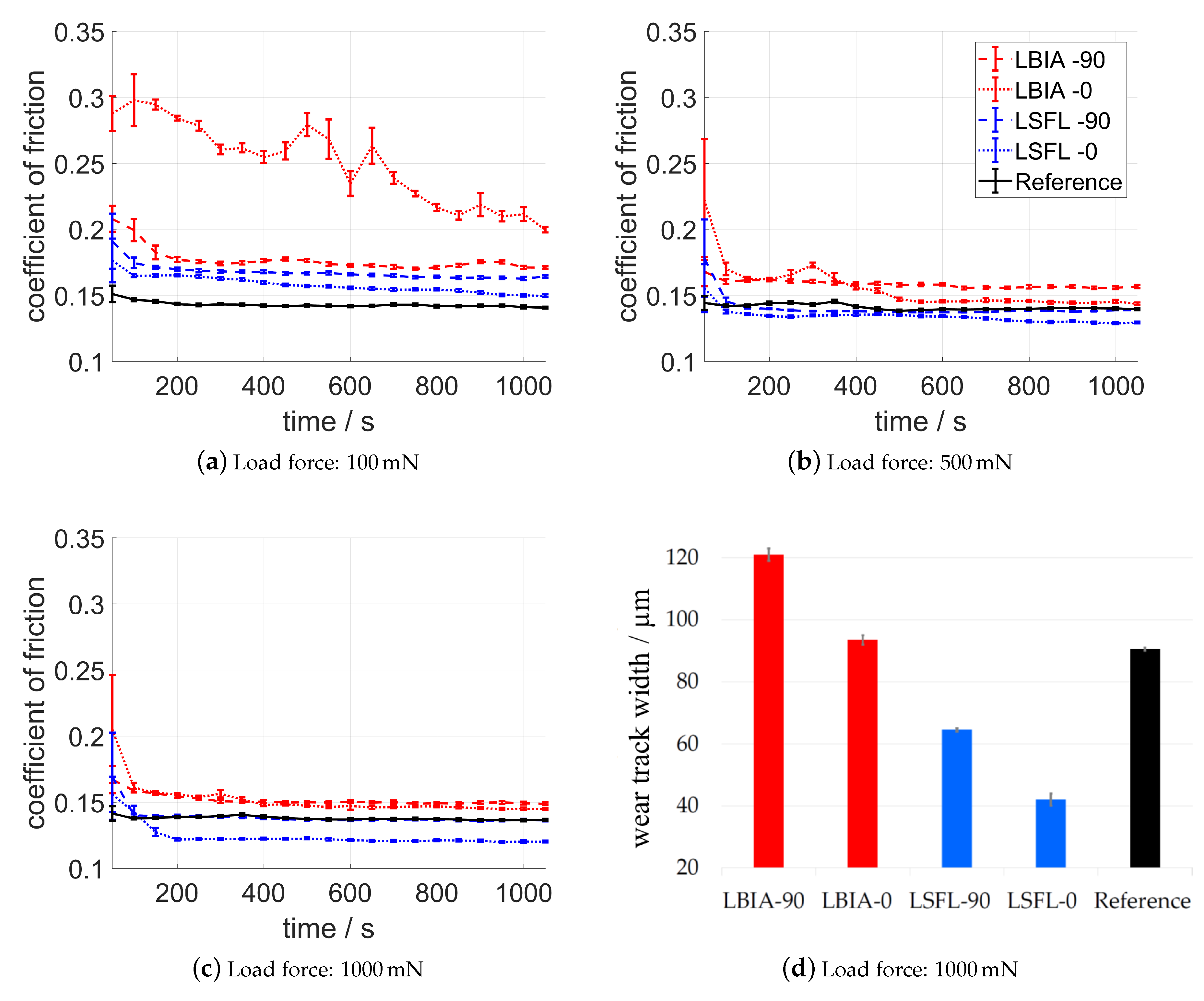
3.2.3. Lubricated Test 100Cr6 on 100Cr6

In Figure 6, the results for the lubricated tribology test using the 100Cr6 triboball are shown. Due to the lubricated friction and the adjunctive COF and wear decrease, it is possible to increase the maximum applied load to 1000 mN and the test duration to 1000 s. The oscillating sliding test is performed with a stroke of 2 mm and a frequency of 1 Hz which corresponds a total track distance of 4000 mm. Figure 6a–c shows the coefficient of friction in a 100Cr6/100Cr6 configuration for 100 mN, 500 mN, and 1000 mN respectively. The COF measurement on the polished reference surface reveals no remarkable influence of the applied load force and is stable at 0.14–0.15. For all lubricated test configurations, the initial COF changes with ongoing test duration. Contrary to the dry friction evaluation, this observed break-in effect causes a COF reduction after a specific test duration. While the applied load does not effect the COF on the reference surface, both LSFL- and LBIA-structured surfaces reveal a load dependency for the COF. For a test load of 100 mN, laser surface structuring in general introduce a COF increase. Figure 6a reveals that the highest friction is measured on the LBIA surface for a parallel movement. Starting with a COF of 0.29, the ongoing COF decrease within the test duration implies that the break-in effect, i.e., the ongoing change of the COF until it reaches a steady state, is not finished after 1000 s. For 100 mN, the influence of sliding direction is well pronounced for both LBIA and LSFL surfaces. The initial friction of LBIA-90 is 0.2 and reduces to 0.18. The COF for LSFL-covered surfaces is smaller; for a perpendicular sliding direction it starts at 0.19 and reduces to 0.16 and for a parallel movement it starts with a COF of 0.17 and decline to 0.15. With increasing load force, a remarkable effect is observed, the COF reduces on structured surfaces with increasing load force. For 500 mN and 1000 mN the COF for a parallel movement is smaller on both LBIA- and LSFL-covered surfaces. At the end of the observation time, LBIA surfaces still show an increased COF. According to the reference COF, perpendicular sliding direction on LBIA introduces a 12% increase and parallel movement a 3% increase. LSFL reveal the potential to decrease the COF. While the perpendicular movement on LSFL introduces a COF reduction of only 1%, the friction reduction for parallel movement is 7%. Figure 6c shows that increasing the load force to 1000 mN lead to a further friction reduction for parallel movement on LSFL. After the break-in (approx. 200 s), a stable COF reduction of 12% according to the reference surface can be measured. On the LBIA-structured surface, a small COF increase of 9% remains for perpendicular movement and 6% for parallel movement.
Figure 6d shows the width of the generated wear track on the disc’s surface for the lubricated oscillating sliding test with a applied load of 1000 mN. On laser textured surfaces, the wear track width decreases according to the measured COF values, i.e., the highest COF (LBIA-90) leads to the highest wear width and the lowest COF (LSFL-0) leads to the lowest wear track width. The comparison of the magnitude of the wear track width and the contact diameter between the ball and the flat surface shows a pronounced difference. On LBIA-90 the wear track is more than double for a load force of 1000 mN (cf. Table 1). A friction-based temperature rise in the contact zone could lead to elastic–plastic deformation of the involved interfaces [34,35]. It is worthwhile to mention that the similar COF of the reference and the LSFL-90 surface does not result in a similar wear track width. The laser processing generates a thin oxidized passivation layer on the surface [32], which protects the surface against friction-induced damage.

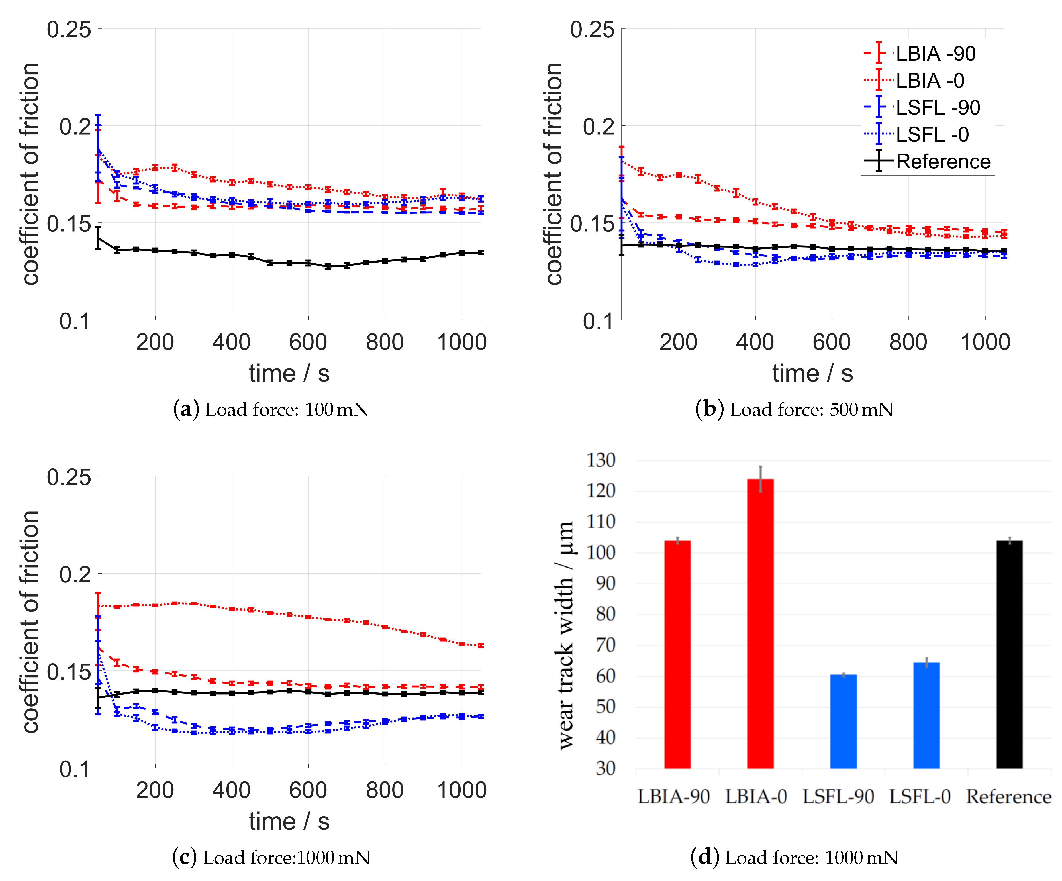
3.2.4. Lubricated Test Tungsten Carbide on 100Cr6

Figure 7 summarizes the results of the lubricated tribological linear reciprocating ball-on-disc evaluation using a 100Cr6 disc and a tungsten carbide triboball for 100 mN, 500 mN, and 1000 mN load force. Comparable to the results for lubricated 100Cr6/100Cr6 experiments, the COF of the polished reference surface remains nearly unaffected over the test duration. After a short break-in, the COF is stable between 0.13 and 0.14. The slight increase of the COF with increasing load force is attributed to the decreasing film thickness of the lubricant between the WC ball and the polished disc surface [36]. For the smallest investigated load of 100 mN, all laser textured surfaces introduce a COF larger (15%–20%) than the reference surface. With increasing load, both laser textured surfaces are characterized by decreasing COF. According to the research of Ben-David et al. [37] or Ma et al. [38], the nonlinear increase of the degree of surface contact with increasing contact pressure of a rough surface is responsible for this effect. Again, the COF of LBIA surfaces stays above the reference surface. LSFL-covered surfaces introduce a COF decrease for an applied load of 500 mN and 1000 mN (c.f. Figure 7b,c). In both load cases, the direction dependency on LSFL vanishes and a COF reduction of 2% and 9% for 500 mN and 1000 mN can be measured, respectively. The COF for LBIA-0 increases with increasing load force. This behaviour is in contrast to all other lasers structures surfaces in this study, and can be expalined by numerical simulations by Zhu and Wang [34,39], who studied the lubricant film thickness between a tribo ball and a surface with linear surface modulations similiar to those of the LBIA surface. Sliding along the linear features effects a decrease of the film thickness of the lubricant. On the cusps of the LBIA features, however, little or no lubricant film will be spread. Due to the steady contact during sliding, the lubricant locally leaks out leading to an increased friction. The sliding movement transverse to the line shaped structures (LBIA-90) provides more resitance to the lubricant, causing an increase of the average lubrication film thickness between the ball and the rough surface [34,39].
The increased and decreased friction caused by LBIA and LSFL also affects the generated wear track width shown in in Figure 7d. As mentioned above, the increased friction on LBIA leads to a temperature increase and thus to an elastic–plastic surface deformation. Figure 7d also reveals that the COF reduction on LSFL-covered surfaces leads to a wear reduction on the 100Cr6 disc. According to the reference surface, a reduction wear track width of up to 42% is possible using LSFL and parallel movement.

4. Conclusions

This research work focused on femtosecond laser surface texturing on 100Cr6 steel using two different methods for the generation of periodic surface structures. Both methods produce a linear pattern on the surface. The LSFL approach fabricates a periodic surface pattern with a spatial period of ≈900 nm and a modulation depth of ≈200 nm. Using the LBIA technique, a surface modulation with a period of 1.5 µm and a depth of ≈1.6 µm is generated. To compare the potential of friction modification, a tribological linear reciprocating ball-on-disc evaluation is performed using 100Cr6 steel and tungsten carbide (WC) triboballs. The effects of sliding direction and load force are evaluated against a polished reference surface for dry and lubricated conditions. Table 3 summarizes the observed effects with respect to the reference surface, highlighting the potential fields of applications for LBIA and LSFL.
Although LBIA and LSFL generate surface structures with similar periodicity, the overall tribological behaviours are different. For the tribological analysis without lubrication, LSFL causes a COF increase for both the 100Cr6/100Cr6 and 100Cr6/tungsten carbide combinations. The perpendicular movement on LBIA structures generates COF comparable to the reference surface. Parallel sliding direction on LBIA surfaces decreases the friction remarkably for both 100Cr6 and tungsten carbide triboballs. Comparing the lubricated friction behaviour of LSFL and LBIA shows the possibility of COF reduction using LSFL-covered surfaces up to 12% for 100Cr6/100Cr6 and up to 9% for 100Cr6/tungsten carbide configuration. An additional benefit of LSFL-covered surfaces in the introduced test scenario is the reduced wear track width. In contrast to the COF reduction introduced by LSFL for lubricated friction, LBIA lead to a COF increase for both 100Cr6 and tungsten carbide triboalls under lubricated test conditions.

Author Contributions

Conceptualization, S.R. and K.B.; Methodology, S.R., K.B., S.S. and J.-H.K.-W.; Software, S.R.; Validation, K.B. and F.K.; Formal analysis, S.R.; Investigation, S.R., K.B. and F.K.; Resources, P.S. and R.H.; Writing—original draft preparation, S.R., K.B. and F.K.; Writing—review and editing, S.R., F.K., P.S., J.-H.K.-W., C.E. and R.H.; Visualization, S.R., K.B. and F.K.; Supervision, P.S., C.E. and R.H.; Funding acquisition, P.S. and R.H.

Funding

This research received no external funding.

Conflicts of Interest

The authors declare no conflict of interest.

References

  1. Holmberg, K.; Erdemir, A. Influence of tribology on global energy consumption, costs and emissions. Friction 2017, 5, 263–284. [Google Scholar] [CrossRef]
  2. Ancona, A.; Carbone, G.; Scaraggi, M.; Mezzapesa, F.P.; Sorgente, D.; Lugarà, P.M. Laser surface micro-texturing to enhance the frictional behavior of lubricated steel. In Proceedings of the SPIE Laser-Based Micro- and Nanoprocessing VIII, San Francisco, CA, USA, 1–6 February 2014; Volume 8968, p. 896806. [Google Scholar]
  3. Scaraggi, M.; Mezzapesa, F.P.; Carbone, G.; Ancona, A.; Tricarico, L. Friction Properties of Lubricated Laser-MicroTextured-Surfaces: An Experimental Study from Boundary- to Hydrodynamic-Lubrication. Tribol. Lett. 2013, 49, 117–125. [Google Scholar] [CrossRef]
  4. Mizuno, A.; Honda, T.; Kikuchi, J.; Iwai, Y.; Yasumaru, N.; Miyazaki, K. Friction Properties of the DLC Film with Periodic Structures in Nano-scale. Tribol. Online 2006, 1, 44–48. [Google Scholar] [CrossRef]
  5. Gnilitskyi, I.; Rotundo, F.; Martini, C.; Pavlov, I.; Ilday, S.; Vovk, E.; Ilday, F.Ö.; Orazi, L. Nano patterning of AISI 316L stainless steel with Nonlinear Laser Lithography: Sliding under dry and oil-lubricated conditions. Tribol. Int. 2016, 99, 67–76. [Google Scholar] [CrossRef]
  6. Eichstädt, J.; Römer, G.; Huis in’tVeld, A.J. Towards Friction Control using laser-induced periodic Surface Structures. Phys. Procedia 2011, 12, 7–15. [Google Scholar] [CrossRef]
  7. Bonse, J.; Höhm, S.; Koter, R.; Hartelt, M.; Spaltmann, D.; Pentzien, S.; Rosenfeld, A.; Krüger, J. Tribological performance of sub-100-nm femtosecond laser-induced periodic surface structures on titanium. Appl. Surf. Sci. 2016, 374, 190–196. [Google Scholar] [CrossRef]
  8. Bonse, J.; Höhm, S.; Kirner, S.V.; Rosenfeld, A.; Kruger, J. Laser-Induced Periodic Surface Structures—A Scientific Evergreen. IEEE J. Sel. Top. Quantum Electron. 2017, 23, 9000615. [Google Scholar] [CrossRef]
  9. Bekesi, J.; Meinertz, J.; Ihlemann, J.; Simon, P. Fabrication of large-area grating structures through laser ablation. Appl. Phys. A 2008, 93, 27–31. [Google Scholar] [CrossRef]
  10. Bonse, J.; Rosenfeld, A.; Krüger, J. On the role of surface plasmon polaritons in the formation of laser-induced periodic surface structures upon irradiation of silicon by femtosecond-laser pulses. J. Appl. Phys. 2009, 106, 104910. [Google Scholar] [CrossRef]
  11. Nayak, B.K.; Gupta, M.C. Self-organized micro/nano structures in metal surfaces by ultrafast laser irradiation. Opt. Lasers Eng. 2010, 48, 940–949. [Google Scholar] [CrossRef]
  12. Schwarz, S.; Rung, S.; Hellmann, R. Generation of laser-induced periodic surface structures on transparent material-fused silica. Appl. Phys. Lett. 2016, 108, 181607. [Google Scholar] [CrossRef]
  13. Derrien, T.J.Y.; Krüger, J.; Itina, T.E.; Höhm, S.; Rosenfeld, A.; Bonse, J. Rippled area formed by surface plasmon polaritons upon femtosecond laser double-pulse irradiation of silicon: The role of carrier generation and relaxation processes. Appl. Phys. A 2014, 117, 77–81. [Google Scholar] [CrossRef]
  14. Vorobyev, A.Y.; Guo, C. Direct femtosecond laser surface nano/microstructuring and its applications. Laser Photonics Rev. 2013, 7, 385–407. [Google Scholar] [CrossRef]
  15. Li, G.; Li, J.; Hu, Y.; Zhang, C.; Li, X.; Chu, J.; Huang, W. Femtosecond laser color marking stainless steel surface with different wavelengths. Appl. Phys. A 2015, 118, 1189–1196. [Google Scholar] [CrossRef]
  16. Rung, S.; Schwarz, S.; Götzendorfer, B.; Esen, C.; Hellmann, R. Time Dependence of Wetting Behavior Upon Applying Hierarchic Nano-Micro Periodic Surface Structures on Brass Using Ultra Short Laser Pulses. Appl. Sci. 2018, 8, 700. [Google Scholar] [CrossRef]
  17. van Ta, D.; Dunn, A.; Wasley, T.J.; Li, J.; Kay, R.W.; Stringer, J.; Smith, P.J.; Esenturk, E.; Connaughton, C.; Shephard, J.D. Laser textured surface gradients. Appl. Surf. Sci. 2016, 371, 583–589. [Google Scholar]
  18. Raimbault, O.; Benayoun, S.; Anselme, K.; Mauclair, C.; Bourgade, T.; Kietzig, A.M.; Girard-Lauriault, P.L.; Valette, S.; Donnet, C. The effects of femtosecond laser-textured Ti-6Al-4V on wettability and cell response. Mater. Sci. Eng. C Mater. Biol. Appl. 2016, 69, 311–320. [Google Scholar] [CrossRef] [PubMed]
  19. Wallat, K.; Dörr, D.; Le Harzic, R.; Stracke, F.; Sauer, D.; Neumeier, M.; Kovtun, A.; Zimmermann, H.; Epple, M. Cellular reactions toward nanostructured silicon surfaces created by laser ablation. J. Laser Appl. 2012, 24, 042016. [Google Scholar] [CrossRef]
  20. Gachot, C.; Rosenkranz, A.; Reinert, L.; Ramos-Moore, E.; Souza, N.; Müser, M.H.; Mücklich, F. Dry Friction Between Laser-Patterned Surfaces: Role of Alignment, Structural Wavelength and Surface Chemistry. Tribol. Lett. 2013, 49, 193–202. [Google Scholar] [CrossRef]
  21. Ancona, A.; Carbone, G.; de Filippis, M.; Volpe, A.; Lugarà, P.M. Femtosecond laser full and partial texturing of steel surfaces to reduce friction in lubricated contact. Adv. Opt. Technol. 2014, 3, 539–547. [Google Scholar] [CrossRef]
  22. Rung, S.; Bokan, K.; Rutsch, K.; Schwarz, S.; Esen, C.; Hellmann, R. Laser Induced Periodic Surface Structures on 100Cr6 Steel for Modification of Friction Demonstrated with Stribeck Test. J. Laser Micro/Nanoeng. 2018, 13, 160–165. [Google Scholar]
  23. Bonse, J.; Kirner, S.V.; Griepentrog, M.; Spaltmann, D.; Krüger, J. Femtosecond Laser Texturing of Surfaces for Tribological Applications. Materials 2018, 11, 801. [Google Scholar] [CrossRef] [PubMed]
  24. Voyer, J.; Klien, S.; Ausserer, F.; Velkavrh, I.; Ristow, A.; Diem, A. Friction Reduction Through Sub-Micro Laser Surface Modifications. Tribologie Schmierungstechnik 2015, 62, 13–18. [Google Scholar]
  25. Kasem, H.; Stav, O.; Grützmacher, P.; Gachot, C. Effect of Low Depth Surface Texturing on Friction Reduction in Lubricated Sliding Contact. Lubricants 2018, 6, 62. [Google Scholar] [CrossRef]
  26. Gachot, C.; Grützmacher, P.; Rosenkranz, A. Laser Surface Texturing of TiAl Multilayer Films—Effects of Microstructure and Topography on Friction and Wear. Lubricants 2018, 6, 36. [Google Scholar] [CrossRef]
  27. Golosov, E.V.; Emel’yanov, V.I.; Ionin, A.A.; Kolobov, Y.R.; Kudryashov, S.I.; Ligachev, A.E.; Novoselov, Y.N.; Seleznev, L.V.; Sinitsyn, D.V. Femtosecond laser writing of subwave one-dimensional quasiperiodic nanostructures on a titanium surface. JETP Lett. 2009, 90, 107–110. [Google Scholar] [CrossRef]
  28. Okamuro, K.; Hashida, M.; Miyasaka, Y.; Ikuta, Y.; Tokita, S.; Sakabe, S. Laser fluence dependence of periodic grating structures formed on metal surfaces under femtosecond laser pulse irradiation. Phys. Rev. B 2010, 82, 165417. [Google Scholar] [CrossRef]
  29. Bonse, J.; Krüger, J. Pulse number dependence of laser-induced periodic surface structures for femtosecond laser irradiation of silicon. J. Appl. Phys. 2010, 108, 034903. [Google Scholar] [CrossRef]
  30. Preusch, F.; Rung, S.; Hellmann, R. Influence of Polishing Orientation on the Generation of LIPSS on Stainless Steel. J. Laser Micro/Nanoeng. 2016, 11, 137–142. [Google Scholar] [CrossRef]
  31. Bekesi, J.; Simon, P.; Ihlemann, J. Deterministic sub-micron 2D grating structures on steel by UV-fs-laser interference patterning. Appl. Phys. A 2014, 114, 69–73. [Google Scholar] [CrossRef]
  32. Kirner, S.V.; Slachciak, N.; Elert, A.M.; Griepentrog, M.; Fischer, D.; Hertwig, A.; Sahre, M.; Dörfel, I.; Sturm, H.; Pentzien, S.; et al. Tribological performance of titanium samples oxidized by fs-laser radiation, thermal heating, or electrochemical anodization. Appl. Phys. A 2018, 124, 326. [Google Scholar] [CrossRef]
  33. Czichos, H.; Habig, K.H. Tribologie-Handbuch: Tribometrie, Tribomaterialien, Tribotechnik, 4th ed.; Springer Fachmedien Wiesbaden: Wiesbaden, Germany, 2015. [Google Scholar]
  34. Zhu, D.; Wang, J.; Wang, Q.J. On the Stribeck Curves for Lubricated Counterformal Contacts of Rough Surfaces. J. Tribol. 2015, 137, 021501. [Google Scholar] [CrossRef]
  35. Gelinck, E.; Schipper, D.J. Calculation of Stribeck curves for line contacts. Tribol. Int. 2000, 33, 175–181. [Google Scholar] [CrossRef]
  36. Zhu, D.; Wang, Q.J. On the lambda ratio range of mixed lubrication. Proc. Inst. Mech. Eng. Part J J. Eng. Tribol. 2012, 226, 1010–1022. [Google Scholar] [CrossRef]
  37. Ben-David, O.; Fineberg, J. Static friction coefficient is not a material constant. Phys. Rev. Lett. 2011, 106, 254301. [Google Scholar] [CrossRef]
  38. Ma, X.; de Rooij, M.; Schipper, D. A load dependent friction model for fully plastic contact conditions. Wear 2010, 269, 790–796. [Google Scholar] [CrossRef]
  39. Zhu, D.; Wang, Q.J. Effect of Roughness Orientation on the Elastohydrodynamic Lubrication Film Thickness. J. Tribol. 2013, 135, 031501. [Google Scholar] [CrossRef]
Figure 1. Methods for laser surface structuring (a) low spatial frequency LIPSS (laser-induced periodic surface structures, LSFL) setup (b) laser beam interference ablation (LBIA) setup.
Lubricants 07 00043 g001
Figure 2. Laser-based surface modification using the LSFL and LBIA method. SEM image of LSFL (a) reveals a mostly vertical orientation of the structes and the corosponding AFM profile (b) shows the height profile. Structures fabricated by LBIA show a high homogeneity in the SEM image (c) and the AFM profile (d).
Lubricants 07 00043 g002
Figure 3. Temporal evolvement of the coefficient of friction using 100Cr6 triboball without lubrication for a load force of 50 mN (a) and 200 mN (b).
Lubricants 07 00043 g003
Figure 4. Wear track after dry linear reciprocating evaluation with a load force of 50mN and a duration of 500 s on LSFL-0 (a) and LBIA-0 (b) covered surfaces.
Lubricants 07 00043 g004
Figure 5. Temporal evolvement of the coefficient of friction using tungsten carbide triboball without lubrication for a load force of 50 mN (a) and 200 mN (b).
Lubricants 07 00043 g005
Figure 6. Tribological evaluation using 100Cr6 triboballs under lubrication. Temporal evolvement of the coefficient for a load force of 100 mN (a), 500 mN (b), and 1000 mN (c). Wear track width on the 100Cr6 substrate after after 1000 s test duration using a load force of 1000 mN and 100Cr6 triboballs (d).
Lubricants 07 00043 g006
Figure 7. Tribological evaluation using tungsten carbide triboballs in a lubricated enviroment. Temporal evolution of the coefficient for a load force of 100 mN (a), 500 mN (b), and 1000 mN (c). Wear track width on the 100Cr6 substrate after after 1000 s test duration using a load force of 1000 mN and tungsten carbide triboballs (d).
Lubricants 07 00043 g007
Table 1. Diameter of contact areas in the specific ball-on-disc configurations.
Tribometer BallLoad/mN
501002005001000
100Cr6 steel20.2 µm25.6 µm32.0 µm43.4 µm54.7 µm
Tungsten carbide17.8 µm22.4 µm28.3 µm38.4 µm48.3 µm
Table 2. Summarized test conditions of tribological evaluation.
Sliding RegimeTest MethodeSubstrateTribometer BallLoad ForceVelocityCyclesLubricant
dryBall-on-disc100Cr6100Cr6
tungsten carbide
50 mN
200 mN
4 mm/s500-
lubricationBall-on-disc100Cr6100Cr6
tungsten carbide
100 mN
500 mN
1000 mN
4 mm/s10005W40
Table 3. Summarized modification possibilities with respect to a polished reference surface indicating no influence (0), increase (+), strong increase (++), decrease (-), and strong decrease (- -) of the coefficient of friction.
BallDryLubricated
LBIALSFLLBIALSFL
900900900900
Steel0- -+++++0-
WC-- -++++++- -- -

