1. Introduction
To counter the adverse effects of water contamination on the lubricity in an engine, many analytical methods have been employed to test for contamination to avoid more costly repairs and increased downtime. When it comes to analyzing water contamination of used or in-service engine oil, FT-IR analysis stands apart from other commonly employed techniques because it can measure dissolved, free, and emulsified water, and correlates well with the Karl Fischer method [
1,
2,
3]. Nuclear magnetic resonance (NMR) spectroscopy is quite good at detecting all three of these states of water at low concentrations, but, while it has been employed in research to study the degradation of oil [
4] and even the water content in eggshells [
5], it has not yet become a mainstay in commercial labs for measuring water contamination in engine oil. As NMR devices decrease in cost and size, they may become more prevalent for this purpose. However, current industry practices show that FT-IR use is still quite commonplace in this area, and prior research has indicated a need for more specific guidelines, including within the ASTM International standard of practice for using FT-IR [
6], in order to maximize emulsions in water contaminated oil samples, particularly when preparing samples for IR calibration [
7].
Due to water’s polar nature and the non-polar covalent qualities of oil, they do not readily mix to any significant degree. Any attraction between water and the hydrocarbon chain of oil molecules is far less than the affinity between two adjacent water molecules [
8]. Additives, however, are mixed with base oil; engine oil’s additives, in particular the detergents, interact with water and allow for the formation of relatively stable emulsions. ZDDP (zinc dialkyldithiophosphate), an additive used for its anti-wear properties, will also increase the oil’s ability to absorb water [
9]. Instituting calibration standards for FT-IR analysis must begin with a thorough emulsification procedure, to establish an accurate baseline with which to compare an instrument’s capabilities of detecting water in oil. A thoroughly emulsified sample is inherently more stable, homogeneous, and representative of the whole, yielding better reproducibility and reliability in results by reducing the variability in IR measurements that arises due to light scattering in samples with larger water droplet sizes [
7,
10]. Water contamination in used or in-service oil primarily exists in dissolved or emulsified states due to agitation, heat, and pressure caused by oil circulation through an engine. Common sampling procedures also intentionally avoid sampling free water that may exist at the bottom of an engine oil sump [
11]. While the aim of this research primarily focuses on a follow-up to prior research of calibration samples in FT-IR analysis of engine oil [
7], these ideas hold for any sample testing of immiscible liquids—a representative sample can be better attained through thorough emulsification to yield homogeneity and reduce variability.
Emulsions have long been studied and employed by the pharmaceutical and food industries [
12,
13]. To create a water in oil emulsion without the supplementation of additional emulsifying agents to the oil matrix, a sufficient amount of energy needs to be supplied to disturb the oil/water interface such that micro-sized or smaller micelles of water exist within the larger oil matrix [
14]. High-speed stirrers can generate emulsion micelle sizes on the order of a few micrometers, but obtaining submicron levels in an oil matrix lacking sufficiently high levels of emulsifying agents requires much higher energy [
14,
15]. Instability of water in oil emulsions can arise from gravitational influences on the dispersed phase (water) due to the presence of a density gradient between the dispersed (water) and continuous phases (oil) [
14,
15,
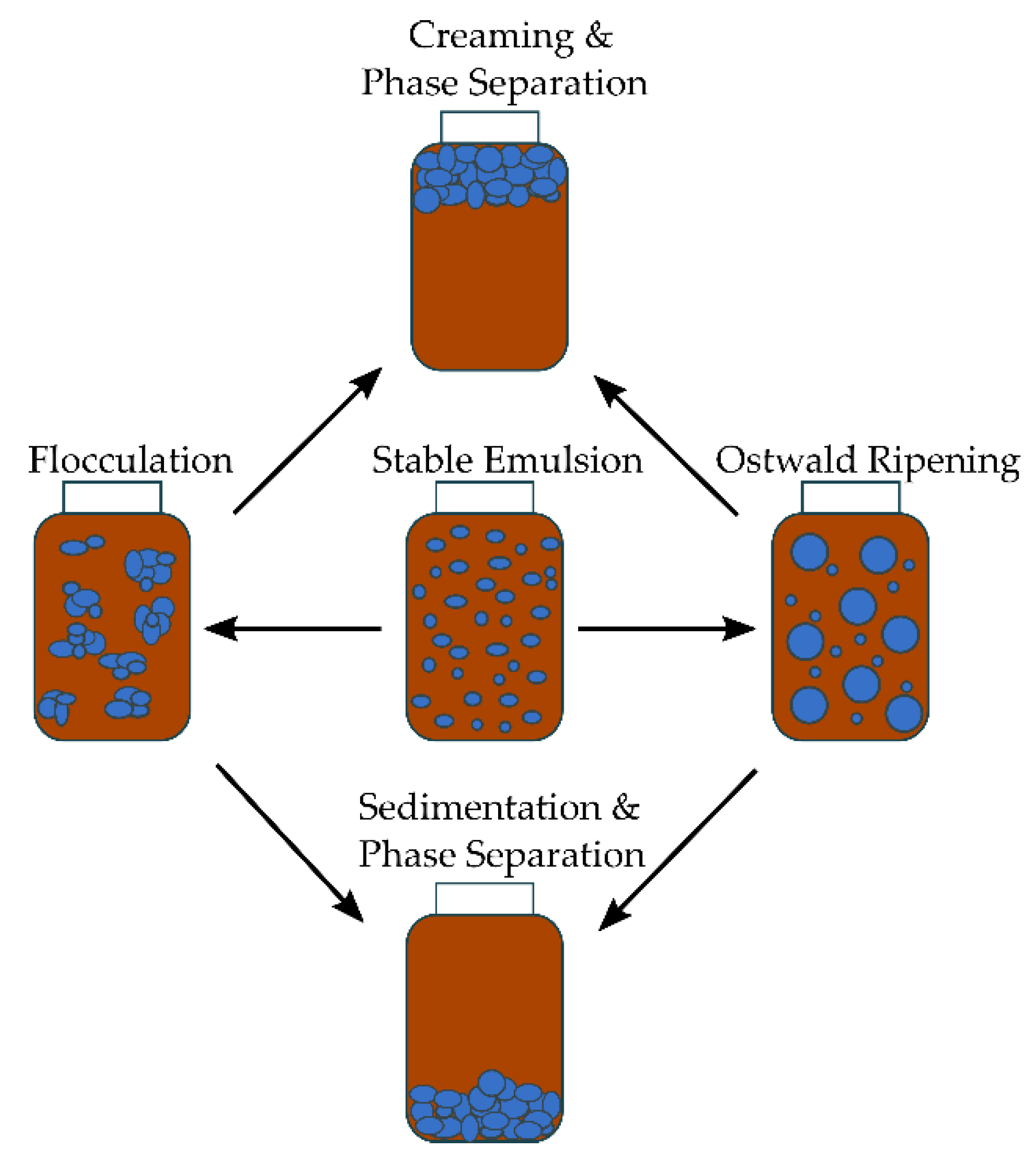
16] The process of coalescence leads to sedimentation, which may be caused by the flocculation of variously sized micelles, or Ostwald ripening, whereby the larger micelles, being more energetically stable than the smaller ones, scavenge water from smaller micelles [
13,
14,
15]. The phase separation caused by the sedimentation process is the driving factor behind establishing good calibration standards in FT-IR oil analysis, since representative, homogenous samples are critical in proper enquiries.
In an emulsion, Brownian motion tends to keep the mixture stable if drop size is small enough [
15]. A high surface potential can ward off flocculation, while a small droplet size with a negligible density difference between the dispersed (water) and continuous phases (oil) can prevent creaming or sedimentation, with creaming having a negative density difference in Stokes’ law:
where
V is the sedimentation or creaming velocity (m/s),
is the density of the dispersed phase (kg/m
3),
is the density of the continuous phase (kg/m
3),
is the acceleration due to gravity (m/s
2),
d is the particle diameter (m), and
is the dynamic viscosity of the continuous phase (kg/m·s) [
16,
17,
18]. Equation (1) (Stokes’ law) indicates that micelle diameter plays a major role in the rate of sedimentation of water in oil, leading to poor calibration standards if mixing does not break up the water droplets into sufficiently stable sizes.
For flocculation to be the driving factor in emulsion instability in a typical laboratory sample, where the rate of flocculation is relative to Brownian motion and gravitational sedimentation, an estimate of the ratio of the two types of flocculation rates can be made as follows:
where
is the ratio of sedimentary flocculation to the Brownian flocculation,
di is a micelle of one diameter (m),
k is Boltzmann’s constant (m
2kg/s
2K),
T is the absolute temperature in Kelvin,
is the ratio of two sizes of micelles
, and other parameters are defined as in Equation (1) [
17,
18]
Finding the maximum ratio of sedimentary to Brownian flocculation is a matter of differentiating Equation (2) with respect to
and solving for this size ratio; thus,
indicates that the maximum rate of sedimentation to Brownian flocculation would occur when micelle diameters are in a ratio of roughly 3 to 5 [
17]. Therefore, non-uniformity in particle size also plays a factor in phase separations.
Ostwald ripening can also lead to emulsion instability, and has been shown to be reasonably well approximated through the LSW (Lifshitz-Slyozov-Wagner) theory for emulsions with the equation:
where
is the Ostwald ripening rate (m
3/s),
r is the average micelle radius at a given time (s),
D is Einstein’s translational diffusion coefficient of the dispersed phase from the Stokes-Einstein equation (m
2/s),
is the solubility of the dispersed phase at the continuous phase interface (mol/m
3),
is the molar volume of the dispersed phase micelles (m
3/mol),
is the interfacial tension between the continuous phase and the dispersed phase (J/m
2), and
R is the ideal gas constant (J/mol·K) [
13,
15,
19]. From Equation (3) a linear relationship of the cube of micelle radial size to that of time is implied, and consequently, a stable emulsion should have a small micelle size [
15].
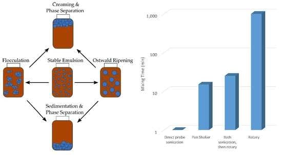
Figure 1 represents a graphical overview of emulsion instability, as previously discussed.
Based on scrutiny of the possible routes of instability, it is implied that a higher rate of energy dispersion throughout the water/oil mixture should induce better emulsification results, generating more reliable, readily repeatable results for FT-IR calibration samples with less overall variability. This study aims to understand experimentally how the energy dispersion rate throughout the water/oil mixture affects the emulsion quality, using the different mixing procedures that may be commonly available with access to modern laboratory equipment to produce better calibration standards for FT-IR analysis of water in engine oil. The techniques utilized in this study to form emulsions are the rotary (ROT) method, bath sonication only (BSO), bath sonication followed by a rotary (BSR), pan-shaker (PSH) method, and direct probe sonication (DPS).
2. Material and Methods
2.1. Sample Preparation
A container (946 mL) of a common diesel engine oil (Shell Rotella T, SAE 15W-40) was purchased from a domestic retail market in Carbondale, IL, USA. A pipette was used to make different sample concentrations by volume from fresh oil and non-deionized, distilled water. The treatments included different water proportions that contaminated the fresh engine oil (0%, 0.1%, 0.2%, 0.5%, 1%, 2%, 5%, and 10%
v/
v). A detailed description of the sample preparation used for this study can be found in a previous publication [
7]. In that study, the limit of detection (LOD) was determined, and the aim in this study was to do a similar determination with similar concentrations. For comparisons of different mixing methods, the concentrations of 0%, 0.5%, and 1% were used, since concentrations higher than these tend not to be linear in IR spectroscopy measurements [
6].
2.2. Emulsification Procedure
To ensure a sample’s homogeneity for sampling and concentration determination, each sample, including the control sample, was treated with the same emulsification procedure for each mixing method. Each sample was stored in a closed vial and left standing upright in a closed box to prevent photo-degradation. The vial would temporarily be removed for sampling, agitation, FT-IR analysis, or a photo to track any change in color.
Direct probe sonication of the sample was performed with an ultrasonic processor (Sonic Vibra-CellTM, model: VCX750, Sonics & Materials Inc., Newtown, CT, USA) with a probe (model: CV33, Sonics & Materials, Newtown, CT, USA) diameter of 13 mm at a frequency of 20 kHz ± 50 Hz and power output of 750 W with an amplitude of approximately 76 microns, by inserting the probe into the vial to within a few millimeters from the bottom. To prevent excessive heating of the sample during sonication, the vial was placed inside a water bath and the probe was cycled on for 5 s, off for 30 s. The procedure was repeated for a total of 12 times for a one minute of total sonication time. The initial and final temperatures of the samples were approximately 22 °C and 40 °C, respectively. The sonication horn was cleaned with acetone and wiped with extra low-lint Kimtech disposable wipes after each sample’s agitation. Separate samples that were exposed to direct sonication by this same apparatus, along with control samples, were sent to a commercial lab for testing of total base number (TBN) and viscosity, to determine if there was any oxidation of the oil due to incidental heating that occurred during sonication. No changes were noted. Since each vial sat in a water bath and had to be opened to allow the insertion of the sonication horn, the opening was shielded from the water bath by a cellophane tape and paraffin film covering, to prevent possible routes of contamination.
The bath sonicator had a power output of 100 W and a frequency of 42 kHz ± 2.5 kHz. The power output of the indirect ultrasonic water bath was less than that of the direct ultrasonic probe. Instead of comparing the power intensity (W/cm
2) of the two sonicators to estimate the required time for bath sonication, it was concluded that comparing the sample temperature would be more appropriate. Ultimately, it was determined that it took 56 min of sonication for the samples in the ultrasonic water bath to undergo the same temperature change as the direct probe samples had, which was from 22 °C to 44 °C. The difference was due to the following reasons: first the direct probe method involves direct contact with the sample and indirectly with the water bath, whereas the bath sonicator is in direct contact with a larger water bath with greater heat capacitance, and in indirect contact with the sample. Second, the bath sonicator has a more extensive surface area/air interface with which to dissipate heat to the atmosphere. The extended sonication time (56 min with an equivalent temperature change) was chosen to ensure a relatively similar energy absorption by the sample, since bath sonicators can have cavitational intensities unevenly spread throughout the bath [
20]. The power per unit volume was considerably lower with the bath sonicator, but the hypothesis was that the energy change within the oil column should have been nearly the same. The vials, sealed with their screw-on caps and paraffin film, were placed in a beaker of water such that, when submerged, the water level in the beaker rose to just slightly over the height of the fluid in the vials, yet remained under the bottom of the screw-on caps. This was to ensure that the entire sample within each vial was exposed to the energy of the sonicator, but also helped to eliminate another possible path of contamination.
Due to the nature of the bath sonicator driving oscillatory waves within horizontal planes without vertical mixing or turbulence, as noted by neutrally buoyant particles present in the water bath, it was hypothesized that an additional mixing method would be required to create a stable, homogeneous emulsion. A preliminary study was done to establish this necessity. Within this preliminary study only one sample was used, with two separate replications of each of the four FT-IR measurements, and these results were compared to the first of the three samples that were ultimately tested using a bath sonication followed by rotary (BSR) mixing method. Preliminary testing with periodic samplings for FT-IR analysis indicated that 25 min of additional rotary mixing was sufficient to produce an emulsion, with an O–H stretching peak that emulated a plateauing of the measurable concentration similar to that noted in a similar study using a rotary mixer [
7]. Therefore, this study includes a bath sonication method that is followed by 25 min of rotary mixing.
For the rotary mixing method, a continuous rotation was desired to reach full saturation, as noted by a plateauing of the O–H stretching peak with FT-IR measurements. This was achieved by way of a Mini Tube Rotator from Fisher Scientific at the maximum setting, 40 rpm. In a preliminary study, it was established that 60 h was the optimal time to develop full saturation. A similar method was employed for the pan-shaker method, setting the 15-min mark required to reach full saturation. The pan-shaker used was a double-arm apparatus (Red Devil Equipment Company, model: Cat 30, Plymouth, MN, USA) that would accommodate containers with a minimum height of approximately 90 mm. To use a smaller vial size (27 mm in diameter and 50 mm in height with a total liquid volume of 18 mL), a wooden spacer with a carved recess specifically made for the vial was used in conjunction with a metal band that screwed down over the middle of the vial. Equally weighted vials and spacers were used in each arm. The motion was that of a 30° rotation about a central axis at 600 rpm, with a simultaneous lateral movement from side to side of approximately 5 cm. This double action ensured a turbulent mixing.
2.3. FT-IR Spectral Analysis
The infrared spectra were recorded with a wavenumber range of 400 to 4000 cm−1 by an FT-IR spectrometer (Thermo-Nicolet Nexus 670, Thermo Electron Corporation, Madison, WI, USA). The system was purged with dry air before each measurement (background or sample) to minimize interference from atmospheric moisture. A background measurement was taken before measuring each sample. A 3 μL portion of the respective sample was pipetted from the vertical and horizontal center of the vial onto a KBr window (1 inch diameter), and a similar window was placed atop the first and rotated 90 degrees to ensure the oil was spread evenly over the windows’ faces. The KBr/oil sample was placed in a sample tray with a polytetrafluoroethylene (PTFE) ring, sized to ensure the windows were in the same physical orientation and location in the sample holder each time the experiment was performed, in order to reduce the possibility of differences in the refraction of light between each measurement. By gathering the spectra from the same location of the KBr window during the measurement of the background or sample, spatial dependent spectra were minimized. After each sample was prepared in a KBr window, four consecutive spectrum measurements were recorded. The KBr windows were cleaned with methylene chloride after each sample was tested again. The procedure above was repeated for three different sample preparations of the same concentration.
2.4. Data Preprocessing and Analysis
Before statistical analysis of the mid-peak wavenumber range of the O–H stretching band (from 3150 to 3500 cm
−1), the baselines of each whole spectrum were adjusted to minimize effects of baseline shifting between FT-IR measurements. The end of the spectral range [
6] (3970 to 3995 cm
−1), where each spectrum flattens due to the lack of any detectable signals, was shifted to zero on the absorbance scale, and the same shift was applied to the entire baseline of each respective spectrum [
6].
To determine the concentration of water that could be measured by FT-IR, the peak amplitude of the entire broad peak water signal around the 3400 cm
−1 wavenumbers was used for relative comparison, using a two-point baseline [
21]. The areas of water absorbance were found by two-point Gaussian curve fitting after eliminating the continuum background, and also by integration from between the wavenumbers 3150 to 3500 cm
−1. Unless otherwise stated, the integrated values were used in comparisons.
Water absorbance areas versus water concentration were used to quantify the limit of detection (LOD) and limit of quantification (LOQ) [
22] for water concentrations in oil by FT-IR spectral analysis. LOD and LOQ were calculated from a linear regression fit, where
and
. Here,
Sa is the standard deviation of the response estimated from
y-intercepts of each respective regression line, and
b is the slope.
Significant differences among the data were analyzed using ANOVA (alpha = 0.05) modeling. When the results were highly significant, p < 0.01 was reported rather than the actual p-value. It was used to disclose any significant differences among the different mixing methods. This method was utilized in the areas of the O–H stretch from 3150–3500 cm−1.
3. Results and Discussion
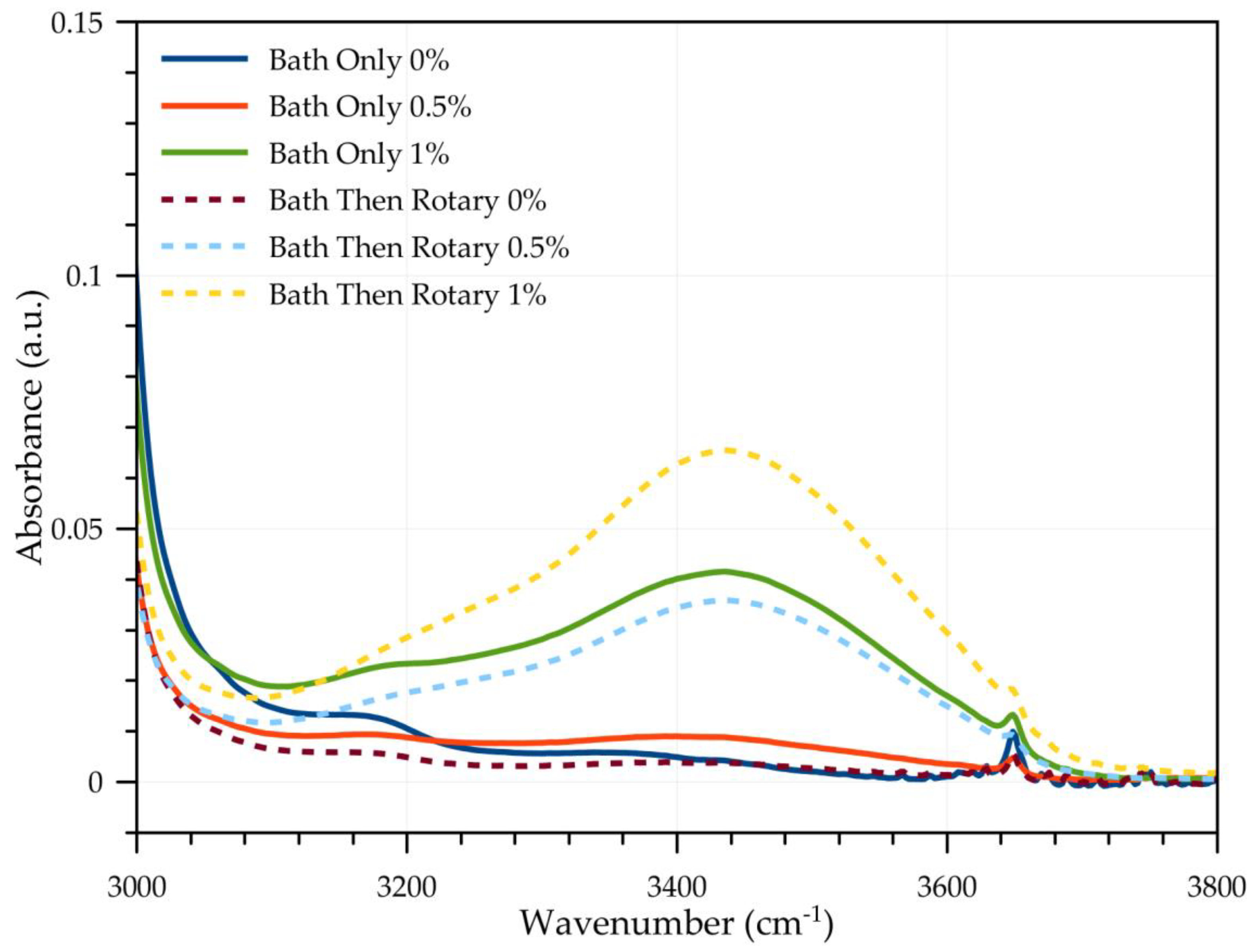
FT-IR results of bath sonication only (BSO) and bath sonication followed by a rotary (BSR) mixing were compared with 0%, 0.5%, and 1% water contaminated engine oil, as shown in
Figure 2 and
Figure 3. While there were no significant differences (
p = 0.18) between BSO and BSR at 0%, the BSR method had significantly higher values for area in the 3150–3500 cm
−1 region than BSO at both 0.5% (
p < 0.01) and 1.0% (
p < 0.01) rates. At 0.5%, the mean area was 8.1 for BSR, compared to only 2.9 for BSO. At 1.0%, the mean area was 15.2 for BSR compared to 11 for BSO. When comparing means of contamination rates for each mixing method, BSO resulted in significant differences (
p < 0.01) among the rates but was only able to distinguish the mean of 1.0% from the lower rates, with no difference between 0% and 0.5% rates. BSR also resulted in highly significant differences (
p < 0.01) among the contamination rates, with significant differences among each of the rates.
The nature of the wave energy being relatively coplanar with the surface of the water bath of the bath sonicator did not drive water within the mixing vial into the less dense oil, even though it did break the water particles apart into particles small enough to allow for emulsification. This is evident in
Figure 2 and
Figure 3 of the FT-IR measurements. The horizontal agitation of the mixture when using a bath sonicator necessitated the use of rotary mixing as well to achieve a full emulsion. Thus, the BSO method was rejected as a suitable method for generating FT-IR calibration standards of water in oil emulsions.
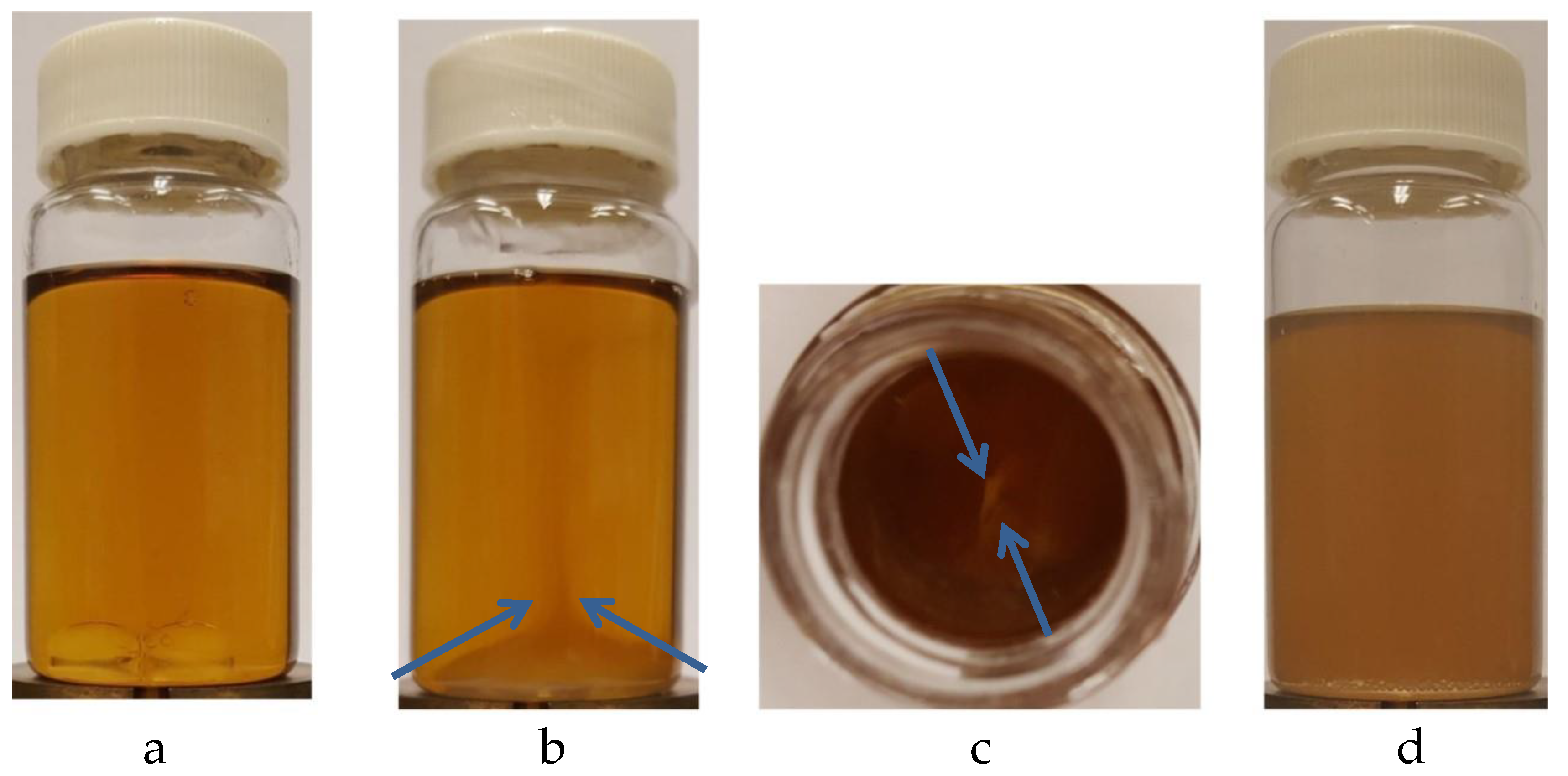
An interesting phenomenon was also observed with bath sonication only. After sonication, the micelles and the small individually dispersed water droplets appeared to maintain stored energy that could be released with a slight jarring motion by setting down the vials, upon which many of the micelles would rise geyser-like into the oil column, approaching the upper surface of the oil. Further mixing was required to disperse the remaining droplets more homogeneously.
Figure 4a–d demonstrates this exciting phenomenon in fluid dynamics.
In general, the standard deviation appears to be much higher for the BSR method than for the BSO method, especially at the 0.5% concentration. This is, in part, attributed to the fact that the overwhelming bulk of the water primarily remained on the bottom of the container, and was simply not being sampled with each subsequent replication at the 0.5% concentration. In addition, only a small portion of the 0.5% or 1.0% water concentration erupted up into the rest of the oil column; these were likely the smallest micelles that were formed during the sonication procedure, and would subsequently dissipate into the continuous phase rather homogenously and be small enough to reduce the variability of the reading due to scattered infrared light. However, when this mass of individual water droplets that remained at the bottom of the vial was mixed throughout the oil to get a more truly representative sample, variably sized micelles were most likely present, and not just the smallest ones that had erupted up into the oil.
When comparing all mixing methods, it was noticed that all are relatively similar to one another, with much overlap of the standard deviations of individual samples and testing procedures. The highest variability appeared in the bath sonication followed by rotary mixing (BSR). This is likely due to the cavitation being non-uniformly spread throughout the water bath; a slight variance in location of subsequent samples could lead to poor repeatability in results [
23], which is demonstrated in
Figure 5.
It is also worth observing that the highest standard deviations in the O–H stretching band of FT-IR results for individual samples occurred in the BSR method, with the standard deviation (STD) being 23% of the mean measurement; ROT with the STD being 19% of the mean; PSH with the STD being 18% of the mean; and lastly by DPS, with STD being 11% of the mean.
The ANOVA results looking for significant differences between the different concentration rates according to mixing method are summarized in
Table 1. Within each mixing method, means of the 0%, 0.5%, and 1% contamination rates were significantly different from each other. The rotary mixing (ROT) method of 1440 min, the bath sonication method of 56 min followed by rotary mixing of 25 min (BSR) method, the direct probe sonication mixing (DPS) method of 1 min, and the pan shaker mixing (PSH) method of 15 min all resulted in highly significant differences (
p < 0.01) among the contamination rates, with each rate significantly different from the others for their respective techniques, indicating that the mixing times used for each method were sufficient.
The four distinct mixing methods were also compared by ANOVA to determine if a significant difference existed among the methods for producing results at the given concentrations. The four mixing methods were examined at the 0.5% contamination rate, based on the area of the 3150–3500 cm−1 wavenumber range. There was a significant difference (p < 0.05) among the mixing methods. The PSH method had a significantly higher absorbance than the ROT method; otherwise, there were no significant differences among the four mixing methods. Based on these results, the ROT method would not be recommended. Selection among the PSH, DPS, and BSR methods would depend on available mixing time. BSR may be rejected based on the requirement of bath sonication and rotary mixing equipment, and the extended time required. DPS is preferred for the shortest mixing time, but if DPS equipment is not available, PSH may be preferred.
In a previous study, each sample was agitated for about two hours with a rotary device (Mini Tube Rotator, Fisher Scientific, Hampton, NH, USA) and left for about 24 h before performing the FT-IR analysis, to allow any bubbles formed during agitation to disperse [
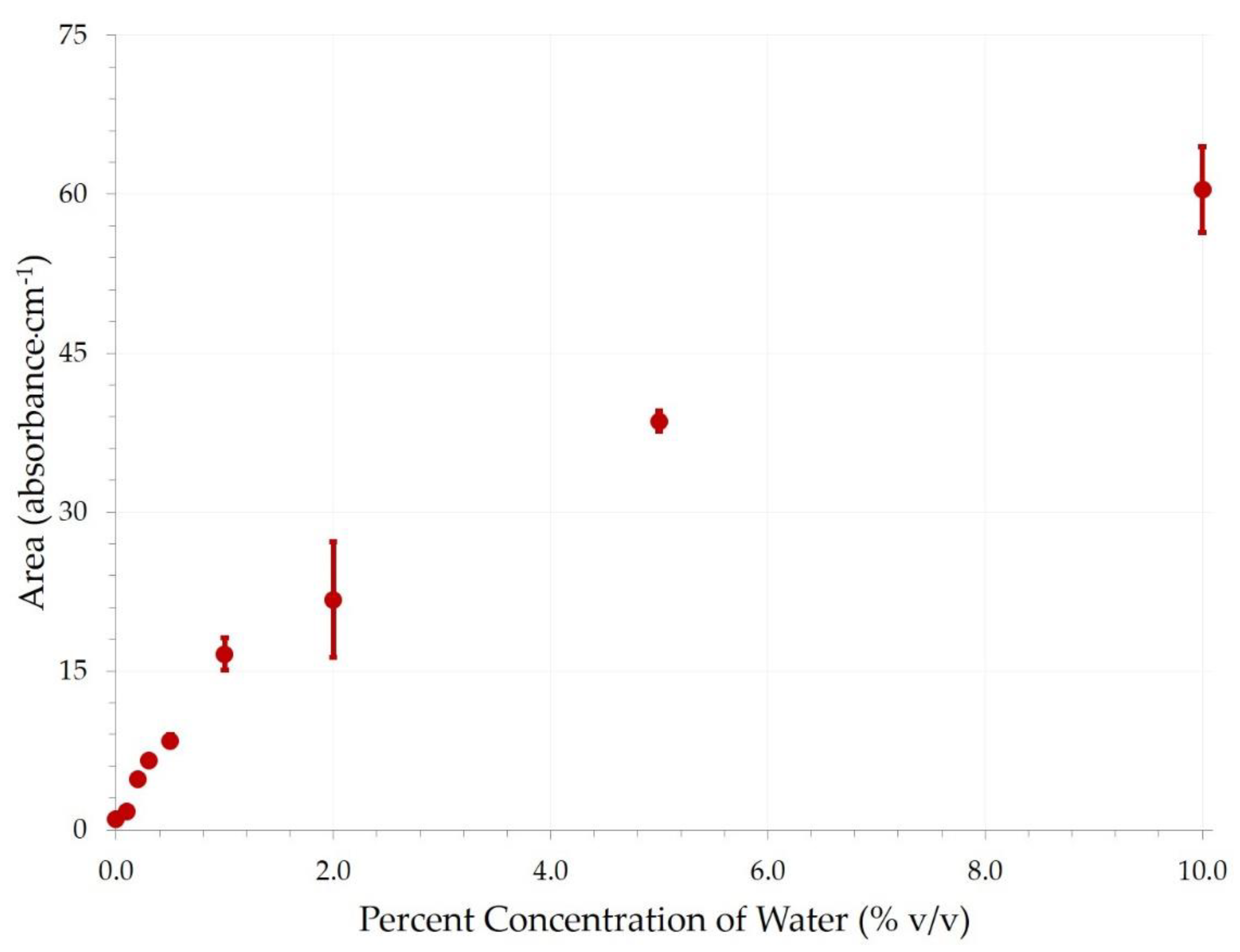
7]. This procedure was repeated weekly. This study aimed to show the importance of emulsification, and sufficient reaction time to form emulsification, in producing accurate calibration samples. At week 9 in the previous study, the oil appeared to reach full emulsification, and these results were compared with one minute of direct sonication from this study. The results of the 0% to 10% water in oil concentrations, as seen in
Figure 6, represent the areas of the O–H stretching from 3150–3500 cm
−1 after one minute of direct probe sonication. These results reasonably mimic the results previously published for rotary mixing at week 9 [
7].
In order to compare this research with a previous study [
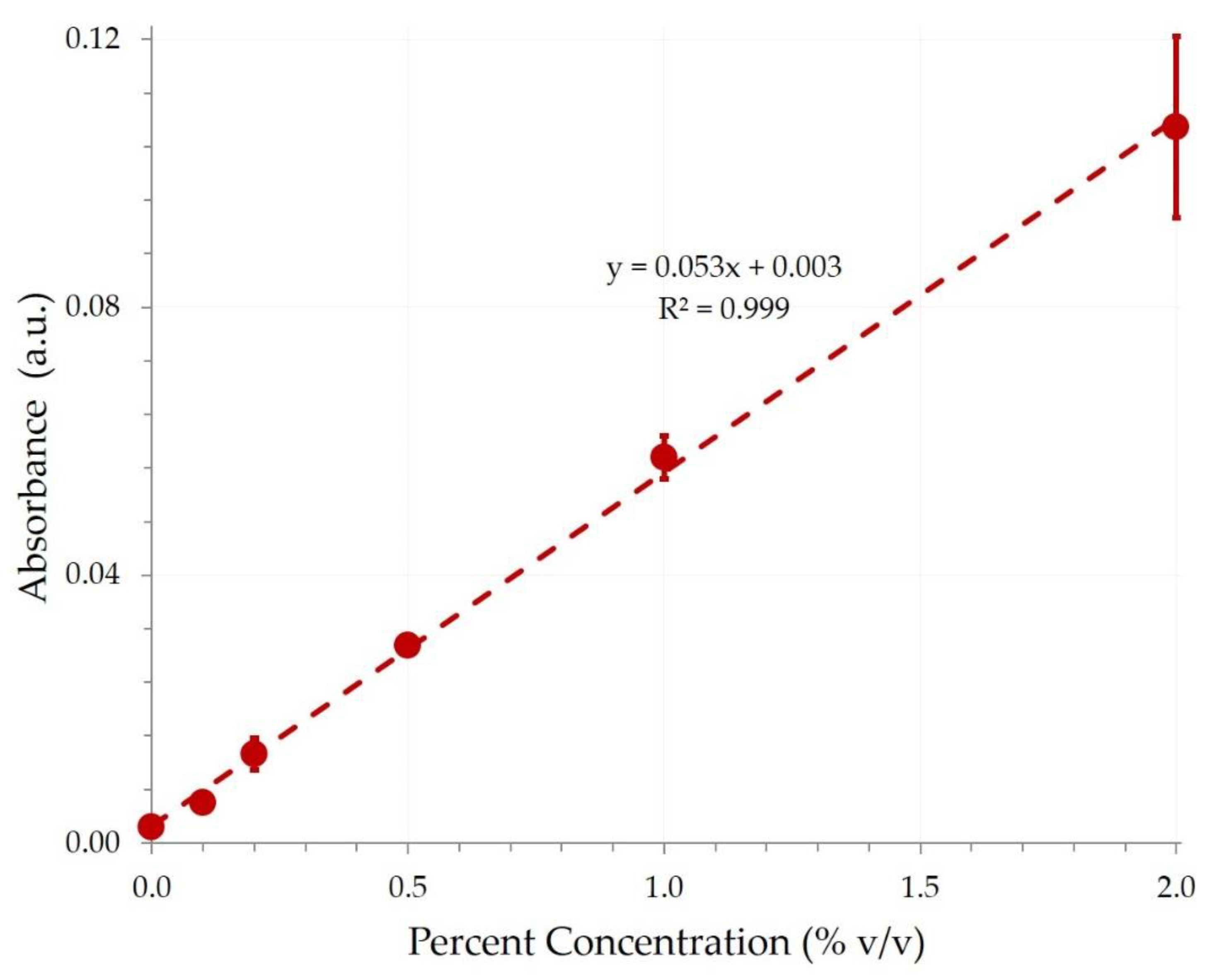
7], the peak amplitudes of the first several concentrations of water (0%, 0.1%, 0.2%, 0.5%, 1%, and 2%) were plotted, to use linear regression fitting to establish the LOD and LOQ by the quickest method employed for emulsification—direct probe sonication. The slope of the first six water concentrations, as mentioned above, were plotted from each replication, and this was used to calculate the LOD and LOQ for each replication, which were then averaged.
Figure 7 shows the mean values of these peak amplitudes for the different replications, with standard deviation error bars.
In
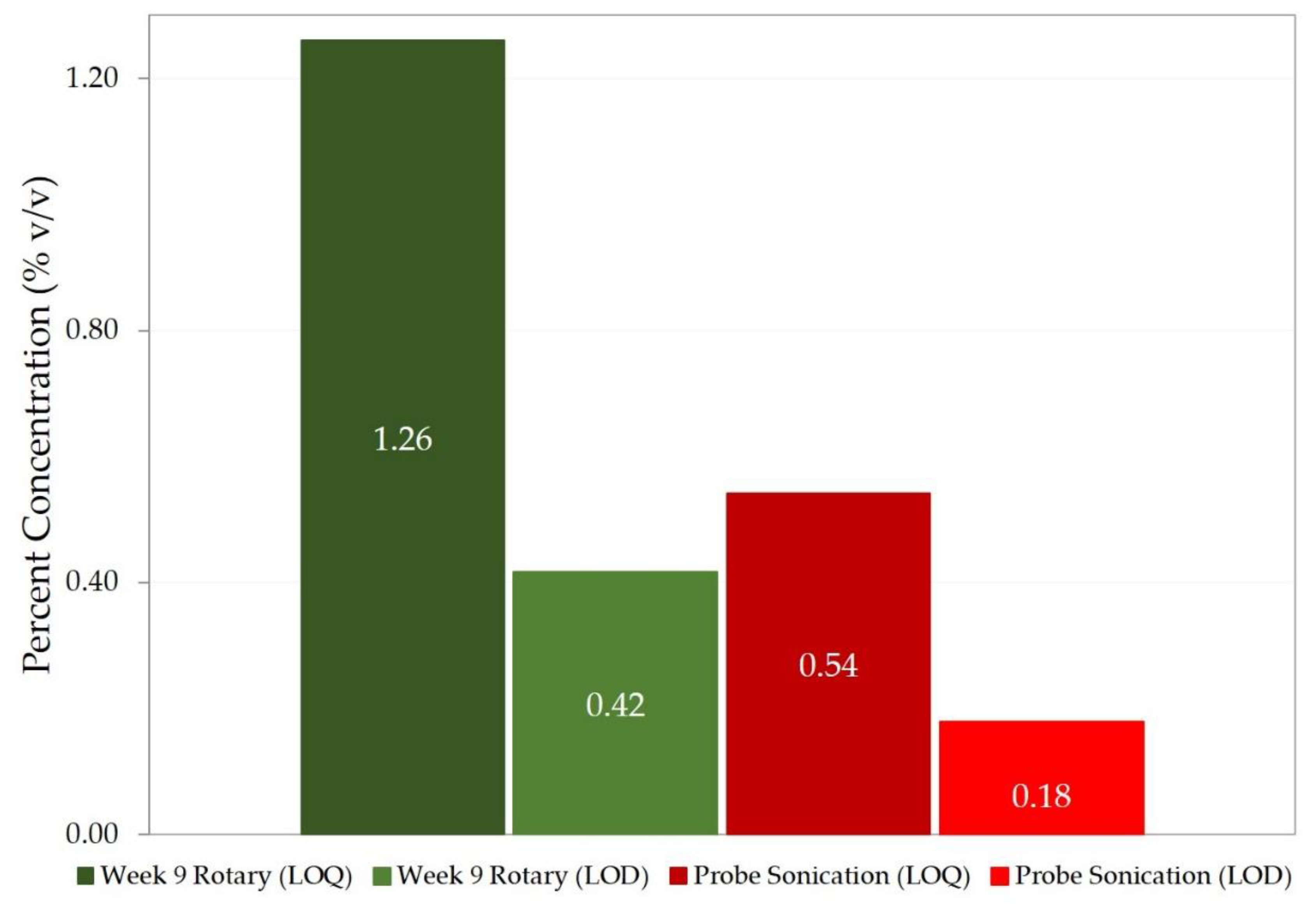
Figure 8, the results of the LOD and LOQ from a previous study of rotary mixing over time [
7] are compared to the new results of ultrasonic probe sonication of one minute total duration. The increase in ability to detect lower concentrations of water contamination is evident with direct probe sonication. It was hypothesized that an improvement in the detection limit would likely occur with the use of the ultrasonic probe, as the high-energy sonicator would produce more homogeneity by emulsifying the samples to smaller, more uniform micelle sizes. More consistent, smaller, more stable micelles should add to the reproducibility of tests and ensure more accurate sampling when pipetting.
To lend credibility to the hypothesis that using high power output mixing methods to emulsify engine oil and water would create smaller and more consistently sized micelles, it is worth noting that within the four main methods of emulsification, despite having similar FT-IR readings for the same concentrations, the rotary mixer (lowest energy output per unit time) produced the highest color change (from the golden amber of new, non-contaminated oil to the milkiness seen in the rotary mixed oil and water samples).
Figure 9a–c displays this difference in color change for the same concentrations by different methods. The micelles produced after direct probe sonication were visible but not resolvable with an optical microscope with a 100× objective, and using dynamic light scattering (DLS) or photon correlation spectroscopy also yielded inconclusive results for likely size distribution, likely due to the opacity of the samples tested. They were tested without diluting the samples and potentially altering the chemistry, as the proprietary additives in oil that partially dissolve in water could possibly change their solubility, due to a change within the intermolecular forces of an altered continuous phase. Conducting a DLS experiment at different concentrations of a nonpolar solvent, and with different solvents, could potentially rule out this effect as negligible or provide a calibration curve to analyze said effect. However, a more reasonable approach would be to use an ultraviolet microscope to more definitively establish the micelle size without disrupting the chemistry.
As micelles coalesce into larger sizes, the milky color eventually appears in all methods. This milky appearance shows up in the pan-shaker and BSR samples in less than an hour, and in the direct probe samples in several hours, suggesting a more stable and uniform distribution of nanoemulsion sized micelles. If nanoemulsions are small enough, they can be nearly transparent [
24], but the driving force behind emulsion instability with such nanoemulsions is Ostwald ripening [
25,
26]. When re-sonicated, the samples once again lose the stronger milky appearance and return to a freshly sonicated color, which indicates that this is not a chemical change due to water interacting with oil additives, but a particle size change affecting the scattering of light.
The ripening of the micelles was timed from the just after sonication to a point in time where they were resolvable with an optical microscope. With this information, in conjunction with Equation (3), one can estimate the beginning unresolvable micelle size. Einstein’s translational diffusion coefficient within Equation (3) can be broken down as follows:
where
is a constant relative to ratios of the diffusing molecules to the continuous phase,
is the initial radius of the diffusing micelles, and
is the dynamic viscosity of the continuous phase [
27].
Solving numerically for
, with
mol/m
3 for lubricating oil with additives [
28],
m
3/mol,
J/m
2 [
29], and
kg/m·s [
30], the initial micelle size, ascertained from a directly sonicated sample with 10% water contamination 24 h and 96 h later, was approximately 140 nm in both instances. The strikingly similar values lend a small bit of credence to the validity of the equation being able to predict the initial micelle size, and that Ostwald ripening may be the primary growth factor in this scenario. However, one would expect to be able to resolve micelles as small as 100–110 nm. These were observable but not resolvable. This discrepancy may be due to the fact that not all coefficient values for oil were for specifically for 15W-40 Shell Rotella T. In particular, the solubility of water in the continuous phase
was based on an estimate for lubricating oil with typical additives. Plus, the solubility estimate is likely low, since the capillary length of the micelles would be in the order of nanometers [
31].
Lastly, it may be of value to illuminate the difference in required mixing time with the rotary device. A previous study using the same rotary device required approximately 20 total hours of complete mixing at two-hour intervals over the course of 9 weeks to produce fully emulsified samples of equal concentrations to those produced under 60 h of constant rotation [
7]. This sheds light on the reaction time it takes for the emulsifiers present within the engine oil to bind with the water to form a stable emulsion. By drastically increasing the surface area of the water micelles and increasing the interaction of water binding agents already present in the engine oil through the violent turbulence caused by direct sonication, this process can be sped up by several orders of magnitude.
