Lubrication Performance of Engine Commercial Oils with Different Performance Levels: The Effect of Engine Synthetic Oil Aging on Piston Ring Tribology under Real Engine Conditions


Abstract
1. Introduction
2. Experimental Details and Methods
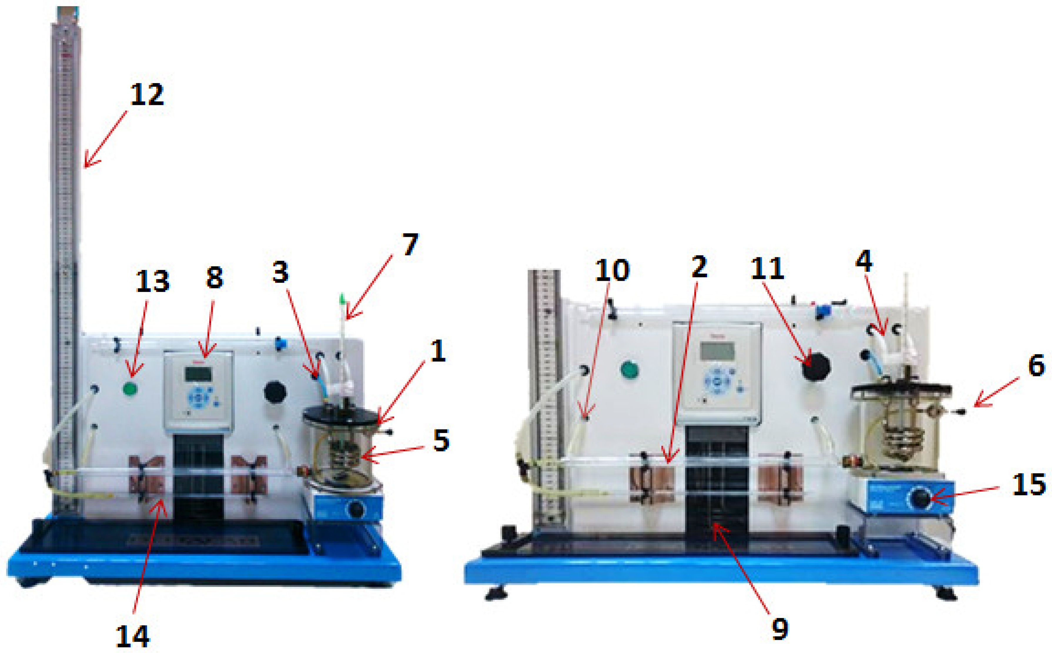
2.1. Description of the Capillary Tube Viscometer
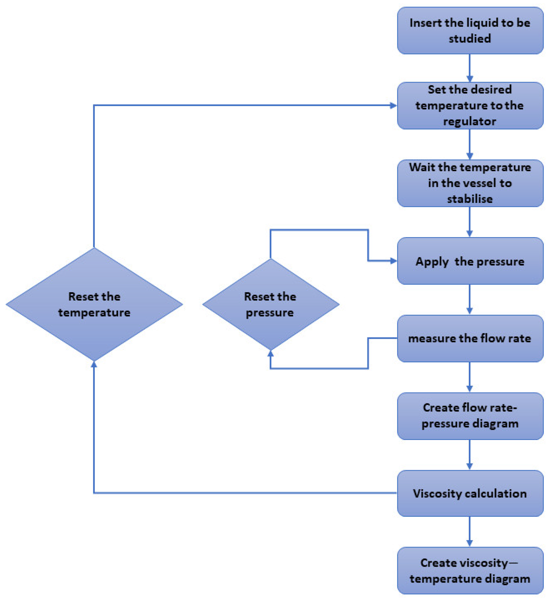
2.2. Method of Viscosity Measurement with EH105 Viscometer
2.3. Uncertainty Analysis of Viscosity Measurement
- Uncertainty in the measurement of pressure,
- Uncertainty in the measurement of flow rate,
- Uncertainty in the measurement of volume,
- Uncertainty in the measurement of time,
- Uncertainty from the radius of capillary tube,
- Uncertainty from the length of capillary tube,
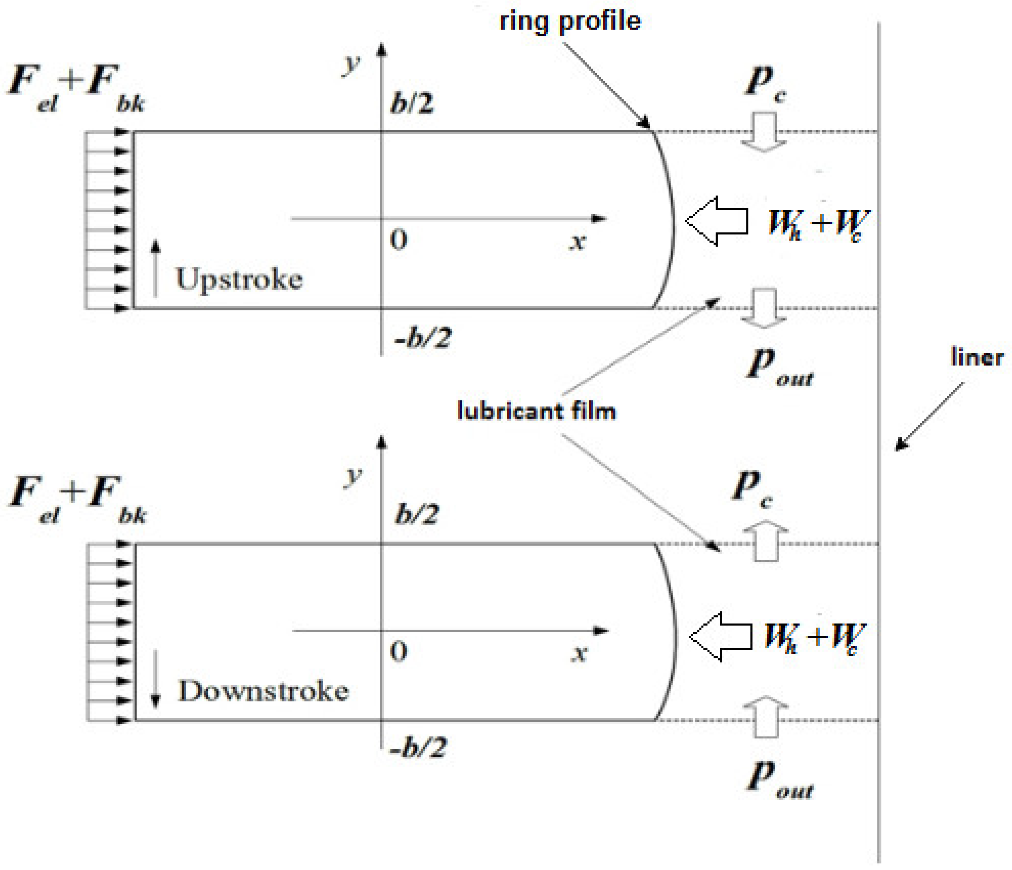
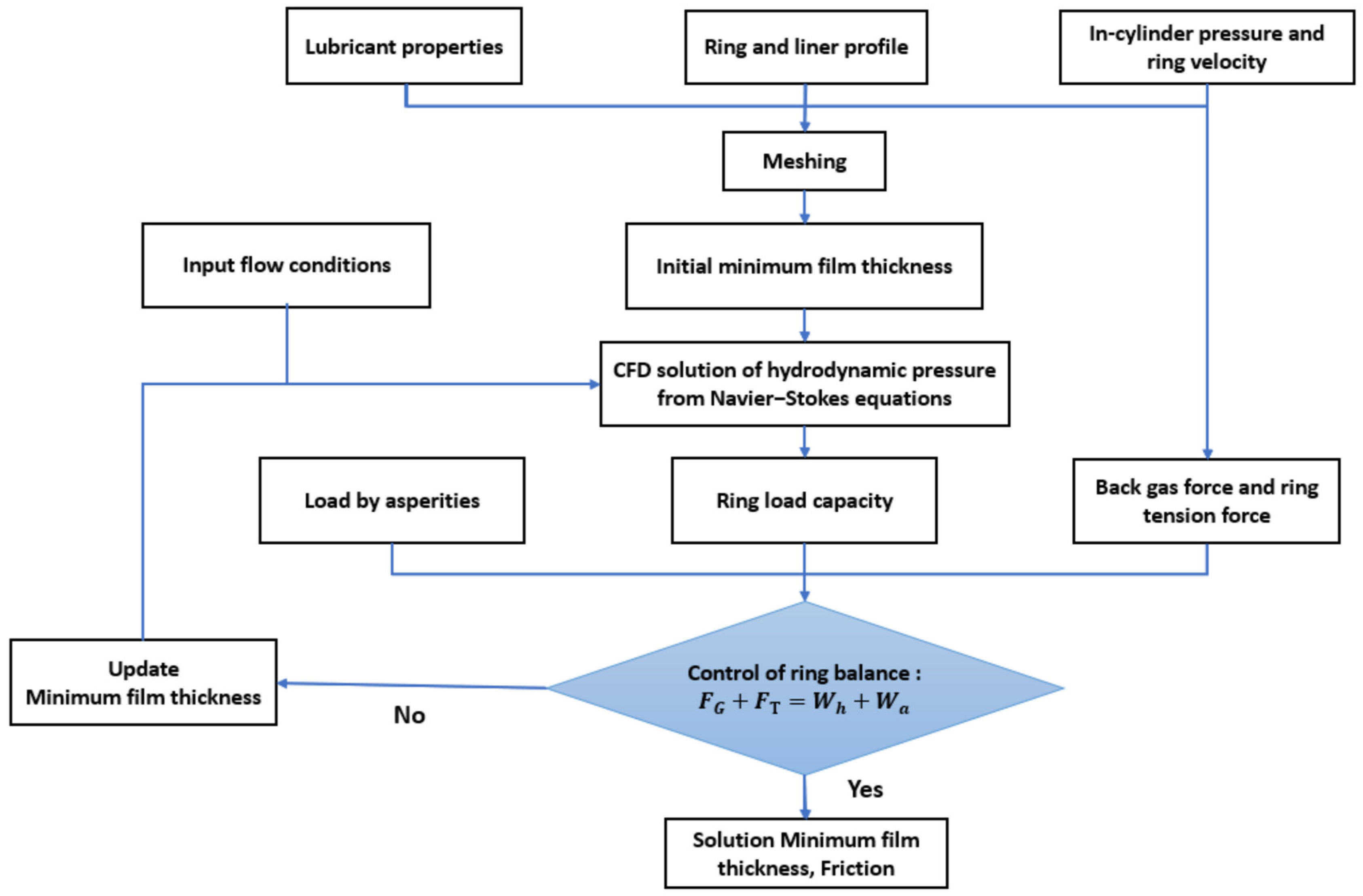
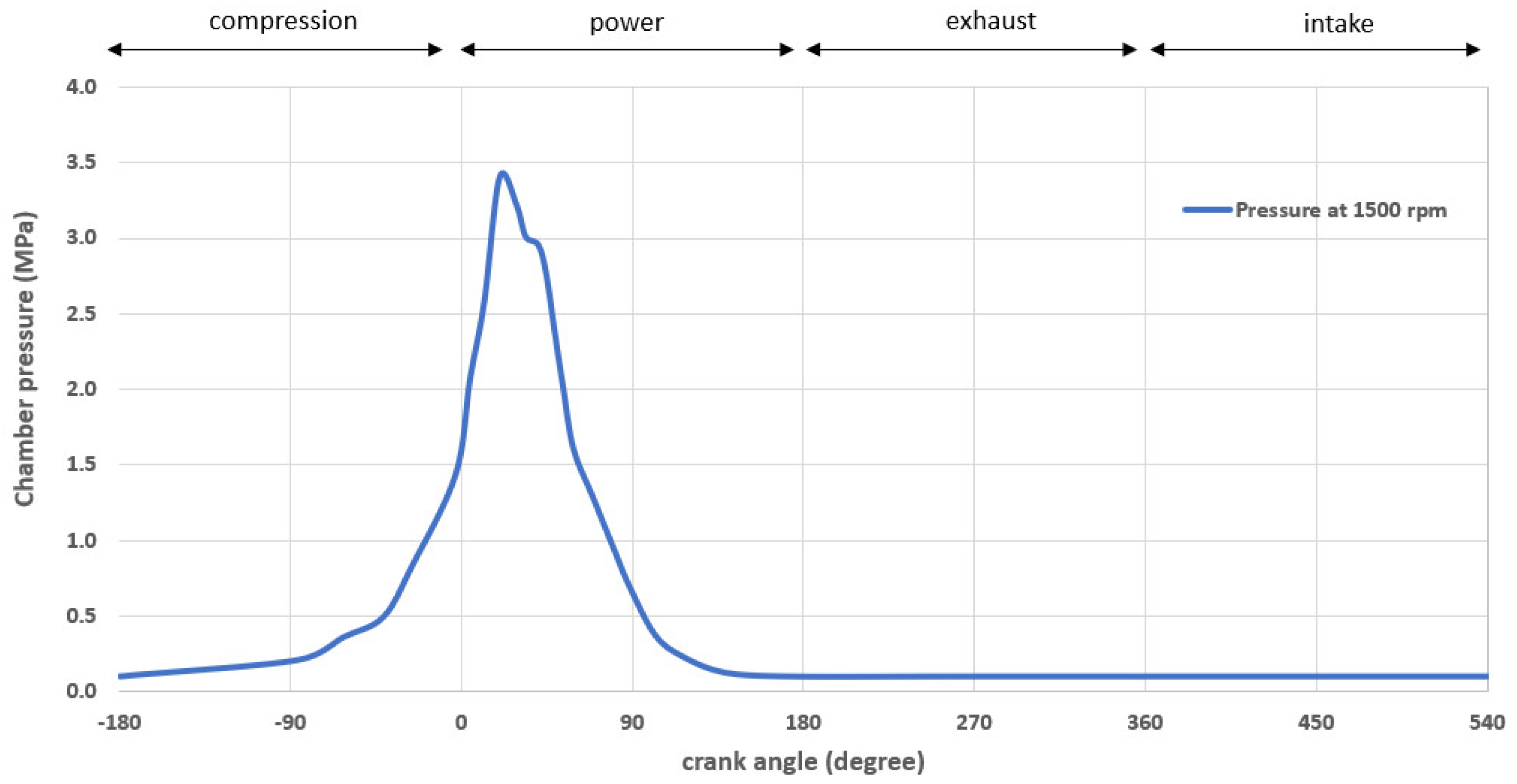
2.4. CFD Quasi-Static Analysis of Piston Ring-Liner Conjunction
3. Results and Discussion
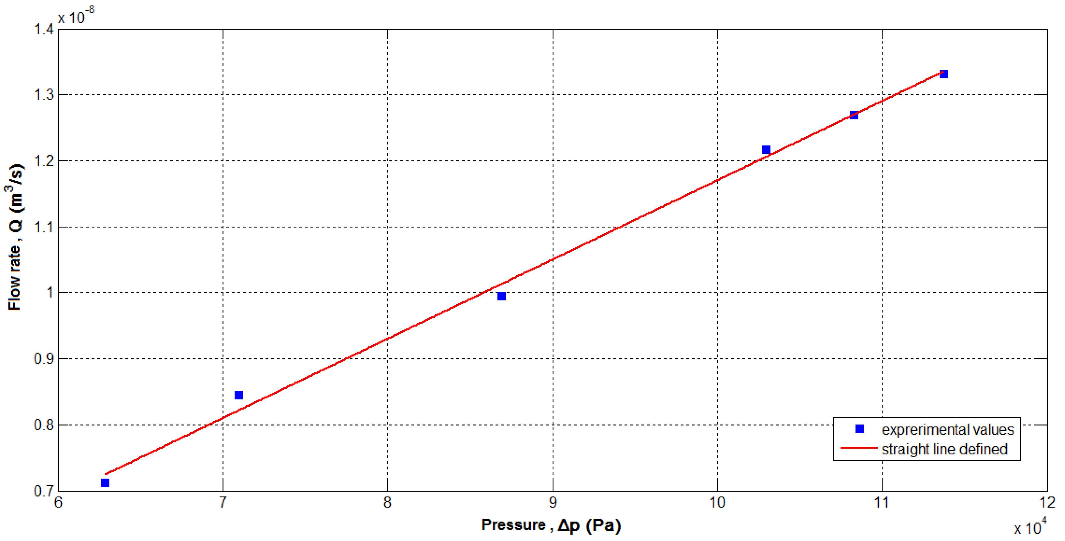
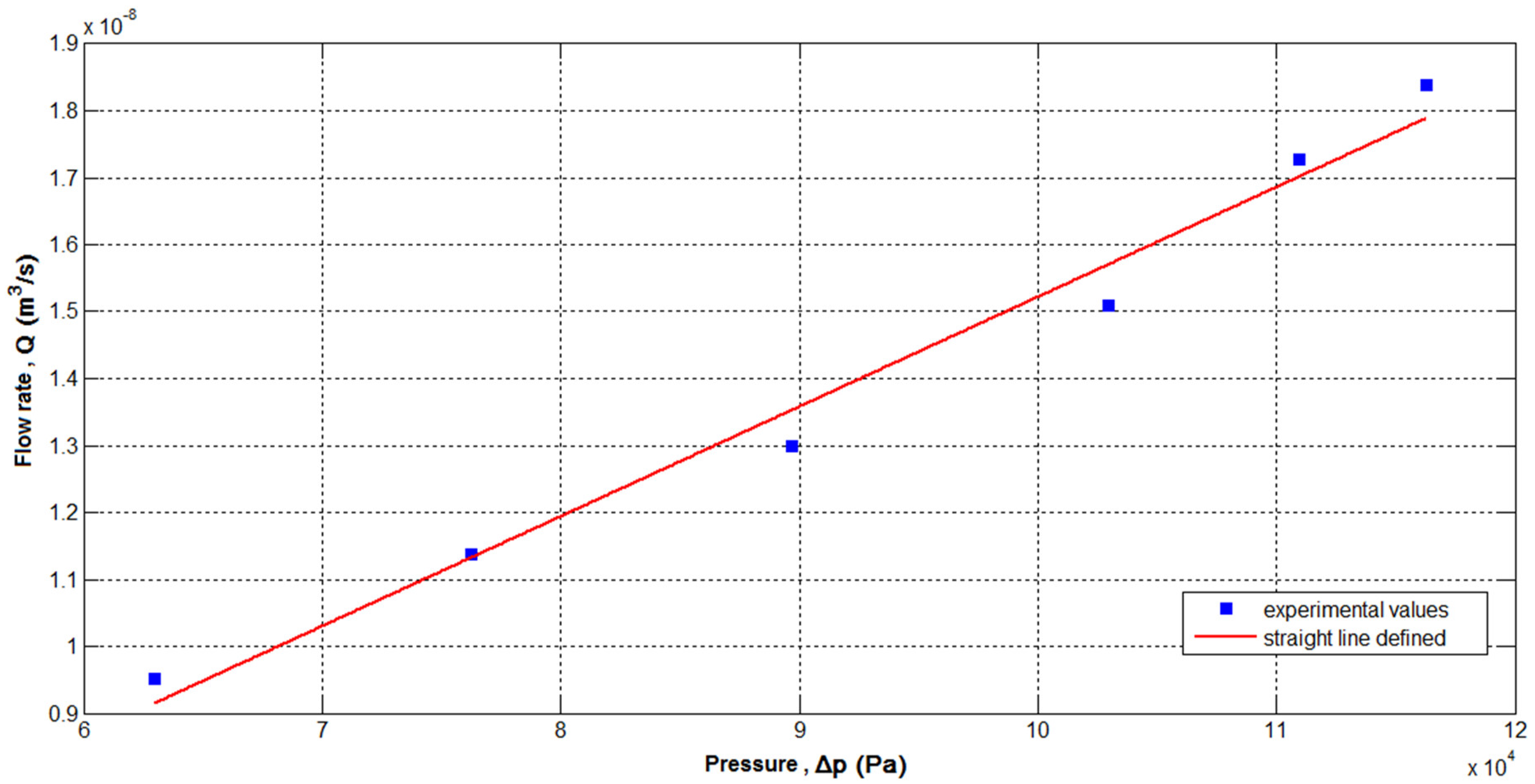
3.1. Validity of Viscosity Measurement
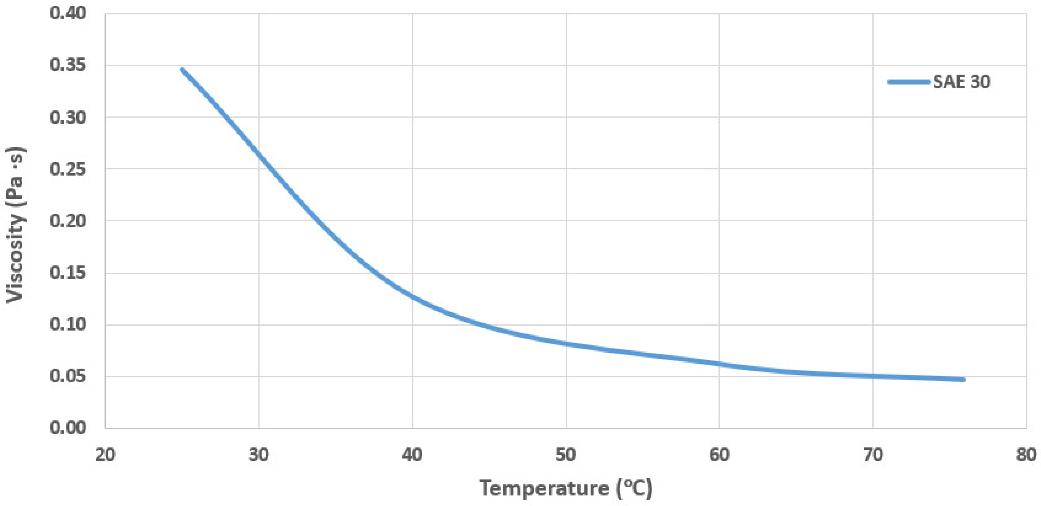
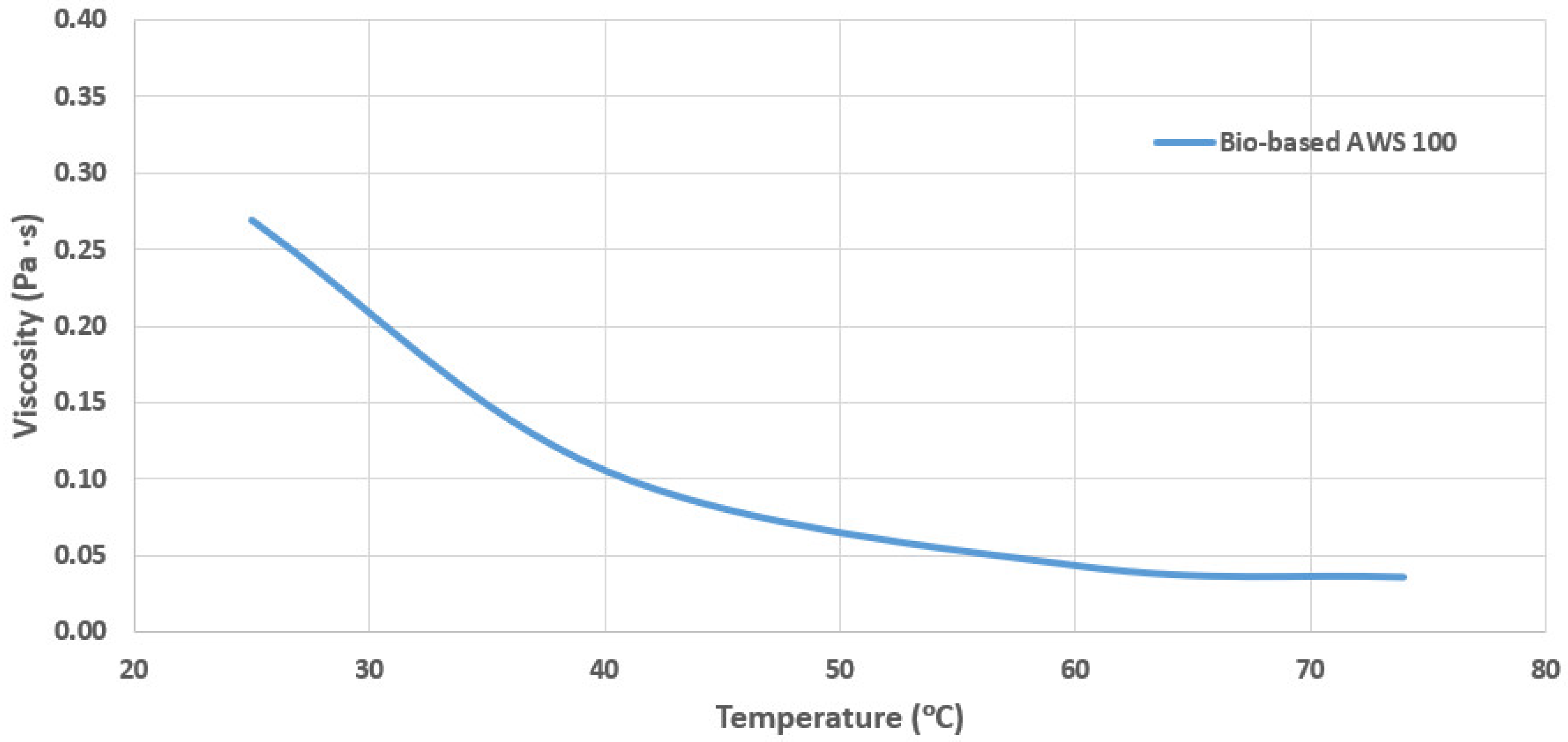
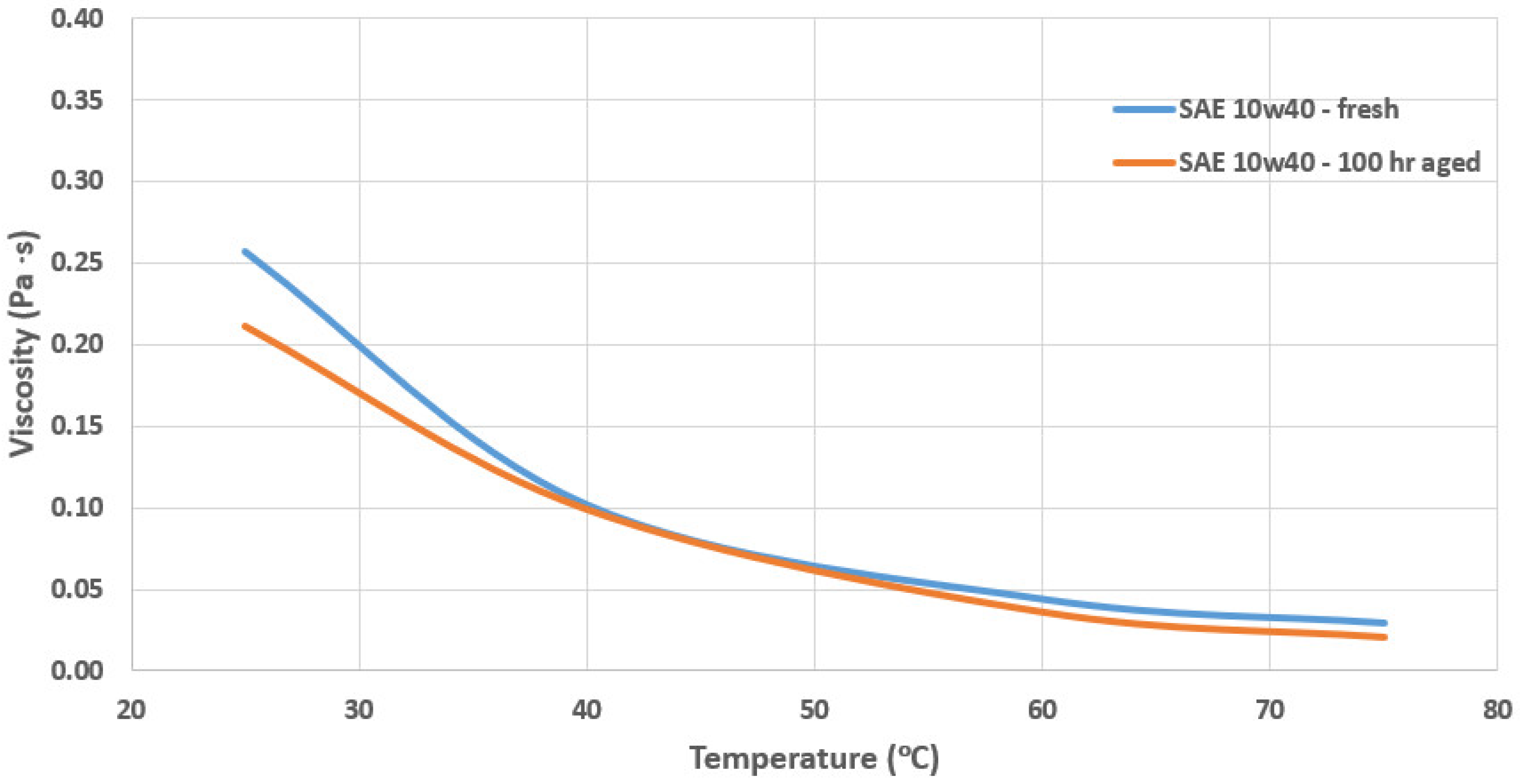
3.2. Viscosity Measurements for Commercial Engine Oils
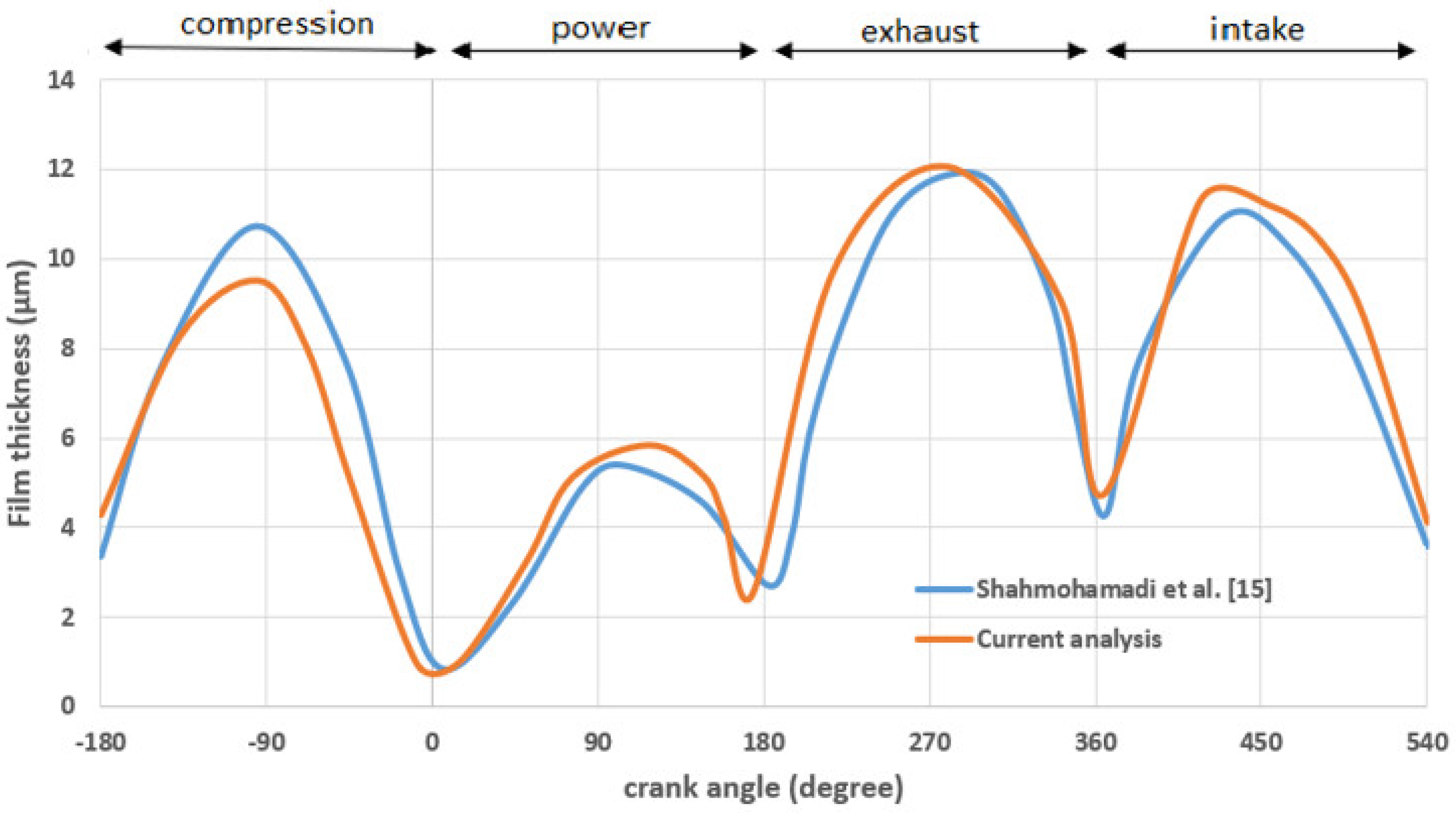
3.3. CFD Model Validation
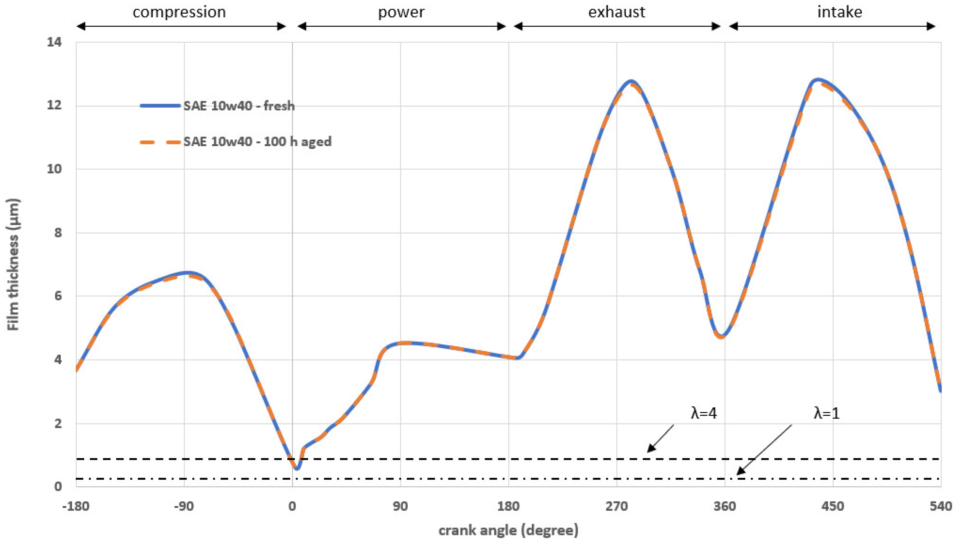
3.4. The Effect of Synthetic Oil Aging on Piston Ring Tribology
4. Conclusions
- The variation of the dynamic viscosity for the engine oil SAE10W40 is more than 19% at 25 °C and more than 28.5% at 75 °C.
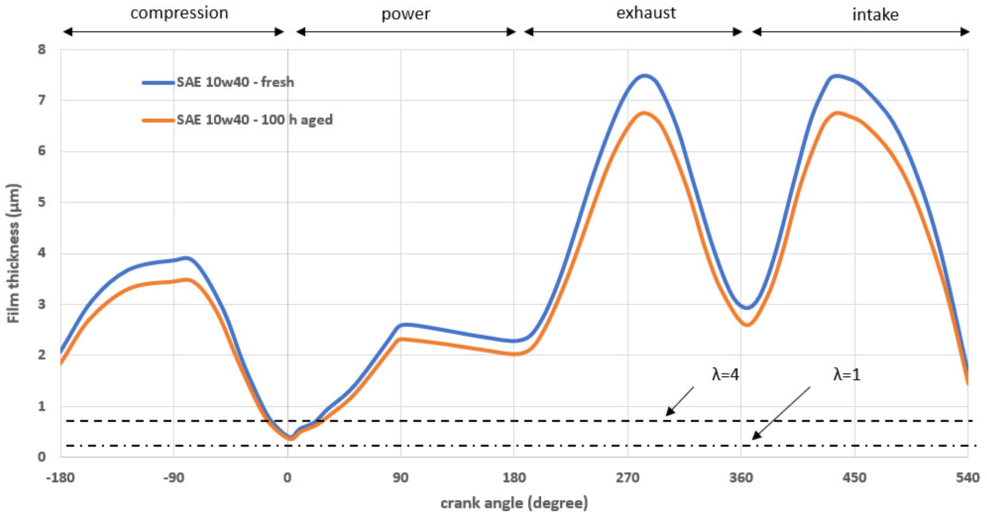
- The minimum film thickness has insignificant variation through the crankshaft angles for the fresh and aged SAE10W40 oil at 40 °C, whereas very high variation appears as temperature increases. In practical terms, there is a significant reduction in the order of 13.5%, for example in 300 degrees, due to the lubricant’s viscosity temperature variations for 2 MPa test pressure at 75 °C.
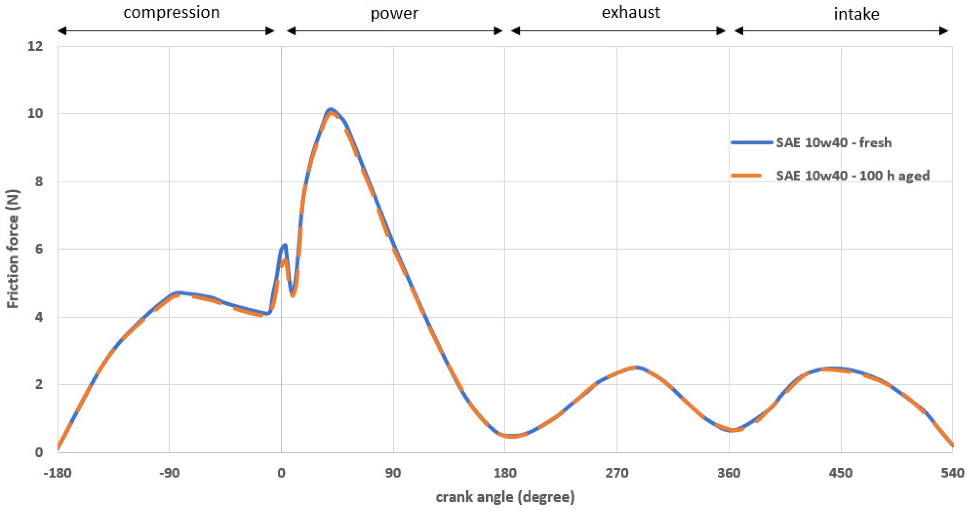
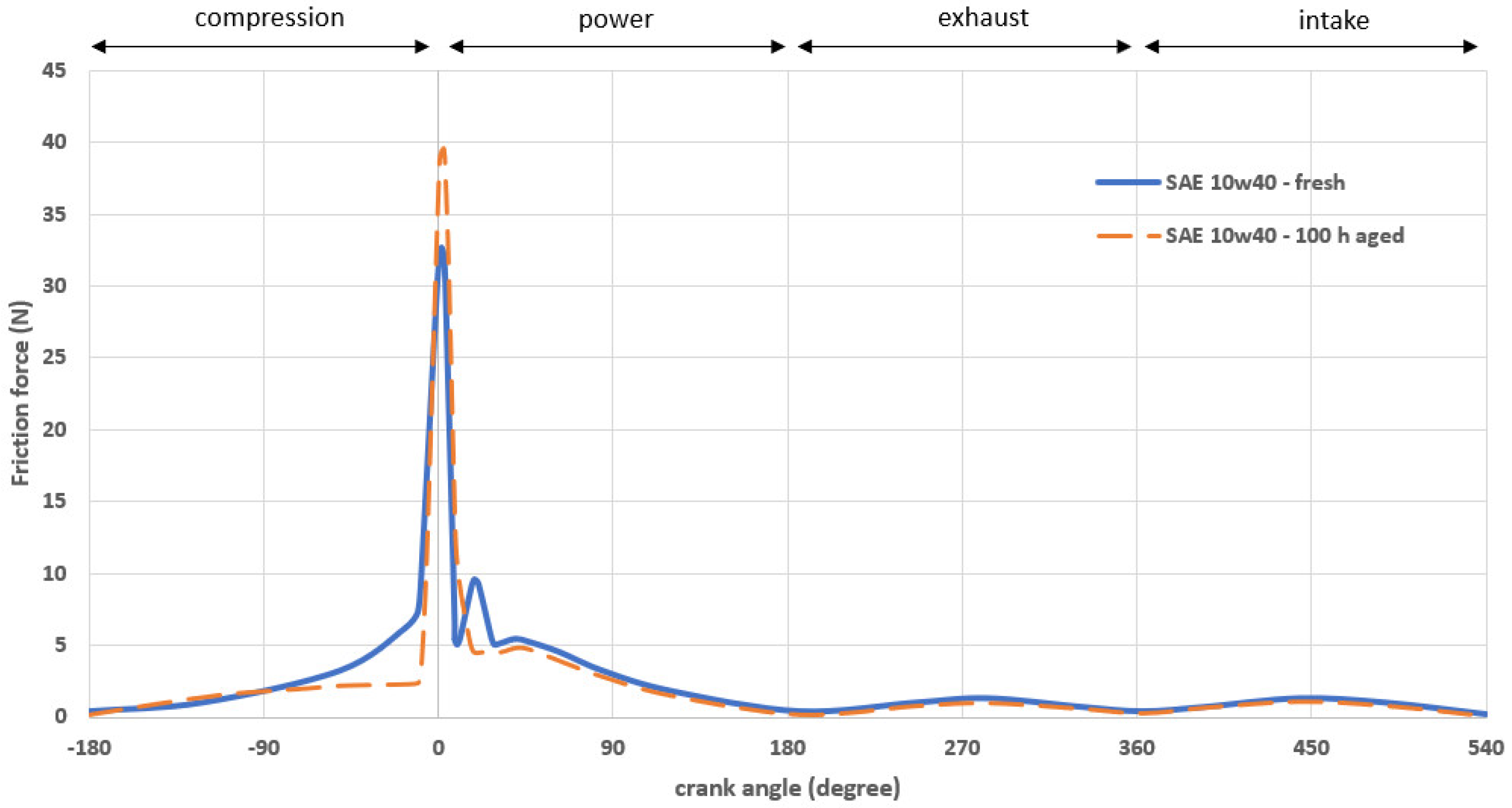
- The variation of total ring friction is almost 7.8% at the TDC between fresh and aged oil. The smaller value concerns aged oil, due its slight viscosity variation at 40 °C. Instead, boundary friction is higher, 19.25% at 75 °C, for aged oil than for fresh oil. This means that aged oil significantly influences in engine friction losses and contact wear. The impact of oil aging on ring and liner wear is the next plan of this work.
Author Contributions
Funding
Conflicts of Interest
Nomenclature
| A | nominal contact area |
| Ac | asperity contact area |
| b | ring face-width |
| dgap | ring end gap |
| E’ | equivalent (reduced) modulus of elasticity |
| Ering | Young’s modulus of elasticity of the ring |
| El | Young’s modulus of elasticity of the liner |
| F | applied ring load |
| ftot | total friction |
| ffl | viscous friction |
| fb | boundary friction |
| FG | combustion gas force |
| FT | ring tension force |
| F5/2, F2 | statistical functions |
| h | lubricant film thickness |
| hmin | minimum film thickness with time |
| hs | ring axial profile |
| Iring | second moment of ring area |
| ph | hydrodynamic pressure |
| pel | ring elastic pressure due to fitment |
| pbk | ring back gas pressure acting behind the inner ring rim |
| pc | combustion pressure |
| pout | outlet pressure at the ring conjunction |
| patm | ambient pressure |
| rcr | Crank-pin radius |
| ro | nominal bore radius |
| t | time |
| w | ring radial width |
| Wc | load share of asperities |
| Wh | load carried by the lubricant film |
| X | parameter for load balance criterion |
| Greek symbols | |
| a* | modified pressure–viscosity coefficient |
| δp | local contact deformation |
| ζ | surface density of asperity peaks |
| κ | average asperity tip radius |
| λ | Stribeck oil film parameter |
| λCR | control ratio |
| μ | lubricant dynamic viscosity |
| μο | ambient dynamic viscosity |
| ρ | lubricant density |
| ρο | lubricant density at atmospheric pressure and ambient temperature |
| σ | root mean square roughness value of examined tribo pair |
| ς | coefficient parameter of boundary shear strength |
| τ | viscous shear stress |
| το | Eyring shear stress of the lubricant film |
| υring | ring sliding velocity |
| ϕ | crank angle |
| χ | step for minimum film thickness loop |
| ω | rotational crankshaft speed |
| Abbreviations | |
| BDC | Bottom Dead Center |
| CFD | Computational Fluid Dynamics |
| NEDC | New European Drive Cycle |
| RS | Root Square |
| TDC | Top Dead Center |
References
- Boons, M.; Van Den Bulk, R.; King, T. The Impact of E85 Use on Lubricant Performance; SAE Technical Paper no. 2008-01-1763; SAE International: Warrendale, PA, USA, 2008. [Google Scholar]
- Tseng, M.; Lin, R.; Liu, F. Assessment on the Impact of the 3% Ethanol Gasoline Fuel Blend on Passenger Cars and Motorcycles in Taiwan; SAE Technical Paper no. 2008-32-0019; SAE International: Warrendale, PA, USA, 2008. [Google Scholar]
- Russo, D.; Dassisti, M.; Lawlor, V.; Olabi, A.G. State of the art of biofuels from pure plant oil. Renew. Sustain. Energy Rev. 2012, 16, 4056–4070. [Google Scholar] [CrossRef]
- World Energy Council. Global Transport Scenarios 2015; WEC: London, UK, 2011. [Google Scholar]
- Rudnick, L.S. Lubricant Additives–Chemistry and Applications, 2nd ed.; CRC Press: Boca Raton, FL, USA, 2009. [Google Scholar]
- Spikes, H. Friction Modifier Additives. Tribol. Lett. 2015, 60. [Google Scholar] [CrossRef]
- Zavos, A.; Nikolakopoulos, P.G. Measurement of friction and noise from piston assembly of a single-cylinder motorbike engine at realistic speeds. Proc. Inst. Mech. Eng. Part D J. Automob. Eng. 2017. [Google Scholar] [CrossRef]
- Rahnejat, H. Multi-Body Dynamics: Vehicles, Machines and Mechanisms; SAE/PEP (IMechE): Warrendale, PA, USA; London, UK, 1998. [Google Scholar]
- Tung, S.C.; McMillan, M.L. Automotive tribology overview of current advances and challenges for the future. Tribol. Int. 2004, 37, 517–536. [Google Scholar] [CrossRef]
- Furuhama, S.; Sasaki, S. Effect of oil properties on piston frictional forces. JSAE Rev. 1984, 15, 68–76. [Google Scholar]
- Tian, T. Dynamic behaviors of piston rings and their practical impact. Part 2: Oil transport, friction and wear of ring/liner interface and the effects of piston and ring dynamics. Proc. Inst. Mech. Eng. Part J 2002, 216, 229–248. [Google Scholar] [CrossRef]
- Zavos, A.; Nikolakopoulos, P. Thermo-mixed lubrication analysis of coated compression rings with worn cylinder profiles. Ind. Lubr. Tribol. 2017, 69, 15–29. [Google Scholar] [CrossRef]
- Ma, W.; Biboulet, N.; Lubrecht, A.A. Performance evolution of a worn piston ring. Tribol. Int. 2018, 126, 317–323. [Google Scholar] [CrossRef]
- Morris, N.; Mohammadpour, M.; Rahmani, R.; Johns-Rahnejat, P.M.; Rahnejat, H.; Dowson, D. Effect of cylinder deactivation on tribological performance of piston compression ring and connecting rod bearing. Tribol. Int. 2018, 120, 243–254. [Google Scholar] [CrossRef]
- Shahmohamadi, H.; Rahmani, R.; Rahnejat, H.; Garner, C.P.; King, P.D. Thermo-mixed hydrodynamics of piston compression ring conjunction. Tribol. Lett. 2013, 51, 323–340. [Google Scholar] [CrossRef]
- Bewsher, S.R.; Mohammadpour, M.; Rahnejat, H.; Offner, G.; Knaus, O. An investigation into the oil transport and starvation of piston ring pack. Proc. Inst. Mech. Eng. Part J 2018. [Google Scholar] [CrossRef]
- Rahmani, R.; Rahnejat, H.; Fitzsimons, B.; Dowson, D. The effect of cylinder liner operating temperature on frictional loss and engine emissions in piston ring conjunction. Appl. Energy 2017, 191, 568–581. [Google Scholar] [CrossRef]
- Baker, C.; Theodossiades, S.; Rahmani, R.; Rahnejat, H.; Fitzsimons, B. On the Transient Three-Dimensional Tribodynamics of Internal Combustion Engine Top Compression Ring. J. Eng. Gas Turbines Power 2017, 139, 062801. [Google Scholar] [CrossRef]
- Zavos, A.; Nikolakopoulos, P.G. Tribology of new thin compression ring of fired engine under controlled conditions—A combined experimental and numerical study. Tribol. Int. 2018, 128, 214–230. [Google Scholar] [CrossRef]
- Kaleli, H.; Yavasliol, I. Oil ageing-drain period in a petrol engine. Ind. Lubr. Tribol. 1997, 49, 120–126. [Google Scholar] [CrossRef]
- Besser, C.; Schneidhofer, C.; Dörr, N.; Novotny-Farkas, F.; Allmaier, G. Investigation of long-term engine oil performance using lab-based artificial ageing illustrated by the impact of ethanol as fuel component. Tribol. Int. 2012, 46, 174–182. [Google Scholar] [CrossRef]
- Sikora, G.; Miszczak, A. The Influence of Oil Ageing on the Change of Viscosity and Lubricity of Engine Oil. Solid State Phenom. 2013, 199, 182–187. [Google Scholar] [CrossRef]
- Dam, M.; Nuszkowski, J.; Thompson, G.J. Effects of Oil Aging on Laboratory Measurement of Emissions from a Legacy Heavy-Duty Diesel Engine; SAE Technical Paper No. 2011-01-1163; SAE Technical: Warrendale, PA, USA, 2011. [Google Scholar]
- White, F.M. Viscous Fluid Flow, 2nd ed.; McGraw-Hill: New York, NY, USA, 1991. [Google Scholar]
- Gohar, R.; Rahnejat, H. Fundamentals of Tribology; Imperial College Press: London, UK, 2008. [Google Scholar]
- Greenwood, J.A.; Tripp, J.H. The contact of two nominally flat rough surfaces. Proc. Inst. Mech. Eng. 1970, 185, 625–633. [Google Scholar] [CrossRef]
- Pirro, D.M.; Wessol, A.A. Lubrication Fundamentals; Marcel Dekker Inc.: New York, NY, USA; Basel, Switzerland, 2001. [Google Scholar]
- Yang, P.; Cui, J.; Jin, Z.M.; Dowson, D. Transient Elastohydrodynamic Analysis of Elliptical Contacts. Part 2: Thermal and Newtonian Lubricant Solution. J. Eng. Tribol. 2005, 219, 187–200. [Google Scholar]
- Teodorescu, M.; Kushwaha, M.; Rahnejat, H.; Rothberg, S.J. Multi-Physics Analysis of Valve Train Systems: From System Level to Microscale Interactions. J. Multibody Dyn. 2007, 221, 349–361. [Google Scholar] [CrossRef]
- Roelands, C.J.A. Correlational Aspects of the Viscosity-Temperature-Pressure Relationship of Lubricating Oils. Ph.D. Thesis, Technische Hogeschool te Delt, Delft, The Netherlands, 1966. [Google Scholar]
- Barus, C. Isothermals, isopiestics and isometrics relative to viscosity. Am. J. Sci. 1893, 45, 87–96. [Google Scholar] [CrossRef]
- Dowson, D.; Higginson, G.R. Elastohydrodynamic Lubrication, 1st ed.; Pergamon: Oxford, UK, 1966; p. 235. [Google Scholar]
- Bair, S. High Pressure Rheology for Quantitative Elastohydrodynamics; Elsevier: Amsterdam, The Netherlands, 2007; p. 240. [Google Scholar]
- Properties of Distilled Water. Available online: http://www.efunda.com/materials/common_matl/show_liquid.cfm?MatlName=WaterDistilled4C (accessed on 20 July 2018).
- Stachowiak, G.W.; Batchelor, A.W. Engineering Tribology; University of Western Australia: Perth, Australia, 2001. [Google Scholar]
- Tripathi, A.K.; Vinu, R. Characterization of Thermal Stability of Synthetic and Semi-Synthetic Engine Oils. Lubricants 2015, 3, 54–79. [Google Scholar] [CrossRef]


| Parameter ( ) | Value ( ) |
|---|---|
| Temperature | Standard Viscosity (μPas) | Experimental Viscosity (μPas) | Percentage Error |
|---|---|---|---|
| 25 °C | 890.3 | 839 ± 0.7 | 5.75% |
| 40 °C | 652.6 | 645.1 ± 0.5 | 1.1462% |
| Properties | AWS-100 | SAE 10W40 | SAE 30 |
|---|---|---|---|
| Density (kg/m3) @ 40 °C | 850 | 865 | 878 |
| Viscosity (Pa·s) @ 40 °C | 0.085 | 0.079 | 0.075 |
| Flash Point (°C) | 220 | 230 | 229 |
| Viscosity (Pa·s) @ 110 °C | 0.0157 | 0.0139 | 0.0117 |
| SAE 10W40 (Fresh) | SAE 10W40 (100 h Aged) | ||
|---|---|---|---|
| Coefficients | Coefficients | ||
| Goodness of fit | 1.103 × 10⁻¹¹ | Goodness of fit | 1.11 × 10⁻⁵ |
| Parameter | Value | Unit |
|---|---|---|
| nominal cylinder diameter | 0.0524 | m |
| Crank-pin radius | 0.025 | m |
| rod length | 0.096 | m |
| ring face width | 0.0005 | m |
| ring width | 0.003 | m |
| Piston-ring end gap | 0.0015 | m |
| ring material | Chromium plated | ── |
| Young’s modulus of elasticity for ring | 276 | GPa |
| ring Poisson’s ratio | 0.21 | ── |
| cylinder block material | Aluminum | ── |
| Young’s modulus of elasticity for cylinder | 70 | GPa |
| cylinder Poisson’s ratio | 0.33 | ── |
| roughness parameter | 0.04 | ── |
| asperity slope | 0.0015 | ── |
| ring roughness | 0.2 | μm |
| cylinder | 0.15 | μm |
| curvature height | 3 | μm |
© 2018 by the authors. Licensee MDPI, Basel, Switzerland. This article is an open access article distributed under the terms and conditions of the Creative Commons Attribution (CC BY) license (http://creativecommons.org/licenses/by/4.0/).
Share and Cite
Nikolakopoulos, P.G.; Mavroudis, S.; Zavos, A. Lubrication Performance of Engine Commercial Oils with Different Performance Levels: The Effect of Engine Synthetic Oil Aging on Piston Ring Tribology under Real Engine Conditions. Lubricants 2018, 6, 90. https://doi.org/10.3390/lubricants6040090
Nikolakopoulos PG, Mavroudis S, Zavos A. Lubrication Performance of Engine Commercial Oils with Different Performance Levels: The Effect of Engine Synthetic Oil Aging on Piston Ring Tribology under Real Engine Conditions. Lubricants. 2018; 6(4):90. https://doi.org/10.3390/lubricants6040090
Chicago/Turabian StyleNikolakopoulos, Pantelis G., Stamatis Mavroudis, and Anastasios Zavos. 2018. "Lubrication Performance of Engine Commercial Oils with Different Performance Levels: The Effect of Engine Synthetic Oil Aging on Piston Ring Tribology under Real Engine Conditions" Lubricants 6, no. 4: 90. https://doi.org/10.3390/lubricants6040090
APA StyleNikolakopoulos, P. G., Mavroudis, S., & Zavos, A. (2018). Lubrication Performance of Engine Commercial Oils with Different Performance Levels: The Effect of Engine Synthetic Oil Aging on Piston Ring Tribology under Real Engine Conditions. Lubricants, 6(4), 90. https://doi.org/10.3390/lubricants6040090