Article

Analytical Formula for the Ratio of Central to Minimum Film Thickness in a Circular EHL Contact

Faculty of Mechanical Engineering, Brno University of Technology, Technicka 2896/2, 616 69 Brno, Czech Republic
*
Author to whom correspondence should be addressed.
Lubricants 2018, 6(3), 80; https://doi.org/10.3390/lubricants6030080
Submission received: 23 July 2018 / Revised: 28 August 2018 / Accepted: 31 August 2018 / Published: 7 September 2018
(This article belongs to the Special Issue Fluid-Film Lubrication)

Abstract

:
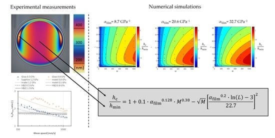
Prediction of minimum film thickness is often used in practice for calculation of film parameter to design machine operation in full film regime. It was reported several times that majority of prediction formulas cannot match experimental data in terms of minimum film thickness. These standard prediction formulas give almost constant ratio between central and minimum film thickness while numerical calculations show ratio which spans from 1 to more than 3 depending on M and L parameters. In this paper, an analytical formula of this ratio is presented for lubricants with various pressure–viscosity coefficients. The analytical formula is compared with optical interferometry measurements and differences are discussed. It allows better prediction, compared to standard formulas, of minimum film thickness for wide range of M and L parameters.

Graphical Abstract

1. Introduction

Prediction of film thickness represents an important step necessary for up-to-date design of lubricated concentrated contact. Analytical prediction formula can provide simple and rapid estimate of film thickness in elastohydrodynamically lubricated (EHL) contact. Minimum film thickness is used for calculation of film parameter to judge if machine will operate in full or mixed lubrication regime.
Since the pioneering work of Hamrock–Dowson in 1977 [1], numerous prediction formulas have been published in the literature [2,3,4,5,6]. An overview of the prediction formulas can be found in References [7,8,9]. A common approach is to make full numerical simulations of a contact for some range of conditions and solve regression analysis of film thickness results on operating conditions. These regressions were proven to be surprisingly accurate (considering the time of original formulation), if conditions of contact inlet are isothermal Newtonian. This is especially true for central film thickness, but generally not the case of minimum film thickness [10,11,12,13,14].
Several authors have showed that the ratio between central and minimum film thickness vary significantly with operating parameters [5,15,16,17]. Moreover, trend of the ratio is not monotonous depending on L parameter, i.e., reaching a local maximum at some value of L parameter. Classic prediction formula defined as a power function of operating conditions cannot represent such phenomenon. For better minimum film thickness formula, it is necessary to search for analytical form that can describe the ratio between central and minimum film thickness. Recently, a parameterization for the ratio of central to minimum film thickness was found for slender contacts (contact size in entrainment direction is much larger than in perpendicular direction) [18].
In this paper, the ratio between central film thickness and minimum film thickness is studied depending on M and L dimensionless parameters. New analytical formula allowing rapid prediction of minimum film thickness in circular point contact is suggested based on numerical simulations. The new formula is compared to ratio that come from Hamrock–Dowson equations and optical interferometry measurements.

2. Material and Methods

2.1. Numerical Calculations

An isothermal Newtonian numerical solution of elastohydrodynamically lubricated (EHL) point contact is assumed. Mathematical model consists of Reynolds equation
x ( ρ h 3 12 η p x ) + y ( ρ h 3 12 η p y ) u ( ρ h ) x = 0
with boundary conditions p(xa, y) = p(xb, y) = p(x, ya) = p(x, yb) = 0 and the cavitation condition p(x, y) ≥ 0, film thickness equation
h ( x ,   y ) = h 0 + x 2 2 R x + y 2 2 R y + 2 π E r p ( x , y ) d x d y ( x x ) 2 + ( y y ) 2
and force balance equation
F = p ( x , y ) d x   d y
Roelands pressure–viscosity and Dowson–Higginson pressure–density relations have been considered
η ( p ) = η 0 exp [ ( ln η 0 + 9.67 ) ( ( 1 + p 0.196 · 10 9 ) Z 1 ) ]
Z = α 0 · 0.196 · 10 9 ln η 0 + 9.67
ρ ( p ) = ρ 0 5.9 · 10 8 + 1.34 p 5.9 · 10 8 + p
The mathematical model in Equations (1)–(3) was solved by the multilevel multi-integration technique [19]. Second order discretization was assumed. Several mashes with number of grid points from 129 × 129 to 1025 × 1025 were used and differences between results were monitored to ensure results free of significant grid effect.
Pressure–viscosity response is important for film forming capability of a contact, which is described well by reciprocal asymptomatic isoviscous pressure coefficient α* or film pressure–viscosity coefficient αfilm which is proportional to the α* evaluated up to maximum inlet zone pressure [20]. This pressure is, according to Bair et al. [20], considered to be equal to 3/α*.
α * = [ 0 p η 0   d p η ( p ) ] 1
α film = α * [ 1 exp ( 3 ) ]
The αfilm pressure–viscosity parameter is used in the present analytical model of central to minimum film thickness ratio.

2.2. Film Thickness Measurement

Film thickness measurements were done on a custom developed ball-on-disk optical tribometer (Brno University of Technology, Brno, Czech republic) [12]. This device measures film thickness in an elastohydrodynamic contact between steel ball and glass (sapphire) disk based on optical interferometry principle. Interferograms are formed between light beams reflected from a ball surface and bottom side of the glass (sapphire) disk coated by thin layer of chromium to ensure high interference contrast. Interferograms are evaluated by Thin film colorimetric interferometry. The measurement method uses robust calibration procedure which establishes film thickness/color calibration from monochromatic and chromatic interferogram of a static contact. The calibration procedure and method are described in References [21,22]. The present configuration is without spacer layer which enables evaluation of film thickness in a range of 0–800 nm with resolution better than 1 nm.
Film thickness was measured for steel on glass and steel on sapphire configurations with reference fluid tri (2-ethylhexyl) trimellitate (TOTM, Sigma–Aldrich, Darmstadt, Germany) as a lubricant. Rheological properties of this fluid were measured in [23]. Basic rheology parameters for test temperature are in Table 1. Temperature was measured in contact inlet by thermocouple calibrated to more accurate thermistor sensor. Properties of contact bodies are in Table 2.

3. Results and Discussion

A series of EHL contacts with parameters listed in Table 3 were numerically simulated. A convergence better than 10−4 was required. The ratio of central to minimum film thickness hc/hmin was evaluated. Contact simulations were done on square grids with different number of points in a range from 129 × 129 to 1025 × 1025. A difference between results on coarse and finer meshes were evaluated and accepted only when data were with relative difference < 1% for M < 750 and < 3% for M ≥ 750 to ensure they were free of mesh density influence. All calculated data of ratios are listed in the Table A1, Table A2 and Table A3.
Film thickness ratios were compared to published results in [17,18]. The average difference (Table 4) is 4.4% and 3.5%, respectively. Because it was found in present results that film thickness ratio depends on pressure–viscosity coefficient, besides M and L parameters, certain part of the deviations can come from differences in this coefficient. The values of pressure–viscosity, for which the film thickness ratios were obtained, are not clear in the literature sources.
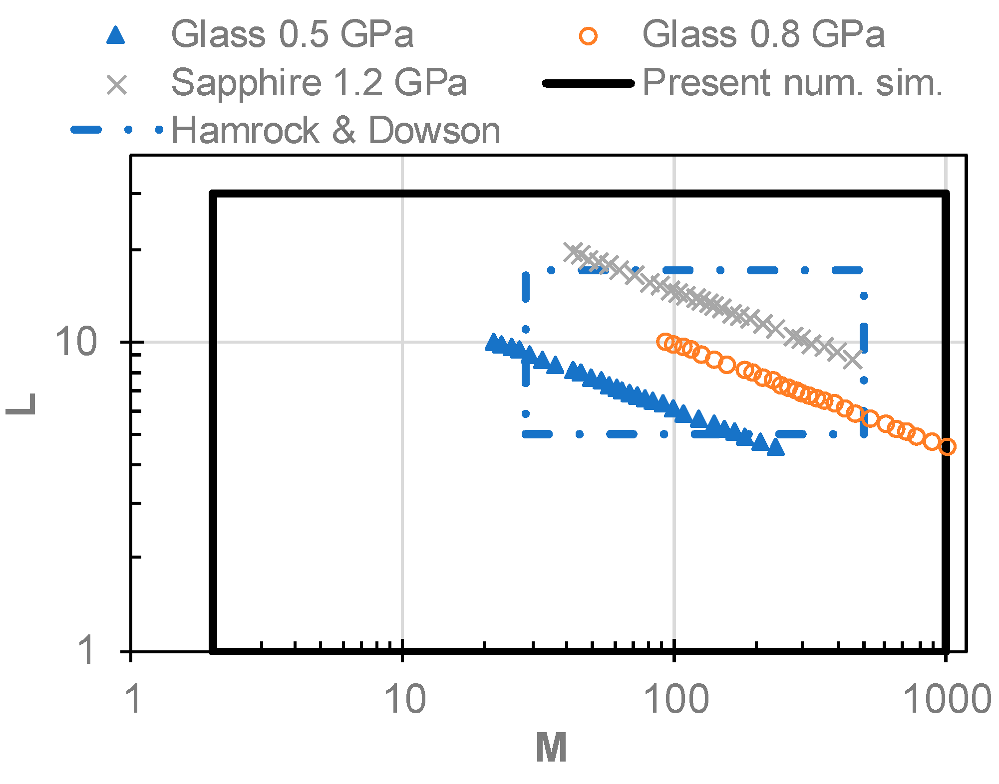
Figure 1 shows a domain of current simulations, operating points of experiments and domain of parameters on which Hamrock–Dowson film thickness equations were established. These equations are one of the most employed in EHL field, therefore, it was chosen for comparison. According to [1], the central and minimum film thickness can be predicted by
h c = 2.69 R x U 0.67 G 0.53 W 0.067 [ 1 0.61 e 0.73 k ]
h min = 3.63 R x U 0.68 G 0.49 W 0.073 [ 1 e 0.68 k ]
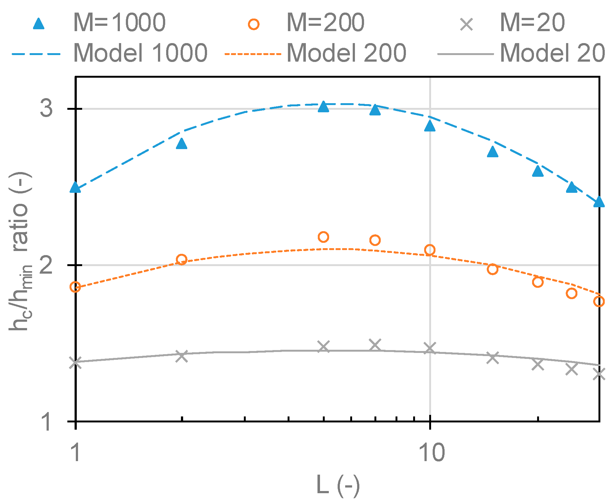
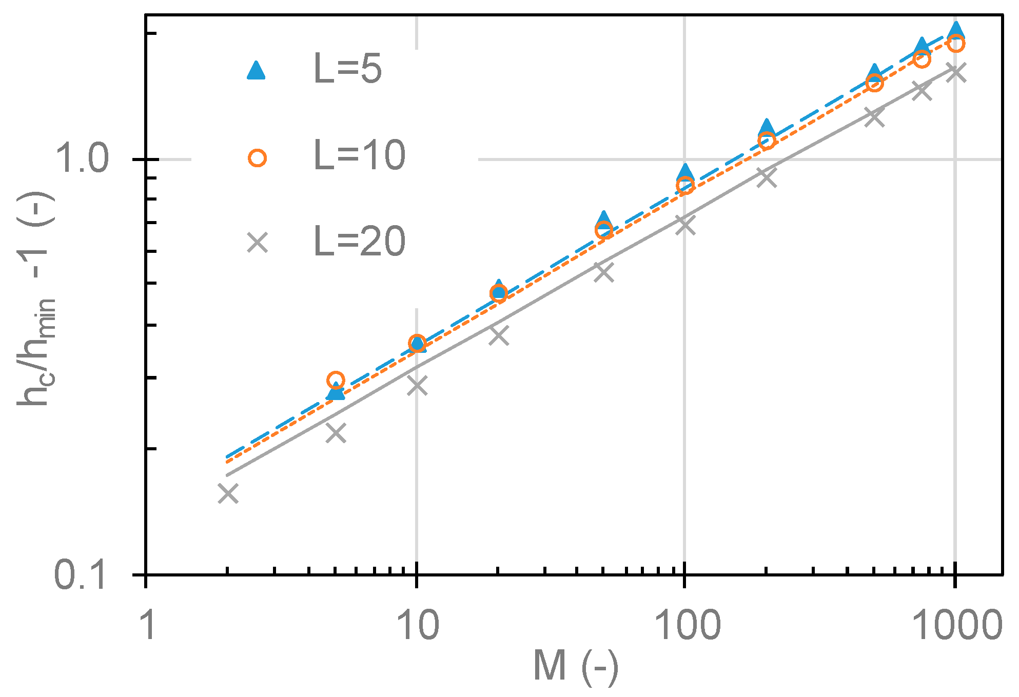
Figure 2 shows a dependency of film thickness ratio hc/hmin−1 on M parameter for three fixed L values. Figure 3 presents a dependency of film thickness ratio hc/hmin on L parameter for three fixed M values. Both plots are for αfilm = 20.6 GPa−1. The dependency of the film thickness ratio monotonically rises on M while there is a local maximum in dependency on parameter L. This local maximum is around L = 5 and seems to slightly change with increasing M parameter. The ratio approaches 1 for low L and M values.
Since axes in Figure 2 are in log scale, the points follow power trend with parameter M. When x axis in Figure 3 is transformed to log scale, the points follow close to quadratic trend. Therefore, the complete dataset was fitted to Equation (11), where a, b, c and d are fitting constants.
h c h min = 1 + a · M b M [ c · ln ( L ) d ] 2
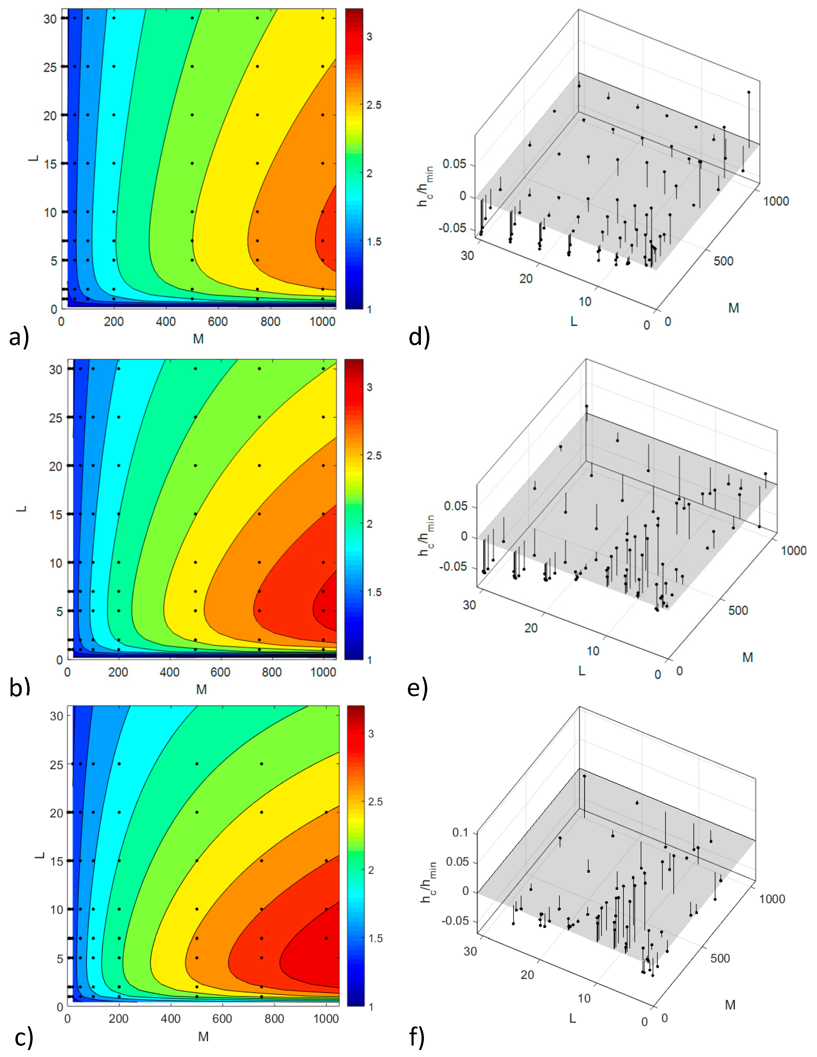
The effect of different reduced radii of curvature, elastic properties or lubricant ambient viscosity on the ratio was checked by numerical simulations and no effect was found; therefore, the results are considered independent of chosen geometry and elasticity. On the other hand, it was found that film thickness ratio is sensitive to pressure–viscosity coefficient; simulations were done for three values (Table 3) in a range from 8.7 to 32.7 GPa−1. It corresponds to the pressure–viscosity coefficient according definition in Equation (8) published by Bair [23]. It was shown that it is able precisely capture relation of viscosity on pressure necessary for film thickness formation in EHL contacts. According Table 3, the values of αfilm are not far from α* coefficient. The analytical model fitted to the results is shown in Figure 4 in a form of contour plot on the left side and residuals from fitting in the right plots. Final form of analytical model of film thickness ratio which depends on M and L parameters and αfilm pressure–viscosity coefficient is given by Equation (12). Quality parameters of the fits shown in Figure 4 are listed in Table 5; root mean square of the error is 0.03–0.04 which represents about 2% of average film thickness ratio. Equation (12) was plotted as a model in Figure 2, Figure 3, Figure 4 and Figure 5.
h c h min = 1 + 0.1 · α film 0.128 · M 0.38 M [ α film 0.2 · ln ( L ) 3 22.7 ] 2
where αfilm is in GPa−1. The equation is repeated together with list of assumptions and conditions for which it was obtained in Appendix B.
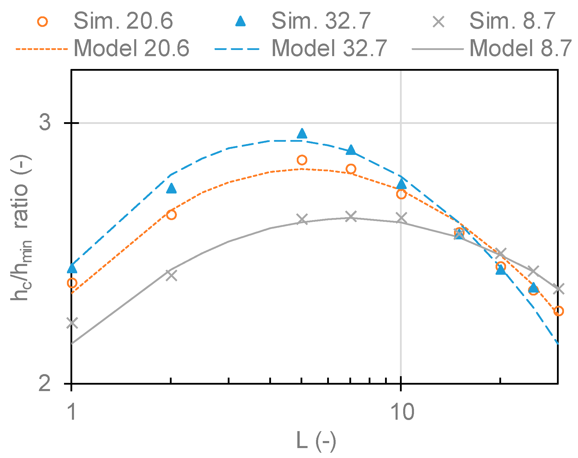
According Equation (12) and Figure 2, the pressure–viscosity coefficient modifies constant in power trend on M parameter, but the power slope remains the same. In terms of dependency on L parameter, the pressure–viscosity coefficient shifts the position of maximum peak, as it is shown in Figure 5.
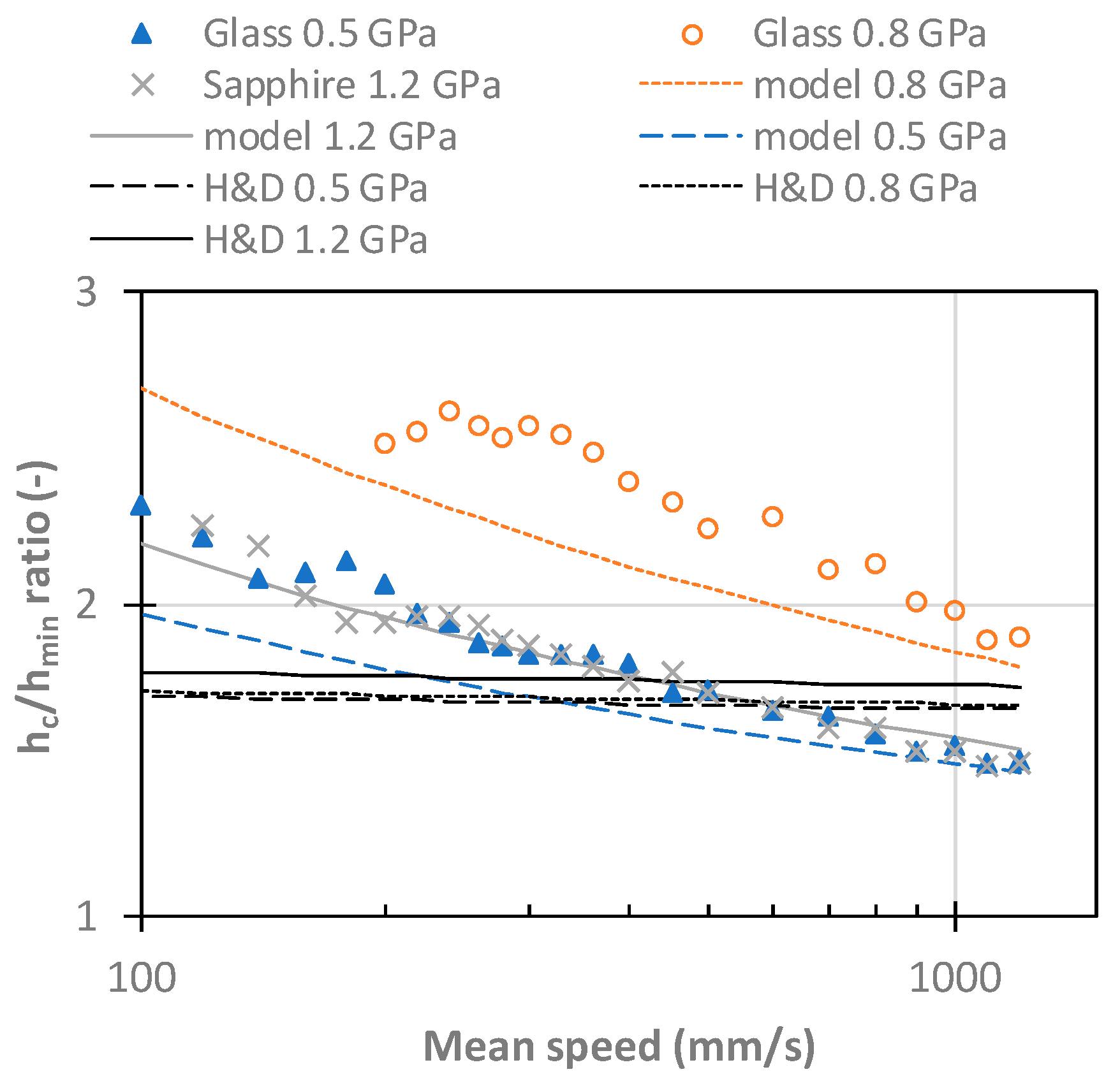
Next to the simulations, a film thickness was measured at three levels of Hertzian pressure. It was a contact of steel against glass for 26 and 112 N giving Hertzian pressure of 0.493 and 0.799 GPa, respectively, and a contact of steel with sapphire loaded by 63 N giving 1.186 GPa. Central film thickness was evaluated and corrected for refractive index change with pressure, as in [10], while minimum film thickness was left without correction since the place of minimum is expected to be in the area of low pressure. A range of speeds from 100 to 1200 mm/s was measured and hc/hmin ratio was calculated.
In Figure 6, there is a comparison of measured ratios with predictions given by present model (Equation (12)) and prediction according Hamrock–Dowson formulas (Equations (9) and (10)). The Hamrock–Dowson formulas gives almost constant hc/hmin ratio which is close to measured value only for 0.5 and 1.2 GPa and small range of speed around 500 mm/s. Present model gives good prediction of trends in all cases. Quantitatively, there is very good agreement for 1.2 GPa and not as good agreement for 0.5 and 0.8 GPa. Average differences between measurement and predictions are listed in Table 6. It shows that present formula predicts the ratio within 11%, while Hamrock–Dowson is off by up to 37%.
Ratios calculated from measured data having uncertainties can produce a large error when thin films are studied. Therefore, conditions with hmin film thickness above 60 nm and hc film thickness above 140 nm were considered. Measurements were repeated three times for each pressure; ratios were evaluated independently and averaged. Average standard deviation of measured ratios is 0.028 which corresponds to 1.3%. Measurement has another error which comes from the fact that minimum film thickness is evaluated as a global minimum in a contact. Every ball has a certain roughness (3 nm RMS in present measurement); therefore, the evaluated hmin is practically always picked on a peak of roughness. As a result, measured minimum film thickness tends to be systematically evaluated as lower than the true value. Typical in-contact RMS value of roughness was 0.6 nm, therefore, distance of mid plane to highest peaks was about 1.8 nm which makes average impact on film thickness ratio 0.03, i.e., much less then observed difference.
As shown in Figure 3 and Figure 5, present model (Equation (12)) cannot fully capture the highest values of simulated ratios. The highest fit residuals are between L parameter 5 and 7 where experimental conditions of 0.5 and 0.8 GPa are localized (see Figure 1). Nevertheless, these local residuals of the fit are up to 0.08, thus they cannot fully explain differences in measurements.
In present study, Roelands model for pressure–viscosity relationship and Dowson–Higginson relation of density dependency on pressure were used. These models have limitations. Various lubricants can behave differently, especially under high pressure. Nevertheless, it is commonly expected that low pressure rheology is important for film forming capabilities. Furthermore, real lubricant compressibility influences central film thickness, which affects the film thickness ratio.
4. Conclusions

The ratio between central and minimum film thickness in a circular EHL contact varies between 1 and 3.16 for considered range of conditions. This trend cannot be captured by widely used prediction formulas employing (monotonous) power function, since dependency on L parameter has a local extreme at L = exp(3/αfilm0.2). Isothermal Newtonian numerical simulations were used to compute the film thickness ratio for wide range of M and L parameters and three pressure–viscosity coefficients. A new analytical formula for fitting of the ratio is presented. Final regression of numerical simulations has root mean square error of 0.036, i.e., 1.9%. A comparison with measurement showed good trend agreement and quantitatively smaller difference than Hamrock–Dowson formulas. This new formula together with published formula for central film thickness can be used for minimum thickness prediction.

Author Contributions

P.S. conducted experiments and calculated simulation data; P.S. and I.K. analyzed the data; I.K. and M.H. developed measurement method, provided consultation of results and obtained funding for research; P.S. wrote the paper.

Funding

This research was funded by the Ministry of Education, Youth and Sports under the National Sustainability Program I (Project LO1202).

Conflicts of Interest

All authors declare no conflict of interest.

Nomenclature

a, b, c, dfitting constants of analytical model, Equation (10)
Erreduced elastic modulus, 2/[(1 − υ12)/E1+(1 − υ22)/E2]
Fload
Gmaterial parameter, αE
hfilm thickness, hc (central), hmin (minimum)
kcontact ellipticity ratio
MMoes parameter, G(2U)0.25
LMoes parameter, W(2U)−0.75
Ppressure
r1x,r2xradii of curvature of surface 1 and 2 in x-direction
Rxreduced radius of curvature in x-direction, r1xr2x/(r1x + r2x)
Ryreduced radius of curvature in y-direction, r1yr2y/(r1y + r2y)
umean speed
Uspeed parameter, η0u/E’Rx
Wload parameter, F/E’Rx2
x, ycomputational domain coordinates (xa, xb, ya, yb—boundaries of the domain)
α0initial pressure–viscosity coefficient of lubricant
α*reciprocal asymptomatic isoviscous pressure coefficient
αfilmfilm pressure–viscosity coefficient
ρlubricant density
ρ0lubricant density at ambient pressure
ηlubricant viscosity
η0lubricant viscosity at ambient pressure

Appendix A. Simulation Data

Table A1. Ratios of central film thickness to minimum film thickness in a point contact for αfilm = 8.7 GPa−1.
M
251020501002005007501000
L11.241.351.361.481.611.792.082.232.35
21.241.341.381.531.701.902.242.412.55
51.231.311.401.591.782.012.412.632.77
71.231.301.401.601.792.032.432.642.81
101.231.291.401.591.782.022.422.632.80
151.141.211.281.381.561.741.972.362.572.74
201.131.191.261.361.531.701.922.302.502.65
251.121.181.251.341.501.661.872.232.432.58
301.101.171.241.321.481.631.832.172.362.50
Table A2. Ratios of central film thickness to minimum film thickness in a point contact for αfilm = 20.6 GPa−1.
M
251020501002005007501000
L11.251.371.391.521.671.872.202.382.50
21.251.371.421.611.812.042.432.642.78
51.281.361.491.711.932.182.622.853.02
71.301.371.491.711.922.172.602.823.00
101.291.361.471.671.862.102.512.732.90
151.191.251.321.421.591.771.982.372.582.73
201.161.221.291.381.531.691.902.252.452.61
251.141.201.261.341.491.641.832.172.362.51
301.181.241.311.451.591.782.102.282.42
Table A3. Ratios of central film thickness to minimum film thickness in a point contact for αfilm = 32.7 GPa−1.
M
251020501002005007501000
L11.251.371.401.541.701.902.252.44
21.261.381.441.651.862.112.522.75
51.301.391.531.771.992.272.722.96
71.331.401.531.761.972.232.672.893.09
101.321.391.511.701.902.132.542.772.95
151.211.271.341.441.611.781.992.372.572.73
201.181.241.331.411.541.701.902.242.442.59
251.351.511.641.832.152.37

Appendix B. Film Thickness Ratio Equation and Table with Assumptions

h c h min = 1 + 0.1 · α film 0.128 · M 0.38 M [ α film 0.2 · ln ( L ) 3 22.7 ] 2
where αfilm is in GPa−1. This equation was obtained under contact assumptions and for the range of conditions listed in the following Table A4.
Table A4. List of contact assumptions and the range of conditions in the numerical analyses.
Isothermal Newtonian (without shear thinning effects) conditions
Circular point contact
Smooth surface
Lubricant rheology governed by Roelands pressure–viscosity and Dowson–Higginson pressure–density relationships
M parameter from 2 to 1000
L parameter from 1 to 30
Pressure–viscosity coefficient αfilm from 8.7 to 32.7 GPa−1

References

  1. Hamrock, B.J.; Dowson, D. Isothermal elastohydrodynamic lubrication of point contacts: Part III—Fully flooded results. J. Lubr. Technol. 1977, 99, 264–275. [Google Scholar] [CrossRef]
  2. Evans, P.; Snidle, R. The isothermal elastohydrodynamic lubrication of spheres. ASME J. Lubr. Technol. 1981, 103, 547–557. [Google Scholar] [CrossRef]
  3. Chittenden, R.J.; Dowson, D.; Dunn, J.F.; Taylor, C.M. A theoretical analysis of the isothermal elastohydrodynamic lubrication of concentrated contacts—Part 2: General case, with lubricant entrainment along either principal axis of the hertzian contact ellipse or at some intermediate angle. Proc. R. Soc. Lond. A 1985, 397, 271–294. [Google Scholar] [CrossRef]
  4. Hooke, C.J. Minimum film thickness in lubricated point contacts operating in the elastic piezoviscous regime. Proc. Inst. Mech. Eng. Part C J. Eng. Tribol. 1988, 202, 73–84. [Google Scholar]
  5. Nijenbanning, G.C.H.H.; Venner, C.H.; Moes, H. Film thickness in elastohydrodynamically lubricated elliptic contacts. Wear 1994, 176, 217–229. [Google Scholar] [CrossRef] [Green Version]
  6. Masjedi, M.; Khonsari, M.M. On the effect of surface roughness in point-contact EHL: Formulas for film thickness and asperity load. Tribol. Int. 2015, 82, 228–244. [Google Scholar] [CrossRef]
  7. Van Leeuwen, H. The determination of the pressure–viscosity coefficient of a lubricant through an accurate film thickness formula and accurate film thickness measurements. Proc. Inst. Mech. Eng. Part J J. Eng. Tribol. 2009, 223, 1143–1163. [Google Scholar] [CrossRef]
  8. Van Leeuwen, H. The determination of the pressure–viscosity coefficient of a lubricant through an accurate film thickness formula and accurate film thickness measurements. Part 2: High L values. Proc. Inst. Mech. Eng. Part J J. Eng. Tribol. 2011, 225, 449–464. [Google Scholar] [CrossRef]
  9. Wheeler, J.D.; Vergne, P.; Fillot, N.; Philippon, D. On the relevance of analytical film thickness EHD equations for isothermal point contacts: Qualitative or quantitative predictions? Friction 2016, 4, 369–379. [Google Scholar] [CrossRef] [Green Version]
  10. Krupka, I.; Hartl, M.; Poliscuk, R.; Cermak, J.; Liska, M. Experimental evaluation of EHD film shape and its comparison with numerical solution. J. Tribol. 2000, 122, 689–696. [Google Scholar] [CrossRef]
  11. Krupka, I.; Hartl, M.; Poliscuk, R.; Liska, M. Experimental study of central and minimum elastohydrodynamic film thickness by colorimetric interferometry technique. Tribol. Trans. 2000, 43, 611–618. [Google Scholar] [CrossRef]
  12. Hartl, M.; Krupka, I.; Poliscuk, R.; Liska, M.; Molimard, J.; Querry, M.; Vergne, P. Thin film colorimetric interferometry. Tribol. Trans. 2001, 44, 270–276. [Google Scholar] [CrossRef]
  13. Křupka, I.; Hartl, M.; Liška, M. Influence of contact pressure on central and minimum film thickness within ultrathin film lubricated contacts. J. Tribol. 2005, 127, 890–892. [Google Scholar] [CrossRef]
  14. Biboulet, N.; Sperka, P.; Venner, C.H.; Lubrecht, A.A.; Krupka, I. Obtaining the pressure spike and maximum shear stress from optical interferometry data. Tribol. Int. 2013, 62, 1–7. [Google Scholar] [CrossRef]
  15. Venner, C.H. Multilevel Solution of the EHL Line and Point Contact Problems. Ph.D. Thesis, Twente University, Enschede, The Netherlands, 1991. [Google Scholar]
  16. Venner, C.H.; Napel, W.E. Multilevel solution of the elastohydrodynamically lubricated circular contact problem, part II: Smooth surface results. Wear 1992, 152, 369–381. [Google Scholar] [CrossRef]
  17. Chaomleffel, J.P.; Dalmaz, G.; Vergne, P. Experimental results and analytical predictions of EHL film thickness. Tribol. Int. 2007, 40, 1543–1552. [Google Scholar] [CrossRef]
  18. Venner, C.H.; Lubrecht, A.A. Revisiting film thickness in slender elasto-hydrodynamically lubricated contacts. Proc. Inst. Mech. Eng. Part C J. Eng. Tribol. 2010, 224, 2549–2558. [Google Scholar] [CrossRef]
  19. Venner, C.H.; Lubrecht, A.A. Multi-Level Methods in Lubrication; Elsevier: Amsterdam, The Netherlands, 2000. [Google Scholar]
  20. Bair, S.; Liu, Y.; Wang, Q.J. The pressure–viscosity coefficient for Newtonian EHL film thickness with general piezoviscous response. J. Tribol. 2006, 128, 624–631. [Google Scholar] [CrossRef]
  21. Hartl, M.; Krupka, I.; Liska, M. Differential colorimetry: Tool for evaluation of chromatic interference patterns. Opt. Eng. 1997, 36, 2384–2391. [Google Scholar] [CrossRef]
  22. Hartl, M.; Krupka, I.; Poliscuk, R.; Liska, M. An automatic system for real-time evaluation of EHD film thickness and shape based on the colorimetric interferometry. Tribol. Trans. 1999, 42, 303–309. [Google Scholar] [CrossRef]
  23. Bair, S. The temperature and pressure dependence of viscosity and volume for two reference liquids. Lubr. Sci. 2016, 28, 81–95. [Google Scholar] [CrossRef]
Figure 1. Present calculation domain compared to operating points of experiments and domain for regression of Hamrock–Dowson formulas.
Lubricants 06 00080 g001
Figure 2. Dependency of hc/hmin ratio on M parameter for αfilm = 20.6 GPa−1.
Lubricants 06 00080 g002
Figure 3. Dependency of hc/hmin ratio on L parameter for αfilm = 20.6 GPa−1.
Lubricants 06 00080 g003
Figure 4. Numerical results of film thickness ratio hc/hmin fitted by analytical function: (ac) contours plots; and (df) fitting residuals ((a,d) for αfilm = 8.7 GPa−1; (b,e) for αfilm = 20.6 GPa−1; and (c,f) αfilm = 32.7 GPa−1).
Lubricants 06 00080 g004
Figure 5. Dependency of hc/hmin ratio on L for M = 750 and all three simulated αfilm.
Lubricants 06 00080 g005
Figure 6. Comparison of measured hc/hmin ratios with prediction from Hamrock–Dowson equations (Equations (8) and (9)) and present analytical model given by Equation (12).
Lubricants 06 00080 g006
Table 1. Lubricant parameters.
TOTM
Test temperature30 ± 0.5 °C
Ambient viscosity0.1517 Pa·s
Initial pressure–viscosity coefficient α023.9 GPa−1
Pressure–viscosity coefficient α*21.5 GPa−1
Film pressure–viscosity coefficient αfilm20.9 GPa−1
Table 2. Properties of contact bodies.
SteelGlassSapphire
Radius of curvature12.7 mm
Young modulus206 GPa81 GPa405 GPa
Poisson’s ratio0.30.2090.25
Table 3. Range of numerically simulated conditions.
MLα0α*αfilm
2, 5, 10, 20, 50, 100, 200, 500, 750, 10001, 2, 5, 7, 10, 15, 20, 25, 3011, 22, 33 GPa−18.2, 20.3, 32.6 GPa−18.7, 20.6, 32.7 GPa−1
Table 4. Comparison of present hc/hmin results to published ones.
Comparison 1Comparison 2Comparison 3
Published resultVenner [18]Venner [18]Chevalier [17]
Present resultnumerical resultsanalytical modelanalytical model
Average difference4.4%4.3%3.5%
Table 5. Parameters of fitting goodness.
αfilm8.7 GPa−120.6 GPa−132.7 GPa−1
Root mean square error (RMSE)0.0310.0380.039
RMSE in %1.7%2.0%2.1%
Table 6. Average difference of measurement and hc/hmin ratio estimation by Hamrock–Dowson (H&D) and present analytical formula.
Case 1Case 2Case 3
Measurement pressure0.5 GPa0.8 GPa1.2 GPa
H&D formulas (Equations (9) and (10))12.9%36.5%9.7%
Present formula (Equation (12))8.8%10.6%2.2%