Article

Cavitation Growth Phenomena in Pure-Sliding Grease EHD Contacts

1
Division of Mechatronics, Department of Innovative Engineering, Faculty of Science and Technology, Oita University, 700 Dannoharu, Oita 870-1192, Japan
2
Department of Engineering and Design, University of Sussex, Brighton BN1 9RH, UK
3
International Institute for Carbon-Neutral Energy Research, Kyushu University, Fukuoka 819-0395, Japan
*
Author to whom correspondence should be addressed.
Lubricants 2018, 6(3), 75; https://doi.org/10.3390/lubricants6030075
Submission received: 14 July 2018 / Revised: 17 August 2018 / Accepted: 20 August 2018 / Published: 22 August 2018
(This article belongs to the Special Issue Fluid-Film Lubrication)

Abstract

:
This article describes experimental and theoretical studies on the cavitation phenomena in the grease lubrication film under pure sliding elastohydrodynamic contact. In situ observation tests using the optical interferometry technique were conducted, and the growth of cavitation was captured using a high-speed camera. The results showed that the cavity grew in two stages, which was similar to the behavior in the base oil, and that the cavity growth rate in the initial stage was higher than that in the second stage. In the initial stage, the cavity growth time in the grease was longer than that in the base oil, and the cavity length after the growth depended on the base oil viscosity. It was also found in the test using diurea grease that small cavities were formed by the lumps of thickener. The cavity growth in the initial stage was discussed by numerical simulation of pressure distribution based on a simple rheological model.

1. Introduction

Cavitation occurs in lubricated contact, and can be detrimental or beneficial to the performance of machine elements [1]. The phenomena related to cavitation include cavitation erosion, starvation, and breakdown of lubrication film in bearings, which are negative effects, but also reducing the friction coefficient and improving seal performance in seals and bearings, which are positive effects. Recently, the cavitation phenomena in the machine elements, such as journal bearing [2,3], seal [4], piston ring-cylinder liner [5,6], microtextured surface [7,8], have been studied by experimental observation and numerical simulation.
One of the negative actions is the inlet starvation which leads to breakdown of lubrication film. Nishikawa et al. [9] showed that short stroke length and/or large frequency in reciprocated motion can lead to severe starvation of the contact, due to cavitation. The outlet cavitation also affects the length of the meniscus at the inlet of contact in unidirectional rotating conditions [10,11]. Severe starvation is caused when the oil is not replenished into opened cavity area which is connected to the atmospheric air, before the next contact. In grease lubrication, the amount of replenishment into the cavity area is even smaller than that in the oil, because of the rheological properties of greases [12]. A combined, experimental and theoretical analysis of cavitation and fretting wear of a grease lubricated, a point elastohydrodynamic (EHD) contact test has been carried out by Leonard et al. [13]. Even at the low velocities characteristic to fretting contacts, they have observed gaseous cavitation, whose length extends with speed.
On the other hand, cavitation can reduce the friction coefficient in the lubrication film due to lower viscosity resistance force in the cavity region [14,15,16]. It has been reported by experimental approaches that cavities formed in the micro pit on the ring surface [16] and in the roughness on the rubber surface [17] are responsible for reducing the friction coefficient. The relationship between the sealing mechanism and cavitation in the lip [17] or face seals [4,18] is also known as positive actions. Anno and Walowit [19] reported that the load capacity on surfaces with micro-asperities is generated when cavitation occurs on the outlet of asperity, because the pressure in the cavitation region is constant and then the positive hydrodynamic pressure is greater than the negative one. This means that the lubrication performance of the sealing surfaces with a microtexture is improved by the formation of cavitation [4]. Cavitation also affects the pressure-induced flow of lubricant, which implies that the leakage of lubricant from the sealing system can be reduced by controlling the cavitation region [4]. From these facts it can be concluded that it is important to understand the behavior of cavitation in various working conditions for accomplishing safe and high performance machine components design.
Grease lubrication is widely used in many machine elements, especially rolling element bearings and constant velocity joints, where they are preferred to oil lubrication. They hold important advantages over oil lubricants such as lower lubricant losses, better corrosion protection, improved sealing, easy handling, and the elimination of complex and costly oil supply systems. Grease lubrication also has its disadvantages, such as poor heat convection, which leads to thermal degradation, and limited free flow, which leads to contact starvation. The complex nature of grease also makes it difficult to predict the film thickness in lubricated contacts from its rheological properties [20]. Extended studies have been carried out in the past on various aspects of grease-lubricated EHD contacts including the effect of thickener, the base oil, and the working parameters [21,22,23,24]. Kauzlarich and Greenwood [25] applied the Herschel-Bulckley flow equation to grease lubricated EHD contacts, carrying out a theoretical analysis of film. Yonggang and Jie [26] also started from the Herschel-Bulckley model of flow, and introduced a shear rate and time-dependent structural parameter.
It is expected that the cavitation phenomenon in grease-lubricated films to be different from that of oil lubrication films because of different rheology and flow properties. Cann et al. [27,28] reported that greases do not easily flow back onto the opened cavity area and the rolling track, thus, in the absence of other mechanisms by which the lubricant is brought back in the inlet, severe starvation of the contact occurs. Cavitation phenomena in grease lubrication have yet to be understood, especially the difference between cavitation in the base oil and the grease. Therefore it is important to investigate the cavitation phenomena in grease, for example the effect of rheological behavior and of the thickener, for the purpose of understanding their effect upon the lubrication performance.
One of the characteristics of cavitation is the growth phenomenon [29,30]. The authors have studied the cavity growth in oil lubricated point contacts in various environments [31,32]. It has been reported that the cavity grows in two stages, the initial stage in which the cavitation region shows rapid growth, and the second stage in which the growth rate is much lower than that in the first stage. The growth in the initial stage is not affected by the amount of dissolved gas in the oil, and the growth relates to the steep pressure drop generated at the outlet of the conjunction. The growth in the second stage depends on the amount of dissolved gas. The cavity length in a gas environment with higher gas solubility is longer, because the amount of released gas into the cavity is affected by the dissolved gas in the oil. It has also been shown in the previous study that this cavity growth model is applied in the high temperature and low pressure conditions [33,34,35].
In this study, growth of the cavity in grease lubricated point contacts in pure sliding is investigated. The difference of cavitation phenomena between the grease and the base oil, and the effect of grease composition on the cavity growth are also discussed in this paper. In order to understand the effect of the rheological properties of the greases on cavity growth, a simple numerical analysis was conducted.

2. Experimental

2.1. Test Apparatus

Figure 1 shows a rig for measuring EHD film thickness by optical interferometry used in this study. Greases and their base oils were tested in pure sliding, elastohydrodynamic point contact at a room temperature of 295 K. A plano convex lens was pressed against a rotating disc by a lever, not shown in the figure. The contact between the disc and the lens and the surrounding area were observed through a custom built microscope, and interferometric images of the contact were recorded with a high speed CCD camera.
The disc was made of optical glass and had a coating of a semireflective chromium layer on the working side. The diameter and thickness of the disc were 80 and 8 mm, respectively. The optical interferometry technique with the spacer layer imaging method (SLIM) [36] was employed to evaluate the lubricant film thickness, and an additional layer of silica was deposited on top of the chromium coating. The lens was also made out of optical glass and was coated with fully-reflective chromium layer. The radius of curvature of the lens was 10.38 mm.
Two series of tests were conducted in this study. The first series consisted of pure sliding tests at 20 mm/s constant speed, in which a load of 1 N (maximum Hertzian pressures of 0.14 GPa, and contact diameter of about 120 μm) was applied to the contact while the disc rotates at a constant speed of 20 mm/s. The second series of experiments were carried out under the accelerating conditions. The speed at the point of contact was increased from rest to 46.5 mm/s, in 17 milliseconds, which gave an acceleration of 2.7 m/s2. In these tests, the load employed was 7 N, which produced a maximum Hertzian pressure of 0.27 GPa, and a contact diameter of about 226 μm.

2.2. Greases

Five greases were studied in this work. The properties of these greases are shown in Table 1. The base oil of the greases was poly-alpha-olefin (PAO) with various viscosities. Thickeners were lithium stearate, lithium hydroxystarate, and diurea. An amount of 0.2 mL of grease was uniformly spread onto the surface of the disc before each test. Grease or oil was not resupplied into the contact during the tests.

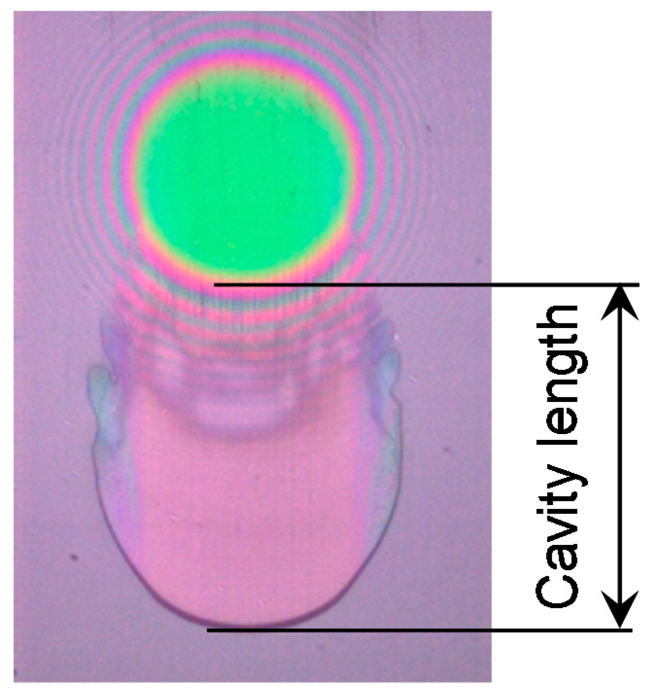
2.3. Definition of Cavity Length

Figure 2 shows an image of the contact and the surrounding area. The growth of cavity is described and analyzed in terms of cavity length which is defined as the length from the trailing edge of Hertzian contact to the trailing edge of the cavitation region, as shown in the figure.

3. Results and Discussion

3.1. Cavity Growth: Grease vs. Base Oil

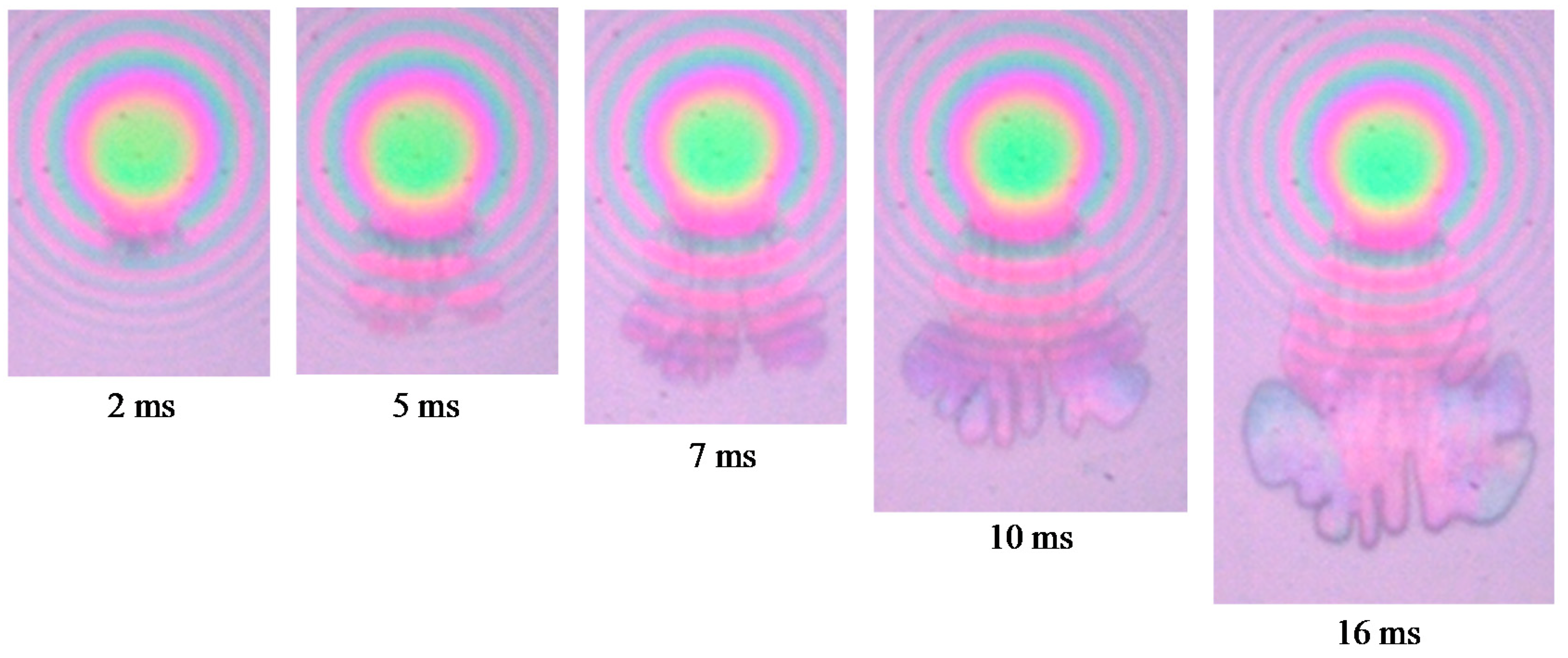
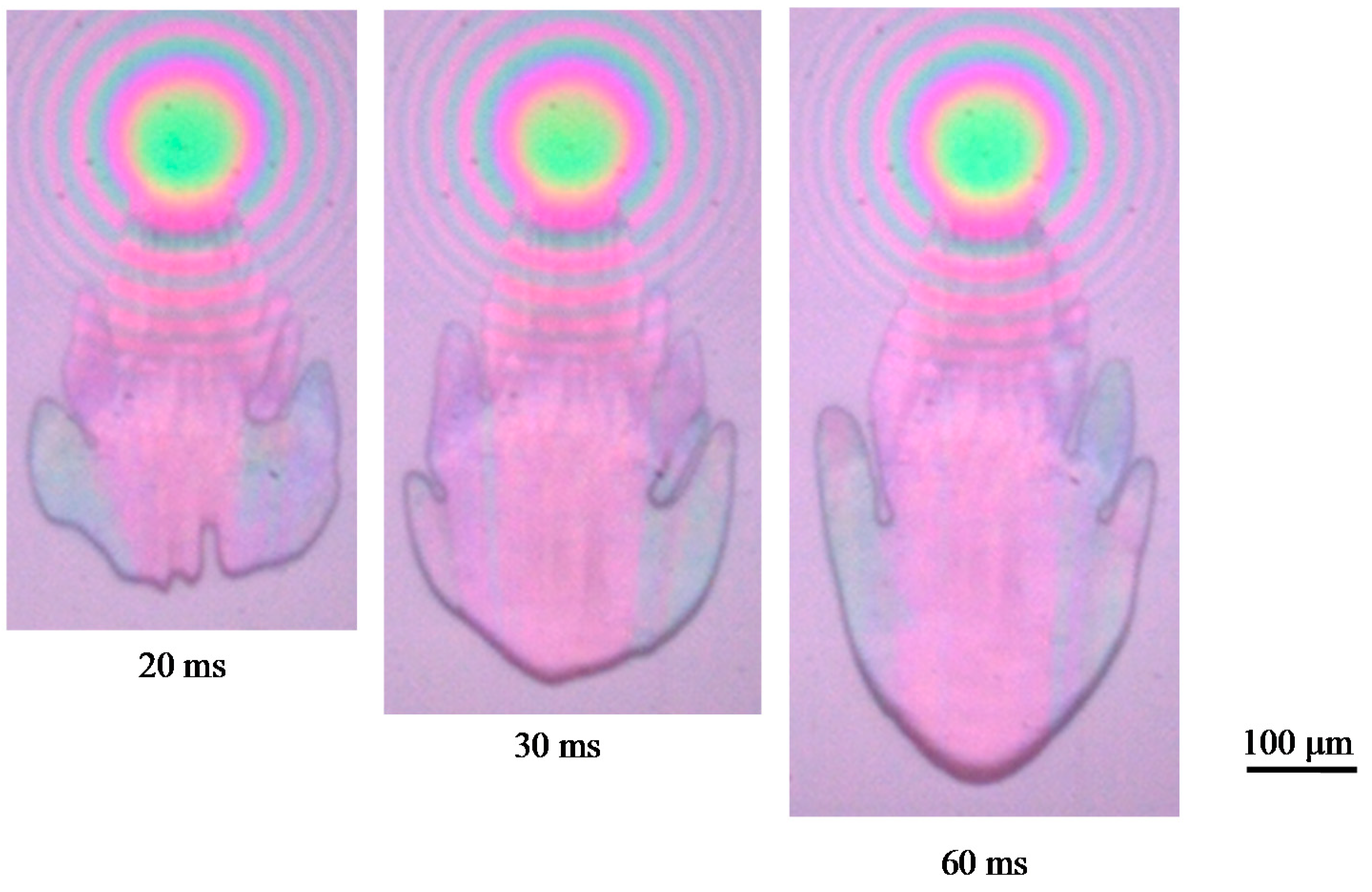
Figure 3 and Figure 4 show interferometric images of the contact including the cavitation region for lithium stearate grease (Grease 1, shown in Table 1) and its base oil, from the start of the motion and up to 60 ms when the cavity length has stabilized. The tests were conducted under constant speed condition. Here, the central film thicknesses of the grease and the base oil were about 17 and 23 nm, respectively, and the shear rate at the contact center were 1.2 × 10⁶ and 0.9 × 10⁶ s−1, respectively.
Figure 3 clearly illustrates that the cavitation region grows with time. In the image taken at 2 ms the initiation of cavity is observed at the exit of contact. The cavity at times ranging between 2 and 20 ms shows the distinctive flower petal-like shape which Dowson et al. [1] referred to as “fingers”. These “petals” appear at the trailing edge of the cavity, and subsequently grow with time. With this type of cavity shape, the gas dissolved in the lubricant is released into the cavity rapidly [32]. After about 30 ms the cavity shape changes to a rather rounded shape.
As seen in Figure 4, cavity growth for the base oil lubricated contact is similar to that of grease, that is the shape of the cavity soon after moving shows a petal-like shape, but this changes to a monotonic rounded shape after only 10 ms.
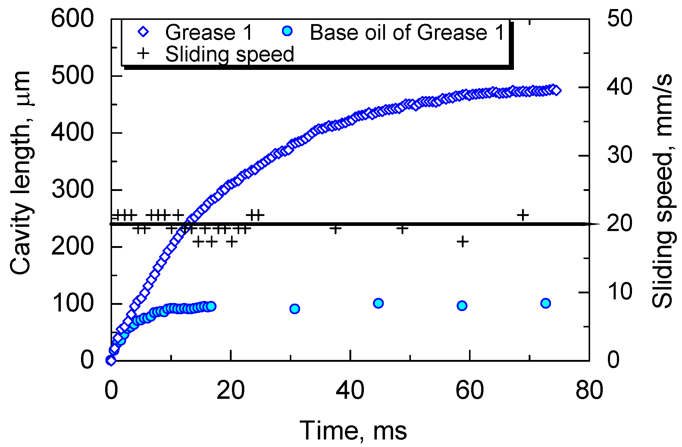
Figure 5 shows the changes in cavity length with time. The cavity in the grease lubricated contact grows rapidly for the first approximately 30–40 ms and the growth slows down markedly after that. In the case of the base oil, on the other hand, the cavity length increases rapidly for the first 5 ms at which point the growth rate decreases and cavity length stabilizes at about 10 ms. The growth rates up to 3 ms for the grease and the base oil are 25 and 20 mm/s, respectively. Thus, in the initial stage of the cavity growth after the initiation, the growth rate is close to the sliding speed of the contact of 20 mm/s for both the grease and the base oil. After this initial stage, the cavity length increases further at different rates, for the two types of lubricants.
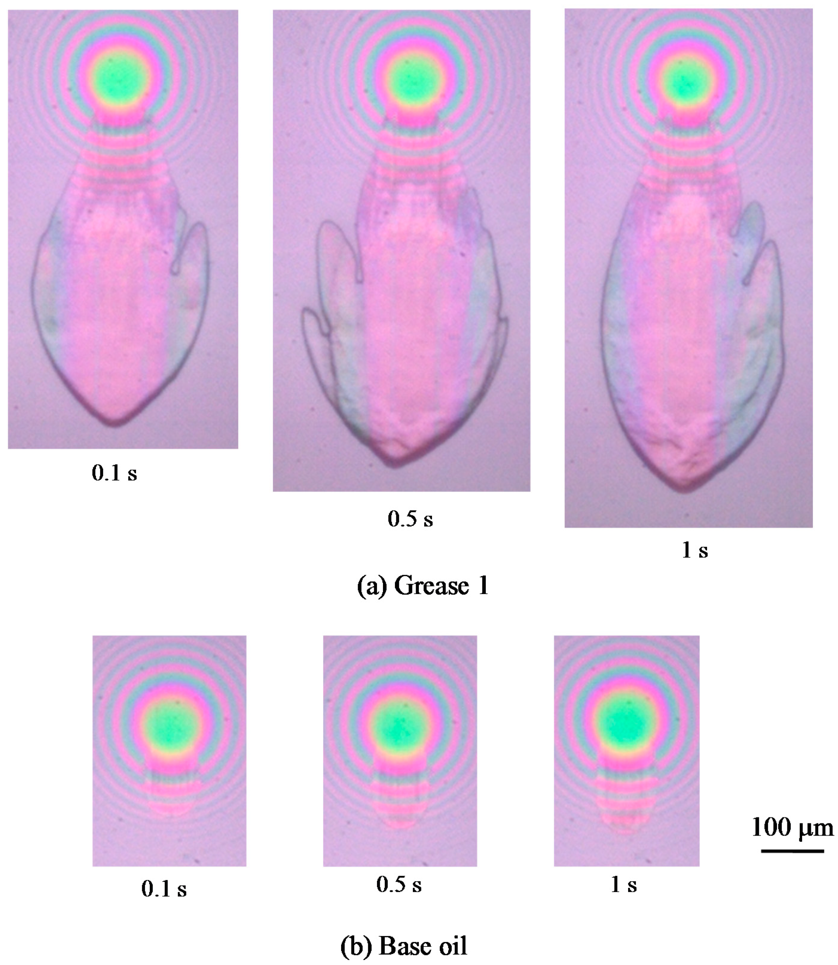
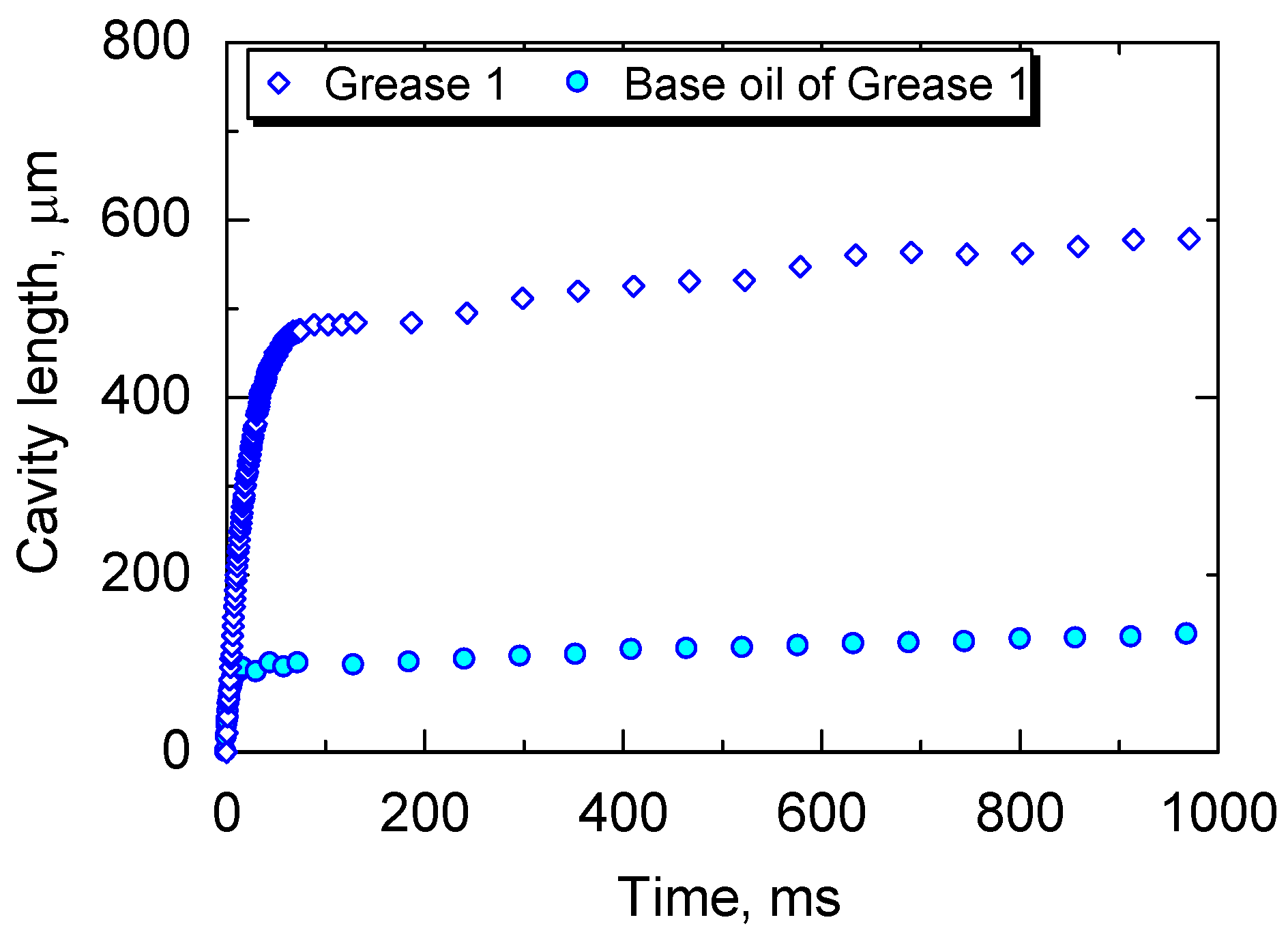
Figure 6 shows images of the cavitation region with lithium stearate grease (Grease 1) and its base oil at later stages from 0.1 to 1 s. Figure 7 shows changes in cavity length up to one second after the start. Figure 6 and Figure 7 demonstrate that the cavity grows gradually with time. Throughout the second stage, the growth rate of the grease is markedly higher than that in the base oil.
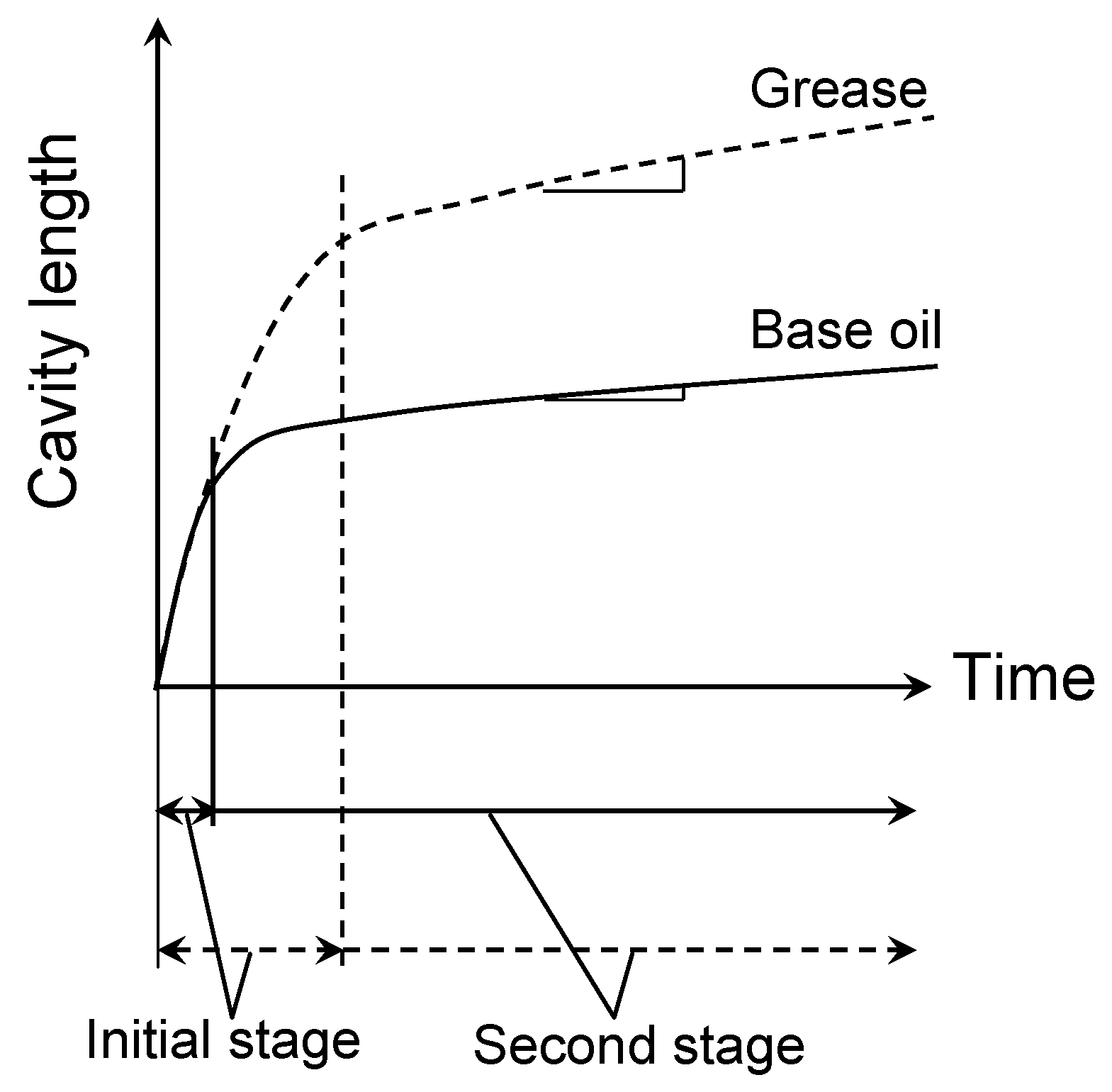
These results clearly show that the cavity in the grease film grows at two stages [32]. The initial growth occurs after the initiation of the cavity and takes place at a fast rate approximately equal to the sliding speed of the contact. The growth rates of the grease and the base oil are similar in this time region, but the time for this initial growth is longer for the grease. In the second stage, the cavity grows at a much slower rate, however the growth rate in the grease is still faster than that in the base oil. The details of the mechanism of growth phenomena will be discussed in the next section.

3.2. Effect of Base Oil Viscosity

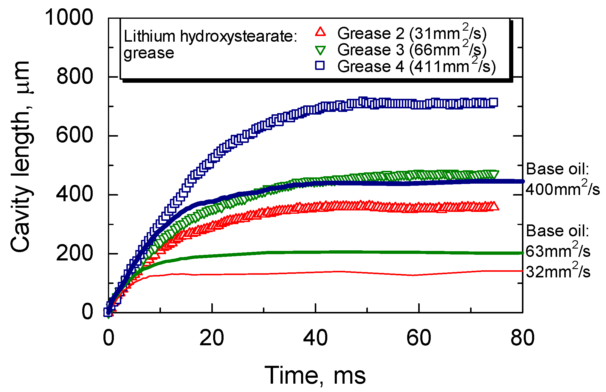
In Figure 8, the changes in the cavity length with time are shown for three lithium hydroxystearate greases with different base oil viscosity, 31, 66, and 410 mm2/s at 313 K (Grease 2, 3, and 4). The tests were conducted under constant speed condition. For comparison, changes of cavity length for the base oils are also shown.
The rate of cavity growth soon after the start is similar for greases with different base oil viscosity, but the duration in the initial stage is different; the time is longer for greases with higher base oil viscosity. At 60 ms after the initial growth, the cavity length is longer for greases with higher viscosity. Figure 8 also indicates that the cavity length at 60 ms for the base oil is shorter than that in the grease, while the growth rate in the initial stage is almost same for all the base oils and greases. Otsu [35] previously found that the cavity region in the initial stage was affected by the negative pressure generated at the outlet of the contact, and the cavity length increased with the viscosity because the negative pressure depends on the viscosity. Stadler et al. [37] also reported the relationship between the cavity length and the negative pressure. This behavior is almost the same as that found for the grease in this study. This suggests that the growth time increases with base oil viscosity because the negative pressure region is larger for higher viscosity; this also holds for the greases.

3.3. Effect of Thickener

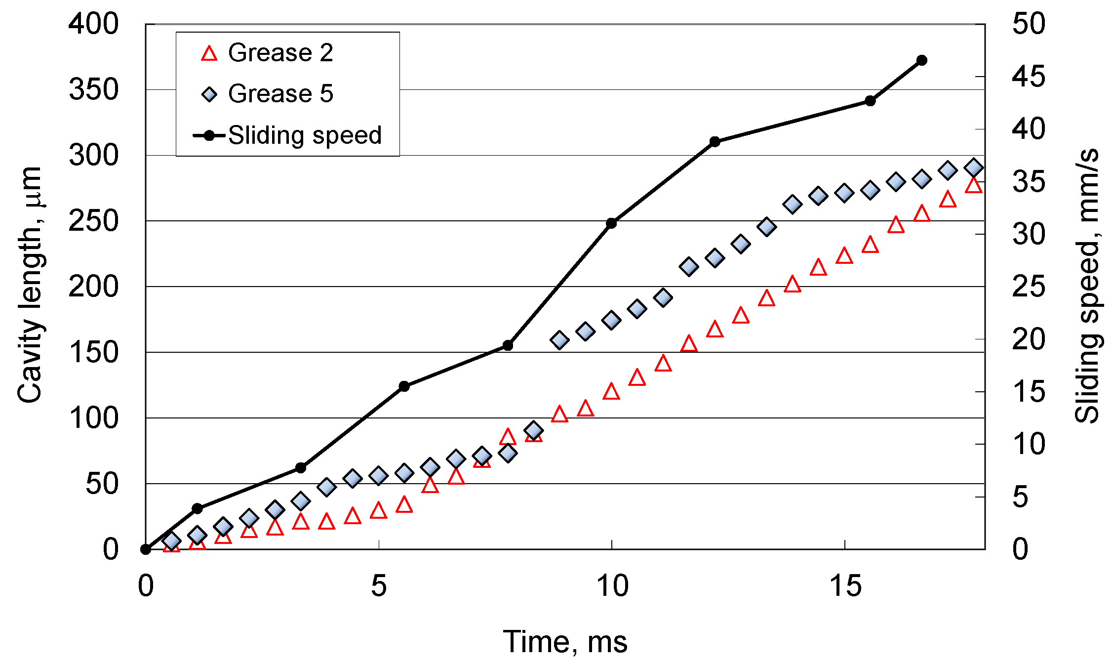
Lithium hydroxystearate grease (Grease 2) and diurea grease (Grease 5) have been selected to study the effect of the thickener. Cavity growth under the accelerating condition was observed in this study.
Figure 9 shows images of the cavity for the two greases. As it can be seen in these images, the cavity length changes from the start of the motion for both greases, but the shape of the cavitation region is different. For the lithium hydroxylstearate grease, the cavity shape is similar to that found for the base oil. This is obvious when comparing with the image taken at 7 ms shown in Figure 3. In both cases, a number of petal-like projections appear at the trailing edge of the cavity. On the other hand, a number of cavities are formed by lumps of thickener soon after the start of motion for the diurea grease. It can be seen that pocket cavities are formed not only at the edge of contact, but also at other positions in the outlet region of the contact. Each of these individual cavities grow with time. At 14 ms these cavities have merged to form a single, larger cavity. Figure 10 shows the change of the cavity length with time. The variation of the sliding speed in these tests is also shown in Figure 10. As it can be seen, the cavity length in diurea grease suddenly changes at 9 ms due to the merger of smaller cavities.
These results show that dispersion of the thickener in grease affects the formation of cavity. Negative pressure is generated behind the thickener lumps, resulting in small cavities formed partially at the outlet of contact. These small cavities may grow to a larger final cavity in some cases.

4. Cavity Growth Model in Grease Lubricated Contact

4.1. Two Stage of Cavity Growth

Figure 11 shows a schematic of the two-stage cavity growth revealed in this study. The results in Section 3.1 show that initial growth is faster than the growth in the second stage, and that duration of the initial stage in the grease is longer than that in the base oil. The time of initial growth is longer for the grease with the higher base oil viscosity, as shown in Section 3.2.
A similar trend of cavity growth was found for oil lubricants [32,35]. Otsu et al. [32] reported that, in the initial stage, cavity growth was related with the steep pressure drop at the exit of the EHD contact; dissolved gas was released rapidly because the pressure at outlet of contact drops to the saturation pressure of the gas. They also explained the mechanism in the initial stage by using a simple theoretical model. In the second stage, the cavity growth was caused mainly by the dissolved gas which was transferred to the cavity at the cavity–lubricant boundary by the difference in concentration, thus the cavity length increased gradually over time. These findings suggest that, in the grease lubricated contact, the viscosity of grease and the amount of dissolved gas in the grease are the cause of the difference in the cavity growth between the grease and the base oil.
In the initial stage, the negative pressure distribution at the exit of the contact depends on the viscosity of the lubricant if the sliding speed and the shape of the gap are the same. As the viscosity of greases depend on the shear rate, which should be greater than that of the oil, the pressure distribution should be different from that of the base oil. For greases with higher viscosity, the time of the initial stage of cavity growth should be longer because the pressure drop at the exit of contact is larger. Therefore, it would be worth extending the previous theoretical model to grease lubricated contacts by introducing the rheological properties of greases to see if these assumptions are correct. In addition, in case of diurea greases cavities are formed behind the thickener lumps, as shown in Section 3.3. This reveals that, in the initial stage, the negative pressure distribution partially changes due to thickener lumps passing through the contact.
In the second stage, our previous study [35] showed that the cavity growth in greases was different for different surrounding gas and the length increased with increasing gas solubility in the base oil. This implies that the cavity growth in greases occurred by the release of dissolved gas into cavity just as in the oil lubricated contact. In the present study, the experiments shown in Section 3.1 demonstrate that the cavity growth in the second stage is larger than that for the base oil. This suggests that the amount of dissolved gas in the grease is higher than that in the base oil. Another possible mechanism for the larger cavity in the second stage in greases may be related to the replenishment capability of grease into the cavity region. These two points will be addressed in future work.

4.2. Simple Numerical Analysis for Initial Stage of Cavity Growth

In order to understand the cavity growth in the initial stage, the simple theoretical analysis [32] is extended here to grease lubricated contacts. In this analysis, a parametric study with model greases is made in order to qualitatively understand the cavity growth with Grease 1 and its base oil, shown in Section 3.1. Pressure distribution in the divergent region of the conjunction is calculated by considering the viscosity of greases, and the relation between the negative pressure and cavity growth is discussed.
The shear dependence of the viscosity of greases is described here by the following simple equation:
  η = C 1 + C 2 γ ˙ m 1  
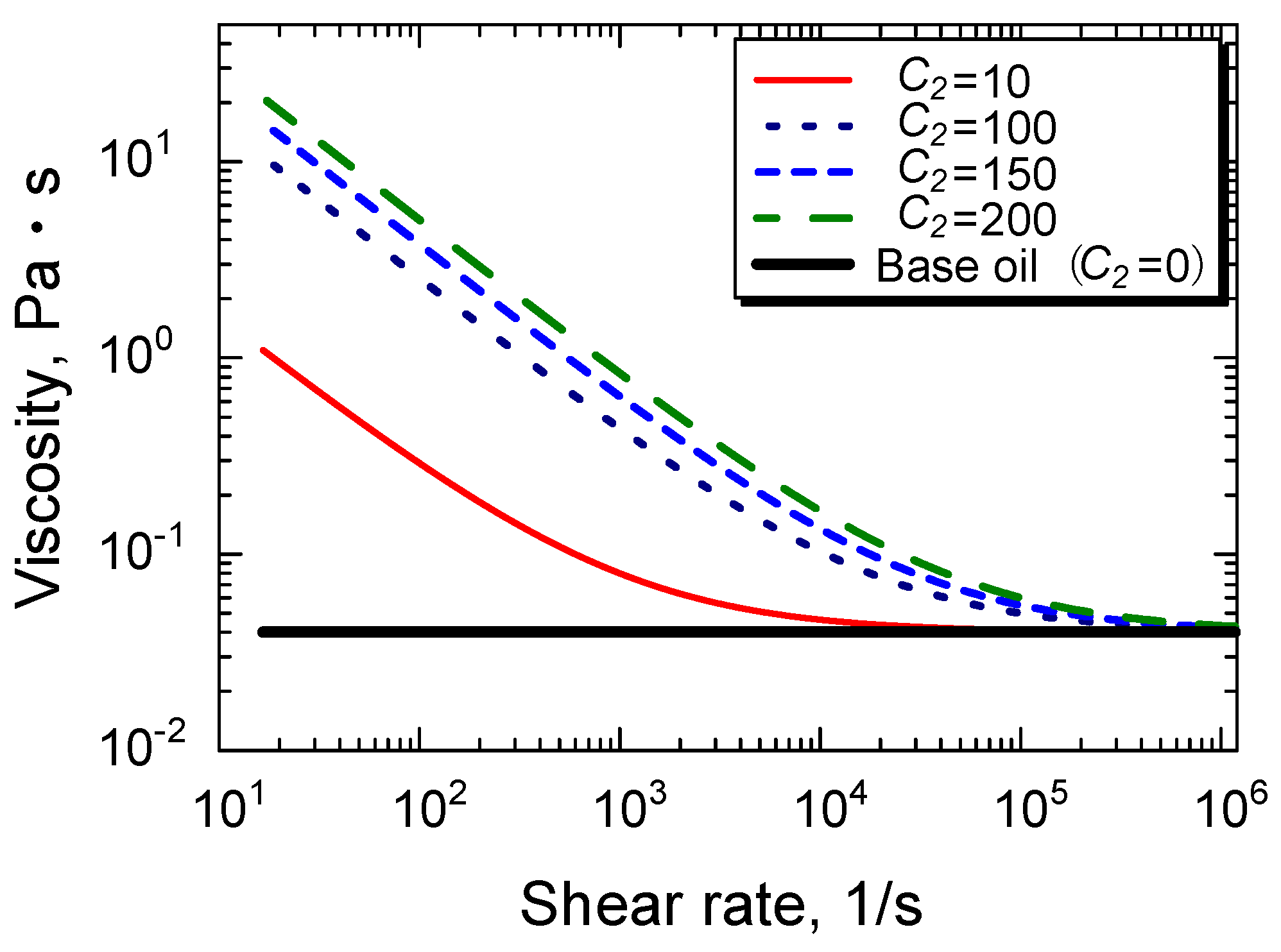
where η is viscosity, γ ˙ is the shear rate, C1, C2, and m are constants which determine the rheological behavior of the fluid. In the case where C1 and C2 are not zero and m is equal to zero, Equation (1) corresponds to a Bingham plastic material. According to Sakurai and coworkers [38], greases typically have C1 equal to base oil viscosity and m = 0.2, while m = 0.5 for a softened grease. For oils, C2 is zero, thus it is assumed that their viscosity does not depend on the shear rate. In this analysis, 0.04 Pa·s is used for C1 for the viscosity of the base oil of Grease 1 at 295 K. The viscosity of base oil was measured using a rotating cylinder viscometer. In addition, five values of C2, that is 0, 10, 100, 150, and 200, are chosen. Index m was taken as 0.2, as suggested by Sakurai, thus the viscosity of grease used in the test shown in Section 3.1, is given by:
  η = C 1 + C 2 γ ˙ m 1 = 0.04 + C 2 γ ˙ 0.8
Figure 12 illustrates the relationship between the viscosity and the shear rate given by Equation (2). The viscosity of the grease decreases with the shear rate, and the value reaches the base oil viscosity at high shear rate, of about at 106 s−1, which corresponds to the value in the lubrication film shown in the results in Section 3.1.
The pressure distribution at the outlet of the cavity region is evaluated by numerical calculation of the pressure given by Equation (3). Details of the derivation of this relationship are shown in the Appendix A.
  p = 6 C 1 U ( x 1 x 1 h 2 d x h m x 1 x 1 h 3 d x ) + 6 C 2 U 1 + n ( x 1 x 1 h 2 + n d x h m x 1 x 1 h 3 + n d x )
In this equation, h is the separation between the solid surfaces, hm is the separation corresponding to the local extreme value of the pressure, and n has the value −0.8.
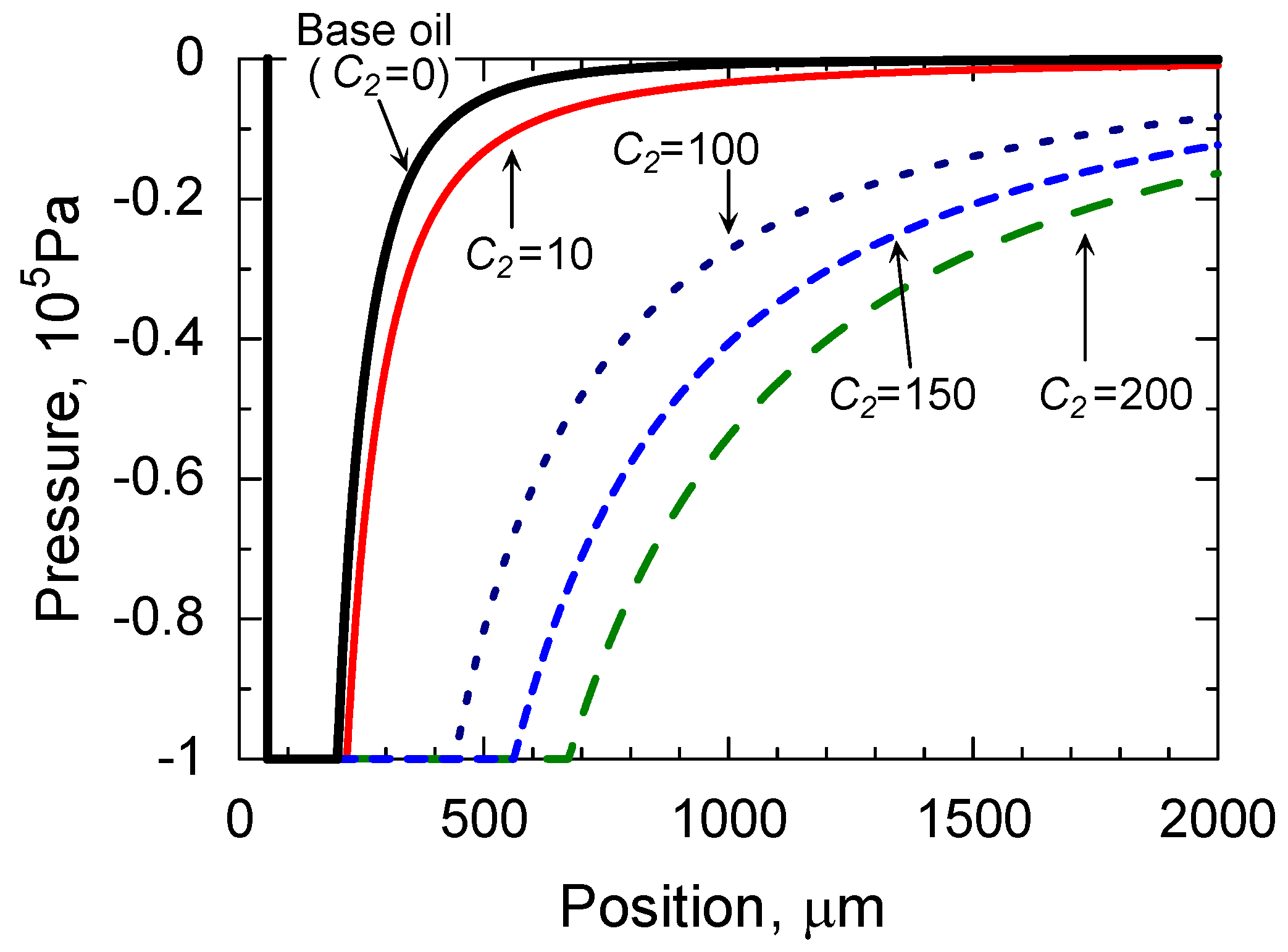
Figure 13 shows the pressure distribution at zero second for the base oil and three model greases with different C2. It clearly demonstrates that the region of absolute zero pressure, −0.1 MPa, is larger for the grease with higher C2. This is caused by higher viscosity.
Otsu et al. [32,35] reported that the cavity length after the initial growth is close to the length of −0.1 MPa negative pressure region at zero second. This means that C2 can be predicted by comparing the cavity length in the test and the calculated length of the negative pressure region. Figure 13 shows that the length of the −0.1 MPa region for C2 of 150 is about 500 μm, and this value is close to the cavity length after the initial growth of 450–470 μm, as shown in Figure 5. Thus, 150 is assumed to correspond to the value of C2 for Grease 1.
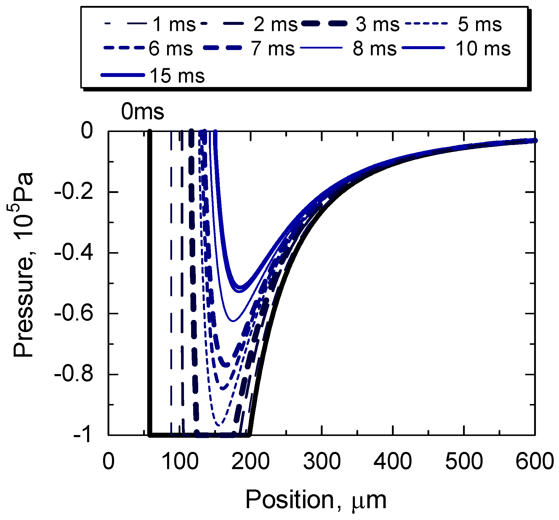
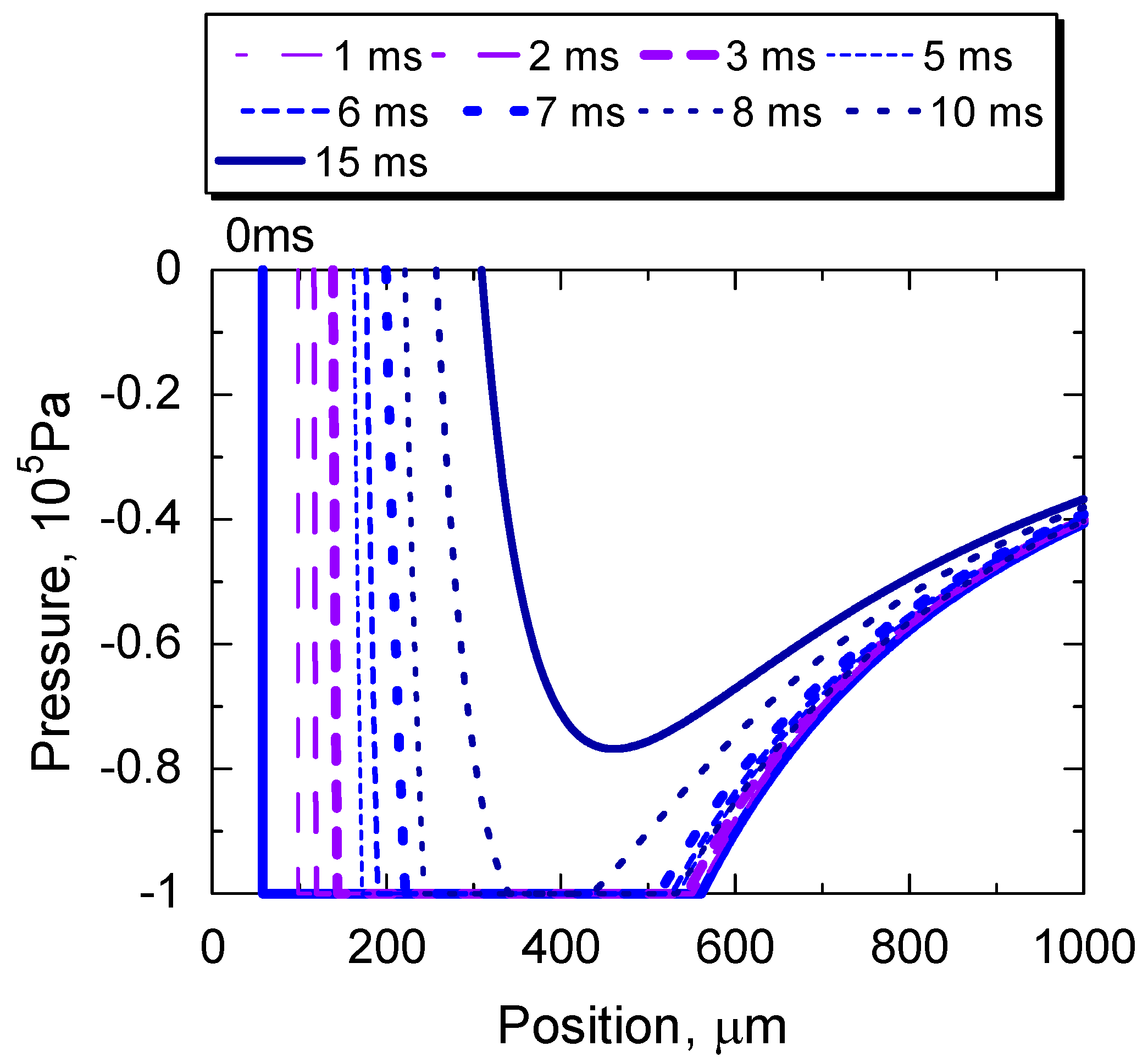
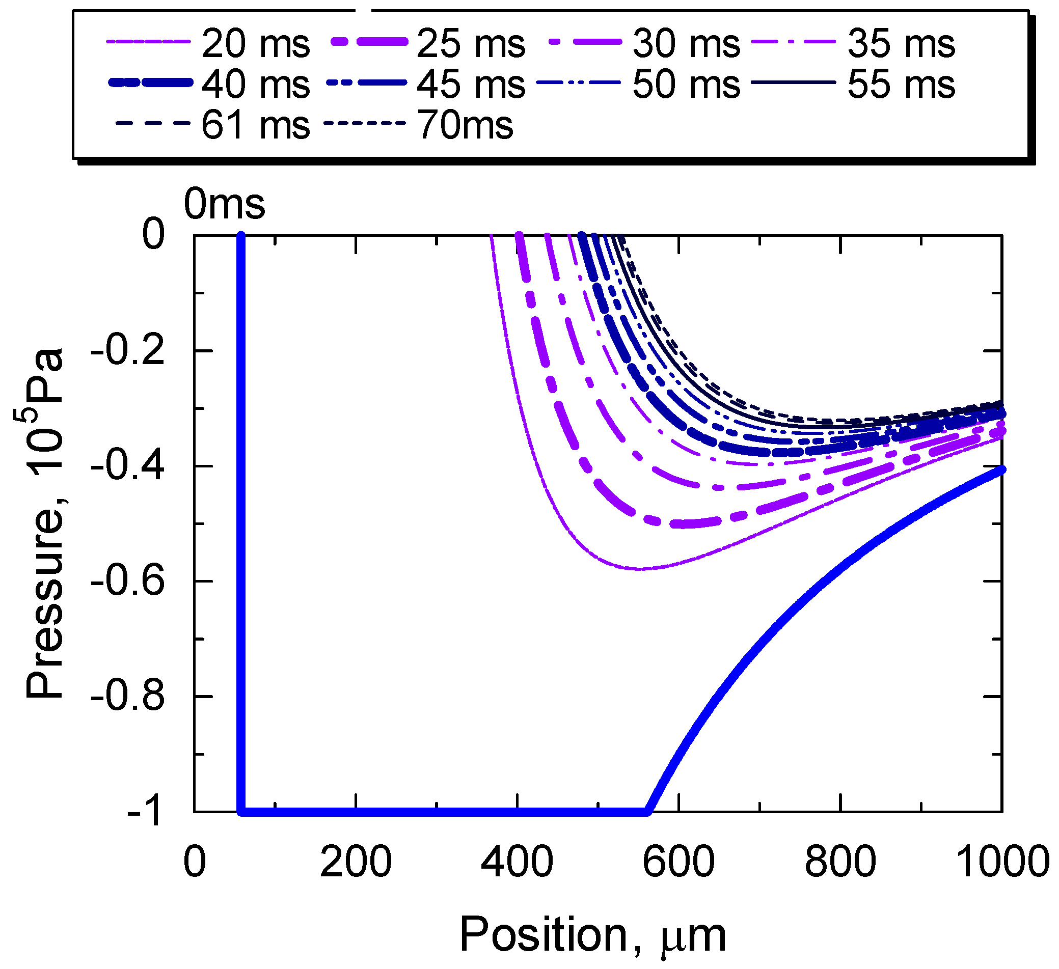
Figure 14, Figure 15 and Figure 16 show the variation with time of the calculated pressure distribution for the base oil and for the grease with C2 = 150, respectively. The viscosity of the oil, sliding speed, and film shape are the same with the values in the experiments, while the film thickness measured by the optical interferometry is used as hmin.
In the pressure distribution, the −0.1 MPa region at zero s governs the initiation of the cavity. Figure 14 and Figure 15 clearly demonstrate that the length of the −0.1 MPa region is larger in the grease than in the base oil. Also, the region of −0.1 MPa extends until 10 ms after the start for the grease and only until 3 ms for the oil, which is similar with the time for the rapid cavity growth shown in the experiments in Section 3.1. These figures also demonstrate that the pressure increases with time as the cavity grows with time, and that the pressure distribution in the grease and the oil does not substantially change after 55 and 10 ms, respectively.
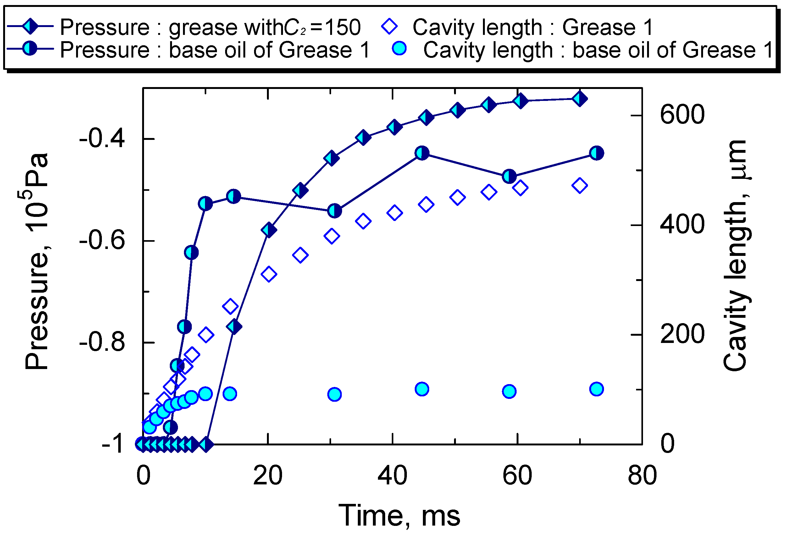
Figure 17 shows the changes in the maximum negative pressure and the cavity length with time for the base oil and the grease. In this figure, changes of the cavity length are for the test results of Grease 1 and the base oil in Section 3.1. All these figures demonstrate that rapid cavity growth occurs when pressure drop is steeper and this happens for both the grease and oil. The cavity growth time in the initial stage for the grease is longer because the steep pressure drop continues longer than for the oil. This suggests that the difference in the cavity growth is caused by different rheological properties. The shear rate dependence of the viscosity works to cause different growth behaviors.

5. Conclusions

Cavitation in grease-lubricated EHD contacts has been studied with the optical interferometry technique. The following conclusions are drawn from this study.
(1) Two stage cavity growths were observed in grease films, which is similar to those in the base oil. The cavity growth rate in the initial stage is higher than that in the second stage, and the growth time of the initial stage for the grease is longer than that for the base oil.
(2) The cavity length for greases is almost the same as that for their base oil up to 3 ms after the start of sliding, but is longer than that in the base oil after 3 ms under the present test conditions.
(3) The growth time of the initial stage is longer for higher base oil viscosity. After the growth in the initial stage, the cavity length for greases with higher base oil viscosity is longer.
(4) In diurea grease, lumps of thickener cause the formation of smaller, individual cavities immediately after the start.
(5) A theoretical analysis with a simple rheological model shows that the negative pressure (below ambient) region in grease lubricated contacts is greater than that for the base oil, which qualitatively agrees with the experimental results. The analysis suggests that the cavity growth in the initial stage is related to steep pressure drop and its relaxation.

Author Contributions

Conceptualization and Methodology, T.O., R.G., J.S.; Experiments and Calculations, T.O.; Data analysis and Discussion of results, T.O., R.G., J.S.; Draft writing and Review, T.O., R.G., J.S.

Funding

This research received no external funding.

Acknowledgments

The authors express their gratitude to NSK Ltd. for supplying the greases.

Conflicts of Interest

The authors declare no conflict of interest.

Appendix A

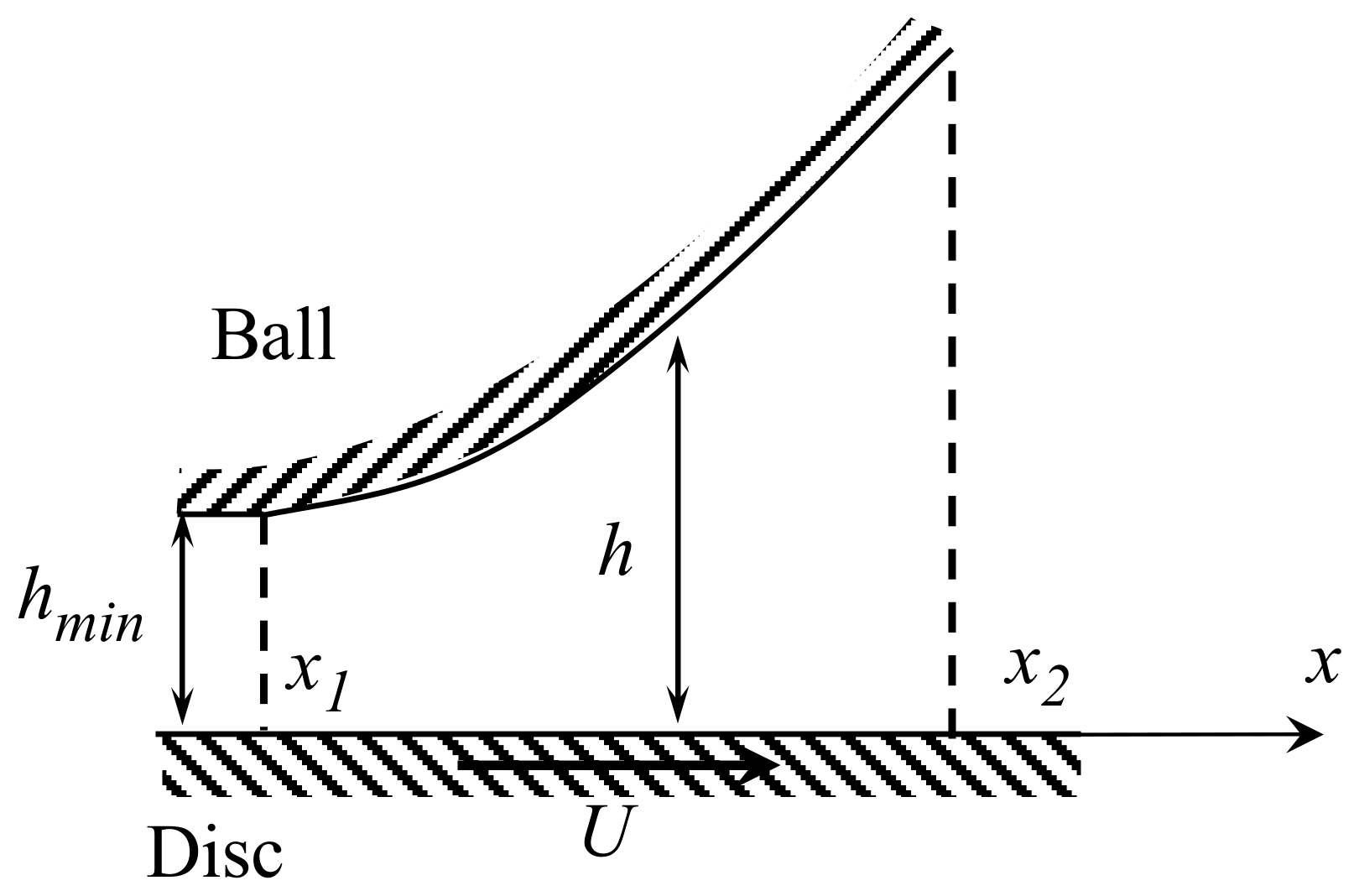
Consider the geometry downstream of the contact between the ball and the disc at the exit region, beyond the exit constriction, as illustrated in Figure A1 [32].
Figure A1. Geometry of the exit region of contact.
Lubricants 06 00075 g0a1
The separation between the surfaces h can be expressed by the relationship [39]:
  h = h m i n + a 2 π R [ ( 2 x 2 a 2 ) cos 1 a x + ( x 2 a 2 1 ) 0.5 ]
where a is the radius of the contact area and R is the reduced radius of curvature of the surfaces.
It is obvious that the shear rate, defined as γ ˙ = U / h is not constant in this region, and according to Equation (A1) the viscosity of the lubricant is assumed to vary with the position from the contact.
  η = C 1 + C 2 ( U h ) n
The 2-D Reynolds equation is as follows:
  d p d x = 6 η U h h m h 3
where η is a function of h and implicitly of x.
By substituting (A1) and (A2) in (A3), separating the variables and integrating yield the following expression for the pressure.
  p = 6 C 1 U ( x 1 x 1 h 2 d x h m x 1 x 1 h 3 d x ) + 6 C 2 U 1 + n ( x 1 x 1 h 2 + n d x h m x 1 x 1 h 3 + n d x ) + C 3
where C3 is a constant of integration. x1 is a + lc, where a is the radius of the Hertzian contact area and lc is cavity length, if the axis x is taken from the center of the Hertzian contact, x2 is the position of the end of fully flood zone [32].
As boundary conditions, the pressure at x1 and x2 is assumed to be zero. C3 and hm can be obtained as follows:
C3 = 0
  h m = C 1 x 1 x 2 1 h ( x ) 2 d x + C 2 U n x 1 x 2 1 h ( x ) 2 + n d x C 1 x 1 x 2 1 h ( x ) 3 d x + C 2 U n x 1 x 2 1 h ( x ) 3 + n d x
It follows that the pressure distribution is described by the following Equation (A7).
  p = 6 C 1 U ( x 1 x 1 h 2 d x h m x 1 x 1 h 3 d x ) + 6 C 2 U 1 + n ( x 1 x 1 h 2 + n d x h m x 1 x 1 h 3 + n d x )

References

  1. Dowson, D.; Godet, M.; Tayler, C.M. Cavitation and Realated Phenomena in Lubrication; Mechanical Engineering Publications Ltd.: Bury St Edmunds, UK, 1975. [Google Scholar]
  2. Sakai, F.; Ochiai, M.; Hashimoto, H. CFD Analysis of Journal Bearing with Oil Supply Groove Considering Two-Phase Flow. In Proceedings of the 4th International Conference on Design Engineering and Science, ICDES 2017, Aachen, Germany, 17–19 September 2017; p. 131. [Google Scholar]
  3. Otsu, T.; Nishida, K. Growth of Cavitation in Journal Bearing and Effect of Cavitation on Behavior of Bearing. J. Jpn. Soc. Tribol. 2016, 61, 127–136. (In Japanese) [Google Scholar]
  4. Tokunaga, Y.; Sugimura, J.; Yamamoto, Y. Development and Performance Verification in Mechanical Seals with Friction Reduction and Sealing Mechanism-Experimental Study. J. Jpn. Soc. Tribol. 2015, 60, 332–341. (In Japanese) [Google Scholar]
  5. Vasilakos, I. Cavitation in the Cylider-Liner and Piston-Ring Interaction in Internal Combustion Engines. Ph.D. Thesis, University of London, London, UK, 2017. [Google Scholar]
  6. Tang, T.; Morris, N.; Coupland, J.; Arevalo, L. Cavitation Bubble Measurement in Tribological Contacts Using Digital Holographic Microscopy. Tribol. Lett. 2015, 58, 1–10. [Google Scholar] [CrossRef] [Green Version]
  7. Shen, C.; Khonsari, M.M. On the Magnitude of Cavitation Pressure of Steady-State Lubrication. Tribol. Lett. 2013, 51, 153–160. [Google Scholar] [CrossRef]
  8. Yagi, K.; Sato, H.; Sugimura, J. On the Magnitude of Load-Carrying Capacity of Textured Surfaces in Hydrodynamic Lubrication. Tribol. Online 2015, 10, 232–245. [Google Scholar] [CrossRef] [Green Version]
  9. Nishikawa, H.; Handa, K.; Kaneta, M. Behaviour of EHL Films in Reciprocated Motion. JSME Int. J. 1995, 38, 558–567. [Google Scholar]
  10. Pemberton, J.; Cameron, A.A. A Mechanism of Fluid Replenishment in Elstohydrodynamic Contacts. Wear 1976, 37, 185–190. [Google Scholar] [CrossRef]
  11. Jackson, A.; Cameron, A. An Interferometric Study of the EHL of Rough Surfaces. ASLE Trans. 1976, 19, 50–60. [Google Scholar] [CrossRef]
  12. Cann, P.M.E. Thin-film Grease Lubrication. Proc. Inst. Mech. Eng. 1999, 213, 405–416. [Google Scholar] [CrossRef]
  13. Leonard, B.; Sadeghi, F.; Cipra, R. Gaseous Cavitation and Wear in Lubricated Fretting Contacts. Tribol. Trans. 2008, 51, 351–360. [Google Scholar] [CrossRef]
  14. Etsion, I.; Halperin, G.; Brizmer, V.; Kligerman, Y. Experimental Investigation of Laser Surface Textured Parallel Thrust Bearings. Tribol. Lett. 2004, 17, 295–300. [Google Scholar] [CrossRef]
  15. Ryk, G.; Kligerman, Y.; Etsion, I.; Shinkarenko, A. Experimental Investigation of Partial Laser Surface Texturing for Piston-ring Friction Reduction. Tribol. Trans. 2005, 48, 583–588. [Google Scholar] [CrossRef]
  16. Yagi, K.; Takedomi, W.; Tanaka, H.; Sugimura, J. Improvement of Lubrication Performance by Micro Pit Surfaces. Tribol. Online 2008, 3, 285–288. [Google Scholar] [CrossRef]
  17. Sato, Y.; Seki, K.; Sugimura, J.; Yamamoto, Y. Experiments and Simple Modelling of Hydrodynamic Lubrication in Radial Shaft Seals. In Proceedings of the 17th International Conference of Fluid Sealing, York, UK, 8–10 April 2003; BHR Group: Cranfield, UK, 2003; pp. 139–156. [Google Scholar]
  18. Nau, B.S. Film Cavitation Observation in Face Seals. In Proceedings of the 4th International Conference on Fluid Sealing, Philadelphia, PA, USA, 5–8 May 1969; BHRA: Cranfield, UK, 1969; pp. 190–198. [Google Scholar]
  19. Anno, J.N.; Walowit, J.A. Microasperity Lubrication. J. Lubr. Technol. 1968, 90, 351–355. [Google Scholar] [CrossRef]
  20. Sisko, A.W. The flow of lubricating greases. Ind. Eng. Chem. 1958, 50, 1789–1792. [Google Scholar] [CrossRef]
  21. Dyson, A.; Wilson, A.R. Film Thickness in Elastohydrodynamic Lubrication of Rollers by Greases. Proc. Inst. Mech. Eng. 1970, 184, 1–11. [Google Scholar]
  22. Kaneta, M.; Ogata, T.; Takubo, Y.; Naka, M. Effects of a Thickener Structure on Grease Elastohydrodynamic Lubrication Films. Proc. Inst. Mech. Eng. 2000, 214, 327–336. [Google Scholar] [CrossRef]
  23. Couronné, I.; Mazuyer, D.; Vergne, P.; Truong-Dinh, N.; Girodin, D. Effects of Grease Composition and Structure on Film Thickness in Rolling Contact. Tribol. Trans. 2003, 46, 31–36. [Google Scholar] [CrossRef]
  24. Eriksson, P.; Wikstroèm, V.; Larsson, R. Grease Passing Through an Elastohydrodynamic Contact under Pure Rolling Conditions. Proc. Inst. Mech. Eng. 2000, 214, 309–316. [Google Scholar] [CrossRef]
  25. Kauzlarich, J.; Greenwood, J.A. Elastohydrodynamic Lubrication with Herschel-Bulckley Model Greases. ASLE Trans. 1972, 15, 269–277. [Google Scholar] [CrossRef]
  26. Yanggang, M.; Jie, Z. A Rheological Model for Lithium Lubricating Grease. Tribol. Int. 1998, 31, 619–625. [Google Scholar] [CrossRef]
  27. Cann, P.M.E. Starved Grease Lubrication of Rolling Contacts. Tribol. Trans. 1999, 42, 867–873. [Google Scholar] [CrossRef]
  28. Hurley, S.; Cann, P.M.; Spikes, H.A. Lubrication and Reflow Properties of Thermally Aged Greases. Tribol. Trans. 2000, 43, 221–228. [Google Scholar] [CrossRef]
  29. Dowson, D. Investigation of Cavitation in Lubricating Films Supporting Small Loads. In Proceedings of the Conference on Lubrication and Wear, London, UK, 1–3 October 1957; pp. 93–99. [Google Scholar]
  30. Archard, J.F.; Kirk, M.T. Influence of Elastic Modulus on the Lubrication of Point Contacts. Lubr. Wear Conv. 1963, 15, 181–189. [Google Scholar]
  31. Otsu, T.; Tanaka, H.; Izumi, N.; Sugimura, J. Effect of Surrounding Gas on Cavitation in EHL. Tribol. Online 2009, 4, 50–54. [Google Scholar] [CrossRef]
  32. Otsu, T.; Tanaka, H.; Sugimura, J. Initiation and Growth of Gaseous Cavity in Concentrated Contact in Various Surrounding Gas. Tribol. Int. 2012, 53, 68–75. [Google Scholar] [CrossRef]
  33. Otsu, T.; Tanaka, H.; Sugimura, J. Effect of Temperature on Growth of Gaseous Cavitation in Point Contact EHL. J. Jpn. Soc. Tribol. 2014, 59, 648–656. (In Japanese) [Google Scholar]
  34. Otsu, T.; Tanaka, H.; Sugimura, J. Effect of Surrounding Pressure on Cavity Growth in EHD contact. In Proceedings of the International Tribology Conference Hiroshima, Hiroshima, Japan, 30 October–3 November 2011; p. E4-07. [Google Scholar]
  35. Otsu, T. Study on Cavitation in Elastohydrodynamic Lubrication. Ph.D. Thesis, Kyushu University, Fukuoka, Japan, 2012. (In Japanese). [Google Scholar]
  36. Cann, P.M.; Hutchinson, J.; Spikes, H.A. The Development of a Spacer Layer Imaging Method (SLIM) for Mapping Elastohydrodynamic Contacts. Tribol. Trans. 1996, 39, 915–921. [Google Scholar] [CrossRef]
  37. Stadler, K.; Izumi, N.; Morita, T.; Sugimura, J.; Piccigallo, B. Estimation of Cavity Length in EHL Rolling Point Contact. ASME Trans. J. Tribol. 2008, 130. [Google Scholar] [CrossRef]
  38. Sakurai, T.; Hoshino, M.; Tokashiki, M.; Fujita, M. Grease for Lubrication and Synthetic Lubricant; Saiwai-Syobou: Tokyo, Japan, 1983; p. 80. (In Japanese) [Google Scholar]
  39. Wedeven, L.D.; Evens, D.; Cameron, A. Optical analysis of ball bearing starvation. Trans. ASME J. Lubr. Technol. 1971, 93, 349–363. [Google Scholar] [CrossRef]
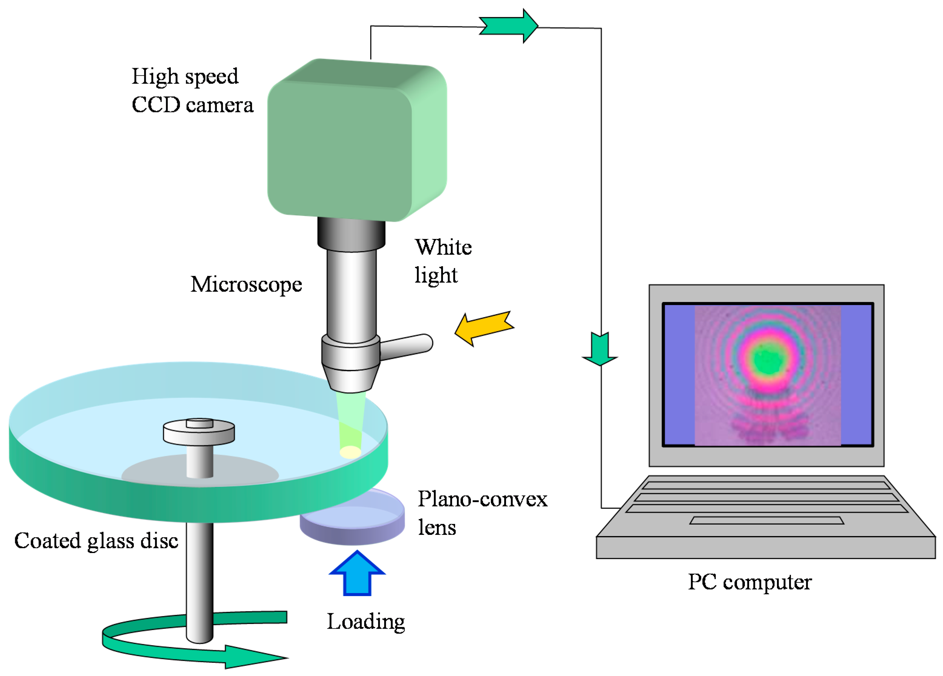
Figure 1. Experimental set up.
Lubricants 06 00075 g001
Figure 2. Definition of cavity length.
Lubricants 06 00075 g002
Figure 3. Photographs of cavity in Grease 1 until 60 ms after the start.
Lubricants 06 00075 g003aLubricants 06 00075 g003b
Figure 4. Photographs of cavity in base oil of Grease 1 until 16 ms after the start.
Lubricants 06 00075 g004
Figure 5. Changes in cavity length from the start to 80 ms for Grease 1 and its base oil.
Lubricants 06 00075 g005
Figure 6. Photographs of the cavity in Grease 1 and its base oil at 0.1, 0.5, and 1 s.
Lubricants 06 00075 g006
Figure 7. Changes in cavity length from the start to 1 s for Grease 1 and its base oil.
Lubricants 06 00075 g007
Figure 8. Effect of base oil viscosity on cavity growth for Grease 2, 3, and 4.
Lubricants 06 00075 g008
Figure 9. Cavity growth in Grease 2 and Grease 5.
Lubricants 06 00075 g009
Figure 10. Changes in cavity length during acceleration regime for Grease 2 and Grease 5.
Lubricants 06 00075 g010
Figure 11. Cavity growth in two stages.
Lubricants 06 00075 g011
Figure 12. Relationship between viscosity and shear rate.
Lubricants 06 00075 g012
Figure 13. Effect of C2 on negative pressure distribution.
Lubricants 06 00075 g013
Figure 14. Changes in pressure distribution with time in base oil of Grease 1.
Lubricants 06 00075 g014
Figure 15. Changes in pressure distribution with time in grease with C2 = 150.
Lubricants 06 00075 g015
Figure 16. Changes in pressure distribution until 70 ms in grease with C2 = 150.
Lubricants 06 00075 g016
Figure 17. Relation between minimum pressure and cavity growth for the grease and its base oil.
Lubricants 06 00075 g017
Table 1. Properties of greases.
No.ThickenerBase Oil Viscosity @313, 373 KWorked Penetration (Consistency)
Grease 1Lithium stearate, 12 mass%19, 4.1 [mm2/s]336
Grease 2Lithium hydroxystearate, 12 mass%31, 5.8 [mm2/s]236
Grease 3Lithium hydroxystearate, 12 mass%66, 10 [mm2/s]291
Grease 4Lithium hydroxystearate, 12 mass%411, 41 [mm2/s]386
Grease 5Diurea, 13.4 mass%31, 5.8 [mm2/s]280