Article

Simulation Analysis and Structural Improvements of Oil Return in Main Bearing Chamber of Aero-Engine

1
Research Institute of Aero-Engine, Beihang University, Beijing 102206, China
2
AECC Shenyang Engine Research Institute, Shenyang 110163, China
3
AECC Key Laboratory of Power Transmission Technology on Aero-Engine, Shenyang 110015, China
4
School of Energy and Power Engineering, Beihang University, Beijing 102206, China
*
Author to whom correspondence should be addressed.
Lubricants 2025, 13(9), 381; https://doi.org/10.3390/lubricants13090381
Submission received: 19 June 2025 / Revised: 15 August 2025 / Accepted: 22 August 2025 / Published: 26 August 2025

Abstract

Modern advanced aero-engine bearing systems typically exhibit structural and loading characteristics with high DN values. The harsh thermal environment and multi-physics loads under operating conditions render the reliability of bearing structural systems particularly sensitive to lubrication efficiency and bearing chamber temperature. This study performs simulation analyses of oil return processes and their influencing factors in an aero-engine main bearing chamber with complex structural features. The results show two primary causes of reduced scavenging performance. On the one hand, the local low-speed region at the inlet of the scavenge pipe causes some oil to fail to enter the scavenge pipe normally. On the other hand, the air in the bearing chamber is disturbed by the rotation of the rotor, which makes oil enter the oil sump with a tendency to return to the oil collection annulus, thereby causing poor oil return. Furthermore, two structural improvements of the oil sump are proposed. These improvements avoid the disruptive effects of circumferential fluid motion in the oil collection annulus on the pressure and velocity distribution within the bearing chamber, thereby improving scavenging performance.

1. Introduction

With increasing demands for lightweight and high efficiency advanced aero-engines, bearing-supporting structural systems typically exhibit high DN values while being subjected to significant dynamic fulcrum loads and harsh thermal environments [1,2]. Concurrently, progressive miniaturization of bearing chamber geometries imposes critical challenges on the design of lubrication and cooling systems. In particular, a reasonable oil sump design is critical for ensuring rapid lubricant recovery post-cooling operations, minimizing oil residence time within the chamber, and serving as a prerequisite for enhancing lubrication efficiency and mitigating leakage risks [3].
Substantial research efforts have been devoted to characterizing oil–air two-phase flow and oil return processes within the bearing chambers of aero-engines. To accurately predict the motion of an oil–air mixture under operational conditions, significant efforts have been invested in developing advanced two-phase flow simulation techniques. For two-phase interface capturing in bearing chambers, the Volume-of-Fluid (VOF) method [4] and the Level-Set method [5] remain widely adopted due to their robustness in handling complex topological changes. As a complement to interface-capturing approaches, thin-film modeling treats the wall-bounded liquid as a shallow layer and solves depth-averaged mass-momentum equations derived from lubrication theory [6]. In bearing chambers, Farrall et al. formulated a chamber-specific thin-film model that couples interfacial shear, wall friction, gravity, and centrifugal forces, and includes source/sink terms for impingement and entrainment, matching rig data across conditions [7]. Building on this line of work, Wang et al. developed a numerically robust thin-film framework for bearing chambers, clarified the closure relations for interfacial shear and entrainment and their coupling to the gas-phase solution, and demonstrated predictive capability across a broader range of chamber geometries and speeds [8]. Both the Volume-of-Fluid (VOF) and Level-Set methods are Eulerian interface-capturing approaches for gas–liquid flows and are widely used to handle severe topological changes in bearing-chamber simulations [4,5]. In contrast, thin-film modeling treats the wall oil film as a shallow Eulerian layer governed by depth-averaged mass–momentum equations derived from lubrication theory [6], and has been further extended into numerically robust frameworks for aero-engine bearing chambers [8,9]. Complementarily, two-way-coupled Eulerian–Lagrangian droplet tracking has been applied to bearing-chamber geometries to resolve dispersed-phase transport and its feedback on the core flow [10]. Hybrid strategies that couple an Eulerian thin-film model with VOF in thicker-film regions have also been demonstrated to improve multi-scale predictive capability at a practical cost [11]. These advancements aim to enhance predictive capabilities for optimizing bearing chamber performance and reliability. Simmons et al. [10] used two-way coupling for droplet tracking with the standard k–ε turbulence model to assess interactions between air flow and droplets. They found that drag primarily increases local air velocity and that smaller droplets (<100 μm) are more susceptible to perturbations. This approach addresses the limitation of one-way coupling, which neglects mutual interaction, thereby improving predictions of airflow and impingement. Ren et al. [12] combined the Discrete Phase Model (DPM) with VOF to analyze transient film thickness and wall volume fraction under speed variations, and proposed two sump-design improvements to enhance scavenging performance. Li [13] used a mixture multiphase model and VOF to study flow-field distributions versus speed and phase interaction.
Accurate modeling of the gas-phase flow is essential in air–oil simulations. Understanding of the airflow and oil dynamics is critical for addressing momentum and energy transport phenomena between two phases during subsequent analyses. Lee et al. [14] employed Particle Image Velocimetry (PIV) to measure the gas-phase flow field in bearing chambers, revealing that spindle rotation and chamber geometry significantly influence the gas-phase flow characteristics. Chen et al. [15] utilized CFX software to numerically simulate the gas-phase flow field in aero-engine bearing chambers, analyzing the effects of structural features (e.g., exhaust port configurations), sealing gap sizes, and operational conditions on gas-phase flow behavior. Their findings demonstrated that chamber geometry parameters and working conditions distinctly alter the flow regimes. Lü et al. [16] proposed bidirectional coupling between air–oil two-phase flow and droplets, and showed reduced velocities and strong dependence of turbulence on oil motion and vaporization. Wang et al. [17] combined finite element numerical simulations with experimental validation to investigate pressure and velocity fields in gas-phase under varying operational conditions (e.g., rotational speed, seal air inflow rate). Results showed that wall surface air phase velocity and pressure increase proportionally with higher speed and seal air flow.
Based on the analysis of oil–air two-phase flow characteristics, targeted design optimizations were implemented for the oil return structures. These improvements effectively mitigate prolonged oil retention, enhance scavenging performance, and thereby extend engine service life while improving operational reliability. Yang [18] and Crouchez-Pillot et al. [19] used VOF-based CFD to show that sump-structure parameters significantly affect oil return and wall heat transfer. Chandra et al. [20,21,22,23,24] studied tangential and deep sump structures, and proposed a new off-take geometry that reduces oil residence time and leakage risk. Kurz et al. [25,26] used capacitive film-thickness measurements to compare a traditional design, a baffle-free shallow sump, and a baffled deep sump, showing the strong dependence of film thickness and scavenge efficiency on speed and flow rate.
Existing studies have established mechanistic models of the simulation analysis and structural optimization of oil flow characteristics but do not consider the complex structures of the actual bearing chambers. Therefore, this study investigates simulation analysis for the oil return process in a bearing chamber with complex structural features. Moreover, two improved structures are proposed to enhance the scavenging performance of the bearing chamber.

2. The Rear Bearing Chamber Structure System

2.1. Structural Characteristic

Figure 1 illustrates the schematic diagram of a specific turbofan engine. An intermediate bearing at the No. 4 support point, located between the high-pressure and low-pressure turbine rotors, operates under high loads. Since the No. 4 support point is relatively close to the rear support point of the low-pressure turbine rotor (No. 5 support point), they share a common oil supply–return system to reduce weight. The rear bearing chamber supplies cooling and lubrication for both supports.
Figure 2 illustrates the structural schematic of the rear bearing chamber. It comprises the rear journal of the high-pressure and low-pressure rotors, the turbine rear bearing frame, and the No. 4 and No. 5 bearings, along with their clamping components and sealing structures. The low-pressure rear journal divides the rear bearing chamber into two parts, the No. 4 and No. 5 bearing chambers, connected through vent holes in the journal. The oil sump sits at 6 o’clock in the No. 5 chamber and connects directly to the chamber.
The No. 5 bearing chamber is divided by the No. 5 bearing and the turbine rear bearing frame radial plates into two annulus chambers (shown as region I and II in Figure 2, referred to as the front oil collection annulus and the rear oil collection annulus). These two annuli are connected through eleven axial vent holes on the turbine rear bearing frame radial plates. Although the front and rear oil annuli are interconnected, their internal flow field states differ significantly. The front annulus has a large contact area with the low-pressure rotor rear journal, where the contact region exhibits high tangential velocity. Consequently, the airflow in this chamber demonstrates significant circumferential flow characteristics driven by the low-pressure rotor. In contrast, the rear annulus primarily interfaces with the rear baffle, with a relatively lower tangential velocity. Therefore, compared to the front annulus, the circumferential flow tendency in this annulus is less pronounced. In summary, the solid domain (composed of rotor, stator, and bearing components) and the fluid domain (composed of oil–gas multiphase fluid in the chamber) interact reciprocally, posing challenges for predicting oil flow states and analyzing structural damage in the bearing chamber.

2.2. Oil Flow Process

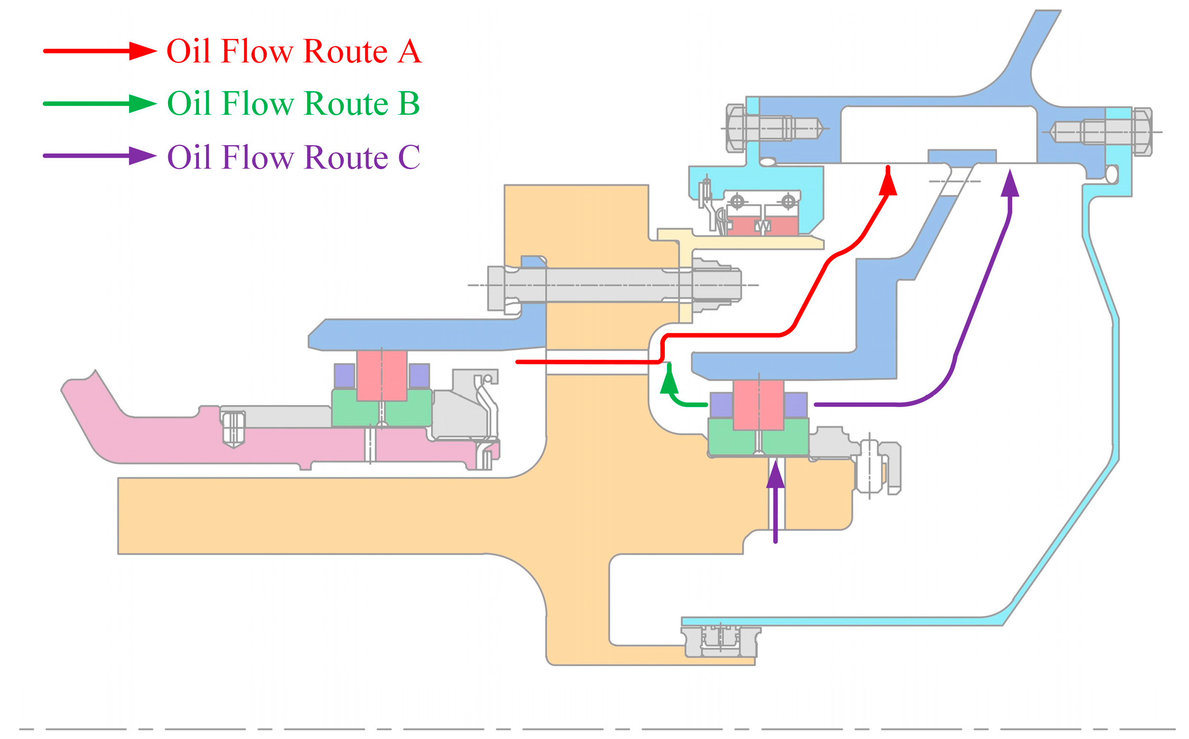
Figure 3 depicts the oil flow path. After cooling and lubricating the No. 4 bearing, the oil enters the No. 5 bearing chamber through vent holes in the low-pressure rotor rear journal (route A). A portion of the oil used for the No. 5 bearing is centrifugally ejected from the front side into the front annulus and then moves radially to the sump (route B). The rest exits the rear side, enters the rear annulus, and flows to the sump under centrifugal force (route C).
In the above oil flow process, the design in which the oil sump connects to the front annulus creates a problem. This configuration causes all oil to be affected by the high-speed circumferential flow in the front annulus as the oil enters the scavenge pipe, which adversely affects scavenging performance. Additionally, the scavenge pipe inlet is positioned at the edge of the oil sump, where disturbances from circumferentially moving air negatively impact the flow of oil at the inlet, further reducing scavenging performance. Consequently, a detailed analysis of the oil return process within the bearing chamber is necessitated.

3. Simulation Model of Oil Return Process

3.1. Geometric Model

The structure of the bearing chamber is shown in Figure 4. The specific structural dimension parameters are detailed in Table 1.

3.2. Mesh Division

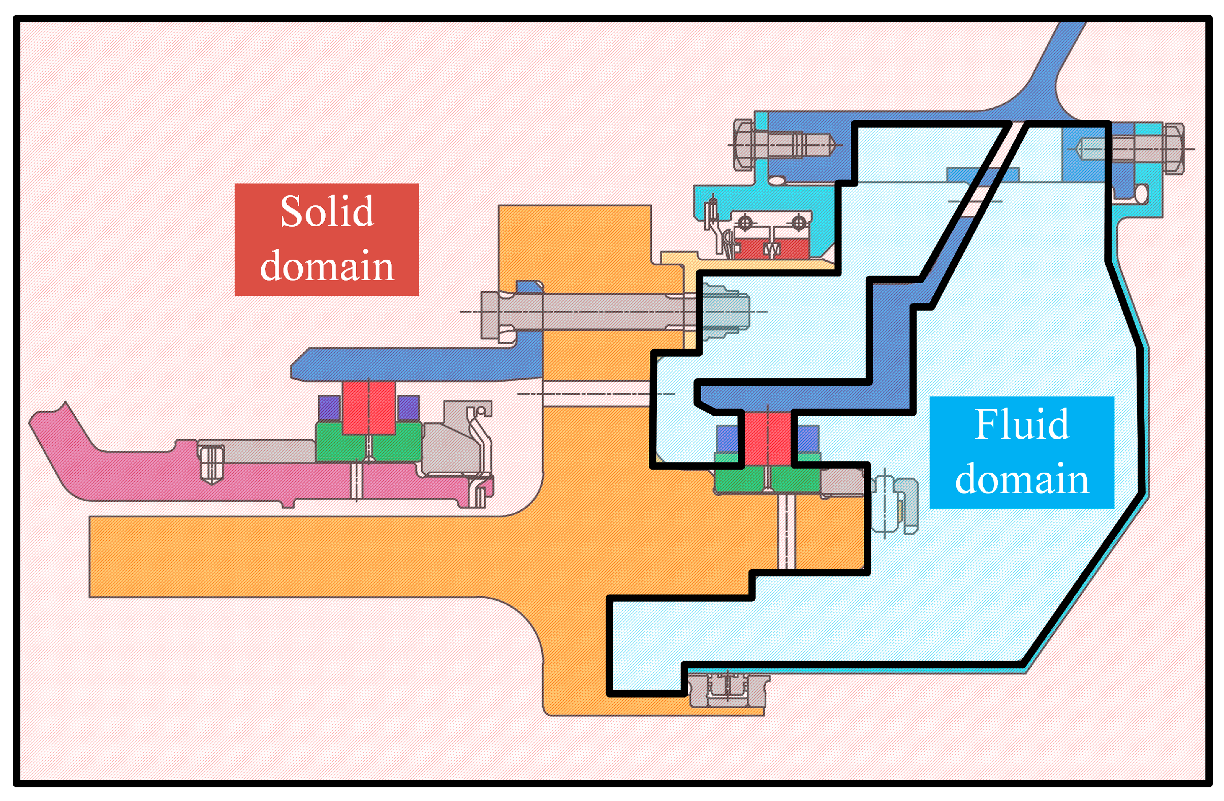
The oil sump connects only to the No. 5 bearing chamber. As previously explained, the oil return process primarily relates to the oil flow state in the No. 5 bearing chamber. Since the No. 4 bearing chamber connects to the No. 5 bearing chamber only through vent holes, the oil flow process in the No. 4 bearing chamber has a negligible influence on the oil return process. Therefore, the simulation model for the rear bearing chamber oil return process excludes the impact of the No. 4 bearing. Figure 5 shows the fluid domain and solid domain boundaries of the selected simulation model.
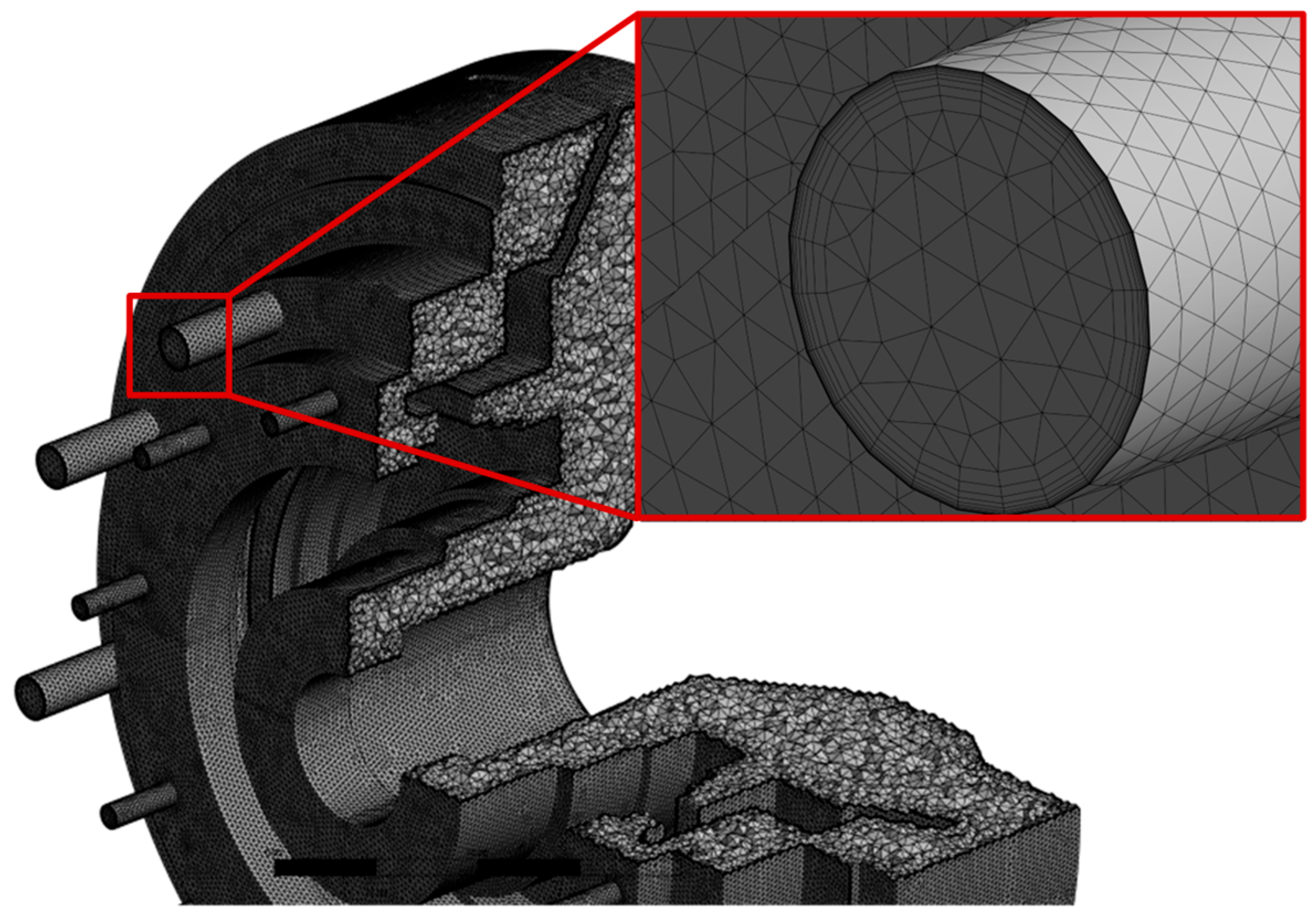
As shown in Figure 6, the grid division of the fluid domain of the rear bearing structural system is presented. To accurately capture the multiphase interactions between the oil–air mixture and solid boundaries, a boundary layer mesh refinement has been implemented.
To ensure simulation accuracy while minimizing computational effort, mesh independence verification is conducted by performing numerical calculations on bearing chamber models with mesh counts of 0.95 million, 1.22 million, 1.4 million, 1.79 million, and 2.17 million. The results are presented in Figure 7. The axial velocity distribution curves at a radial position of r = 150 mm from centerline of the oil return chamber revealed that the velocity gradually increased with mesh refinement until reaching 1.79 million, beyond which no significant variation is observed. Consequently, a mesh count of 1.79 million is selected to balance computational efficiency and solution accuracy.

3.3. Boundary Conditions

Two kinds of fluids, air and oil, are considered in the fluid domain. The properties of the fluids used in the simulation are shown in Table 2. To isolate the influence of geometric configuration and sealing flow conditions on the oil–air two-phase flow under typical high-altitude cruise conditions, the simulations are conducted with a stable rotational speed, sealing air flow rate, and bearing chamber temperature, taking 100 °C as the representative calculation temperature.
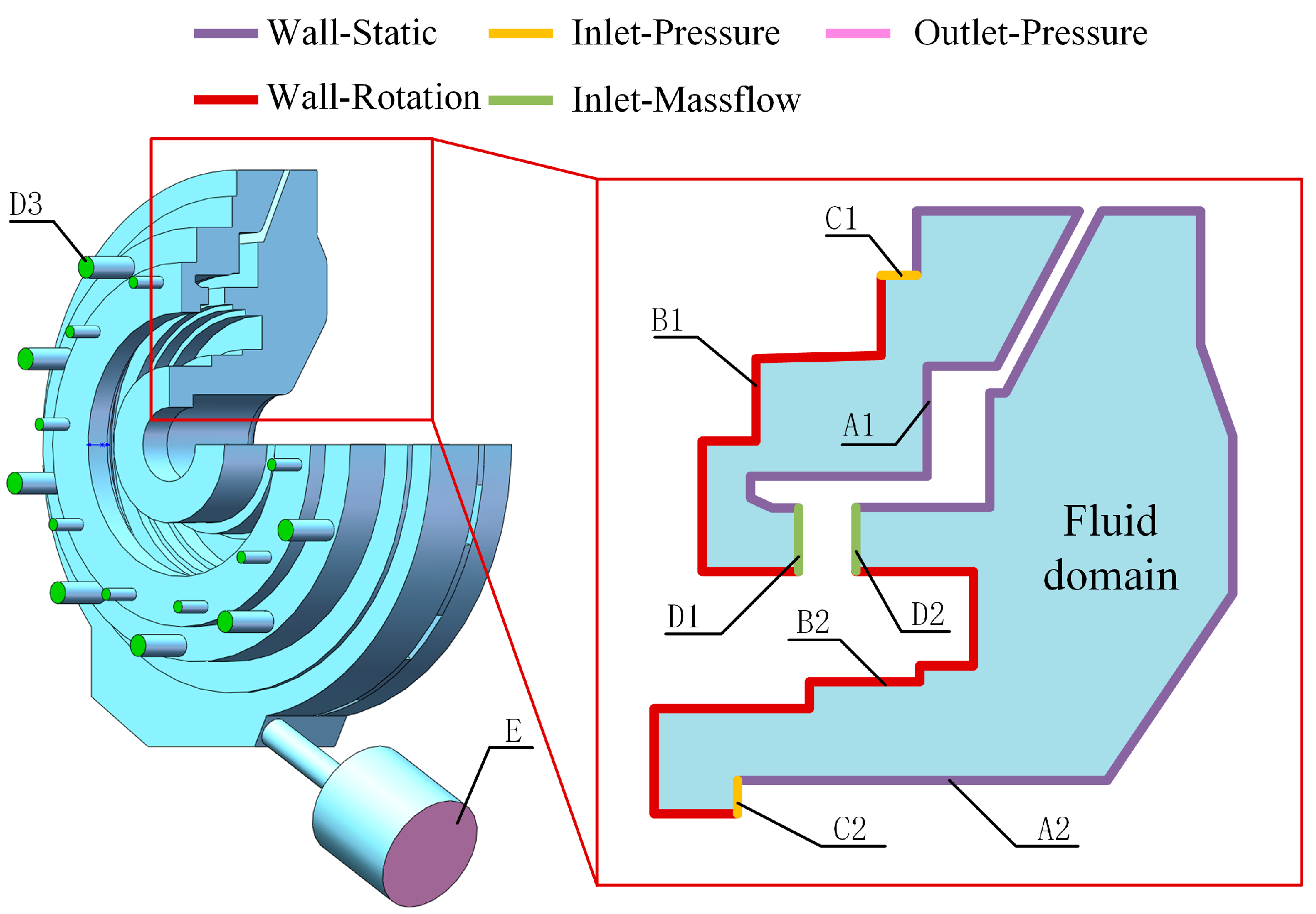
Figure 8 and Table 3 illustrate the calculation boundary positions and values. To simulate the scavenge pump suction, the outlet is set as a static pressure boundary condition with a specific pressure drop relative to the bearing chamber pressure. By reducing the pressure drop, the model demonstrates the correlation between lower bearing chamber pressure levels and reduced scavenging performance of the pump.

3.4. Oil Flow Characteristics Simulation Process

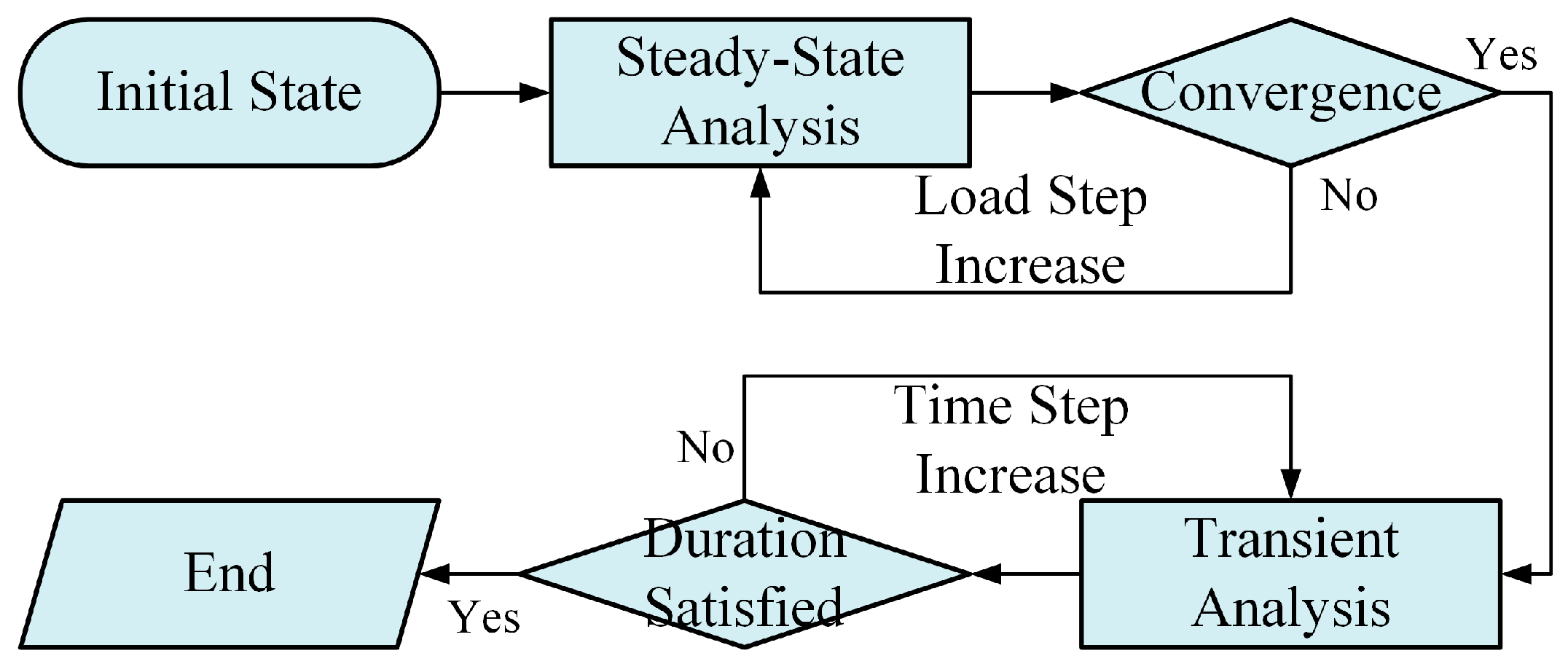
Figure 9 illustrates the simulation process of the oil flow characteristics. Given that the oil flow exhibits certain fluctuations during the actual oil collection process, the simulation process is divided into two main steps: steady-state analysis and transient analysis. Steady-state analysis is employed to obtain the approximate flow state of the oil in the bearing chamber. Based on these results, a transient analysis of the oil flow process is performed to evaluate the scavenging performance. To obtain a relatively stable steady-state solution, this study uses the change in lubricating oil mass within the flow domain between two consecutive load steps as the convergence criterion for the steady-state analysis.

4. Analysis of Oil Flow Characteristics and Oil Return Process

This study utilizes the VOF method with the k-ε RNG turbulence model to analyze two-phase interface processing techniques. The interface between the oil film and the air is captured, allowing characterization and analysis of oil flow behavior in both the chamber wall and the scavenge pipe.
Engineering experience revealed that the chamber pressure decreases significantly at high-altitude cruise state, reducing the pressure acting on the oil. This phenomenon leads to weakened oil film adhesion, causing partial detachment of oil from the upper bearing chamber walls. Within the scavenge pipe, inefficient oil accumulation occurs as the oil–air two-phase flow becomes indistinguishable due to turbulence, resulting in reduced scavenging performance. Consequently, this study selects the high-altitude cruise state (low-pressure rotor speed is 12,000 rpm and bearing chamber temperature is 100 °C) as the design point for oil flow characteristic simulations.

4.1. Pressure Distribution of Bearing Chamber

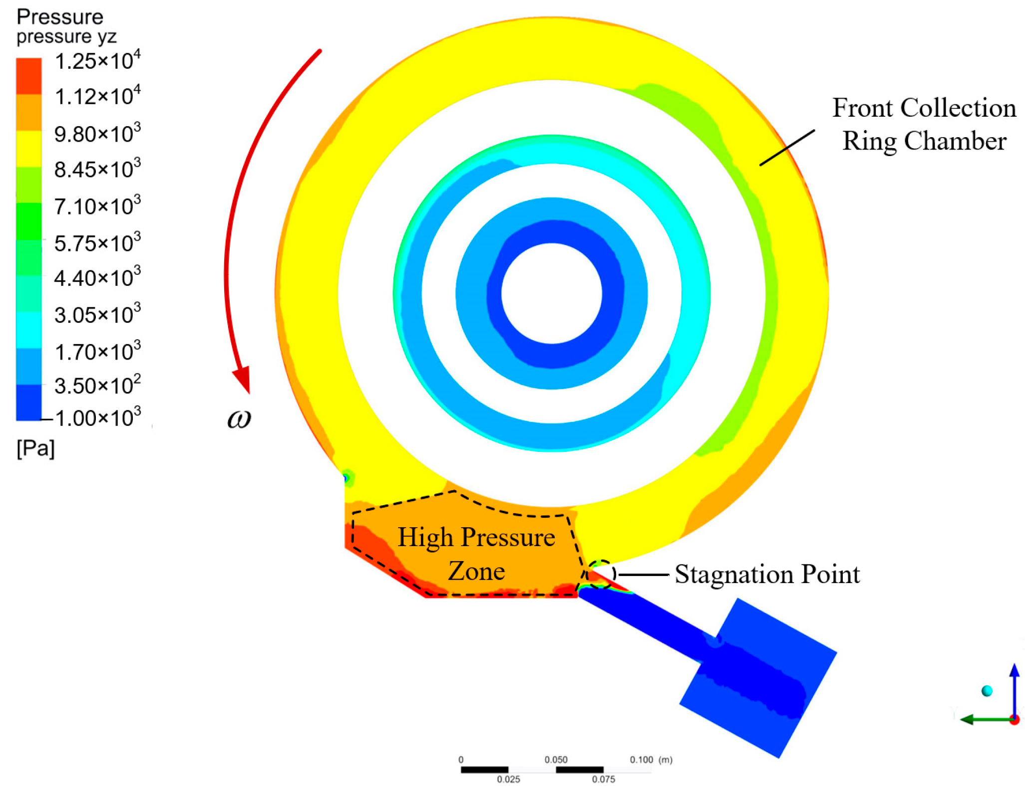
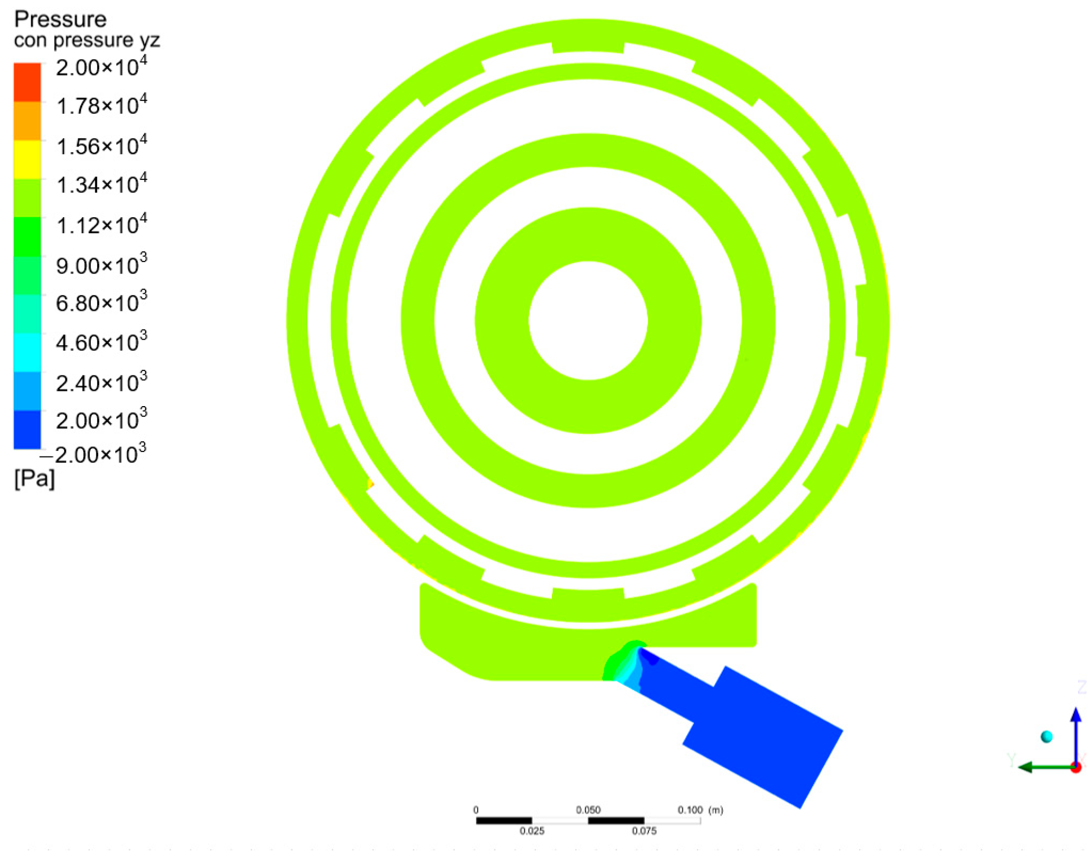
Figure 10 shows pressure (relative to static) on an axial cross-section through the front annulus and scavenge pipe axis. The figure reveals that pressure is relatively low in the front collection annulus. However, when the oil–air mixture enters the oil sump, its velocity decreases while pressure increases, creating a high-pressure zone within the oil sump. Additionally, as the oil–air mixture passes through the connection between the scavenge pipe and oil sump, the abrupt structural change causes local airflow stagnation, resulting in a localized high-pressure area, as indicated by the stagnation point shown in Figure 10.
This local high pressure drives flow into the scavenge pipe, aiding recovery. However, due to the connection between the sump and the front annulus, the high-pressure zone also tends to redirect oil flow toward the front annulus. Furthermore, the localized high pressure at the stagnation point affects the effective flow area within the scavenge pipe, impeding normal oil entry into the pipe.

4.2. Velocity Distribution of Bearing Chamber

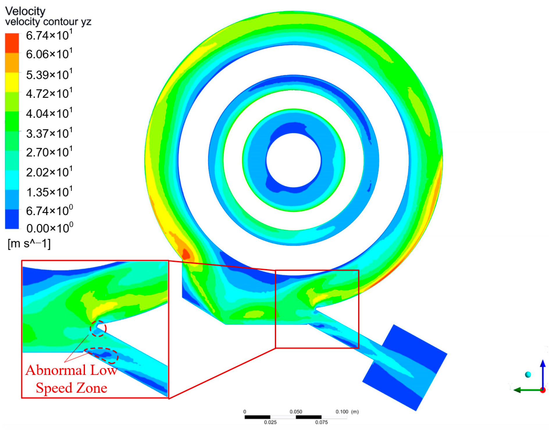
Figure 11 illustrates velocity distribution characteristics in the rear bearing chamber. In the front annulus, the oil–air mixture velocity is nearly uniform in the circumferential direction while following a radial distribution pattern where velocity increases with diameter. This occurs because fluid flow in the front annulus is primarily driven by the agitation of the rear journal of the low-pressure rotor, resulting in a consistent oil–air mixture velocity circumferentially. At larger diameters, the velocity of the rear journal of the low-pressure rotor increases, consequently driving the oil–air mixture at higher speed. However, it should be noted that the fluid flow in the oil sump exhibits more complex behavior, with an abnormally low-velocity zone appearing at the scavenge pipe inlet. This reduces the effective flow area of the scavenge pipe, negatively impacting scavenging performance.
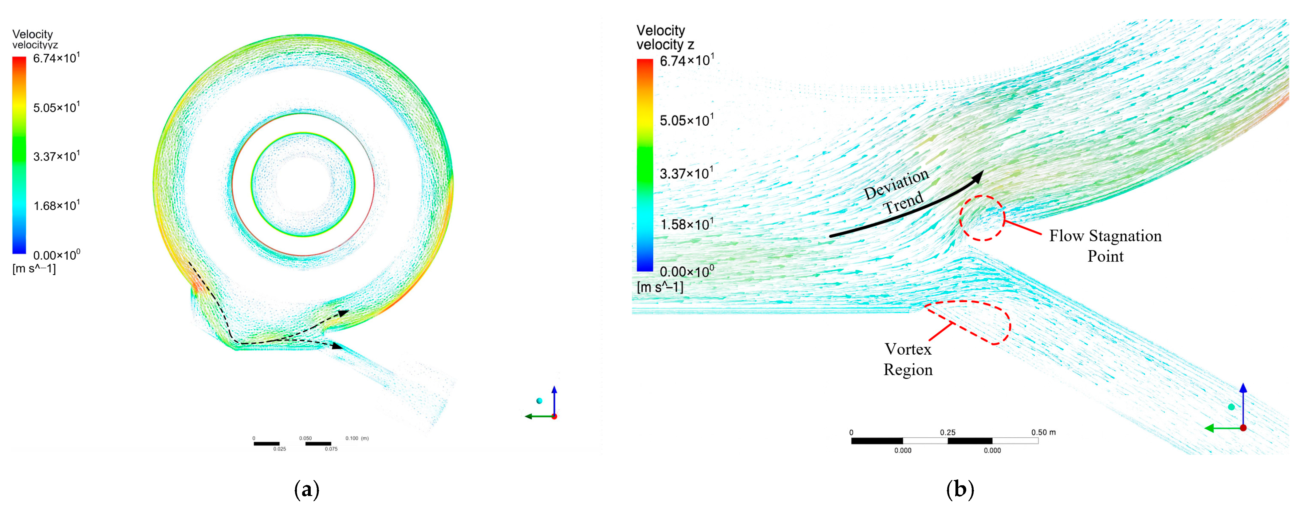
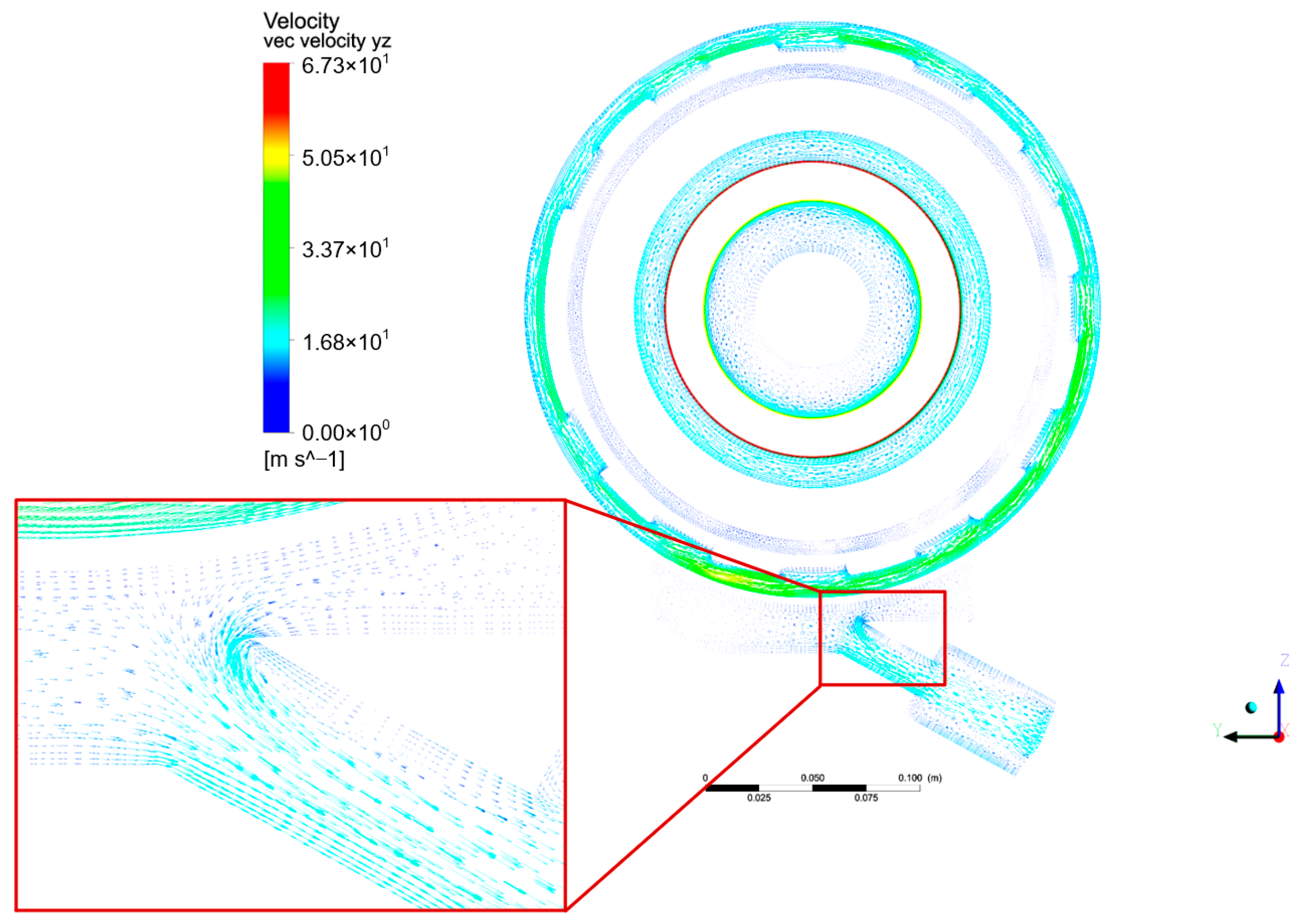
The flow velocity vector distribution characteristics of the rear bearing chamber, shown in Figure 12, provides a better explanation of the oil flow behavior in the oil return chamber. The dashed line in Figure 12a shows that flow entering from the oil return chamber splits: part flows into the scavenge pipe, and part recirculates to the front annulus. By examining the local flow domain shown in Figure 12b, two abnormally low-speed zones can be observed at the inlet of the scavenge pipe. One zone results from local vortex phenomena caused by the deviation in flow angle when oil enters the scavenge pipe, while the other stems from flow stagnation at the connection between the oil return chamber and scavenge pipe.
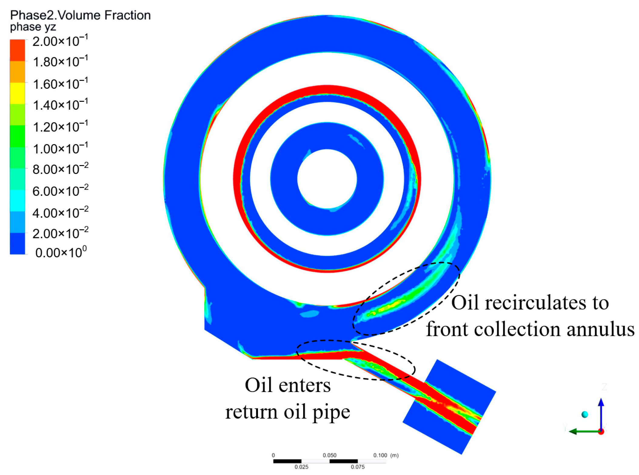
Figure 13 further illustrates that the oil simultaneously flows into both the scavenge pipe and the front collection annulus. Evidently, when oil cannot be discharged through the scavenge pipe and repeatedly enters the annulus, it has a higher probability of leaking from the bearing structural system, which adversely affects the normal oil return process. This phenomenon occurs for two reasons. First, the local low-pressure zone at the scavenge pipe inlet reduces the effective flow area of the scavenge pipe, preventing some oil from properly entering the scavenge pipe and causing it to turn back and flow into the front collection annulus. Second, as illustrated in Figure 14, a pressure gradient forms between the local high-pressure zone at the oil sump inlet and the low-pressure zone in the front collection annulus. Under the influence of this pressure gradient, the oil–air mixture in the oil sump tends to deflect toward the front collection annulus.
Based on the preceding analysis, the oil–air mixture in the oil sump exhibits two simultaneous flow tendencies: entering the scavenge pipe and recirculating to the front collection annulus. Consequently, when the suction capacity of the scavenge pump is insufficient, more oil recirculates into the front collection annulus rather than being drawn into the scavenge pipe, which negatively impacts the overall scavenging performance.

5. Evaluation of Scavenge Flow Characteristic

To improve rear chamber performance, the oil–air mixture must be more likely to enter the scavenge pipe than to recirculate to the front annulus. Consequently, we define a quantitative evaluation parameter to compare these tendencies and their impact on oil flow.
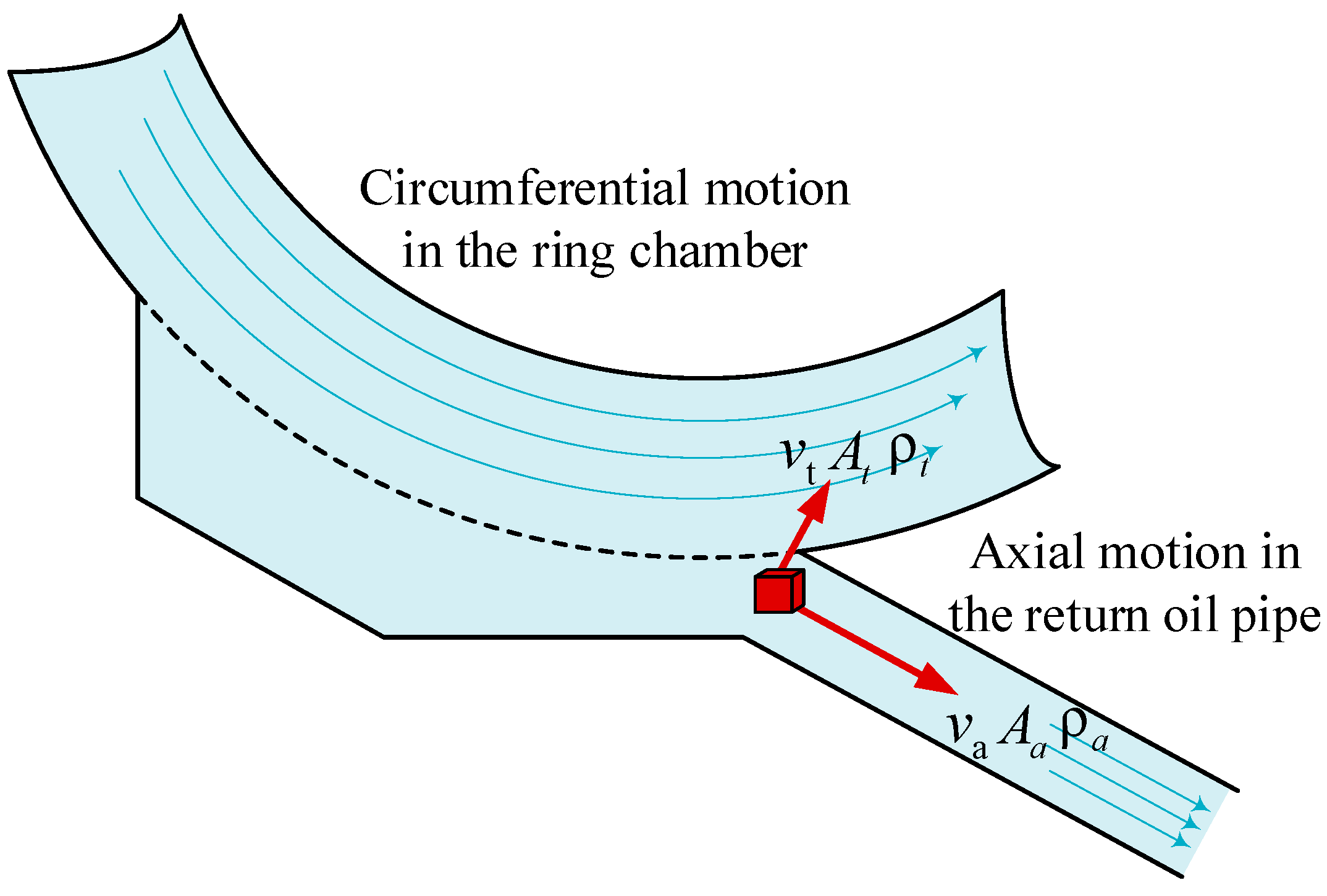
Figure 15 shows a schematic diagram of the local structure of the oil sump. Within a control volume located at the scavenge pipe inlet of the bearing chamber, two mutually orthogonal flow components are present. One is the axial inflow entering the scavenge pipe, with velocity component v a , cross-sectional area A a , and oil–air mixture density ρ a . The other is the tangential flow sweeping across the scavenge inlet along the annulus, with velocity component v t , cross-sectional area A t , and oil–air mixture density ρ t . The scavenge-flow characteristic is evaluated herein using the ratio of the momentum fluxes of these two flow components.
To avoid the influence of local non-uniformity in the velocity distribution, the area root mean square velocity (RMS velocity) is used to represent the equivalent mean velocity, with the axial and tangential velocity values defined as follows:
v a , r m s = 1 A a A a v a 2 d A   ,   v t , r m s = 1 A t A t v t 2 d A
On this basis, the momentum fluxes of the axial flow and the tangential flow are expressed as follows:
Φ a ( m ) = ρ a A a v a , r m s 2 , Φ t ( m ) = ρ t A t v t , r m s 2
The momentum ratio is defined as the ratio of the axial flow momentum flux to the tangential flow momentum flux, and is expressed as follows:
J m = Φ a ( m ) Φ t ( m ) = ρ a A a v a , r m s 2 ρ t A t v t , r m s 2
Therefore, the present study employs the momentum ratio to quantitatively assess the relative strength of the capability of the oil–air mixture to be scavenged into the return pipe compared with its tendency to re-enter the annulus.
When J m = 1 , the two effects are in equilibrium; when J m > 1 , scavenging dominates; and when J m < 1 , recirculation dominates. For ease of interpretation and to confine the evaluation parameter within the range [0, 1], this parameter can be further normalized as follows:
s i o ( m ) = J m 1 + J m = ρ a A a v a , r m s 2 ρ a A a v a , r m s 2 + ρ t A t v t , r m s 2
Assuming the same phase ( ρ a ρ t ), equal flow areas ( A a A t ), and a uniform velocity distribution ( v a , r m s v a , v t , r m s v t ), the expression can be simplified as follows:
s i o ( m ) = ( v a / v t ) 2 1 + ( v a / v t ) 2
In summary, a higher value of the evaluation parameter s i o ( m ) reflects a greater proportion of oil being directed into the scavenge pipe, indicating enhanced scavenging performance.
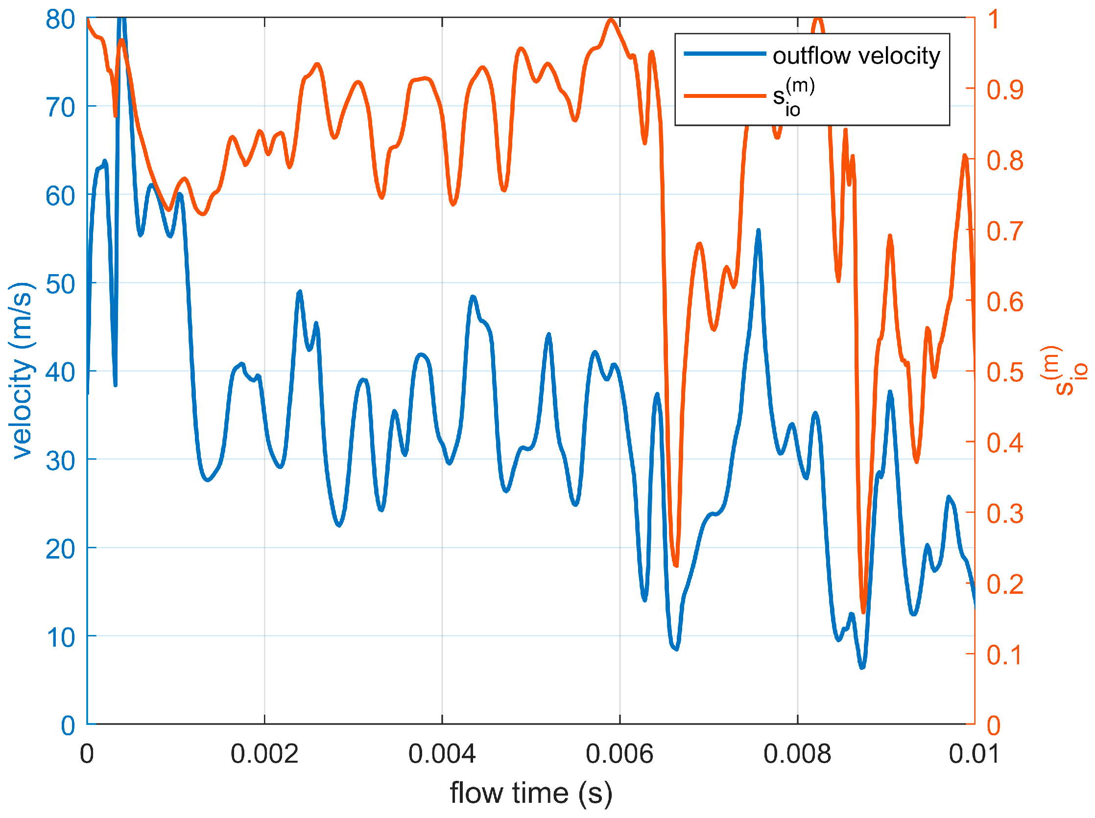
Figure 16 illustrates the temporal variation in the axial flow velocity at the scavenge pipe inlet and the corresponding evaluation parameter s i o ( m ) under the baseline configuration. The velocity remains consistently low during the observation period, primarily fluctuating between 10 m/s and 20 m/s, indicating that only a limited portion of the oil–air mixture is discharged directly through the scavenge pipe. The s i o ( m ) value is relatively stable at approximately 0.81, suggesting a moderate tendency for oil ingestion into the scavenge pipe, with a considerable fraction of the mixture potentially recirculating into the annulus.

6. Optimization Measures of Scavenging Performance

Analysis indicates that the rear bearing chamber exhibits poor oil flow characteristics. This issue stems from the direct connection between the oil sump and the front oil collection annulus. Due to the pressure difference between both chambers, some of the oil flows back into the front oil collection annulus, impeding proper oil return. In the following sections, we propose improvements to the geometric configuration of the rear bearing system to block the connection between the oil sump and the front oil collection annulus as much as possible, thereby enhancing the oil flow characteristics.
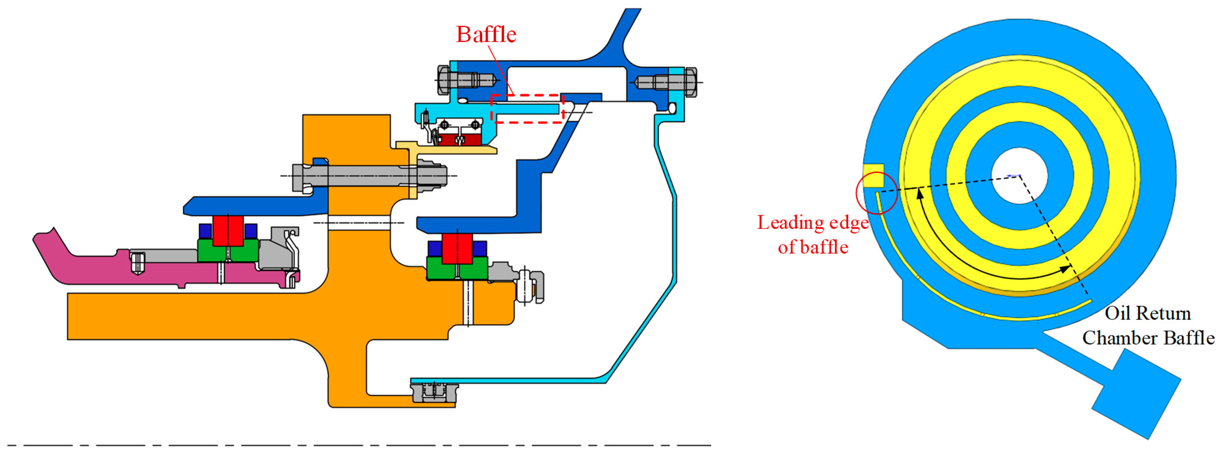
As illustrated in Figure 17, installing a baffle between the sump and the front annulus can partially mitigate the impact of oil–air mixture flow in the front annulus on oil deposition and accumulation in the sump. This improvement helps prevent the adverse effects that fluid circumferential movement within the annulus has on the oil return process.
Figure 18 illustrates the pressure distribution characteristics after installing a baffle. The baffle partially blocks the connection between the sump and the front annulus, enabling the chamber to maintain a relatively high static pressure. Simultaneously, the pressure distribution within the sump, particularly at the scavenge pipe inlet, becomes more uniform. The pressure gradient primarily acts in the circumferential direction, effectively preventing oil from moving radially due to pressure differences and thus facilitating oil return.
Figure 19 indicates that a more uniform sump pressure reduces sudden direction changes at entry, so oil aligns with the pipe and flows in more smoothly. While pressure difference between the sump and the annulus causes the oil–air mixture in region A to move circumferentially and exit the sump. This phenomenon primarily affects only a small amount of the mixture located above the main oil return flow path without impacting the oil return process. Additionally, since the oil–air mixture starts from zero velocity and gradually accelerates under the pressure difference, the flow rate remains low, preventing significant oil leakage.
In Figure 20, after adding the baffle, the evaluation parameter s i o ( m ) increases slightly compared with the baseline configuration in Figure 16, with values fluctuating mainly between 0.60 and 1.00 and averaging around 0.83, corresponding to an improvement of 2.5%. This enhancement results from the increased internal pressure in the oil sump and better alignment of the oil–air mixture flow with the scavenging pipe axis, which increases the proportion of inlet velocity directed toward the target direction. However, the time-history curves show substantial oscillations in both velocity and s i o ( m ) , indicating that the baffle improves average scavenging performance but also introduces instability under high-speed flow. Such fluctuations may locally impair oil recovery, suggesting the need for additional flow-stabilization measures.
To reduce the impact of circumferential airflow in the front annulus on oil accumulation in the sump, the sump is modified to the structure shown in Figure 21. This modification completely seals the interface between the oil sump and the front oil collection annulus to prevent fluid interaction. The oil circulating circumferentially within the front annulus must first enter the rear annulus, then combine and flow into the sump and pipe. In addition, the inlet is relocated from the edge to the mid-sump to avoid edge disturbance.
Figure 22 illustrates that the complete sealing of the interface between the sump and the front annulus eliminates fluid interaction. Consequently, the pressure distribution becomes uniform, exhibiting a pressure gradient directed from the sump towards the scavenge pipe. Under this pressure gradient, the oil–air mixture gradually accelerates and flows into the scavenge pipe for recovery.
Figure 23 reveals that, due to the lack of connection between the sump and the front annulus, the flow within the sump remains unaffected by the high circumferential flow in the front annulus. The inlet velocity of the scavenge pipe is relatively low, measuring 15.8 m/s. Under the influence of the pressure differential between the sump and the scavenge pipe outlet, a portion of the oil–air mixture is accelerated and flows into the scavenge pipe. Consequently, the velocity direction of the mixture aligns parallel to the central axis of the scavenge pipe, ensuring that the oil does not deviate from the scavenge direction. Additionally, since the flow velocities are generally low, the oil–air mixture does not generate excessive backflow eddies at the inlet during its flow into the scavenge pipe. These flow characteristics collectively enhance the scavenging performance.
In Figure 24, after implementing the structural improvement of the oil sump, s i o ( m ) further rises and stabilizes at about 0.95, representing an increase of 17.3% over the baseline and 14.5% over the baffle configuration. Although the velocity remains relatively low at 13–15 m/s due to the higher oil volume fraction and increased mixture density, the flow direction becomes significantly more stable, and temporal fluctuations in s i o ( m ) are minimal. This stability effectively suppresses turbulence generation near the scavenging pipe inlet, ensuring that the vast majority of the oil–air mixture is drawn into the scavenging pipe, thereby markedly improving scavenging capability.

7. Results

This study investigated oil–air two-phase scavenge flow in a rear bearing chamber with complex geometry and proposed a physics-grounded evaluation framework that links flow mechanisms to design choices and measurable performance. The main conclusions are as follows.
(1)
A normalized momentum–flux ratio evaluation parameter is proposed: In this study, an evaluation parameter s i o ( m ) is formulated based on the ratio of the momentum flux of the axial inflow into the scavenge pipe to that of the tangential crossflow in the annulus. By incorporating the cross-sectional RMS velocity and normalizing the result to the range [0, 1], this parameter physically reflects the competition between “entering the scavenge pipe” and “recirculating into the annulus,” while providing a quantifiable basis for comparing scavenging performance under different structural configurations. This method demonstrates strong applicability and interpretability for complex, realistic flow fields.
(2)
Simulation analysis of the oil flow characteristics for the baseline configuration: In the original structure, the evaluation parameter s i o ( m ) = 0.81 indicates a moderate tendency for the oil flow to enter the scavenge pipe, with a considerable proportion of the mixture recirculating into the front oil collection annulus. The root cause lies in the direct connection between the oil sump and the front oil collection annulus, which introduces a high tangential velocity flow field and an adverse pressure gradient, thereby reducing the effective flow area at the inlet.
(3)
Effect of the baffle modification (Improved Structure I): After installing a baffle between the oil sump and the front oil collection annulus, the average value of s i o ( m ) increases to 0.83, representing an improvement of 2.5% compared with the baseline. The internal pressure distribution becomes more uniform, and the flow direction is more favorable for the lubricating oil to enter the scavenge pipe. However, under high-speed flow conditions, significant fluctuations occur in both the inlet velocity and s i o ( m ) , which may locally reduce the scavenging performance, indicating that further optimization is needed to enhance flow stability.
(4)
Effect of full isolation and inlet position optimization (Improved Structure II): By completely isolating the oil sump from the front oil collection annulus and relocating the scavenge pipe inlet to the middle section, s i o ( m ) stabilizes at approximately 0.95, representing a 17.3% improvement over the baseline and 14.5% improvement over the baffle configuration. This structural arrangement effectively eliminates the interference from high-speed tangential flows, resulting in a stable flow direction with minimal fluctuations, thereby significantly enhancing scavenging performance.
(5)
The evaluation parameter s i o ( m ) proposed in this study provides a quantitative measure for assessing the scavenge flow characteristics of bearing chambers and can be applied directly to compare and select alternative structural configurations. The two improvement schemes demonstrate that geometrically isolating regions of high circumferential flow and optimizing the scavenge-inlet location markedly increase the proportion of momentum flux and enhance flow stability, thereby improving scavenge efficiency, reducing oil residence time and lowering leakage risk. The proposed methodology and design principles offer practical guidance for optimizing lubrication systems in high DN bearing chambers and promote improvements in aero-engine bearing chamber reliability.

Author Contributions

Conceptualization, Y.M. and W.Z.; methodology, W.Z. and X.C.; software, W.Z.; validation, Y.M. and X.C.; formal analysis, W.Z. and X.C.; investigation, W.Z.; resources, W.Z., X.C. and Z.L.; data curation, X.C., Z.L. and J.H.; writing—original draft preparation, W.Z. and X.C.; writing—review and editing, Y.M., W.Z., X.C. and Z.L.; visualization, Y.M., X.C. and J.H.; supervision, Y.M. and W.Z.; project administration, X.C. and J.H.; funding acquisition, X.C. All authors have read and agreed to the published version of the manuscript.

Funding

This research was financially supported by the National Science and Technology Major Project (J2022-IV-0003-0020).

Data Availability Statement

The original contributions presented in the study are included in the article; further inquiries can be directed to the corresponding author.

Conflicts of Interest

Zihao Leng is employed by AECC Shenyang Engine Research Institute and AECC Key Laboratory of Power Transmission Technology on Aero-engine. The remaining authors declare that the research was conducted in the absence of any commercial or financial relationships that could be construed as potential conflicts of interest.

References

  1. Hong, J.; Ma, Y.H.; Zhang, D.Y. Overall Structure Design and Dynamic Analysis of Aero Gas Turbine; Beijing University of Aeronautics and Astronautics Press: Beijing, China, 2014; pp. 230–276. ISBN 978-7-5124-1360-3. [Google Scholar]
  2. Wang, W.; Wang, Y.M.; Wang, Z.S.; Wang, H.W.; Zhu, Z.J.; Yang, J.G.; Shen, X.M.; Wu, N.X.; Wu, L.F.; Lu, J.W.; et al. Aero-Engine Design Manual, 12th ed.; Aviation Industry Press: Beijing, China, 2001; pp. 429–432. ISBN 7-80134-943-1. [Google Scholar]
  3. Chandra, B.W.; Collicott, S.H.; Munson, J.H. Experimental Optimization of Rolls-Royce AE3007 Sump Design. In Proceedings of the ASME Turbo Expo 2017: Turbomachinery Technical Conference and Exposition, Charlotte, NC, USA, 26–30 June 2017. [Google Scholar] [CrossRef]
  4. Hirt, C.W.; Nichols, B.D. Volume of fluid (VOF) method for the dynamics of free boundaries. J. Computational. Phys. 1981, 39, 201–225. [Google Scholar] [CrossRef]
  5. Chang, Y.C.; Hou, T.Y.; Merriman, B.; Osher, S. A Level Set Formulation of Eulerian Interface Capturing Methods for Incompressible Fluid Flows. Computational. Phys. 1996, 124, 449–464. [Google Scholar] [CrossRef]
  6. Reynolds, O. On the Theory of Lubrication and Its Application to Mr. Beauchamp Tower’s Experiments, Including an Experimental Determination of the Viscosity of Olive Oil. Philos. Trans. R. Soc. Lond. 1886, 177, 157–234. [Google Scholar] [CrossRef]
  7. Farrall, M.; Simmons, K.; Hibberd, S.; Gorse, P. A Numerical Model for Oil Film Flow in an Aero-Engine Bearing Chamber and Comparison with Experimental Data. J. Eng. Gas Turbines Power 2006, 128, 111–117. [Google Scholar] [CrossRef]
  8. Wang, C.; Morvan, H.P.; Hibberd, S.; Cliffe, K.A. Thin Film Modelling for Aero-Engine Bearing Chambers. In Proceedings of the ASME Turbo Expo 2011: Turbine Technical Conference and Exposition, Vancouver, BC, Canada, 12 October 2010; pp. 277–286. [Google Scholar] [CrossRef]
  9. Singh, K.; Sharabi, M.; Jefferson-Loveday, R.; Ambrose, S.; Eastwick, C.; Cao, J.; Jacobs, A. Modeling of Partially Wetting Liquid Film Using an Enhanced Thin Film Model for Aero-Engine Bearing Chamber Applications. J. Eng. Gas Turbines Power 2021, 143, 041001. [Google Scholar] [CrossRef]
  10. Simmons, K.; Hibberd, S.; Wang, Y.; Care, L. Numerical Study of the Two-Phase Air/Oil Flow Within an Aero-Engine Bearing Chamber Model Using a Coupled Lagrangian Droplet Tracking Method. In Proceedings of the ASME 2002 Pressure Vessels and Piping Conference, Vancouver, BC, Canada, 5–9 August 2002; pp. 325–331. [Google Scholar] [CrossRef]
  11. Kakimpa, B.; Morvan, H.P.; Hibberd, S. The Numerical Simulation of Multi-Scale Oil Films Using Coupled VOF and Eulerian Thin-Film Models. In Proceedings of the ASME Turbo Expo 2016: Turbomachinery Technical Conference and Exposition, Seoul, Republic of Korea, 13–17 June 2016. [Google Scholar] [CrossRef]
  12. Ren, G.Z. Investigation on Flow and Heat Transfer Characteristics in Aero-Engine Bearing Chambers under Oil-Gas Two-Phase Flow Conditions and Optimization Design of Scavenge Structures. Ph.D. Thesis, Northwestern Polytechnical University, Xi’an, China, December 2016. [Google Scholar]
  13. Li, W. Numerical Study on Flow Characteristics of Oil-Air Two-Phase Flow in Bearing Chambers. Master’s Thesis, Nanjing University of Aeronautics and Astronautics, Nanjing, China, December 2016. [Google Scholar]
  14. Lee, C.W.; Palma, P.C.; Simmons, K.; Pickering, S.J. Comparison of CFD and PIV Data for the Airflow in an Aero-Engine Bearing Chamber. In Proceedings of the ASME Turbo Expo 2004: Power for Land, Sea, and Air, Vienna, Austria, 14–17 June 2004; pp. 97–105. [Google Scholar] [CrossRef]
  15. Chen, B.; Chen, G.D.; Zhang, Y.H. Numerical Simulation of Gas-Phase Velocity Field in Aero-engine Bearing Chambers. Mech. Sci. Technol. Aerosp. Eng. 2012, 8, 1241–1246. [Google Scholar] [CrossRef]
  16. Lü, Y.G.; Zhang, M.H.; Liu, Z.X.; Hu, J.P. Numerical study and validation for two-phase flow of oil and gas in Aero-Engine bearing chambers. J. Aerosp. Power 2014, 29, 2751–2757. [Google Scholar] [CrossRef]
  17. Wang, T.; Chen, G.D.; Chen, B. Theoretical and Experimental Study on Flow Field of Gas-Phase Medium in Aero-Engine Bearing Chambers. J. Aerosp. Power 2014, 11, 2767–2773. [Google Scholar] [CrossRef]
  18. Yang, P.J.; Lu, P.; Fang, L.L.; Wang, X.Y. Effect of structural parameters of oil return groove on oil-air two-phase flow in bearing chambers. J. Jiangsu Univ. (Nat. Sci. Ed.) 2019, 40, 643–648. [Google Scholar]
  19. Crouchez-Pillot, A.; Morvan, H.P. CFD Simulation of an Aero-engine Bearing Chamber Using an Enhanced Volume of Fluid (VOF) Method: An Evaluation Using Adaptive Meshing. In Proceedings of the ASME Turbo Expo 2014: Turbine Technical Conference and Exposition, Düsseldorf, Germany, 16–20 June 2014. [Google Scholar] [CrossRef]
  20. Chandra, B.; Collicott, S.H.; Munson, J.H. Scavenge Flow in a Bearing Chamber with Tangential Sump Off-Take. J. Eng. Gas Turbines Power 2013, 135, 032503. [Google Scholar] [CrossRef]
  21. Chandra, B.; Simmons, K.; Pickering, S.; Tittel, M. Factors Affecting Oil Removal From an Aero-Engine Bearing Chamber. In Proceedings of the ASME Turbo Expo 2010: Power for Land, Sea, and Air, Glasgow, UK, 14–18 June 2010; pp. 219–228. [Google Scholar] [CrossRef]
  22. Collicott, S.H.; Wiedemann, N. Study of Gas/Liquid Behavior Within an Aero-engine Bearing Chamber. J. Eng. Gas Turb. Power 2013, 135, 051201. [Google Scholar] [CrossRef]
  23. Chandra, B.; Simmons, K. Transient Two-Phase Effects in an Aero-engine Bearing Chamber Scavenge Test Rig. In Proceedings of the ASME 2014 International Mechanical Engineering Congress and Exposition, Montreal, QC, Canada, 14–20 November 2014. [Google Scholar] [CrossRef]
  24. Simmons, K.; Chandra, B. Experimental Investigation Into the Performance of Shallow Aero-engine Off-Takes. In Proceedings of the ASME Turbo Expo 2014: Turbine Technical Conference and Exposition, Düsseldorf, Germany, 16–20 June 2014. [Google Scholar] [CrossRef]
  25. Kurz, W.; Dullenkopf, K.; Bauer, H.J. Capacitive Film Thickness Measurements in a Ventless Aero-Engine Bearing Chamber—Influence of Operating Conditions and Offtake Design. J. Eng. Gas Turbines Power 2013, 135, 112504. [Google Scholar] [CrossRef]
  26. Kurz, W.; Dullenkopf, K.; Bauer, H.J. Influences on the Oil Split Between the Offtakes of an Aero-Engine Bearing Chamber. In Proceedings of the ASME Turbo Expo 2012: Turbine Technical Conference and Exposition, Copenhagen, Denmark, 11–15 June 2012; pp. 2251–2259. [Google Scholar] [CrossRef]
Figure 1. Structural system of a specific turbofan engine configuration.
Lubricants 13 00381 g001
Figure 2. Structural schematic of the rear bearing chamber: 1—Rear journal of high-pressure rotor; 2—No. 4 bearing; 3—Axial vent hole; 4—Graphite seal; 5—Oil sump; 6—Turbine rear bearing frame; 7—No. 5 bearing; 8—Rear baffle; 9—Graphite seal; 10—Rear journal of low-pressure rotor; 12—Front/rear oil collection annulus vent hole; I—Front oil collection annulus; II—Rear oil collection annulus.
Lubricants 13 00381 g002
Figure 3. Oil flow process in the rear bearing chamber.
Lubricants 13 00381 g003
Figure 4. Two-dimensional structure diagram of bearing chamber.
Lubricants 13 00381 g004
Figure 5. Fluid domain–solid domain distribution of the rear bearing structural system.
Lubricants 13 00381 g005
Figure 6. Fluid domain grid division of the rear bearing structural system.
Lubricants 13 00381 g006
Figure 7. Mesh independence verification.
Lubricants 13 00381 g007
Figure 8. Calculation boundary condition setting of oil flow characteristic simulation model.
Lubricants 13 00381 g008
Figure 9. Simulation process of oil flow characteristics.
Lubricants 13 00381 g009
Figure 10. Pressure distribution characteristics (unit: Pa).
Lubricants 13 00381 g010
Figure 11. Velocity distribution characteristics (unit: m/s).
Lubricants 13 00381 g011
Figure 12. Velocity vector distribution characteristics (unit: m/s). (a) Fluid domain; (b) Local flow domain of the oil return chamber.
Lubricants 13 00381 g012
Figure 13. Distribution characteristics of the oil.
Lubricants 13 00381 g013
Figure 14. Corresponding relationship between pressure distribution and velocity distribution.
Lubricants 13 00381 g014
Figure 15. Schematic diagram of scavenge flow characteristic evaluation parameters.
Lubricants 13 00381 g015
Figure 16. Temporal variation in velocity and evaluation parameter s i o ( m ) .
Lubricants 13 00381 g016
Figure 17. Improved structure I with baffle.
Lubricants 13 00381 g017
Figure 18. Pressure distribution characteristics with baffle.
Lubricants 13 00381 g018
Figure 19. Velocity distribution characteristics with baffle.
Lubricants 13 00381 g019
Figure 20. Temporal variation in velocity and evaluation parameter s i o ( m ) (Improved structure I).
Lubricants 13 00381 g020
Figure 21. The second improved structure.
Lubricants 13 00381 g021
Figure 22. Pressure distribution characteristics.
Lubricants 13 00381 g022
Figure 23. Velocity vector distribution characteristics.
Lubricants 13 00381 g023
Figure 24. Temporal variation in velocity and evaluation parameter s i o ( m ) (Improved structure II).
Lubricants 13 00381 g024
Table 1. Bearing chamber geometry dimensions.
GeometryDimension
Bearing chamber diameter D 300 mm
Oil sump depth h 15 mm
Vent pipe length l 1 70 mm
Vent pipe diameter d 1 16 mm
Scavenge pipe length l 2 70 mm
Scavenge pipe diameter d 2 16 mm
Scavenge pipe inclination angle α 30°
Oil sump width w 120 mm
Table 2. Fluid property parameters.
NumberingTypeDensity (kg/m3)Viscosity
(kg/(m·s))
Tension
Coefficient (N/m)
Phase 1Air1.2271.790 × 10−50.04
Phase 2Oil 2380974.9004.845 × 10−3
Table 3. Calculation boundary conditions.
NumberBoundary TypeEffectCorresponding Parameter
A1Wall–StaticSimulation of constraint effect of the stationary wall-
A2
B1Wall–MovingSimulation of the rotating wall, driving oil/air
circumferential motion
Low-pressure rotor working speed 12,000 rpm
B2
C1Inlet–PressureSimulate graphite sealing structure,
controlling static pressure in the chamber
Measured static pressure of the chamber 59 kPa
C2
D1Inlet–Mass flowSimulating No. 5 bearing oil supply60 g/s
D2
D3Simulating No. 4 bearing oil supply169 g/s
EOutlet–PressureSimulation of scavenge pump for oil suction1 kPa lower than the chamber
Disclaimer/Publisher’s Note: The statements, opinions and data contained in all publications are solely those of the individual author(s) and contributor(s) and not of MDPI and/or the editor(s). MDPI and/or the editor(s) disclaim responsibility for any injury to people or property resulting from any ideas, methods, instructions or products referred to in the content.