Article

Effect of Laser Scanning Speed on Microstructure and Wear Resistance of TiC-TiB2-Reinforced 316L Laser-Clad Coatings

1
School of Mechanical Engineering, Northeast Electric Power University, No. 169 Changchun Road, Jilin 132012, China
2
International Shipping Research Institute, Jiujiang Polytechnic University of Science and Technology, Jiujiang 332020, China
3
School of Intelligent Manufacturing, Guangzhou Polytechnic University, No.1342 Shiliang Road, Guangzhou 511483, China
*
Author to whom correspondence should be addressed.
Lubricants 2025, 13(8), 359; https://doi.org/10.3390/lubricants13080359
Submission received: 22 July 2025 / Revised: 7 August 2025 / Accepted: 9 August 2025 / Published: 13 August 2025

Abstract

To enhance the wear resistance of laser-clad coatings, this study investigates the underlying modulation mechanisms of scanning speed on the microstructure and properties of TiC-TiB2-reinforced 316L stainless steel composite coatings. TiC/TiB2 particle-reinforced 316L stainless steel composite coatings were fabricated on 45# steel substrates via laser cladding. Our analysis reveals that scanning speed critically governs the thermal cycle of the melt pool, thereby modulating the coating’s microstructure and properties: Lower scanning speeds prolong melt pool duration, consequently intensifying ceramic particle dissolution, coarsening, and tendencies toward agglomeration and settling. Conversely, higher scanning speeds promote rapid solidification, which both preserves ceramic particles and refines the matrix grains. With increasing scanning speed, accelerated melt pool cooling rates drive a microstructural transition from coarse dendrites to refined equiaxed grains, accompanied by dramatically enhanced uniformity in ceramic particle distribution. Coatings deposited at higher scanning speeds exhibit a 22% increase in hardness compared to those at lower speeds. Wear resistance evolution parallels this hardness trend: at 480 mm/min scanning speed, wear reduction can be expected, with the wear volume decreasing by 58.60% and the friction coefficient reducing by 42.1% relative to 120 mm/min.

1. Introduction

Laser cladding technology is a green and efficient surface repair technology [1]. It has the advantages of good metallurgical bonding, controllability, and high efficiency [2,3] compared with traditional surface repair techniques such as welding [4], spraying [5], and plating [6]. In recent years, austenitic 316L stainless steel has been widely recognized as a preferred engineering material, owing to its exceptional mechanical properties, outstanding corrosion resistance, and relatively low cost [7]. However, its low hardness and poor tribological properties limit its application under heavy wear conditions [8]. The introduction of ceramic particle reinforcement into metal matrix composites (MMCs) has been demonstrated as a key strategy for significantly enhancing the strength of such coatings [9,10,11]. V. Tiwari et al. [12] investigated the effects of TiC content variation (10, 20, and 30 vol%) on the microstructure, hardness, and wear performance of Stellite 6 metal matrix composites (MMCs). Their study demonstrated that 30 vol% TiC reinforcement enhanced the coating hardness by 44.2% while simultaneously improving the wear resistance of the Stellite 6 coating. To enhance the wear resistance of Ti6Al4V alloy surfaces, Nianlong L et al. [13] synthesized TiB-reinforced titanium matrix composite (TMC) coatings with varying TiB2 content via in situ laser cladding. Their results demonstrated that increasing TiB2 content profoundly enhanced the microstructure, solidification behavior, hardness, and wear performance of the TMC coatings. Y. Liu et al. [14] fabricated TiB2-reinforced 316L composites (0–6 wt%) via laser cladding additive manufacturing. Their work demonstrated that 6 wt% TiB2 reinforcement achieved a 25% increase in Vickers hardness and a 29% enhancement in yield strength. Metal matrix composite (MMC) coatings exhibit superior properties unattainable with monolithic coatings, owing to the incorporation of metallic or ceramic reinforcements [15,16]. However, conventional monodisperse ceramic particles—such as TiC [17], TiB2 [18], or WC [19]—while effective for enhancing hardness, are prone to fracture under external loading due to their intrinsic brittleness [20]. Moreover, these reinforcements often exhibit poor plastic compatibility and weak interfacial bonding with the alloy matrix. This results in severe stress concentrations and promotes crack initiation/propagation along the interfaces, ultimately leading to matrix embrittlement [21,22]. Nano-TiC effectively reduces interfacial defects, and refines grain structure by decreasing the average grain size [23]. Concurrently, micro-TiB2 acts as crack-arresting sites via pull-out and bridging mechanisms [24]. This synergistic interaction establishes multiscale ceramic hybrids as a promising strategy to overcome the aforementioned challenges.
The goal of this research was to evaluate the governing mechanisms by which laser cladding process parameters dictate the microstructure and tribological properties of TiC–TiB2-reinforced 316L stainless steel composite coatings. A key finding reveals that laser scanning velocity, as the dominant processing parameter, critically controls the ultimate coating characteristics by dramatically altering the thermal cycling history of the molten pool.

2. Materials and Methods

2.1. Sample Preparation

Grade 45 steel substrates (50 mm × 30 mm × 10 mm) were selected for laser cladding in this study, with their chemical composition detailed in Table 1. Prior to cladding, Grade 45 steel substrates were surface-polished using abrasive paper. The coating feedstock consisted of 316L stainless steel powder, TiC, and TiB2 powders, with mean particle sizes and purity specified in Table 2. The 316L powder (containing Fe, C, Si, Cr, Ni, Mn, and Mo) provides exceptional corrosion resistance; its full chemical composition is detailed in Table 3. Specifically, TiC (3 wt%, 50 nm) and TiB2 (10 wt%, 1 μm) were blended with the 316L powder. To ensure homogeneous composite feedstock, the powders were manually ground in an agate mortar for 30 min. The manual grinding protocol effectively mitigated segregation, as evidenced by the consistent dispersion of reinforcing phases across all scanning velocities—particularly under rapid solidification conditions (480 mm/min) where agglomeration is suppressed [25].
A scanning velocity gradient of 120–480 mm/min was employed, guided by Liang et al.’s [1] parametric optimization framework for ceramic-reinforced laser-clad systems and through multiple experiments. This experimental matrix maintained a constant laser power of 1200 W, TiB2 content of 10 wt%, and TiC content of 3 wt%.

2.2. Laser Cladding Process

A CO2 laser system (DL-HL-T2000B, Continental Laser; λ = 10.6 μm, Pmax = 2000 W) was employed for cladding experiments. The integrated CNC machine governed the entire laser deposition process with fixed parameters set at 30% overlap ratio and 3 mm beam diameter. Pre-placed specimens underwent laser cladding, yielding as-clad coatings for subsequent characterization.

2.3. Sample Characterization

Specimens were ground, polished, and ultrasonically cleaned in anhydrous ethanol for 15 min followed by drying. Selective etching was achieved by swabbing cross-sections with aqua regia-saturated cotton swabs for 40 s in a fume hood, succeeded by deionized water rinsing, secondary ultrasonic cleaning, and drying to prepare metallographic samples. Aqua regia preferentially etches γ-Fe phases, revealing dendritic boundaries in 316L composites per ASTM E407 [26]. Microstructural analysis of cross-sections and wear tracks was conducted using a JSM-IT500 field-emission scanning electron microscope (FE-SEM), coupled with energy-dispersive X-ray spectroscopy (EDS) elemental mapping to quantitatively characterize spatial distribution patterns of chemical constituents within the coating.
The appropriate scanning rate and step size in XRD measurements are critical for enhancing peak resolution, thereby facilitating accurate phase analysis [27]. Phase composition and crystallographic analysis of the coating were conducted using a TD-3500 X-ray diffractometer (XRD) with Cu Kα radiation (λ = 1.5406 Å). The measurements were performed in continuous scan mode with θ–2θ coupled geometry under the following operational parameters: 40 kV accelerating voltage, 200 mA tube current, 2θ angular range of 20–80, step width of 0.02, and scan rate of 4.08/min

2.4. Vickers Hardness Testing

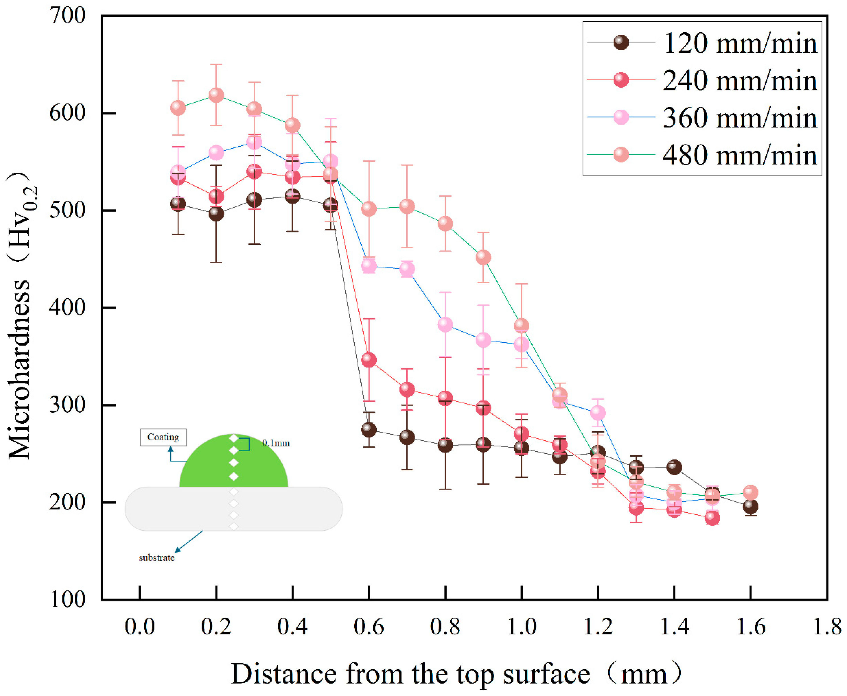
Vickers hardness profiling across coating cross-sections was performed at ambient temperature using an HXD-1000TMC/LCD Vickers hardness profiling under a 200 gf load with 10 s dwell time. Depth-resolved measurements commenced at 0.1 mm beneath the surface, with three parallel measurement points spaced at 0.1 mm intervals per depth tier (inter-tier spacing: 0.1 mm). The arithmetic mean of triplicate measurements at each depth was recorded to construct hardness/depth distribution profiles. Hardness values are reported as mean ± standard deviation from three measurements per depth.

2.5. Wear Resistance Testing

Dry sliding wear tests were performed with one specimen per scanning speed variant due to the high cost of coating fabrication. For specimens prepared at different scanning speeds, dry sliding wear tests on laser-clad specimens were conducted using an MGW-02 high-speed reciprocating tribometer. A GCr15 steel counterface was employed under unlubricated ambient conditions with the following parameters: 30 N applied load, 10 Hz oscillation frequency, 3 mm stroke length, and 40 min test duration. GCr15 counterface (700 ± 50 HV) was selected to simulate industrial bearing components, with the hardness ratio to coating covering typical wear scenarios.
Post-test specimens were ultrasonically cleaned in anhydrous ethanol and blow-dried. Wear scar dimensions (length/width) were measured with a digital vernier caliper through six repeated measurements, with the arithmetic mean value recorded. Figure 1 illustrates the schematic for wear volume calculation, which was subsequently determined using the following equation.
The wear rate calculation formula adopted in this experiment is expressed as
θ = arcsin L A B 2 R
S 1 = 2 θ π R 2 2 π = θ 2
S 2 = 1 2 L A B · R · c o s θ
S 3 = S 1 S 2
V = S 3 · l A B
ω = V F · S
where θ denotes the central angle corresponding to the wear scar width, L A B represents the wear scar width, S 1 is the sector area, S 2 designates the area of ΔOAB, S 3 indicates the wear scar cross-sectional area, l A B denotes the wear scar length, ω signifies the mass loss (g), F is the applied normal load (N), and S corresponds to the sliding distance (m).

3. Results and Discussion

3.1. Phase Analysis by XRD

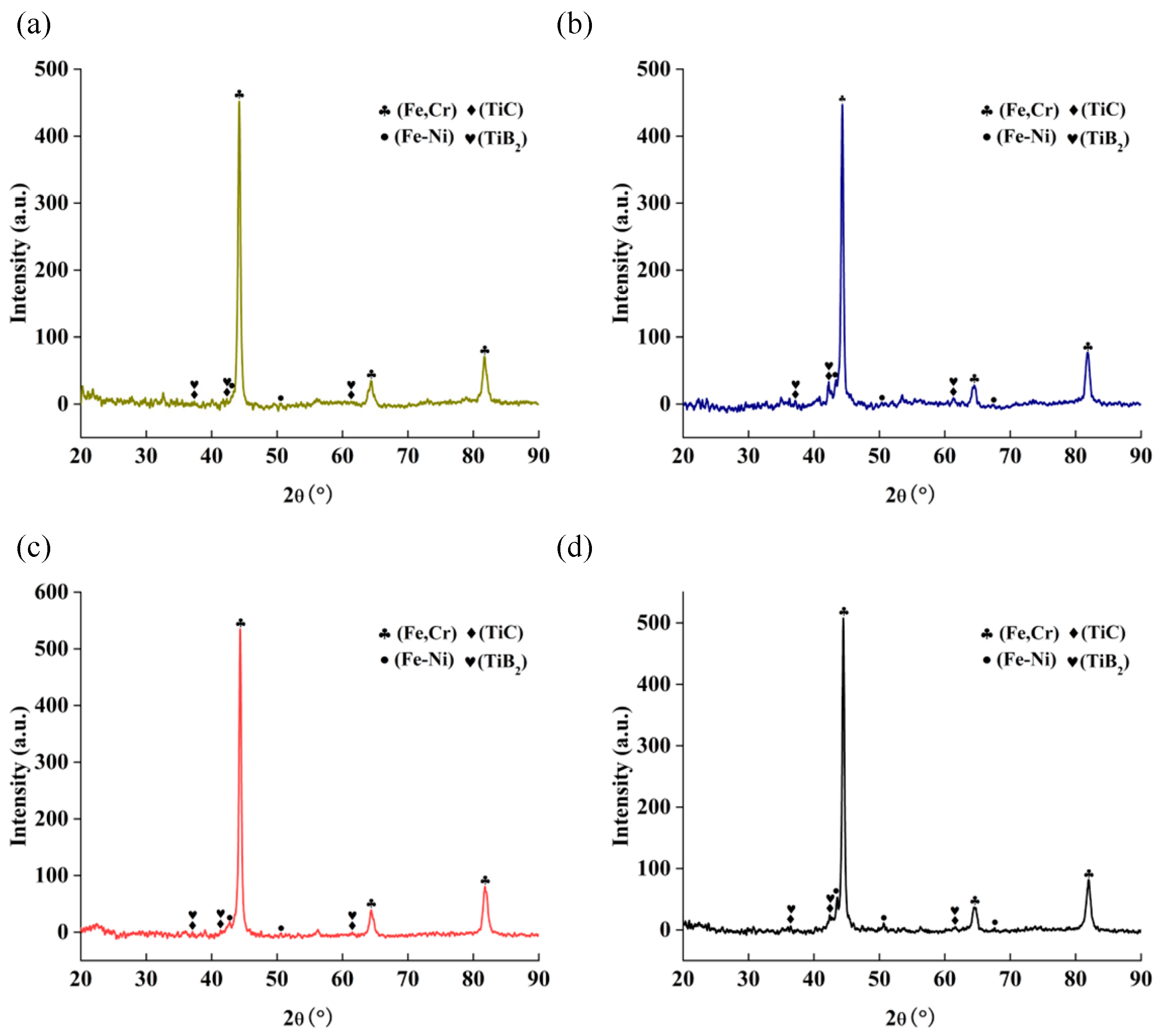
Figure 2 presents the XRD patterns of composite coatings fabricated at different scanning speeds. The coatings consist primarily of TiB2, TiC, TiNi, BCC-structured solid solution (Fe-Cr), and FCC-structured solid solution (Fe-Ni) phases. Notably, the weak diffraction peak intensities of TiB2 and TiC ceramic phases in the clad layer arise primarily from high-temperature dissolution during laser cladding (particularly at low scanning speeds), and the nanoscale dimensions of TiC particles (~50 nm), resulting in XRD peak broadening [28,29]. This signal attenuation is further compounded by the low volume fraction of added TiC/TiB2 reinforcement, rendering their diffraction signatures susceptible to masking by the intense Fe peaks from the high-content 316L matrix. While higher scanning speeds improve particle distribution uniformity, they fail to fully mitigate dissolution effects and nanoscale-induced peak broadening. The low volume fraction of added TiC/TiB2 reinforcement inherently weakens diffraction signals, rendering them susceptible to masking by intense Fe peaks from the high-content 316L matrix. While higher scanning speeds improve distribution uniformity, they fail to fully mitigate dissolution effects and nanoscale-induced peak broadening.
Figure 2 reveals enhanced XRD peak intensities for the Fe-Cr solid solution with increasing scanning speed. This phenomenon arises from rapid solidification suppressing dissolution of TiC/TiB2 ceramic particles, thereby reducing solid solution disturbance of Ti/C/B elements in the Fe-Cr lattice; and formation of refined equiaxed grains weakening preferred orientation while diminished residual stress further alleviates lattice distortion. The Fe-Cr solid solution diffraction peak intensity peaks at 360 mm/min but declines at 480 mm/min. This reversal likely stems from extreme melt pool solidification rates: while triggering partial BCC phase transformation that reduces peak intensity, it simultaneously achieves superior ceramic particle dispersion, as evidenced in Figure 3d.

3.2. Microstructure of Coatings

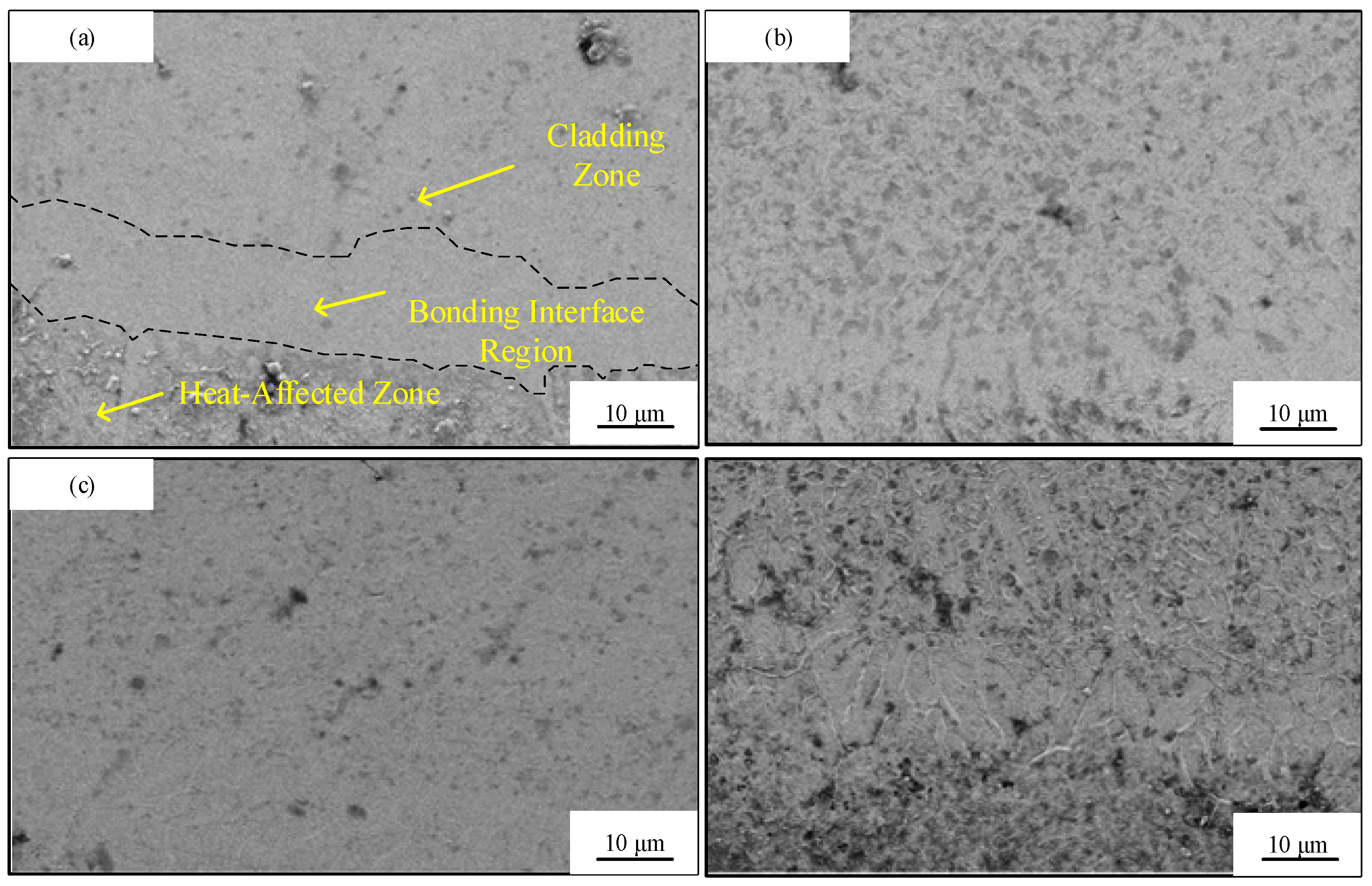
Figure 4 displays the interfacial microstructures between cladding layers and substrate materials at different scanning speeds. Microstructural analysis reveals continuous bright interdiffusion zones in all specimens (Figure 4a), suggesting effective metallurgical bonding between the substrate and cladding powder. As scanning speed increased from 120 to 480 mm/min, the interfacial morphology evolved significantly: At 120 and 240 mm/min, the coatings exhibited pronounced wide bright bands, with the clad zone microstructure dominated by coarse cellular and dendritic crystals as shown in Figure 4a,b. With increasing scanning speed, the bright bands progressively narrowed while the clad zone microstructure refined. This refinement stems from accelerated scanning rates reducing heating duration and shrinking the heat-affected zone, which concurrently lowers the melt pool’s overall temperature and thermal gradient—promoting microstructural homogeneity. The shortened melt pool dwell time also accelerates solidification kinetics, yielding predominantly fine cellular and dendritic grains. At 480 mm/min scanning speed, the melt pool exhibits the lowest thermal gradient, yielding optimal microstructural homogeneity with densely packed grains. Minimal melt pool duration produces the narrowest bright band and peak interfacial bonding strength. Accelerated solidification kinetics substantially reduce dendritic dimensions, promoting grain refinement where fine equiaxed grains dominate the clad zone. Higher scanning speeds shorten laser/material interaction time, reducing thermal input and further diminishing thermal gradients. This refines planar crystals at the interface and generates finer-grained coatings through constrained grain growth.
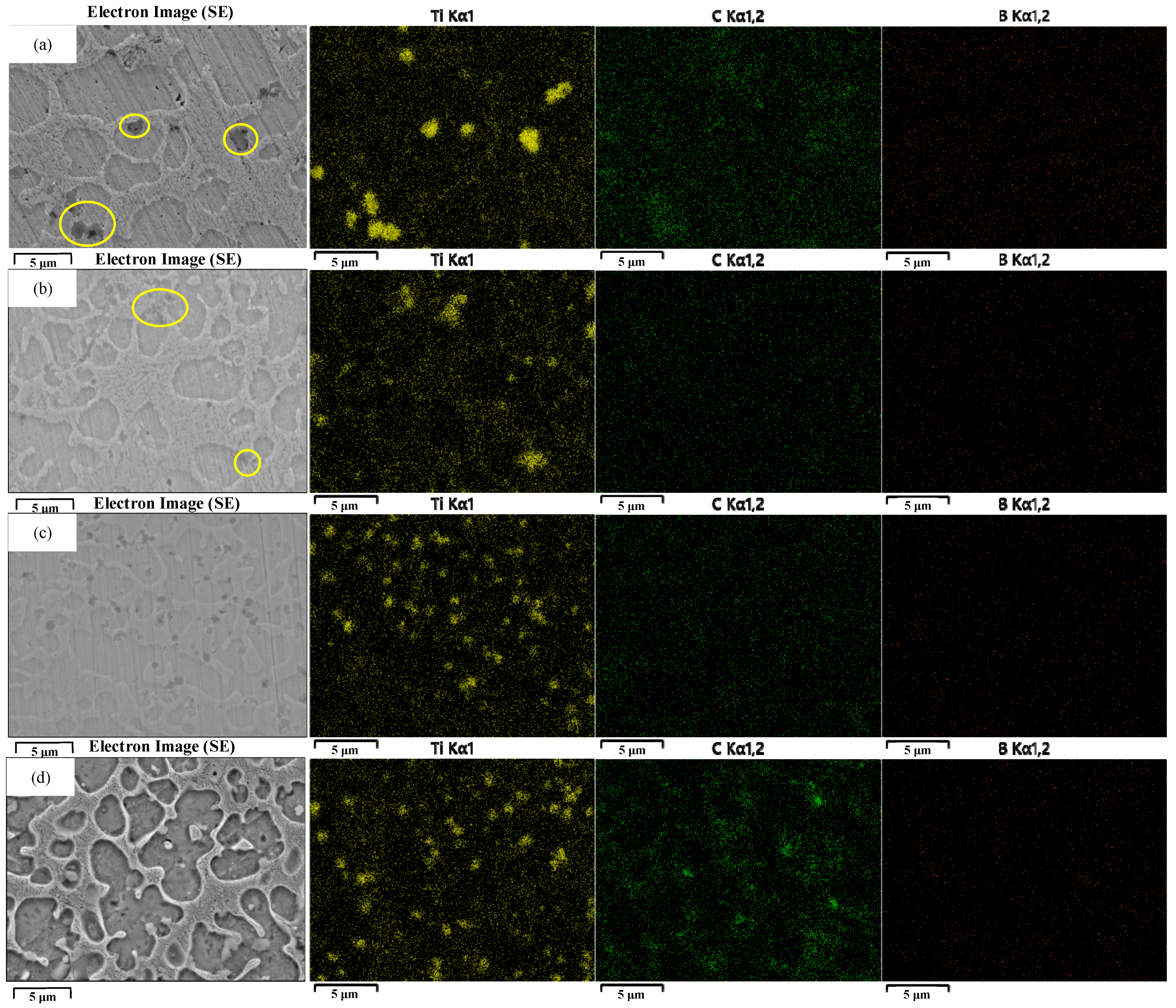
Figure 3 presents elemental mapping of clad coatings across scanning speeds. Comprehensive analysis reveals that Ni and Fe are uniformly distributed throughout the microstructure—spanning both grain boundaries and intragranular regions—exhibiting the most extensive dispersion. Conversely, Ti, C, and B elements predominantly segregate along grain boundaries, confirming preferential precipitation of ceramic reinforcements (TiC/TiB2) at these sites. This grain boundary pinning effect effectively inhibits grain growth, yielding significantly refined microstructures. At lower scanning speeds (120–240 mm/min, Figure 3a,b), however, excessive energy density and diminished cooling rates trigger multifaceted effects: grain boundary coarsening, residual stress accumulation, and ceramic particle agglomeration. These factors collectively induce microstress concentration, serving as nucleation sites for microcracks. Conversely, at enhanced scanning speeds (≥360 mm/min, Figure 3c,d), substantially improved dispersion homogeneity of reinforcements enables simultaneous dispersion strengthening and synergistic grain boundary refinement.
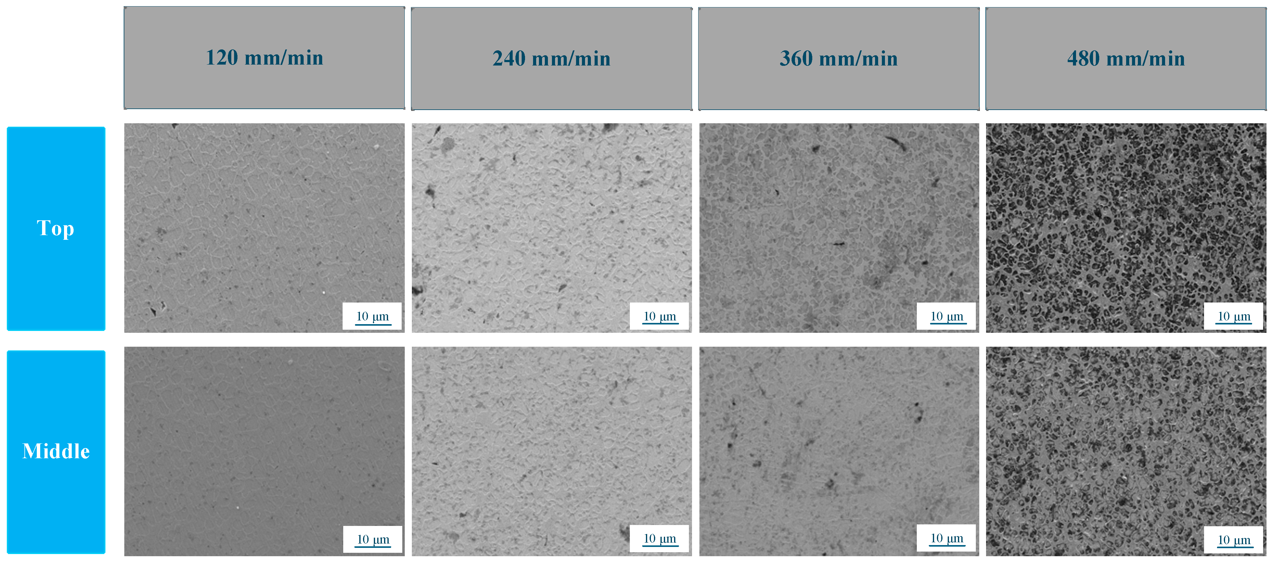
Figure 5 displays microstructures in upper and central regions of clad layer cross-sections at different scanning speeds. As revealed in Figure 4a,b, the 120 mm/min coating features coarse cellular and dendritic crystals in its upper region, while the central zone comprises mixed cellular/dendritic structures. With increasing scanning speed, the upper region develops refined cellular/dendritic grains alongside minor equiaxed crystals in lower zones. At peak speed (480 mm/min), the upper morphology transitions to predominantly fine cellular crystals with columnar dendrites and limited equiaxed grains, whereas the lower region exhibits fine cellular and equiaxed grains. At 480 mm/min scanning speed, the upper coating region exhibits a microstructure dominated by fine cellular crystals and columnar dendrites with minor equiaxed grains, while the lower region features fine cellular and equiaxed grains. Increasing scanning speed shortens laser interaction time, reducing thermal input to the coating. This accelerates melt pool cooling rates, triggering rapid solidification where accelerated dendritic growth suppresses competitive grain nucleation. Consequently, equiaxed grain density rises significantly, yielding substantial grain refinement and enhanced microstructural homogeneity. From lower to central regions of the coating, the microstructure exhibits a transition toward reduced populations of cellular and dendritic grains with a corresponding increase in equiaxed grains. Concurrently, the central zone features finer-grained morphologies than the upper region. The 45# steel substrate’s superior heat dissipation versus the melt pool creates rapid solidification in the central coating region adjacent to this cold base. This elevated cooling rate suppresses grain growth while mitigating elemental segregation and ceramic particle agglomeration, yielding refined homogeneous microstructures with uniformly dispersed strengthening phases. Conversely, prolonged thermal retention and slower cooling in the upper region promote coarser grains, elemental boundary enrichment, ceramic phase coarsening, and heightened residual stresses—collectively degrading microstructural integrity relative to the central zone. Increased scanning speeds counteract these detrimental effects by reducing thermal input and accelerating cooling, thereby enhancing overall microstructural uniformity. At 480 mm/min, the central region exhibits substantially greater equiaxed grain density than the interfacial microstructure shown in Figure 2.

3.3. Vickers Hardness of Coatings

Figure 6 presents the cross-sectional Vickers hardness profile of the laser-clad coating. Error bars represent ±1 SD. The hardness exhibits a characteristic peak-and-decline trend from the clad zone toward the substrate, with the clad region demonstrating significantly higher Vickers hardness values than adjacent zones. As scanning speed increased from 120 to 480 mm/min, the average Vickers hardness in the top clad region (≤0.2 mm from surface) rose progressively from 507 ± 8 HV0.2 to 605 ± 16 HV0.2—a 19.5% enhancement—with the 480 mm/min specimen reaching a peak hardness of 618 HV0.2. Hardness gradients decayed with depth: at 1.0 mm depth, 120 mm/min specimens decreased to 247 ± 3 HV0.2, while 480 mm/min counterparts maintained 310 ± 10 HV0.2, demonstrating improved hardness uniformity at elevated speeds. This enhancement stems from suppressed TiC/TiB2 agglomeration and dendritic coarsening at low speeds, which induce localized stress concentration and hardness degradation. Higher scanning speeds refine grains and disperse reinforcing phases, elevating overall hardness via dispersion strengthening mechanisms.
Critically, the dual-scale TiC-TiB2 reinforcement delivers substantially higher hardness enhancement than monoscale ceramics across all scanning speeds. While conventional single-phase reinforcements (e.g., TiC or TiB2) typically achieve 100–200 HV gains over pure 316L substrates [14,30], our composite coating attains +307 HV0.2 at 120 mm/min.

3.4. Tribological Properties of Coatings

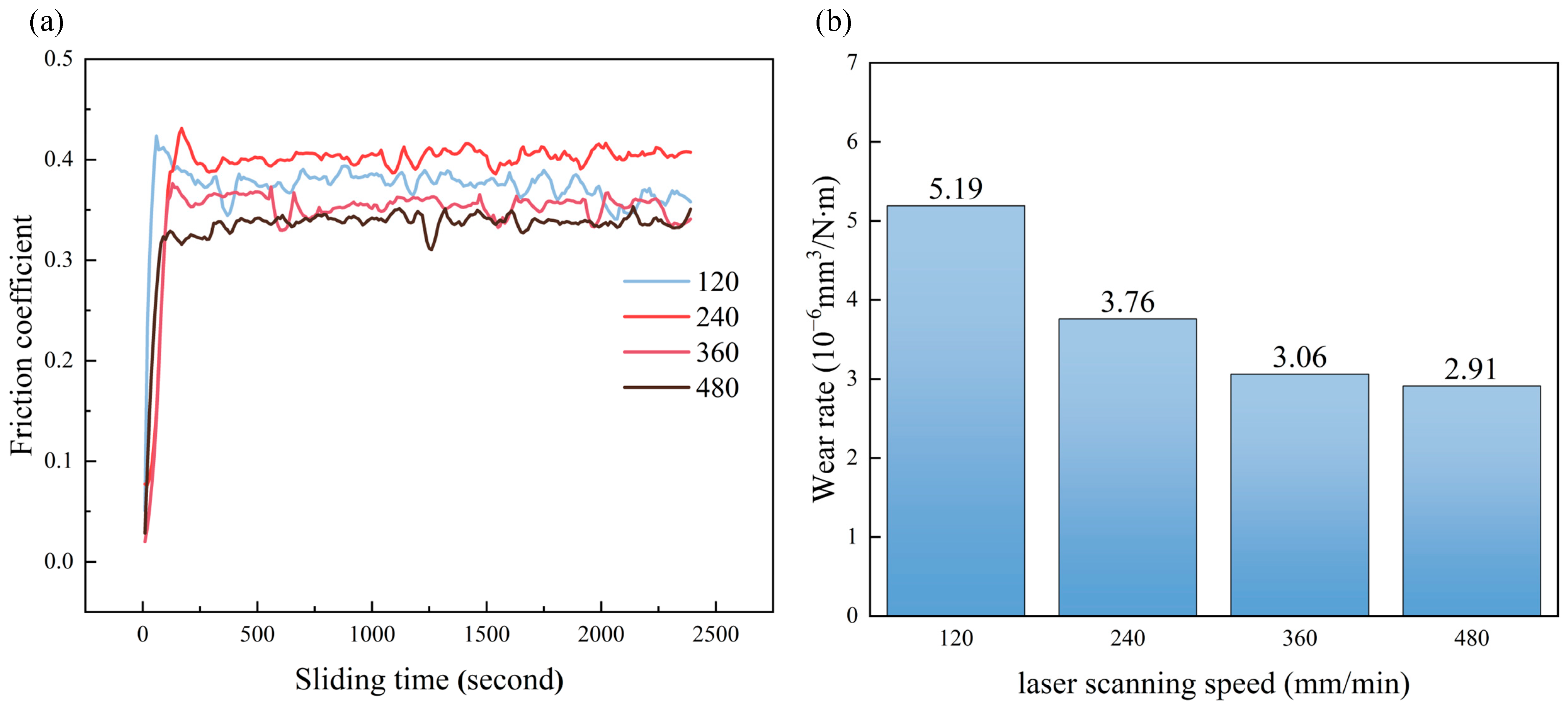
Figure 7a presents the friction coefficients of clad coatings at different scanning speeds. The 480 mm/min specimen exhibits significantly lower friction coefficients than its counterparts. Increasing scanning speed substantially reduces the friction coefficient, enhancing the coating’s anti-friction performance. This improvement is attributable to fine equiaxed grain formation and elevated Vickers hardness (605 ± 16 HV0.2) at high scanning speeds, which restricts abrasive penetration depth. From a tribological perspective, lower friction coefficients typically correlate with superior wear resistance since reduced frictional resistance minimizes surface damage.
Wear rates are presented in Figure 8b. At a constant laser power of 1200 W, with scanning speeds of 120 mm/min, 240 mm/min, 360 mm/min, and 480 mm/min, the corresponding wear rates were measured as 5.19 × 10⁻⁶ mm3/N·m, 3.76 × 10⁻⁶ mm3/N·m, 3.06 × 10⁻⁶ mm3/N·m, and 2.91 × 10⁻⁶ mm3/N·m, respectively. As the scanning speed increased, the wear rate of the samples progressively decreased, indicating enhanced wear resistance of the coating. Wear reduction can be expected as scanning speed increases, with the wear rate decreasing from 5.19 mm3/N·m (120 mm/min) to 2.91 mm3/N·m (480 mm/min). This improvement primarily arises from the progressive refinement of grains within the microstructure and the homogeneous dispersion of reinforcing phases throughout the coating. These microstructural modifications collectively elevate the coating’s Vickers hardness, mitigate abrasion by grinding particles, impede coating delamination, and ultimately enhance wear performance. Furthermore, variations in scanning speed induced a greater disparity in wear rates compared to variations in laser power. This pronounced effect is attributed to the significant grain refinement and enhanced microstructural homogeneity achieved with increasing scanning speed. These microstructural improvements substantially elevate the coating’s Vickers hardness, which in turn contributes substantially to enhanced wear resistance at the surface. Consequently, the reduction in wear rate was more pronounced across different scanning speeds.
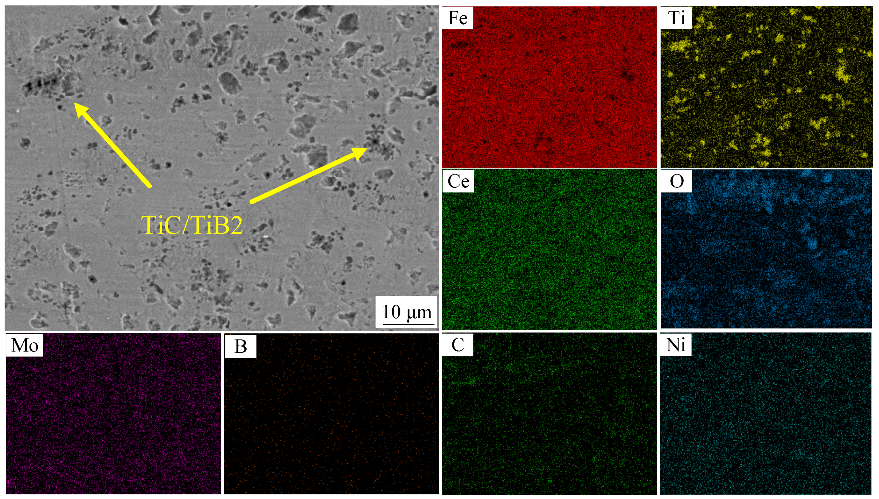
Wear morphologies of the cladding coatings produced at different scanning speeds were examined under higher magnification, as shown in Figure 8. Figure 8a presents the worn surface of the coating fabricated at 120 mm/min. Extensive spallation and pronounced plastic deformation are evident on the coating surface. The dominant wear mechanism is abrasive wear, characterized by deep grooves attributable to ploughing. This behavior stems from insufficient matrix hardness caused by coarsened dendrites, allowing TiC clusters to act as third-body abrasives that penetrate the matrix. With increasing scanning speed, the worn surfaces developed undulating textures and localized spallation pits, as depicted in Figure 8b,c. Although grain refinement enhanced the matrix’s resistance, concentrated residual stresses still triggered localized spallation. Consequently, the wear mechanism transitioned to a composite abrasive/delamination mode. At the highest scanning speed of 480 mm/min, progressive wear caused the uniformly distributed TiC/TiB2 hard phases to protrude and become exposed from the fine-grained matrix, as shown in Figure 9. These exposed particles formed surface asperities. Owing to their intrinsic ultra-high hardness, the exposed TiC/TiB2 phases acted as rigid support points, thereby reducing direct contact between the softer matrix and the counterface ball. Consequently, this led to a lower coefficient of friction (CoF), indicating an inverse correlation between hardness and the CoF [31,32,33,34]. The overall trend of the observed coefficient of friction (CoF) aligns with the hardness profile of the samples. Moreover, the spalled ceramic debris functioned as micro-abrasives, predominantly rolling at the interface rather than ploughing the matrix. This rolling action substantially reduced the material removal rate, thereby enhancing the coating’s wear resistance. Additionally, the formation of a continuous oxide layer on the coating surface indicates the occurrence of oxidative wear [35], further stabilizing the frictional behavior.
The transition in dominant wear mechanisms across scanning speeds is further elucidated by correlating friction coefficients (Figure 7a), wear rates (Figure 7b), and worn surface morphologies (Figure 8). At 120 mm/min (Figure 8a), deep parallel grooves and plastic deformation ridges confirm abrasive wear dominated by ploughing. This aligns with the high friction coefficient (0.58) and wear rate (5.19 × 10⁻⁶ mm3/N·m), attributable to insufficient matrix hardness and TiC cluster pull-out acting as third-body abrasives. At intermediate speeds (240–360 mm/min, Figure 8b,c), the emergence of undulating textures and localized spallation pits signifies a hybrid abrasive/delamination mechanism. Residual stress concentrations—despite grain refinement—initiated subsurface cracks propagating along weakened ceramic/matrix interfaces, resulting in layered material removal. Crucially, at 480 mm/min (Figure 8d), the absence of deep abrasion grooves and the formation of a continuous oxide layer (O-enrichment in Figure 9) indicate a shift to oxidative wear. Here, uniformly dispersed TiC/TiB2 hard phases protruded as asperities, reducing direct matrix/counterface contact while stabilizing friction (CoF: 0.34). Spalled ceramic debris primarily rolled rather than ploughed the surface, synergized with the oxide layer’s lubricating effect to minimize wear rate (2.91 × 10⁻⁶ mm3/N·m).

4. Conclusions

This study successfully fabricated TiC-TiB2 dual-scale ceramic particle-reinforced 316L stainless steel composite coatings on 45 steel substrates using laser cladding technology. The influence of scanning speed (120–480 mm/min) on the coating’s microstructural evolution, mechanical properties, and wear behavior was systematically investigated. The principal findings are summarized as follows:
(1)
Increased scanning speed induced a microstructural transition from cellular dendrites to equiaxed grains, concurrently enhancing the distribution homogeneity of the dual-scale ceramic particles. This refinement is attributed to rapid cooling, which promotes fine-grain strengthening alongside dispersion strengthening effects.
(2)
At the optimal scanning speed of 480 mm/min, the coating achieved a peak surface hardness of 618.4 HV0.2, representing a 22.0% enhancement over the value of 507 HV0.2 obtained at 120 mm/min. Concurrently, the coefficient of friction (COF) can be expected to decrease with increasing scanning speed, while the wear rate may decline significantly from 5.19 × 10⁻⁶ mm3/N·m to 2.91 × 10⁻⁶ mm3/N·m—a 58.6% reduction. This substantial decrease in wear rate corresponds to a transition in the dominant wear mechanism: from abrasive ploughing in coarse-grained regions to oxidative wear coupled with an asperity barrier effect within the refined microstructure.
The novelty of this work lies in pioneering dual-scale hybrid reinforcement to overcome conventional strength/ductility trade-offs in stainless steel coatings. This strategy provides two key advances: it identifies scanning speed as a cost-effective dominant parameter for industrial applications (e.g., bearings and shafts) and establishes a microstructure property linkage where rapid solidification governs tribo-oxidation behavior.

Author Contributions

Conceptualization, J.J. and D.Z.; investigation, D.Z. and Z.Z.; resources, D.Z. and Y.L.; data curation, Z.Z. and J.J.; writing—original draft preparation, J.J.; Z.Z. and D.Z.; supervision, Z.Z. and H.L.; funding, Y.L. All authors have read and agreed to the published version of the manuscript.

Funding

This study was supported by the Education Department of Jilin Province within the scope of the project numbered (JJKH20250860KJ), the Jiujiang Key Research and Development Program (2025_001106) 2024 Key Research Platforms and Projects for Universities in Guangdong Province (2024KCXTD073), 2024 University Research Project of Guangzhou Education Bureau (2024312005).

Data Availability Statement

Data are contained within the article.

Acknowledgments

We would like to acknowledge the financial support from the Education Department of Jilin Province (JJKH20250860KJ), the Jiujiang Key Research and Development Program (2025_001106), 2024 Key Research Platforms and Projects for Universities in Guangdong Province (2024KCXTD073), 2024 University Research Project of Guangzhou Education Bureau (2024312005).

Conflicts of Interest

The authors declare no conflict of interest.

References

  1. Liang, Q.; Xu, Y.; Xu, B.; Chen, H.; Ma, B. Effect of in-situ synthesis of TiC/TiB2 particles by laser cladding on the microstructure and properties of Co-based coatings. Opt. Laser Technol. 2025, 192, 113620. [Google Scholar] [CrossRef]
  2. Mojaddarasil, M.; Tavakoli, M.R. Investigation of Polyamide 12 Powder Cooling Process Under Natural Convection via Porous Medium, Non-Porous Medium, and Experimental Approaches. J. Mater. Eng. Perform. 2025, 34, 9352–9373. [Google Scholar] [CrossRef]
  3. Mojaddarasil, M.; Kiani, A.; Tavakoli, M.R.; Badrossamay, M. A Parametric Study of Powder Bed Temperature Distribution in Selective Laser Sintering Process. J. Mater. Eng. Perform. 2023, 32, 3348–3367. [Google Scholar] [CrossRef]
  4. Ding, T.; Li, C.; Jing, W.; Di, X.; Hu, W. Influences of boron on the microstructural characteristics and wear performance of hypereutectic Fe-Cr-C-Mo-xB hardfacing alloy. Surf. Coat. Technol. 2024, 478, 130415. [Google Scholar] [CrossRef]
  5. Tao, J.; Dong, L.; Wu, Y.; Liu, X.; Xie, J.; Wu, H.; Ran, Q. Fabrication of room temperature self-healing, robust superhydrophobic coatings via spraying dual cross-linking supramolecular silicone polymer/SiO2 composite. Compos. Part B Eng. 2024, 273, 111245. [Google Scholar] [CrossRef]
  6. Yang, L.; Zhou, Z.; Feng, S.; Wang, J.; Chen, M.; Qiao, Y.; Zhu, S.; Wang, F. Oxidation behavior of NiCrAlY coatings with man-made IDZ fabricated by arc ion plating at 1050 °C. Surf. Coat. Technol. 2024, 478, 130426. [Google Scholar] [CrossRef]
  7. Narayanan, C.U.; Daniel, A.; Praveenkumar, K.; Manivasagam, G.; Suwas, S.; Prashanth, K.; Anand, P.S.P. Effect of scanning speed on mechanical, corrosion, and fretting-tribocorrosion behavior of austenitic 316L stainless steel produced by laser powder bed fusion process. J. Manuf. Process. 2024, 131, 1582–1593. [Google Scholar] [CrossRef]
  8. Wang, Z.; Liu, H.; Huang, J.; Zhuo, S.; Wu, Y.; Wang, G.; Zheng, Z.; Qiu, Z.; Zeng, D. Improving wear and corrosion resistance of HVAF sprayed 316L stainless steel coating by adding TiB2 ceramic particles and CeO2. J. Mater. Res. Technol. 2024, 31, 1313–1325. [Google Scholar] [CrossRef]
  9. Weng, F.; Yu, H.; Chen, C.; Liu, J.; Zhao, L. Microstructures and properties of TiN reinforced Co-based composite coatings modified with Y2O3 by laser cladding on Ti–6Al–4V alloy. J. Alloys Compd. 2015, 650, 178–184. [Google Scholar] [CrossRef]
  10. Zhang, L.; Zhao, Z.; Bai, P.; Du, W.; Li, Y.; Yang, X.; Wang, Q. Corrigendum to “In-situ synthesis of TiC/graphene/Ti6Al4V composite coating by laser cladding” [Mater. Lett. 270 (2020) 127711]. Mater. Lett. 2020, 271, 127787. [Google Scholar] [CrossRef]
  11. Dong, H.; Chai, L.; Wang, C.; Liu, H.; Hu, C.; Zhao, X.; Yang, Y.; Zhang, M. TiO2 addition induced grain refinement and hardening of laser-clad FeCrAl coating on T91 steel. Mater. Charact. 2025, 225, 115194. [Google Scholar] [CrossRef]
  12. Tiwari, V.; Mandal, V.; Sarkar, M.; Kumar, A.; Bhagyaraj, J.; Singh, M.K.; Mukherjee, S.; Mondal, K.; Ramkumar, J.; Jain, J.; et al. Enhanced mechanical properties and microstructure of TiC reinforced Stellite 6 metal matrix composites (MMCs) via laser cladding additive manufacturing. J. Alloys Compd. 2025, 1010, 178001. [Google Scholar] [CrossRef]
  13. Li, N.; He, D.; Liu, D.; Ma, L.; He, C.; Xu, Y.; Yu, J. In-situ TiB reinforced titanium matrix composite coatings prepared by laser cladding: Effect of TiB2 content on microstructure, hardness and wear properties. J. Alloys Compd. 2025, 1010, 178215. [Google Scholar] [CrossRef]
  14. Liu, Y.; Chen, H.; Han, R.; Peng, Y.; Wang, K.; Li, X. Investigating the microstructure and mechanical properties of 316L/TiB2 composites fabricated by laser cladding additive manufacturing. J. Mater. Res. Technol. 2024, 29, 28–39. [Google Scholar] [CrossRef]
  15. Yang, L.; Yu, T.; Li, M.; Zhao, Y.; Sun, J. Microstructure and wear resistance of in-situ synthesized Ti(C, N) ceramic reinforced Fe-based coating by laser cladding. Ceram. Int. 2018, 44, 22538–22548. [Google Scholar] [CrossRef]
  16. Sun, X.; Li, F.; Li, Y.; Du, J.; Qi, X.; Cui, W.; Niu, J. Enhancing the wear and high-temperature oxidation behavior of NiCrBSi coatings by collaboratively adding WC and Cr3C2. Surf. Coat. Technol. 2023, 473, 129968. [Google Scholar] [CrossRef]
  17. Zeinali Moghaddam, H.; Sharifitabar, M.; Roudini, G. Microstructure and wear properties of Fe–TiC composite coatings produced by submerged arc cladding process using ferroalloy powder mixtures. Surf. Coat. Technol. 2019, 361, 91–101. [Google Scholar] [CrossRef]
  18. Lin, Y.; Jiang, C.; Lin, Z.; Chen, Q.; Lei, Y.; Fu, H. Laser in-situ synthesis of high aspect ratio TiB fiber bundle reinforced titanium matrix composite coating. Opt. Laser Technol. 2019, 115, 364–373. [Google Scholar] [CrossRef]
  19. Lo, K.H.; Cheng, F.T.; Kwok, C.T.; Man, H.C. Improvement of cavitation erosion resistance of AISI 316 stainless steel by laser surface alloying using fine WC powder. Surf. Coat. Technol. 2003, 165, 258–267. [Google Scholar] [CrossRef]
  20. Zheng, Y.; Lian, G.; Lu, H.; Chen, C.; Huang, X. Defects, organization, and properties of TiB2–TiC Bi-ceramic phase by laser cladding in situ synthesis. Ceram. Int. 2024, 50, 41097–41116. [Google Scholar] [CrossRef]
  21. Liu, Z.; Wu, S.; Liu, W.; Wu, Y.; Liang, X. Optimization of multiple responses in the laser cladding process parameters. Mater. Manuf. Process. 2024, 39, 2139–2153. [Google Scholar] [CrossRef]
  22. Chen, C.; Huang, B.; Liu, Z.; Chen, L.; Li, Y.; Zou, D.; Chang, Y.; Cheng, X.; Zhou, R.; Liu, Y. Material extrusion additive manufacturing of WC-9Co cemented carbide. Addit. Manuf. 2024, 86, 104203. [Google Scholar] [CrossRef]
  23. Dai, X.; Wu, Q.; Li, X.; Wang, X.; Shi, Y.; Zhou, Y.; Wen, S.; Shi, Y. Crack suppression and ductility modification of additive manufactured Ti6Al4V/W heterostructure interface via Nano-TiC reinforcement. Eng. Fail. Anal. 2025, 180, 109852. [Google Scholar] [CrossRef]
  24. Feng, Z.; Tan, H.; Fang, Y.; Lin, X.; Huang, W. Selective laser melting of TiB2/AlSi10Mg composite: Processability, microstructure and fracture behavior. J. Mater. Process. Technol. 2022, 299, 117386. [Google Scholar] [CrossRef]
  25. Zheng, Y.; Wang, Y.; Li, B.; Bai, Y.; Xu, H.; Liu, L.; Song, B.; Li, X. High cooling rate solidification: Promoting uniform distribution of nano TiB2-TiC particles and enhancing the high-temperature mechanical properties of Al5Cu alloy. Mater. Charact. 2025, 225, 115182. [Google Scholar] [CrossRef]
  26. ASTM E407–07; Standard Practice for Microetching Metals and Alloys. ASTM International: West Conshohocken, PA, USA, 2015.
  27. Bhavan, J.S.; Amer, M.; Unnikrishnan, T.G. In situ X-ray Diffraction investigation of Graphene-Enhanced Sn-Ag solder Alloys: Insights into phase transformations. Mater. Sci. Eng. B 2025, 321, 118492. [Google Scholar] [CrossRef]
  28. Disha, S.A.; Sahadat Hossain, M.; Habib, M.L.; Ahmed, S. Calculation of crystallite sizes of pure and metals doped hydroxyapatite engaging Scherrer method, Halder-Wagner method, Williamson-Hall model, and size-strain plot. Results Mater. 2024, 21, 100496. [Google Scholar] [CrossRef]
  29. Zenou, V.Y.; Bakardjieva, S. Microstructural analysis of undoped and moderately Sc-doped TiO2 anatase nanoparticles using Scherrer equation and Debye function analysis. Mater. Charact. 2018, 144, 287–296. [Google Scholar] [CrossRef]
  30. Ertugrul, O.; Enrici, T.M.; Paydas, H.; Saggionetto, E.; Boschini, F.; Mertens, A. Laser cladding of TiC reinforced 316L stainless steel composites: Feedstock powder preparation and microstructural evaluation. Powder Technol. 2020, 375, 384–396. [Google Scholar] [CrossRef]
  31. Pamuk, U.; Baydoğan, M.; Nilüfer, B.; Çimenoğlu, H. An energetic approach to abrasive wear of a martensitic stainless steel. Scr. Mater. 2000, 42, 881–885. [Google Scholar] [CrossRef]
  32. AlMangour, B.; Grzesiak, D.; Yang, J.-M. Rapid fabrication of bulk-form TiB2/316L stainless steel nanocomposites with novel reinforcement architecture and improved performance by selective laser melting. J. Alloys Compd. 2016, 680, 480–493. [Google Scholar] [CrossRef]
  33. Sinha, S.K.; Reddy, S.U.; Gupta, M. Scratch hardness and mechanical property correlation for Mg/SiC and Mg/SiC/Ti metal–matrix composites. Tribol. Int. 2006, 39, 184–189. [Google Scholar] [CrossRef]
  34. Xu, X.; van der Zwaag, S.; Xu, W. The scratch and abrasive wear behaviour of a tempered martensitic construction steel and its dual phase variants. Wear 2016, 358–359, 80–88. [Google Scholar] [CrossRef]
  35. Ralls, A.M.; Leong, K.; Liu, S.; Wang, X.; Jiang, Y.; Menezes, P.L. Unraveling the friction and wear mechanisms of surface nanostructured stainless-steel. Wear 2024, 538–539, 205185. [Google Scholar] [CrossRef]
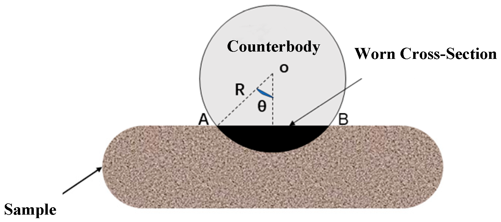
Figure 1. Schematic of wear volume calculation.
Lubricants 13 00359 g001
Figure 2. XRD patterns of composite coatings fabricated at different laser scanning velocities: (a) 120 mm/min; (b) 240 mm/min; (c) 360 mm/min; (d) 480 mm/min.
Lubricants 13 00359 g002
Figure 3. Elemental mapping of selected regions in cladding coatings fabricated at different laser scanning velocities: (a) 120 mm/min; (b) 240 mm/min; (c) 360 mm/min; (d) 480 mm/min.
Lubricants 13 00359 g003
Figure 4. Microstructure at the bonding interface of cladding coatings and substrate fabricated at different laser scanning velocities: (a) 120 mm/min; (b) 240 mm/min; (c) 360 mm/min; (d) 480 mm/min.
Lubricants 13 00359 g004
Figure 5. Microstructure of composite coatings fabricated at different laser scanning velocities.
Lubricants 13 00359 g005
Figure 6. Cross-sectional Vickers hardness of cladding coatings fabricated at different laser scanning velocities.
Lubricants 13 00359 g006
Figure 7. (a) Friction coefficient and wear rate of cladding coatings fabricated at different laser scanning velocities; (b) wear rate of cladding coatings fabricated at different laser scanning velocities.
Lubricants 13 00359 g007
Figure 8. Wear track morphology of cladding coatings fabricated at different laser scanning velocities: (a) 120 mm/min; (b) 240 mm/min; (c) 360 mm/min; (d) 480 mm/min.
Lubricants 13 00359 g008
Figure 9. Elemental mapping of wear tracks in cladding coatings fabricated at 480 mm/min scanning velocity.
Lubricants 13 00359 g009
Table 1. Chemical composition of Grade 45 steel.
ElementCSiMnNiCrCuFe
Wt. %0.42~0.500.17~0.370.50~0.80≤0.30≤0.25≤0.25balance
Table 2. Experimental materials.
MaterialsAverage Particle SizePurity (%)
316L48 μm≥99.0%
TiB21 μm≥99.0%
TiC50 nm≥99.5%
Table 3. Chemical compositions of 316 powder and 316 substrate.
ElementCrSiBCFeNi
wt. %14~173~4.52.5~4.50.6~1.0≤15balance
Disclaimer/Publisher’s Note: The statements, opinions and data contained in all publications are solely those of the individual author(s) and contributor(s) and not of MDPI and/or the editor(s). MDPI and/or the editor(s) disclaim responsibility for any injury to people or property resulting from any ideas, methods, instructions or products referred to in the content.