1. Introduction
Aerostatic thrust bearings, which represent the focal point of this work, are a type of HS (hydrostatic) bearing characterized by their ability to support axial loads by maintaining a thin, pressurized film of gas (air) between the mating surfaces. This film is generated using a supply system providing pressurized air, which, in turn, is further distributed through flow control devices (also known as restrictors). Amongst their main advantages, one can mention low friction, zero mechanical wear due to the absence of contact, high stiffness, and clean operation due to the absence of typical oil lubrication. These characteristics make them particularly suitable for high-precision machinery and applications where contamination or vibration must be minimized. A wide array of industries, from computing and telecommunications to aerospace and biomedicine, rely on the use of air bearings.
Advanced motion control systems, such as multi-axis CNC (Computer Numerical Control) machinery or coordinate measuring machines (CMMs), benefit from air bearings due to their ability to accommodate a range of loads while maintaining nanometric accuracy and minimizing trajectory deviations [
1]. Air bearings are also important in various manufacturing processes such as drilling at micro- and nanoscales, where both precision and high quality are paramount [
2]. Another notable application involves handling sensitive components in non-contact environments. For example, air bearings are advantageous in the fabrication of liquid crystal displays (LCDs), where delicate parts must be manipulated without physical contact [
3]. Furthermore, the aerospace sector remains a prominent user and developer of air-bearing technology. In free-floating, low-gravity environments—such as autonomous satellites equipped with robotic arms (i.e., space manipulators)—the frictionless motion of air bearings is essential to minimize disturbances and achieve ultra-precise positioning [
4,
5].
Interest in the subject has been constantly demonstrated by the numerous review articles published throughout the years. These studies have explored different types of air bearings and restrictor systems, each serving unique purposes and solving distinct engineering challenges. According to Gross [
6], the fundamentals of gas bearing technology were understood by the end of the 1950s. His review, published in 1969, includes a summary of the first decade of modern gas bearing development, and proposes a classification of structural configurations, focusing on flow control methods using restrictors. The presentation is mostly dedicated to radial bearings.
Another notable review carried out around the same period is that of Munday [
7,
8], who offers a detailed classification and description of restrictor designs, accompanied by a comprehensive table containing the calculation methods available at the time. Majumdar (1980) [
9] compiled over 80 articles and patents from the golden era of gas lubrication (1960–1980). Later, Lentini et al. [
10] reviewed over a century of gas bearing development, focusing on compensation methods and the evolution of design approaches.
The interest for this subject was also highlighted in the recent works of both Gao et al. [
11] and Zhao et al. [
12], which provide comprehensive state-of-the-art reviews covering a wide period, analyzing recent advances such as static and dynamic characteristic, pneumatic hammer effect, air-induced vibration and stability, wall slip effects, multiphysics modelling, and modern experimental techniques. Together, these reviews illustrate the evolving landscape of air bearing research and their indispensable role in cutting-edge precision engineering, and draw future research directions and development trends in the coming decade and beyond
One should note that the bearing itself is not the main actor but rather the restrictor, which controls the air supply in order to maintain the film between surfaces and prevents them from getting in contact. Restrictors in aerostatic bearings may be passive or active. Passive restrictors are simpler and more robust, while active restrictors offer improved dynamic performance through electronic control systems. Passive restrictors are further classified by air supply method: discrete supply (one or more orifices, with or without recesses or grooves) and distributed supply (porous media). Porous restrictors are usually made of sintered carbon [
13,
14] or similar materials and allow continuous, fine air control.
One of the objectives of the design of air bearings is to achieve the so-called infinite stiffness, a characteristic which, in general, cannot be obtained with passive compensation [
15]. However, some design solutions, which include compliant components (deformable bearing surface [
16,
17,
18] or deformable diaphragm regulating valve [
19,
20,
21]), can provide infinite stiffness over a large range of bearing loading.
The present work proposes a new concept for a variable resistance restrictor, based on a porous layer, which provides, in certain circumstances, infinite stiffness. In contrast with classical porous restrictors, which are practically rigid, our concept solution proposes a soft, highly compressible porous layer. Its thickness varies with the pressure difference between the supply and the recess pressure. As a result, its porosity and the corresponding permeability adjust continuously, controlling the flowrate, function of the bearing load.
The solution was inspired by the squeeze effect of imbibed porous layers used to enhance lifting force generation, damping, and shock absorption; a concept sometimes called eX-Poro-HydroDynamic (XPHD) lubrication mechanism. Originally introduced by M.D. Pascovici for liquids [
22] and independently developed by Prof. Weinbaum’s research group [
23], as well as by R. Crawford et al. [
24] and Zhu et al. [
25] for gases, this concept relies on highly porous, soft layers that expel fluid under compression. When the material is compressed, its permeability decreases progressively, resulting in greater flow resistance and reduced flowrate.
The objective of this research is to introduce and validate theoretically the novel design solution of a porous, compliant restrictor used in a full circular, aerostatic thrust bearing. A simplified analytical model evaluates load capacity, flowrate, and stiffness, while a parametric analysis defines optimal restrictor properties and performance limits.
The advantage of using analytical models is that they offer a more accessible and cost-effective alternative than numerical solutions (which require access to specialized software or programming tools), providing quick results with basic computational tools (such as Excel), without the need for expensive licenses. Such solutions are especially valuable in the early design stages, allowing quick adjustments without the time-consuming remeshing required in numerical methods.
Results show that the design achieves near-infinite stiffness, making it suitable for advanced applications.
2. The Model
The novel concept of a poro-elastic restrictor is examined for the following configuration: a single-recess, circular-pad thrust bearing that serves as the building block for more complex designs.
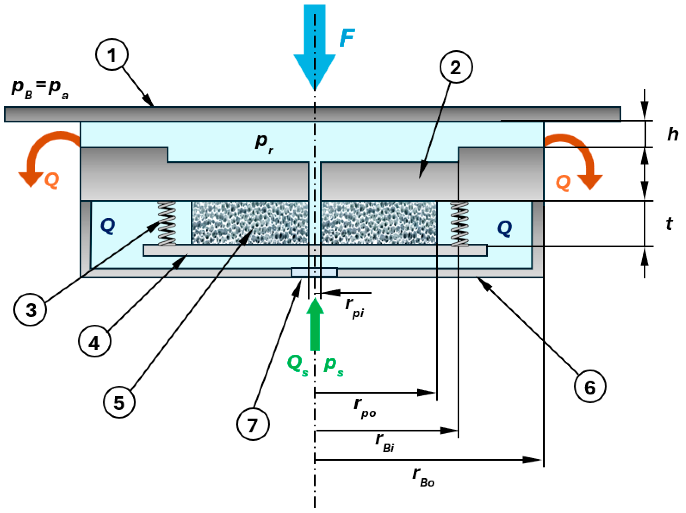
Figure 1 schematically illustrates the bearing and restrictor arrangement. The circular recess of the bearing pad is supplied with air maintained at an absolute pressure,
pr through a relatively large supply orifice, which allows pressure variations through it to be neglected.
The flowrate of the supplied air is controlled through an annular porous disc, initially possessing a porosity ε0. It is housed in a pressurized chamber at the pressure ps. A rigid, thin pressure plate supports the porous disc and varies its effective thickness in response to the combined action of the supply pressure ps and the pressure distribution within the porous material. Herein, the pressure of the air inside the disc drops from the supply pressure ps down to the recess pressure pr. Consequently, the disc’s porosity, and hence its permeability, are self-regulated by the bearing load. Air flows radially through the porous disc at a flowrate dictated by this permeability. One or more springs positioned between the lower bearing pad and the pressure plate help adjust the plate’s position, ensuring the elasticity and symmetry requirements are met.
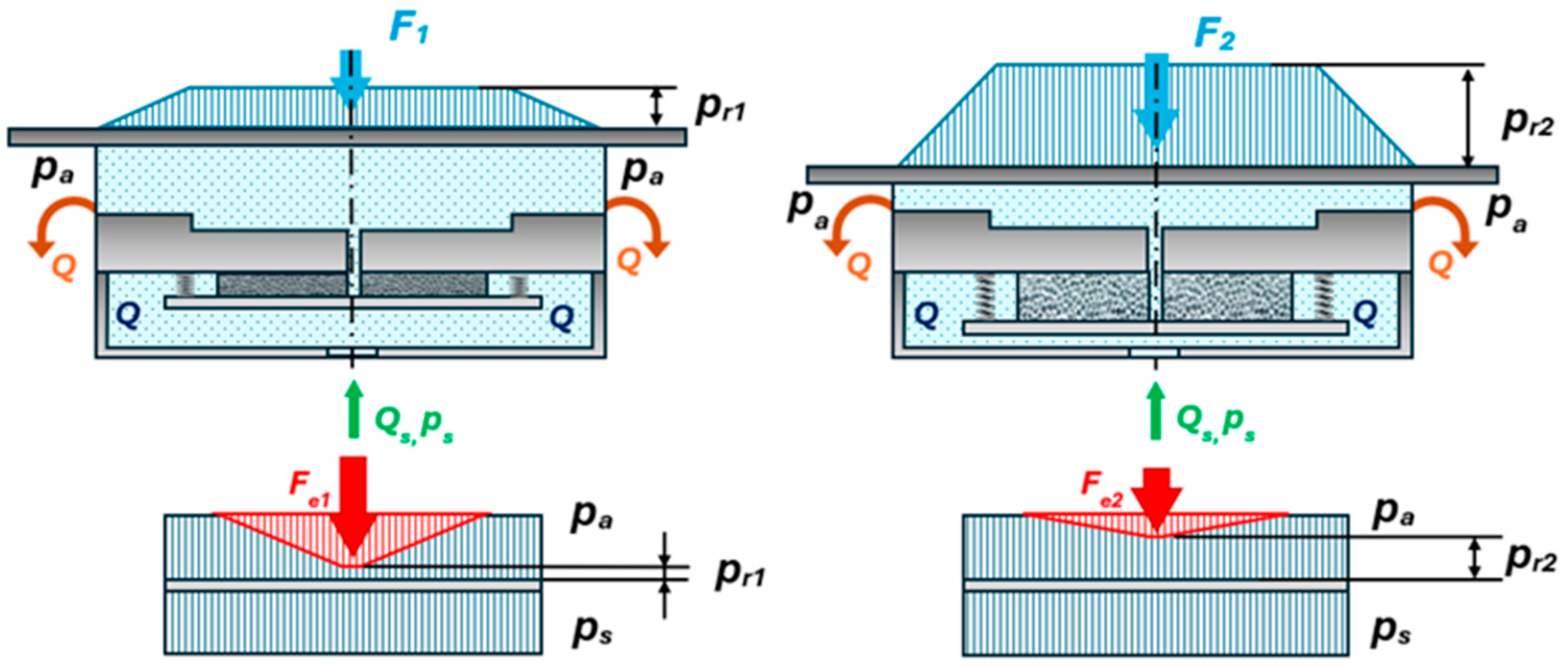
The principle of operation relies on the correlation between the bearing load and porous disc thickness, and it is schematically presented in
Figure 2. When the load on the bearing is low, the pressure plate is subjected to a greater pressure differential, and the porous disc is compressed; consequently, the porosity, the permeability, and the flowrate are small. When a higher load is applied on the bearing, the pressure distribution increases on the porous disc side, leading to its compression; consequently, the porosity, as well as the permeability, increase, resulting in an increased flowrate, which keeps an almost constant film thickness.
Since the current work represents a first attempt to present the proposed innovative device, the objective is to obtain a better understanding of the phenomena involved in its operation. Due to the complexity of the problem, several simplifying assumptions must be introduced in order to perform the analysis:
Steady state conditions prevail, due to the constant in time and isothermal operation of the bearing.
Self-lubricating effects, as well as squeeze effects, are negligible because both pads are stationary. Thus, purely aerostatic effects are considered.
The fluid is an ideal gas, with a laminar flow pattern and constant properties across the bearing gap.
The bearing pads are aligned (their two surfaces are parallel and concentric); thus, the analysis is conducted axisymmetrically. Hence, the flow in the bearing gap is one-dimensional, and the gap thickness is constant.
The pressure in the bearing recess pr is constant, and the recess has a small depth to avoid pneumatic instability and shockwaves.
Because the orifice is quite large, the pressure drop between the porous restrictor and the bearing recess is neglected. Therefore, the pressure at the inner diameter of the porous disc is equal with the pressure in the recess.
The flow is isothermal, implying constant viscosity throughout the system.
The air flow inside the porous disc is assumed in-plane, Darcyan, axisymmetrically (one-dimensional, inwardly); this is justified by its small thickness-to-radius ratio.
The Kozeny–Carman relationship is utilized for the permeability–porosity correlation, emphasizing the interaction between these properties in porous media [
26].
Here, is a dimensional constant (expressed in m2), which is determined through experiments and can be related to the dimensional characteristic of the porous structure (e.g., pore diameter or fiber diameter).
The conservation of the solid phase in the porous matrix is assumed, acknowledging that the cross-section area remains constant throughout the analysis (there is no transverse deformation during compression) [
22]. Accordingly:
Starting from Reynolds’ equation for an axisymmetric, steady-state, laminar, and isothermal flow of a compressible fluid,
and its corresponding boundary conditions:
we obtain by integration the radial pressure distribution on the lower pad [
27]:
For the sake of simplicity, the pressure drop on the lower pad will be considered linear for bearing load calculation. Even if this assumption could be argued, it will simplify the equations without affecting the principle of flow regulation. Thus, the following equation is obtained:
By considering the following load non-dimensionalization:
Equation (5) can be written in dimensionless form as follows:
where
is the recess-ambient pressure ratio and
is the bearing size ratio.
Equation (7) can be further simplified by introducing the bearing size parameter
, leading to a more compact form:
Unlike the pressure distribution, the mass flowrate will be kept in its real, logarithmic form. On the land, the mass flowrate corresponding to a uniform film thickness,
h, is [
27]:
where
and
are the ambient air density and pressure,
is the viscosity, and
is an arbitrary value that does not influence the results.
Using the following flowrate non-dimensionalization:
the mass flowrate on the bearing pad
becomes
where
is the dimensionless film thickness, with
being a constant, arbitrary value that does not affect the results.
On the other hand, the flow through the porous disc is governed by Darcy’s law [
14]:
while the mass flowrate through the porous disc will be
The permeability
from Equation (12) can be written with respect to the disc thickness by combining Equations (1) and (2):
where
is the compression rate.
Equation (13) can be rewritten using the same nondimensionalizing form as Equations (10) and (14), as follows:
where
, is the permeability parameter,
is the supply-ambient pressure ratio,
is the porous disc size ratio, and
is the porous disc relative radius.
The thickness of the porous disc, t, can be obtained after considering the static equilibrium of the pressure plate, which is subjected to pressure forces and the spring elastic force:
Closing force produced by the supply pressure on one side of the plate and by the pressure distribution in the porous disc, which varies from
ps, at the outer diameter, to
pr at the inner diameter (equal to the bearing supply orifice), on the other side (as seen in
Figure 2):
which, when employing Equation (6), becomes in dimensionless form:
The opening elastic force, generated by the spring, neglecting spring preload:
which, similarly to Equation (17), becomes in dimensionless form:
The static equilibrium of the pressure plate, defined by Equations (17) and (19), gives the relationship between the pressure in the recess and the thickness of the porous disc, in dimensionless form:
which further translates into
where
represents the porous disc size parameter, and
the spring stiffness parameter.
According to the dimensionless flowrate conservation,
, Equations (11) and (15) can be written after several algebraic manipulations as follows:
The resulting equation gives the main solution of the analysis, which is the relation between the dimensionless film thickness and the dimensionless load on the bearing:
where
is the flowrate parameter.
In order to calculate static stiffness, Equation (23) was integrated, resulting in
3. Parametric Analysis
Equation (23) includes seven non-dimensional parameters: three size parameters collected under the symbol R (all sub-unitary because each is defined as the ratio of the smaller radius to the larger one), three complex functional parameters (K, ε0, λ) related to the restrictor elasticity and material, and one supply pressure parameter, γ.
The first objective of the analysis is to determine the influence of the dimensionless parameters specific to the porous disc on the static performance of the bearing. Following the analytical model, four important parameters were identified—the spring stiffness parameter K, the permeability parameter λ, the initial porosity ε0, and the porous disc relative radius RPB. They were chosen because these are the parameters strictly connected to the porous disc.
Since the ranges of possible values for K, ε0, λ, and RPB are wide, a complete multi-dimensional analysis would be challenging from a computational point of view; instead, each plot varies one parameter at a time while keeping all others fixed so that its individual influence stands out. For every case, three response functions are reported: the dimensionless bearing load vs. film thickness characteristic, the dimensionless (static) stiffness vs. bearing load characteristic, and the dimensionless mass flowrate vs. film thickness characteristic.
The second objective is the comparison of the performances of the bearing with the proposed porous restrictor against a conventional restrictor, a pocketed orifice. The mass flowrate through the orifice is given by [
27] as follows:
where
for isothermal flow.
Same as before, the mass flow conservation gives the main relationship between load and film thickness in dimensionless form:
where
is the dimensionless discharge parameter.
Here, the discharge coefficient of the orifice was considered constant, with a frequently used value of
[
28] and another common value for the orifice radius
[
29]. The orifice parameters were chosen so that, for an approximate average value of the dimensionless bearing load of
, there is a point of intersection between the dimensionless bearing load-film thickness characteristic curve of the orifice and the one for the proposed porous restrictor, where all the considered cases have roughly the same film thickness. This reference point facilitates the comparison between the two types of restrictors.
The analysis was performed assuming a constant supply pressure of
for both bearings, a reference film thickness
, and a constant initial disc thickness
, which appears in the calculation of the spring stiffness parameter
K and the permeability parameter
λ. The size parameters were kept constant throughout the analysis, assuming a frequently used value for the bearing size ratio
RPB, and reasonable, arbitrary values for the other size parameters, as shown in
Table 1:
In a first instance, the parameter describing the elasticity of the spring is varied.
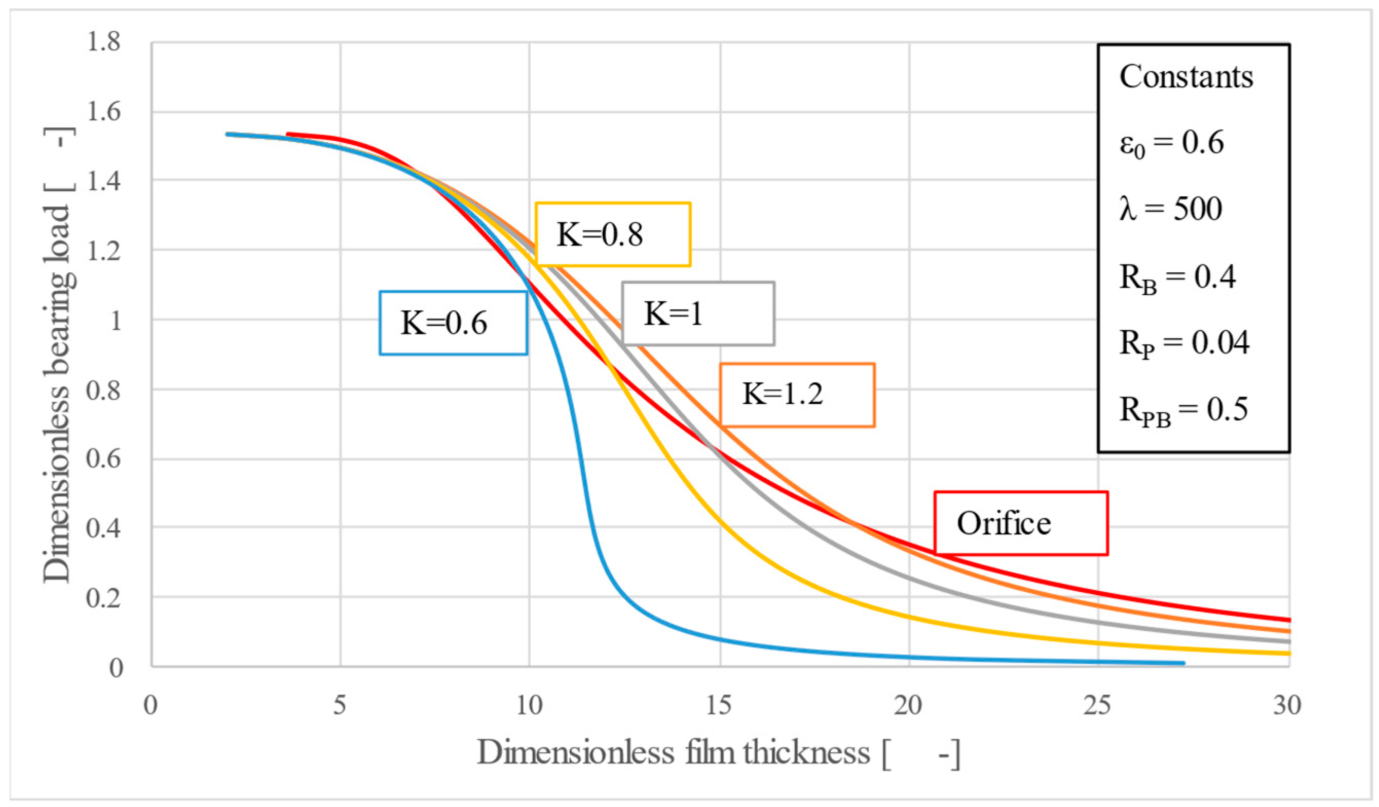
Figure 3 shows that adjusting the spring stiffness parameter
K—controlled through the spring stiffness
k (for example,
K = 0.6 corresponds to
k = 95 N mm
−1,
,
,
rBo = 50 mm)—moves the force–film-thickness characteristic toward larger clearances while making it progressively flatter or towards smaller clearances while making it almost vertical, thus resulting in an increased static stiffness. This is advantageous but can also lead to instability, if the curve bends leftwards.
The purpose of the simplified analytical approach was to identify the values of functional and design parameters that yield static performance comparable to (or better than) that of a conventional restrictor (i.e. orifice). The values of the parameter K were determined on a trial-and-error basis; a vertical load-film thickness characteristic was sought, considering reasonable (realistic) values for the other parameters (
ε0,
λ, R-parameters). For the case considering the parameter values from
Figure 3 and
Figure 4, the optimum K is actually 0.57, to be very precise. Under this value, instabilities occur. A more comprehensive parametric analysis would make it possible to identify other optimal K values for different combinations of the remaining parameters. Obviously, for infinite stiffness, the optimum K can be obtained only numerically. However, at this point in our research, the numerical analysis did not represent a target.
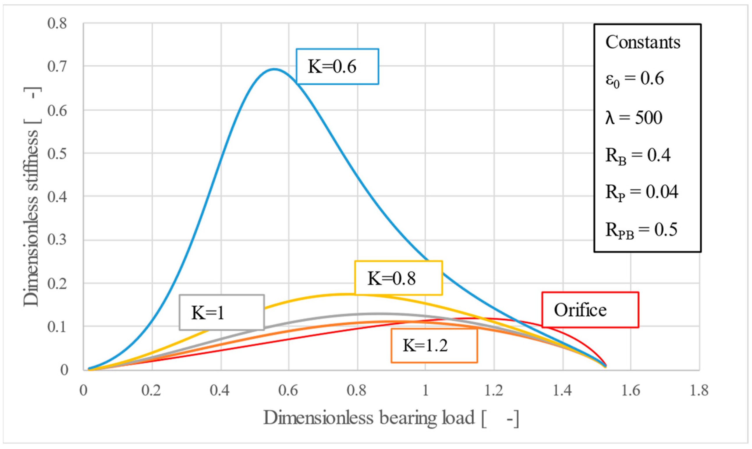
In
Figure 4, the variation of stiffness with respect to parameter
K is highlighted. By choosing different values of
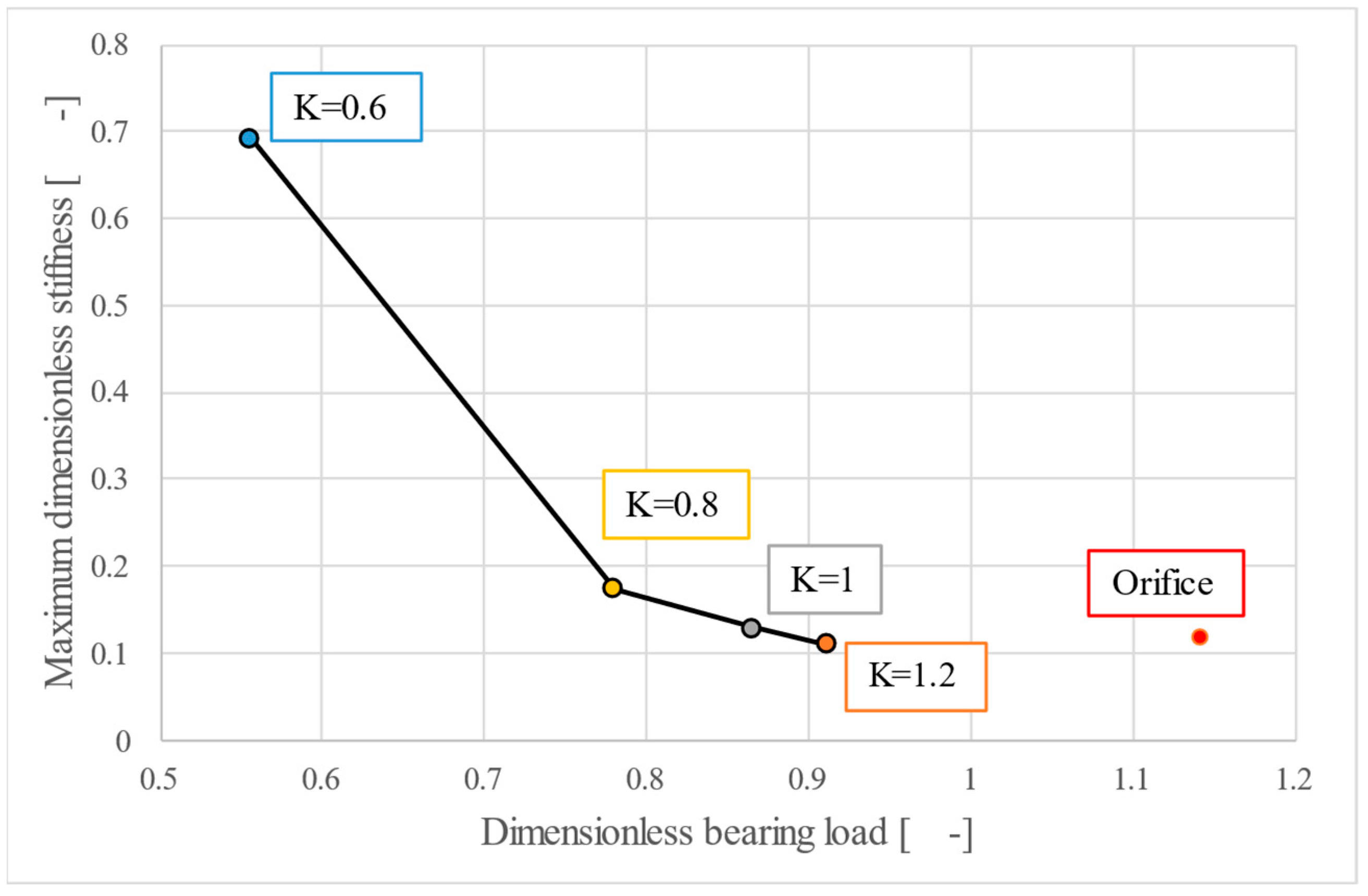
K, it is even possible to identify one that would determine a stiffness similar to that of the orifice. For a given bearing and porous material, the graph in
Figure 4 allows the engineer to choose the size of the spring.
Also, it can be observed that for smaller values of K, when the bearing load-film thickness characteristic slowly approaches the imaginary vertical, the increase in stiffness is exponential.
One key observation, highlighted in
Figure 5 is that the peak stiffness sits at different values of the bearing load. For instance, the orifice is better suited for high load applications while the porous restrictor is suitable for low to medium loads. It is worth noting that in practice thrust bearings are not subjected to forces equal to their maximum load capacity, so having high stiffness for low to medium values of the load is indeed beneficial.
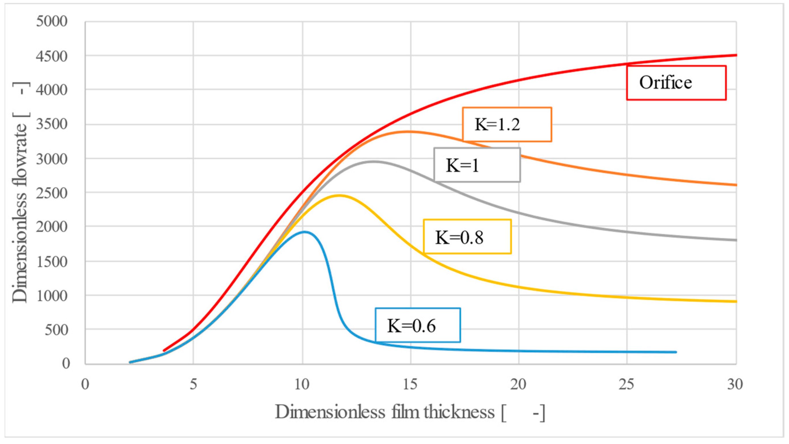
Figure 6 shows the dimensionless mass flowrate–film thickness characteristic, highlighting the efficiency of the new poro-elastic restrictor, which, for all values of
K, requires flowrates lower than that of the orifice.
As the load decreases, the pressure drop across the bearing falls off noticeably, more than the increase in film thickness, which explains the reduced flowrate at low loads. Meanwhile, the pressure drop inside the porous material rises, and the material itself becomes more compressed. Because the Kozeny-Carman permeability–porosity correlation was assumed, the flow through the porous medium declines sharply, which makes the system appear unstable at very small loads. If, instead, one used an experimentally determined permeability–porosity correlation different from Kozeny-Carman, the flow curve at low loads might look quite different.
Therefore, a double advantage can be identified, namely, that for lower values of K, for which the stiffness is high, there is also lower air consumption than the orifice.
Figure 7,
Figure 8 and
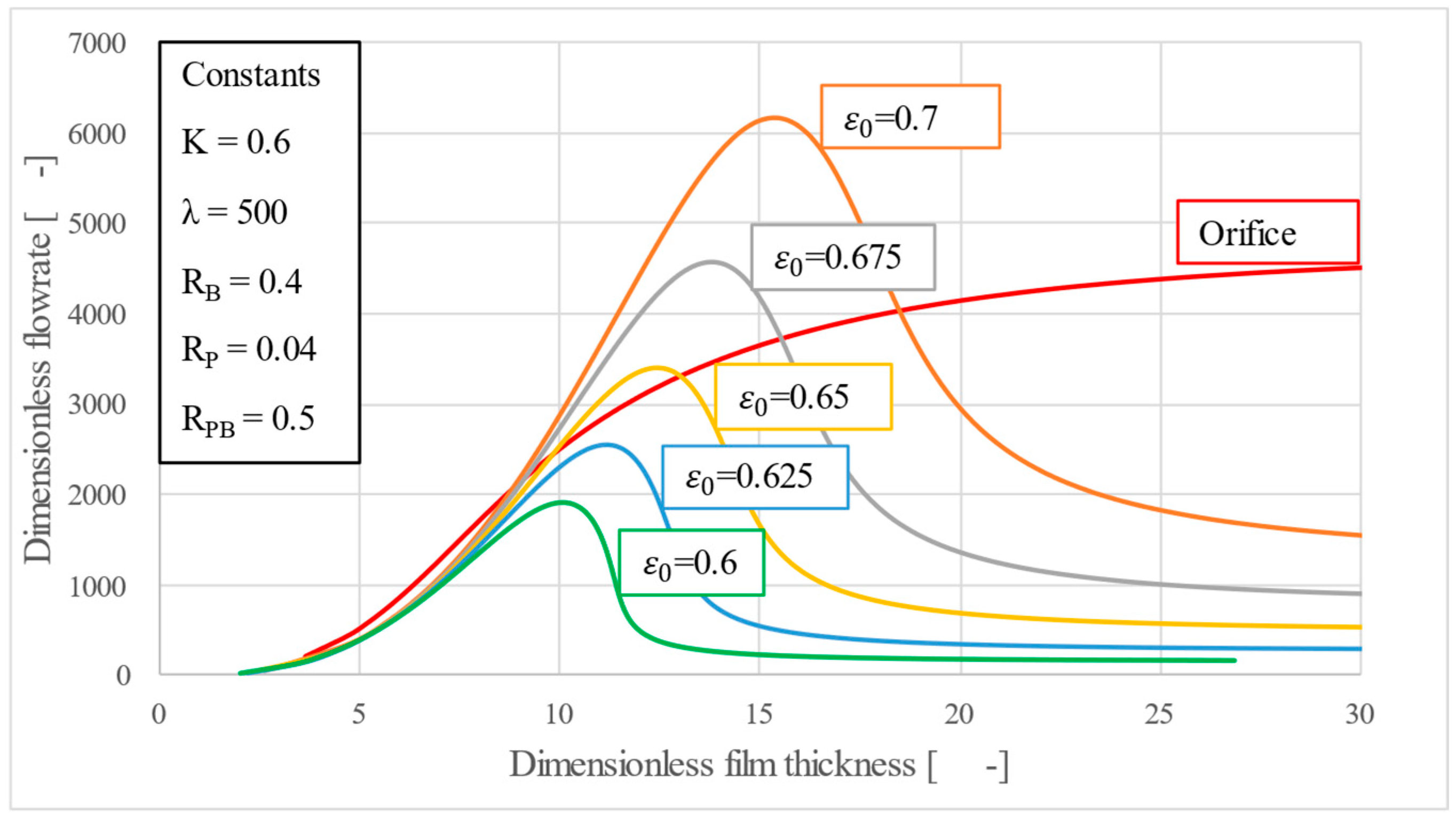
Figure 9 investigate the initial porosity parameter
ε0, whose permissible interval is narrow (±5%). Even this slight variation causes large deviations of the bearing load–film thickness slope. Furthermore, a single
ε0 that again renders the curve vertical—mirroring the behavior seen for
K—can be identified, but it would be difficult to obtain in practice.
Because ε0 cannot be tuned mechanically after fabrication, it must be held within tight material tolerances if we wish to hover near the quasi-infinite stiffness point without crossing into the unstable region. This underlines the need for accurate porosity measurement and quality assurance during production.
Unlike the spring stiffness parameter,
Figure 9 shows that the mass flowrate is much more sensitive to variations in porosity. A higher porosity opens the matrix and multiplies the air consumption. Thus, where air economy is paramount, specifying the lowest porosity compatible with stiffness targets is advisable, highlighting the importance of carefully selecting design parameters.
Figure 10 turn to the permeability parameter
λ, governed here by a Kozeny–Carman factor
. For example,
λ = 500 corelates to
for
, which corresponds to a permeability of 10
−13…10
−15 m
2, which is known to be the optimal range for gas lubrication (Constantinescu [
13]; Al-Bender [
30]). As shown in
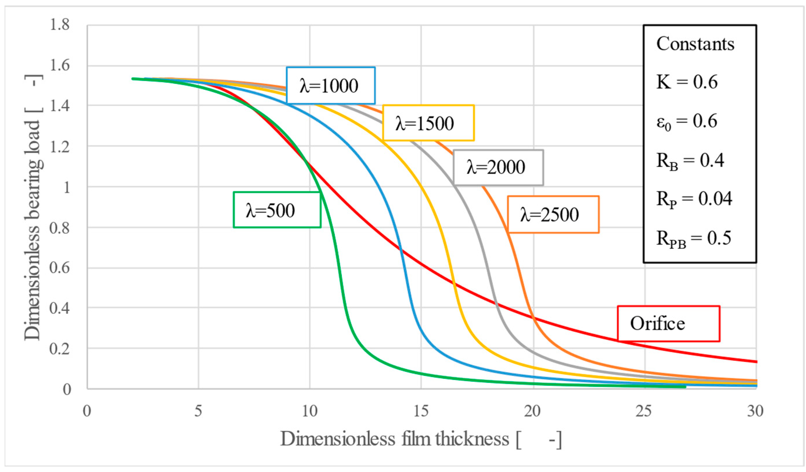
Figure 10, changing
λ translates the entire characteristic horizontally, effectively redefining the minimum and maximum film thickness, without affecting the stiffness. Their near-vertical appearance strengthens this fact.
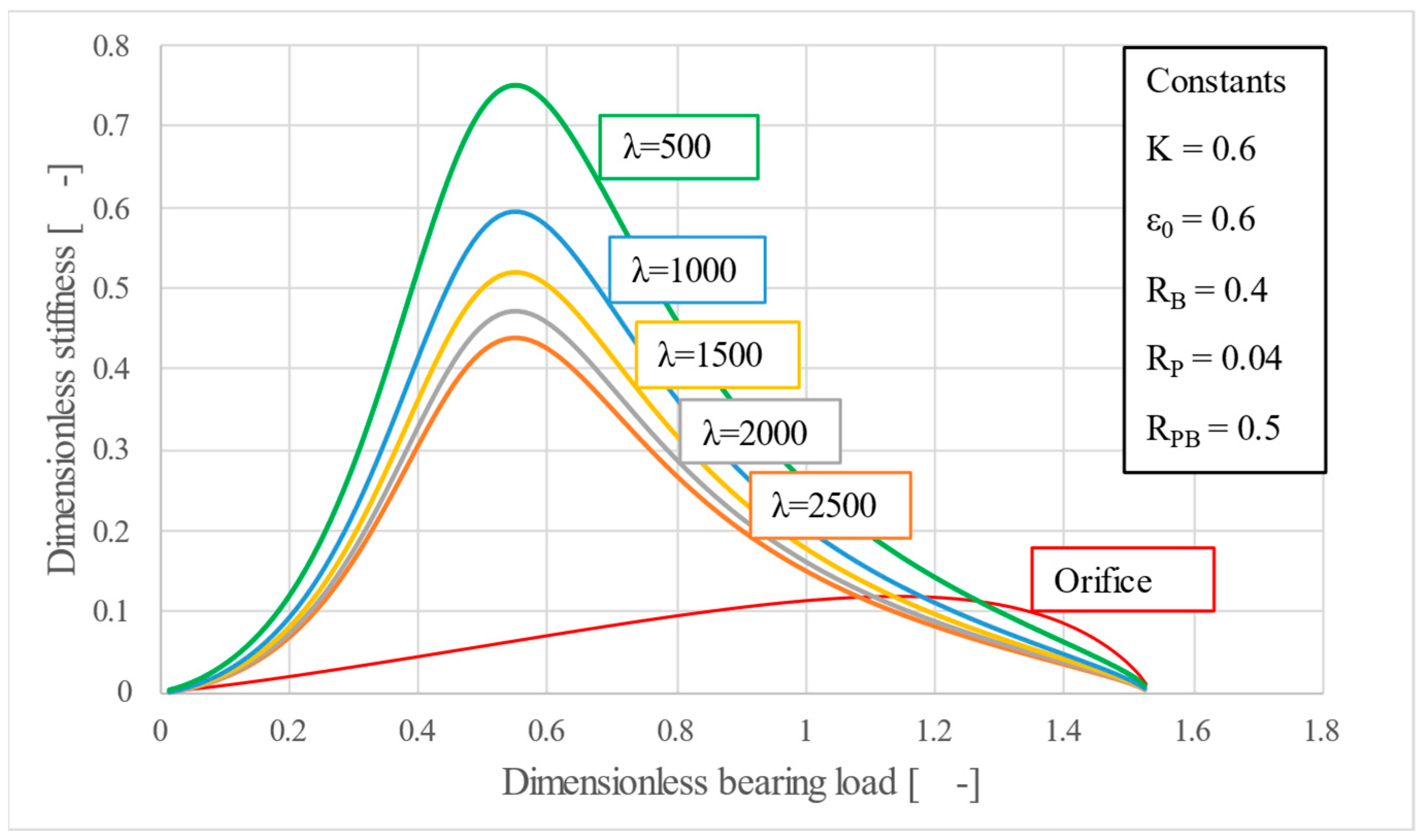
By observing
Figure 11, one can conclude, provided
K and
ε0 sit at convenient values,, that all curves in this case produced higher stiffness than the orifice, emphasizing that
λ is primarily a gap-placement parameter. It allows the designer to position the desired operating aerostatic clearance within practical bounds (typically 5…30 µm), without sacrificing the stiffness.
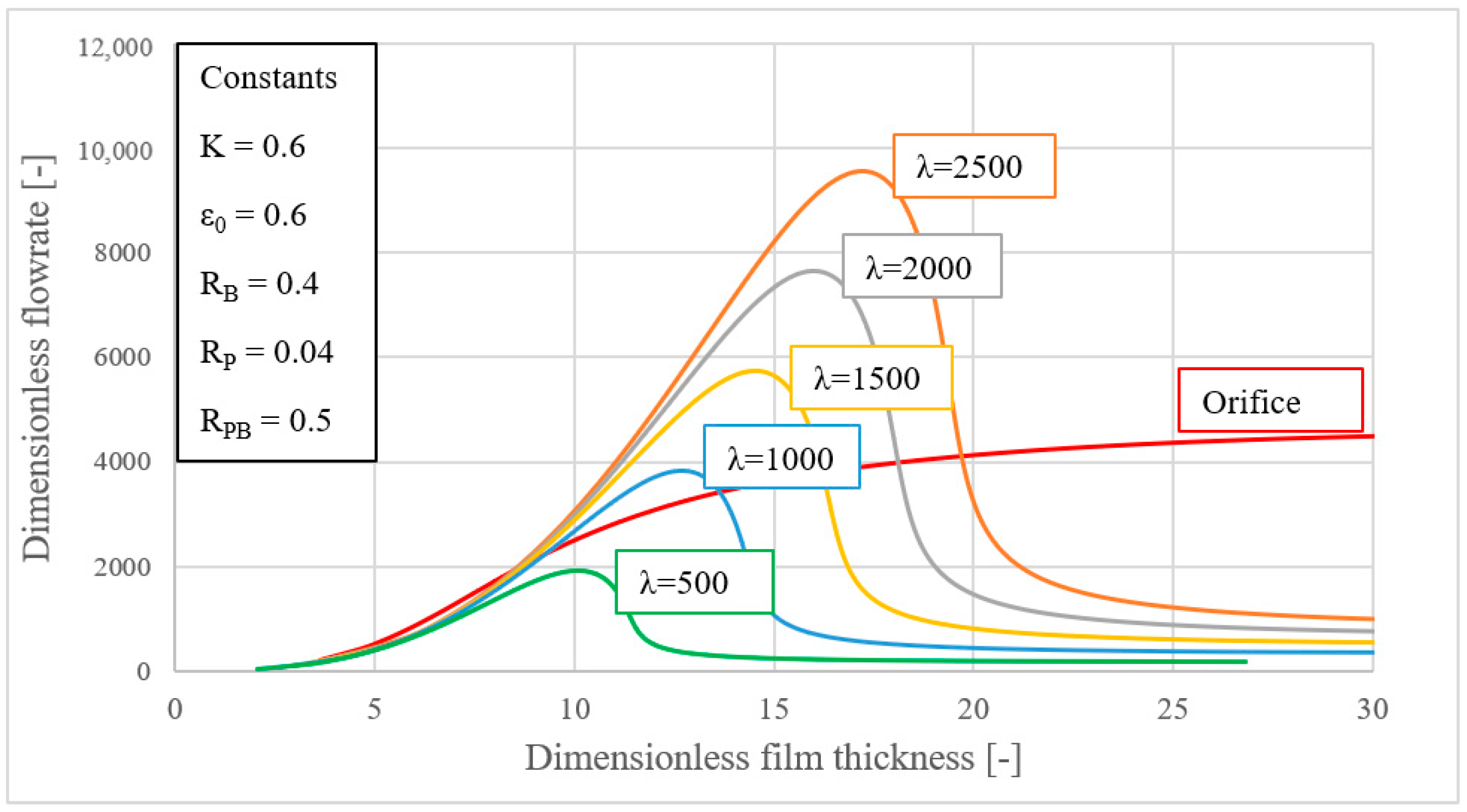
Figure 12, however, highlights a drawback, which is the much higher air consumption in comparison to the orifice, for almost all values of
λ, when
h = 10…20 µm, which corresponds to a large interval of bearing loads, since a higher permeability inevitably demands more air. Thus, it is once again brought into the spotlight the importance of choosing the optimum combination of parameters to satisfy all design requirements, while maintaining a manufacturable range of values.
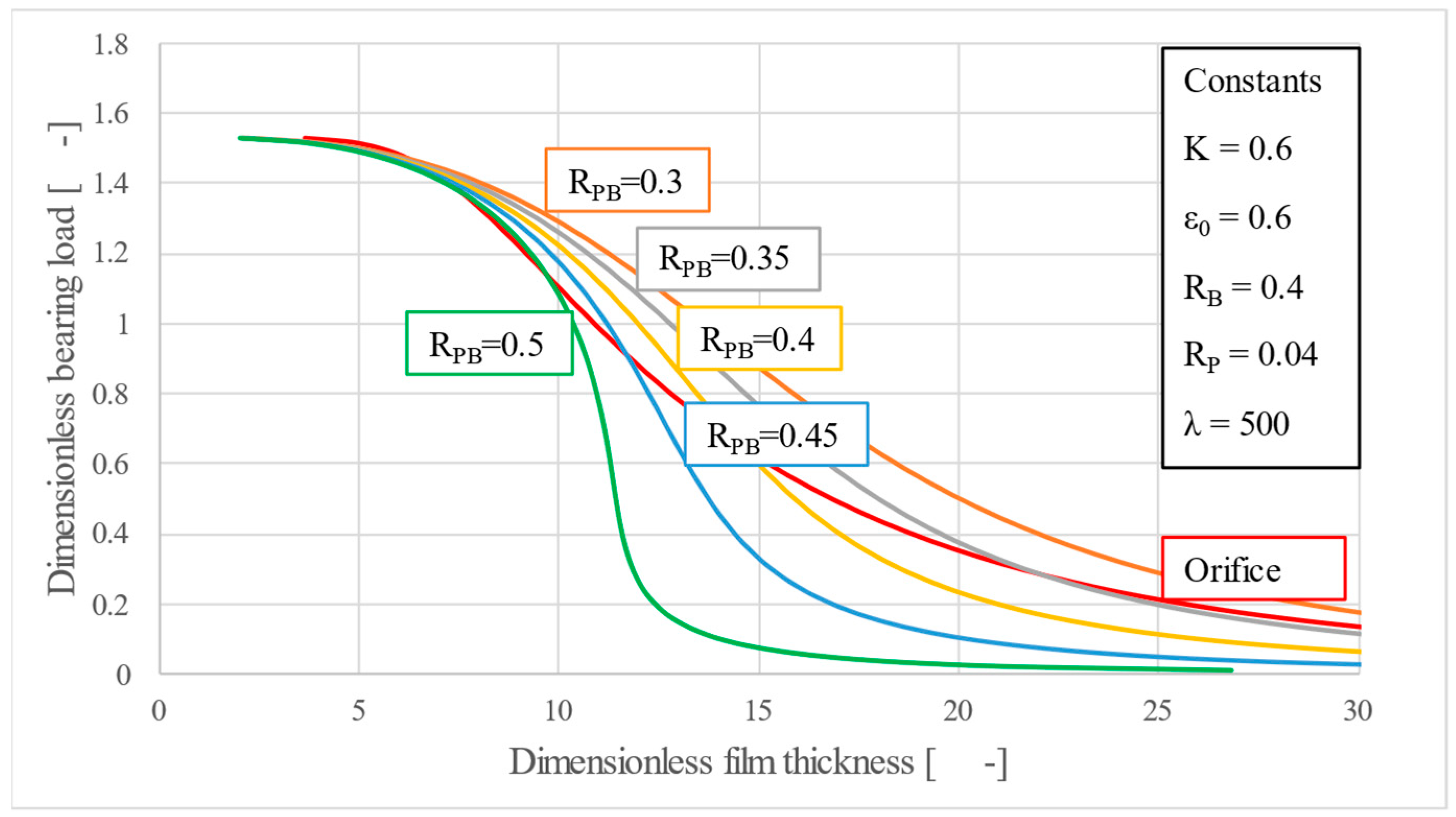
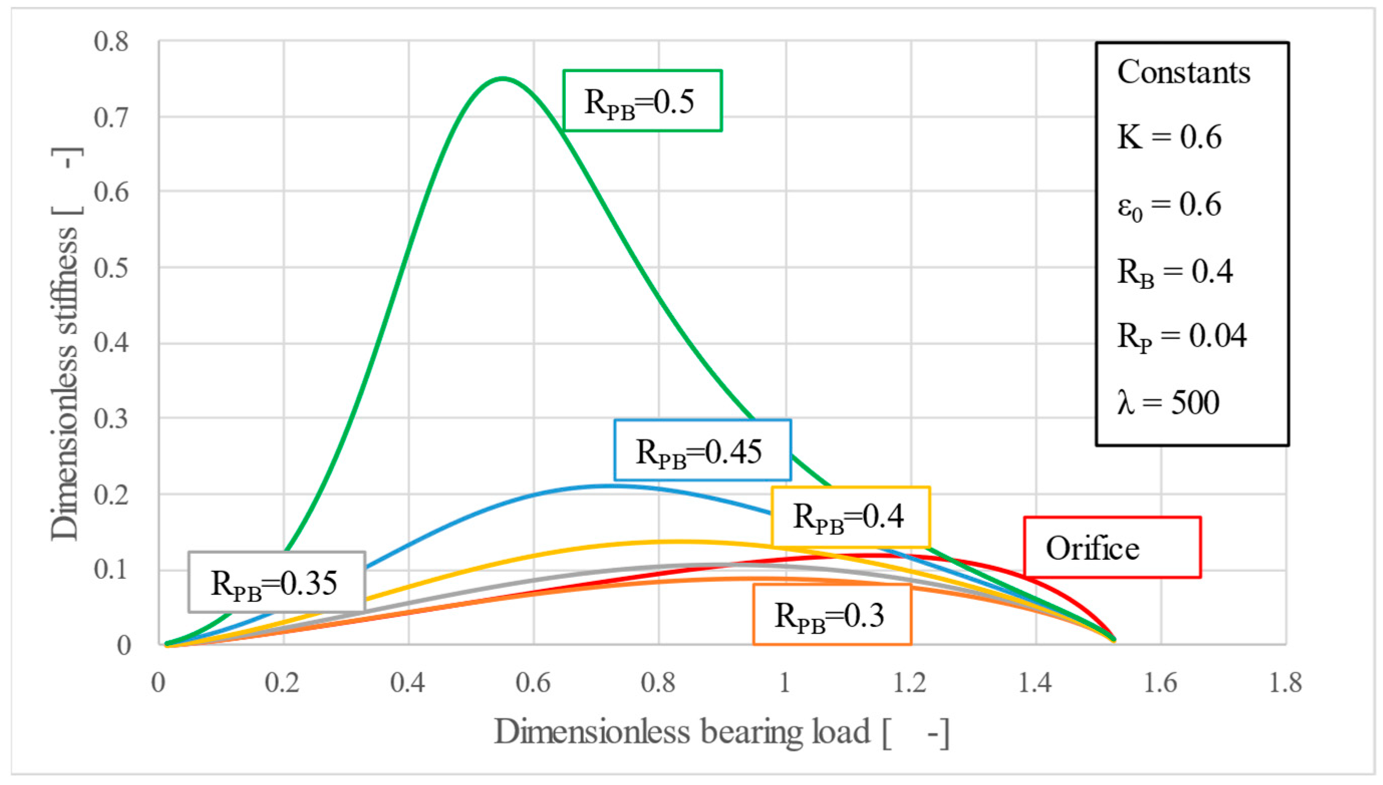
Unlike the previous three parameters, the porous disc relative radius
RPB is a size parameter, used for describing the relation between the porous disc and the bearing. Observing
Figure 13 and
Figure 14, one can notice a behavior of the bearing load-film thickness and stiffness-bearing load characteristic, very similar to the one obtained through the variation of parameter
K. Similarly,
RPB mainly influences the slope of the characteristic curves, making it possible to find a solution that would result in a very high static stiffness, bending the lower half of the curve to an almost vertical position. This proves that geometric scaling, through the variation of the porous disc’s outer radius, can be exploited to fine-tune performance when spring optimization alone is insufficient.
For all evaluated size ratios, the poro-elastic restrictor still outperforms the orifice in air economy (
Figure 15). Because flow falls as
RPB shrinks, choosing the smallest disc compatible with assembly space gives additional consumption savings. Again, this behavior is similar to the characteristics of parameter
K, highlighting both of them as key tuning parameters.
4. Conclusions
This study introduced a novel poro-elastic restrictor model for aerostatic bearings, which has the ability to self-adjust with respect to the bearing load. Under increasing load the porous core compacts, the mass flowrate adjusts, and the gas film stays almost constant. Through a parametric analysis, it was shown that its behavior is governed mainly by four dimensionless parameters: the spring stiffness parameter K, the initial porosity ε0, the permeability parameter λ, and the porous disc relative radius RPB.
Among these, the spring stiffness parameter K is the easiest to modify late in the build. A stiffer spring shifts the bearing load-film thickness curve towards larger gaps and makes it steeper, delivering very high stiffness without a surge in air consumption. Pushing K too far towards low values, however, and the curve folds back, creating a pocket of negative stiffness and potential instability—so the sweet spot lies just to the right of that imaginary turning point. Because springs can be swapped or pre-loaded on the bench, K offers a practical route for last-minute tuning.
The initial porosity ε0 plays a similar, but less forgiving, role. Variations of only a few percent can move the bearing load-film thickness curve from the desirable characteristic. Unlike K, ε0 is frozen once the disc is fabricated, so tight material control and reliable porosity metrology are indispensable if the design is to hover safely near the preferred region, without losing too much stiffness or stability.
Permeability parameter λ behaves like a horizontal translation parameter rather than having an effect on stiffness: changing it slides the whole bearing load–film thickness characteristic sideways, while leaving the slope almost untouched, letting the engineer choose the working gap inside the usual aerostatic range (5…30 µm) without sacrificing stiffness. The model points to low permeabilities—10−13 to 10−15 m2—yet those figures are now within reach thanks to additive or hybrid routes. If experimental data favor a different porosity–permeability law, the Kozeny–Carman equation used here can simply be swapped for any correlation that fits better, giving designers extra freedom without rewiring the theory.
Geometric tuning through the porous disc relative radius RPB resembles the behavior of the spring stiffness parameter K, making it a good tuning alternative when changing the spring stiffness is not enough.
In direct comparison with an orifice sized for equal load capacity, the optimized poro-elastic pad delivers markedly higher stiffness in the low-to-medium load band while drawing less air except at the thinnest clearances.
Future work should measure the real permeability-compression behaviour of candidate materials, determine both static and dynamic stiffness around the turning point, and carry out high-fidelity CFD simulations of the coupled porous matrix and gas film to test the model’s assumptions and guide further design refinements before hardware is built.
