2.2. Mathematical Model
To facilitate the research, the following basic assumptions are made for the computational model:
(1) Since the body forces and inertial forces are relatively small compared to the viscous forces, the volume forces and inertial forces of the lubricating gas are ignored.
(2) The lubricating medium is hydrogen gas, and given the relatively low rotational speed, it is assumed that the sealing gas behaves as a Newtonian fluid, with laminar flow and no turbulence.
(3) The lubricating gas is assumed to be in a state of isothermal continuous flow.
(4) The lubricating gas is a viscous fluid, so it is assumed that there is no slip during rotation.
(5) Given that the research is conducted at relatively low temperatures and pressures, it is assumed that the sealing rings are rigid and do not deform.
(6) The lubricating film is a micron-thick layer; compared to axial and circumferential pressures, the pressure variation in the radial thickness direction can be neglected.
For cylindrical seals, Brunetiere et al. summarized prior experimental studies on the lower critical Reynolds number and the upper critical Reynolds number. This implies:
Rec < 900, the flow is laminar;
900 < Rec < 1360, the flow is in a transitional regime;
Rec > 1360, the flow becomes turbulent.
The classical Reynolds equation can be applied directly for laminar flow, whereas transitional and turbulent flows require coefficient corrections to the classical Reynolds equation. Therefore, the Reynolds number is essential prior to further analysis. In this study, the minimum film thickness
h is 7 μm, the maximum is 36 μm, and the shaft radius
r is 25 mm. The resulting
h/
r ratio ranges from [2.8 × 10
−4, 1.44 × 10
−3], which satisfies the interval [10
−3, 10
−4]. The Reynolds number for cylindrical gas film seals is calculated as:
where
is fluid density (kg/m
3),
is rotational speed (rad/s),
r is shaft radius (m),
h is film thickness (m), and
is dynamic viscosity (Pa·s).
The operational temperature range is [300 K, 700 K], and the inlet pressure range is [1 MPa, 2 MPa]. Using the REFPROP property database, the calculated property ranges are as follows:
Viscosity ranges from [8.94 × 10⁻⁶, 1.611 × 10⁻⁵] Pa·s; density ranges from [0.34, 1.59] kg/m3; and film thickness is between [12 × 10−6, 3.6 × 10⁻⁵] m. Rotational speed varies from [10,000 × 2π/60, 40,000 × 2π/60] rad/s. Therefore, the calculated Reynolds number is approximately 400.
The Knudsen number,
Kn, determines the applicability of continuum flow assumptions:
Kn < 0.01: Continuum regime; 0.01 <
Kn < 0.1: Slip flow regime;
Kn > 0.1: Non-continuum regime. The Knudsen number is defined as:
where
is the mean free path of gas molecules (μm), and
h is the characteristic flow dimension (μm), which is equivalent to film thickness. For hydrogen gas under standard conditions, the minimum film thickness h is 1.2 × 10
−5, yielding
Kn < 0.01. This confirms the flow operates in the continuum regime, validating the use of the classical Reynolds equation.
2.3. Steady State Reynolds Equation
The Reynolds equation describes the distribution of pressure in the gas film during the lubrication process. Based on the assumptions mentioned above, the steady-state Reynolds equation in cylindrical coordinates is introduced.
where
p is the pressure of the sealing gas;
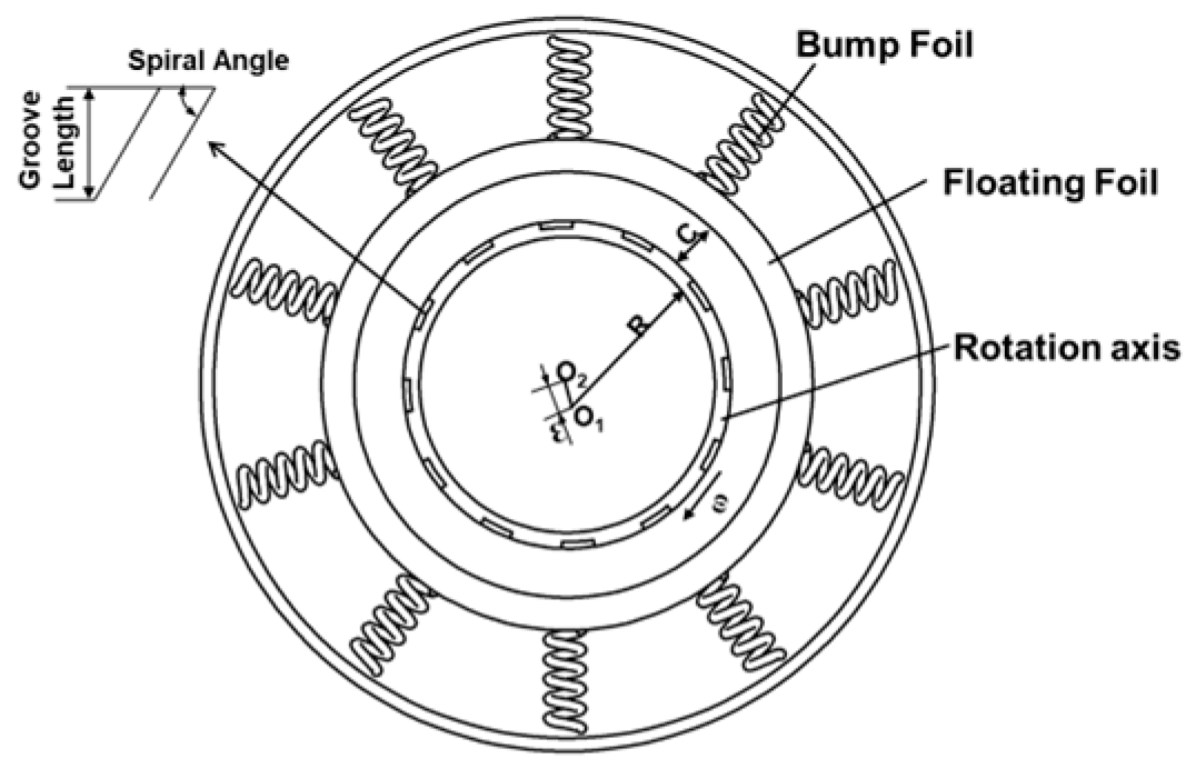
R is the sealing radius;
ρ is the density of the sealing gas; h is the film thickness;
η is the viscosity of the sealing gas;
ω is the angular velocity;
θ is the circumferential direction; and
z is the axial direction. The Reynolds equation is discretized using a five-point finite difference method, with initial conditions set and an iteration precision of 10
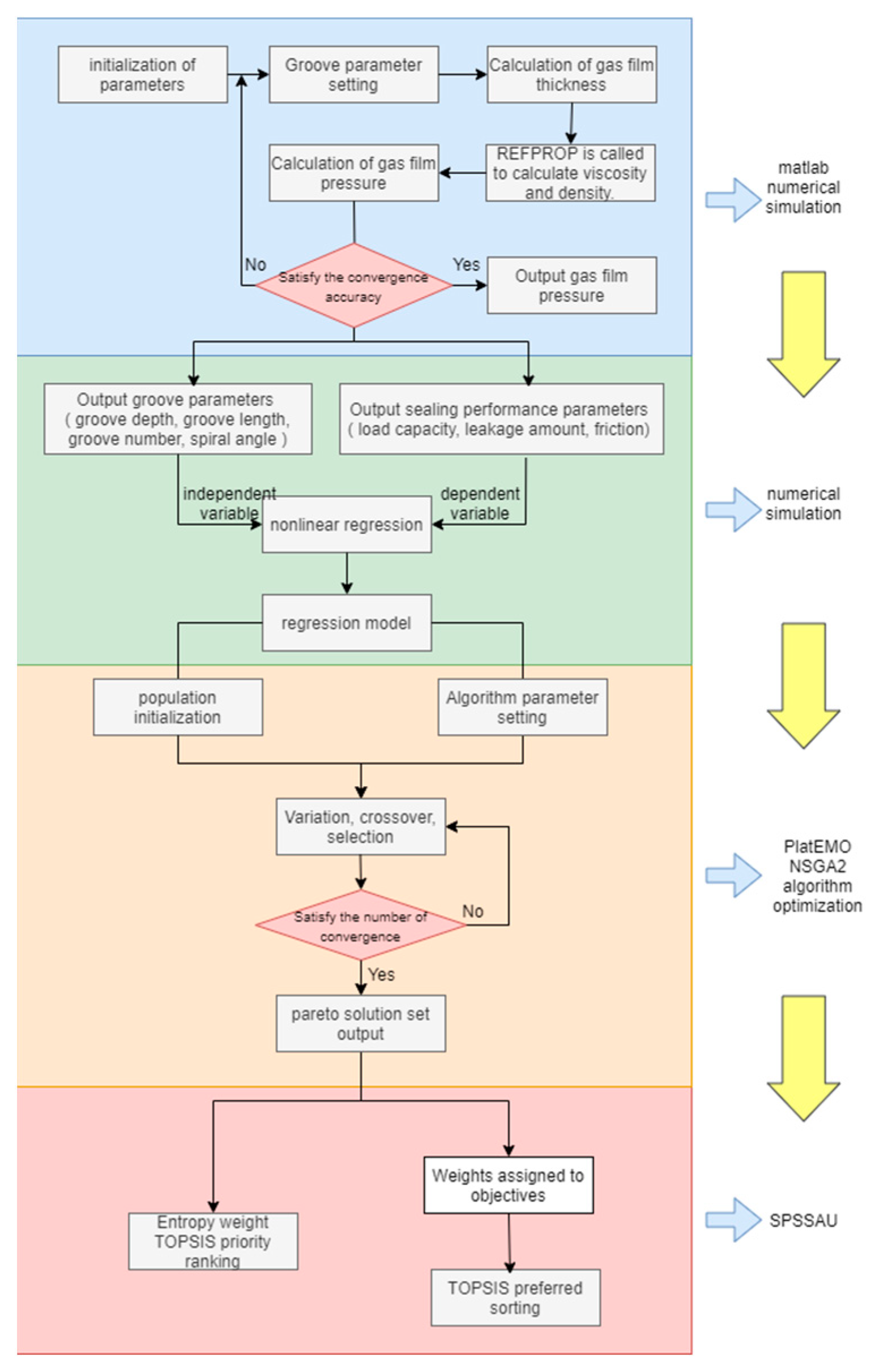
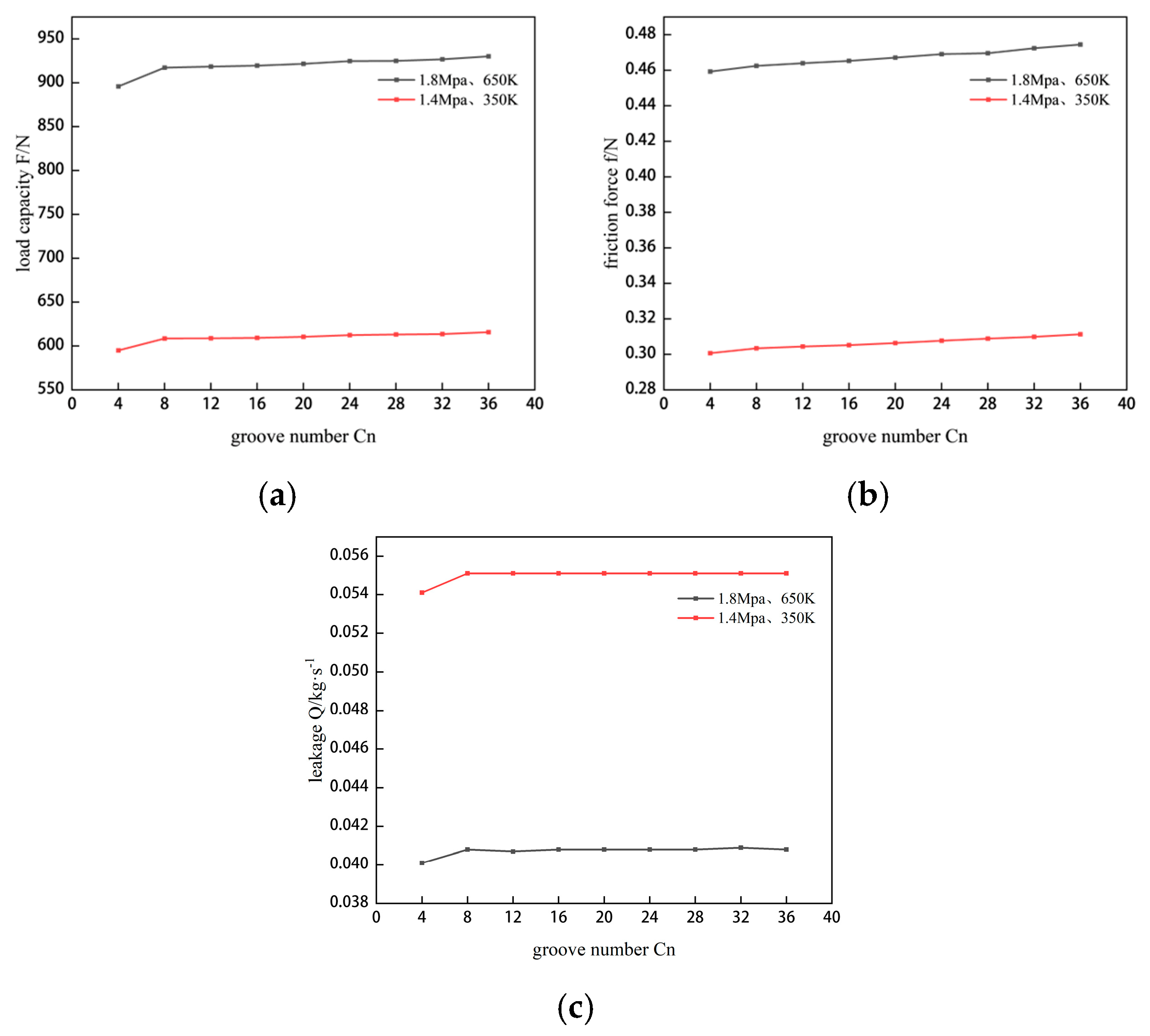
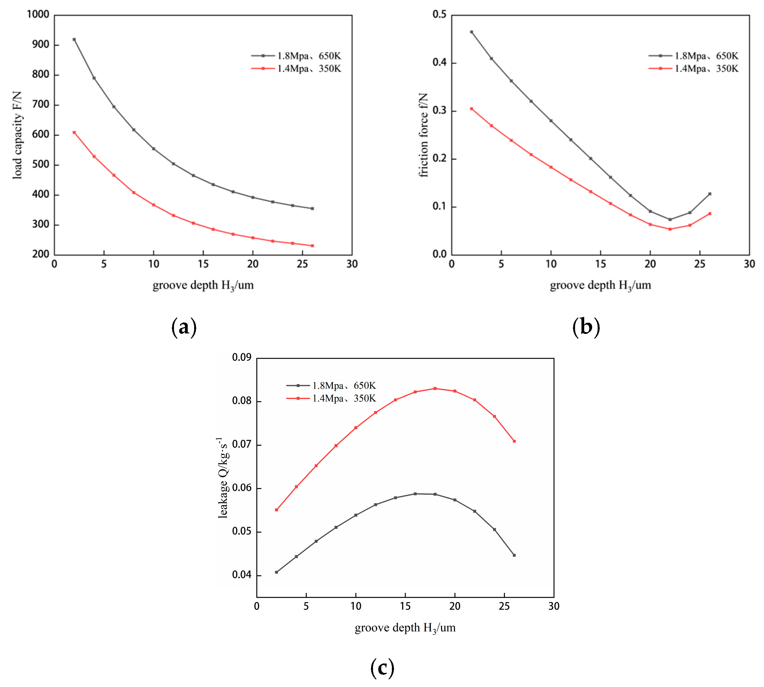
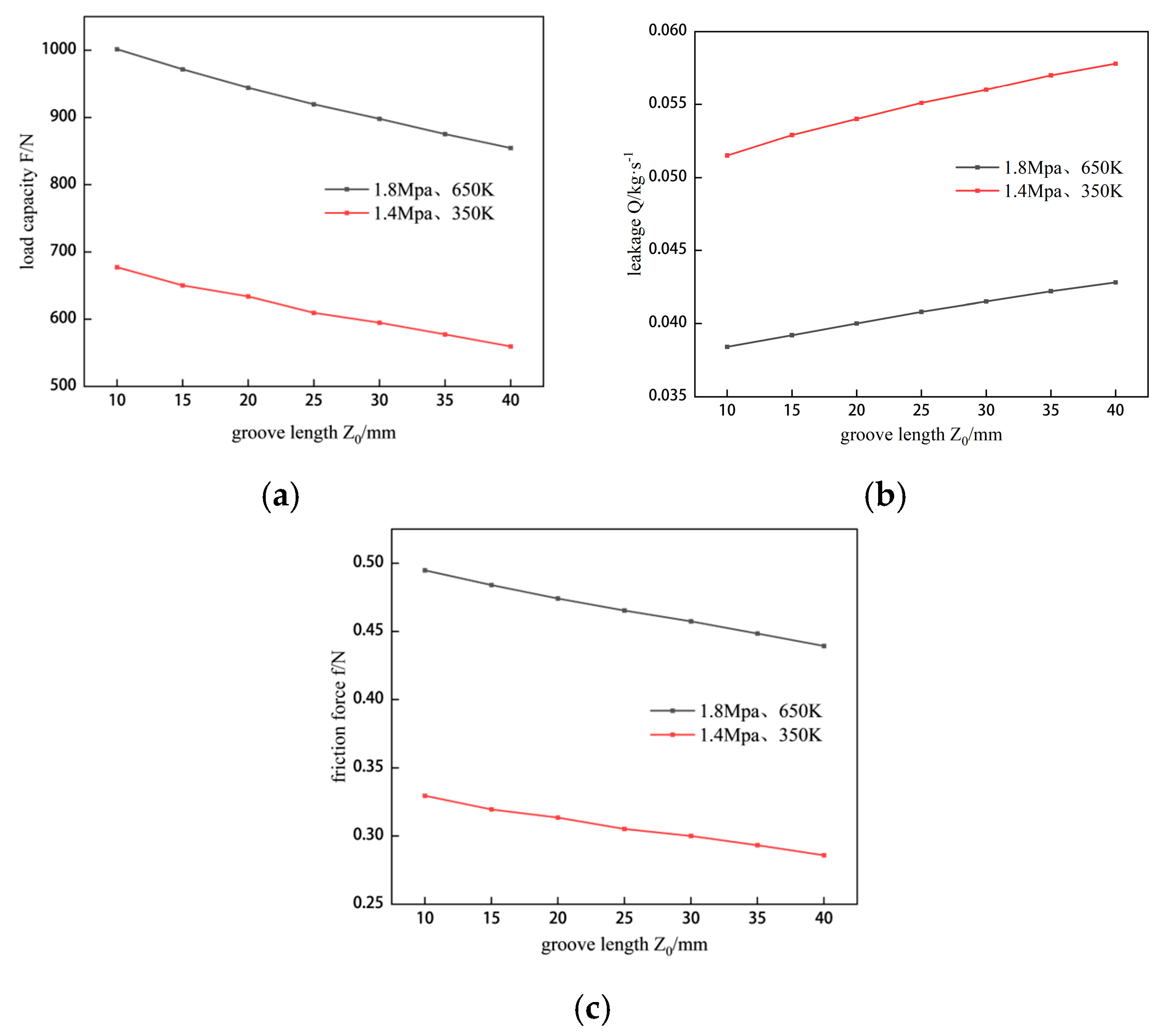
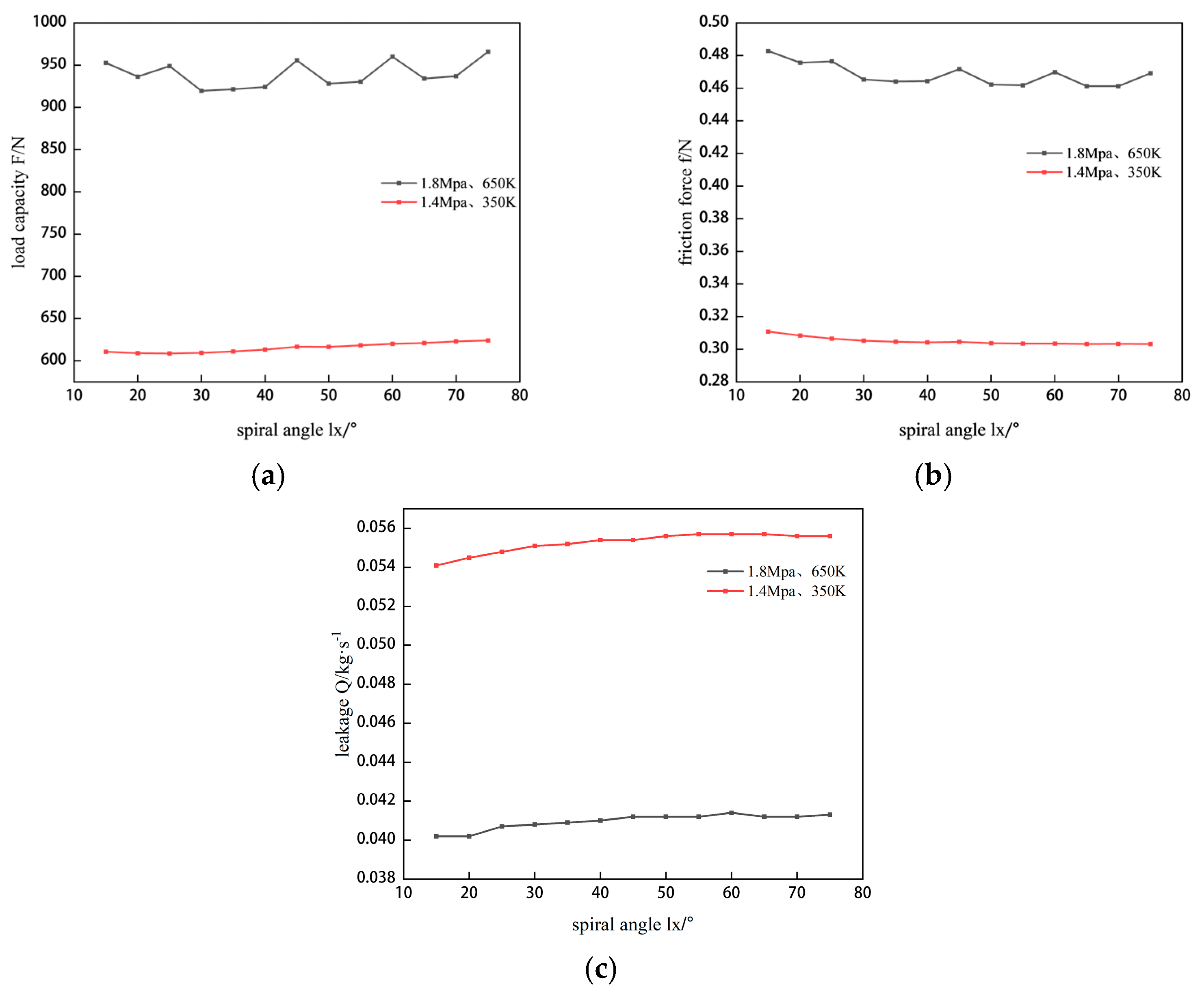
−6. The final results include load capacity, friction force, and leakage amount. By adjusting the number of spiral grooves, groove width, groove depth, and spiral angle, corresponding values of sealing performance are obtained, and the reasons for these changes are explained and analyzed. Next, nonlinear fitting analysis is conducted, with spiral groove parameters as independent variables and sealing performance as the dependent variable. Subsequently, NSGAII is used for optimization design, with a population size set to 100 and 200 iterations to obtain the Pareto solution set. Finally, the best solution is selected using both subjective TOPSIS and objective entropy weight TOPSIS methods. Details are provided in
Figure 2.
The leakage amount
Q, gas film lift force
F, and friction force f of the cylindrical seal are key parameters for evaluating sealing characteristics, with their respective calculation formulas as follows: Gas film load capacity:
where
Fh is the dimensionless vertical component of the load capacity;
Fv is the dimensionless horizontal component of the load capacity; and
is the dimensioned load capacity. Leakage amount:
where
is the dimensionless leakage rate, and
Q is the leakage rate. Viscous friction force:
where
fh is the dimensionless vertical component of the viscous friction force;
fv is the dimensionless horizontal component of the viscous friction force;
is the dimensioned viscous friction force where
is the dimensionless pressure;
is the dimensionless thickness;
is the dimensionless viscosity;
is the dimensionless density;
C is the average gas film thickness;
L is the sealing width;
is the viscosity of the ambient gas;
is the density of the ambient gas; and
is the dimensionless axial coordinate.
To investigate the mechanisms by which structural and operational parameters affect the steady-state sealing performance of hydrogen in a supercritical state, the sealing structure from the literature is adopted, and the parameters listed in
Table 1 and
Table 2 are utilized for the research.

 ,
, 

