Abstract
This study fabricated a C/C-CuNi composite using the hydrothermal co-deposition method and investigated its friction and wear behavior as well as the underlying mechanisms after being subjected to arc discharge ablation. The results indicate that the graphitization degree of the material matrix was significantly enhanced after arc discharge ablation, accompanied by a transformation in the carbon microstructure. Carbon nanotubes and graphene structures were generated in the arc ablation zone. Under low arc discharge density, limited pits and open pores are formed on the material surface, with the generated graphene structures effectively reducing friction. Specifically, CN-5 exhibited a stable friction coefficient, a wear rate of 5.2 mg/km, and partial self-repair capability. In contrast, CN-10, under high arc discharge density, suffered from structural collapse, matrix-fiber debonding, and extensive open pores, leading to increased surface roughness. The combined effects of frictional heat and Joule heating elevated the wear surface temperature, triggering matrix oxidation and a sharp rise in wear rate to 14.7 mg/km. The wear mechanisms of C/C-CuNi composites under continuous arc conditions involve arc erosion wear, oxidative wear, abrasive wear, and adhesive wear.
1. Introduction
Pantograph slide plates are critical components on electric trains, collecting power through friction with overhead wires to drive motors. However, at speeds exceeding 350 km/h, severe arc erosion caused by high-speed friction significantly damages these plates, compounding their existing challenges of mechanical wear and environmental corrosion [1,2]. Improper contact from vibration or icing can generate electric arcs, causing surface softening, erosion pits, and adhesive wear on the contact wire. This electrical wear is 3 to 14 times more severe than mechanical wear, drastically shortens the pantograph slide plate’s lifespan, and accelerates its failure [3,4,5].
Current pure carbon slide plates rely on abrasive powder from high-speed sliding to form a protective carbon film on contact wires, reducing friction [6]. However, their carbon composition results in low mechanical strength, making them prone to fracture under impact and posing safety risks. Pure carbon skateboards exhibit higher resistance and lower current-carrying capacity, causing excessive thermal oxidation, crater formation, and accelerated wire wear under high temperatures [7,8,9]. In contrast, metal-impregnated carbon skateboards fill carbon matrix pores with metal, creating a dense structure that combines carbon and metal advantages while enhancing mechanical strength beyond pure carbon designs [10]. However, metal-impregnated carbon skateboards suffer from low-impact toughness, fracture-prone structures, debris shedding, and even pantograph breakdowns, often failing prematurely before reaching wear limits due to high maintenance costs [11,12]. This necessitates a material system redesign to improve operational lifespan in complex environments and meet future application requirements.
C/C-Cu composites, a novel metal matrix composite with dual structural and functional properties, combine high strength, fracture toughness, thermal shock resistance, and low thermal expansion [13,14]. Their adaptability to harsh environments makes them promising for high-performance conductive/wear-resistant applications such as pantograph slides and brushes [15,16,17]. Yin et al. [18] prepared a copper mesh-modified carbon/carbon (C/C-Cu) composite by chemical vapor impregnation (CVI) and impregnation-carbonization (I/C) using carbon fiber needle-punched fabrics with copper mesh and graphite powder as prefabricated parts. The Cu mesh is uniformly dispersed in the C/C-Cu composites, and the pyrolyzed carbon shows a rough laminar structure. Both C/C and C/C-Cu composites showed good wear resistance. The results show that C/C-Cu composites have the best current-carrying capacity and wear properties under 80 N applied load. Deng et al. [7] proposed a novel Cf/Cu/C composite material consisting of a two-dimensional reticulated copper network and a three-dimensional reticulated carbon fiber matrix. The effect of current magnitude on the friction and wear properties of Cf/Cu/C composites is investigated.
Despite mature applications in pantograph slides, C/Cu composites face challenges, including poor C/Cu wettability (hindering densification), density mismatch-induced non-uniform distribution, and non-reactive interfaces [19,20]. These result in weak interfacial bonding, porosity, and defects that accelerate wear and destabilize friction coefficients [21]. For this reason, some researchers have found that Ni and Cu can show infinite mutual solubility, and the introduction of Ni can significantly improve the wettability of the C/Cu composite interface, enhance the interfacial strength of the composite material, and improve its friction and wear performance [22,23,24,25]. The friction and wear properties of C/C-CuNi composites under a humidity environment were investigated by wang et al. [26]. It was shown that the addition of Ni can significantly improve the interfacial wetting between C/Cu and make the interfacial bonding between the two closers, and the addition of Ni reduces the pores and defects between C/Cu and significantly improves the friction and wear performance of the material.
At present, C/C-Cu composites are mainly prepared by immersion infiltration, chemical vapor deposition, hot press sintering, and metal fusion infiltration [27,28,29]. Yuan et al. [30] prepared carbon fiber and copper powder-modified resin composites by mechanical blending, hot press polymerization, and impregnation treatment. These composites have higher electrical conductivity and bending strength than pure carbon ribbons but insufficient wear resistance. Cui et al. [31] prepared a novel carbon fiber 2.5D woven prefabricated reinforced C/C-Cu composite using a pressureless infiltration technique, which solved the problem of poor wettability of metallic copper to carbon materials. However, the commercial application of C/C composites prepared by chemical vapor phase infiltration is costly; materials prepared by impregnation are not suitable for engineering applications due to poor electrical conductivity and wear resistance.
Compared to the above methods, the hydrothermal-co-deposition method significantly improves the synthesis efficiency due to the simple equipment required and mild reaction conditions. At the same time, this method enables the CuNi particles to be uniformly deposited in the substrate material, effectively avoiding elemental segregation and significantly enhancing interfacial bonding [32].
This work proposes a novel copper-infiltration-free method—hydrothermal co-deposition and carbothermal reduction—to prepare C/C-CuNi composites. To further enhance electrical conductivity, Ni element is introduced during the co-deposition process: Ni catalyzes the graphitization of amorphous carbon to improve conductivity, while the infinite mutual solubility of Ni-Cu optimizes C/Cu interfacial wettability and bonding strength. The effects of different discharge densities on the microstructure and friction and wear properties of C/C-CuNi composites are discussed. The friction and wear mechanism of C/C-CuNi composites after arc discharge is revealed, which provides another feasible idea for the research and development and improvement of the material system of pantograph sliding plate under extreme arc discharge environment.
2. Materials and Methods
2.1. Materials
Carbon mats were supplied by Jiangsu Tianbird Co., Ltd., Yixing, China, with an initial density of 0.3–0.4 g/cm3. Copper nitrate pentahydrate, glucose, urea, and anhydrous ethanol were supplied by Sinopharm Chemical Reagent Co., Ltd., Shanghai, China, with all of the analytical purity (AR grade). Nickel nitrate hexahydrate was supplied by Shanghai Aladdin Biochemical Technology Co., Shanghai, China.
2.2. Preparation of C/C-CuNi Composite
A mixed aqueous solution containing glucose, urea, nickel nitrate hexahydrate (Ni (NO3)2·6H2O), and copper sulfate pentahydrate (CuSO4·5H2O) was prepared as the precursor solution, with a controlled C:Cu:Ni molar ratio of 5:0.5:0.3. The glucose concentration was fixed at 1.5 mol/L while urea (0.25 mol/L) served as the alkaline source. After vacuum impregnation treatment (<0.1 MPa, 1 h) of C/C preforms in the precursor solution, the samples were subjected to hydrothermal co-deposition in a sealed reactor at 200 °C for 5 h. In the hydrothermal co-deposition process, urea acts as a precipitant and reacts with Cu2+ and Ni2+ in a precipitation reaction to generate Cu(OH)2 and Ni(OH)2, which are filled in the C/C precast body. At elevated temperatures, Cu(OH)2 and Ni(OH)2 decompose thermally into CuO and NiO. During subsequent heat treatment, these oxides undergo carbothermal reduction with hydrothermal carbon deposited in the C/C preform. The resulting elemental Cu and Ni infinitely interdiffuse to form a CuNi alloy. The resulting C/C-CuO-NiO composites were obtained through subsequent drying and polishing procedures. Finally, carbothermal reduction was performed at 1200 °C for 2 h under an inert atmosphere to transform the metal oxides into metallic phases, yielding the C/C-CuNi composite material. Figure 1 shows the preparation process of C/C-CuNi composites (heating rate: 0–1000 °C, 10 °C/min; 1000–1200 °C, 5 °C/min).
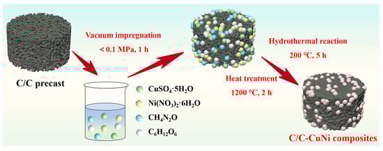
Figure 1.
Preparation process flow chart of C/C-CuNi composite.
2.3. Characterization
The microscopic morphology of the C/C-CuNi composites, as well as the morphological changes of the wear marks and abrasive chips after the friction experiments, are investigated by scanning electron microscopy (HITACHI, Tokyo, Japan) and transmission electron microscopy (FEI, Hillsboro, OR, USA). The graphitization of C/C-CuNi composites is analyzed using a Renishawinvia Raman instrument manufactured by Renishaw, London, UK. Where the excitation wavelength is 532 nm, and the working range is 100~3200 cm−1. The phase composition of C/C-CuNi composites is analyzed using an X-ray diffractometer (Nihon Rikaku Co., Tokyo, Japan) with a Cu target, working scanning range of 10°~80°, and a working scanning rate of 8 deg/min. The surface elemental and chemical compositions of the C/C-CuNi composites are analyzed using a Fourier infrared spectrometer (Thermo Fisher Scientific, Waltham, MA, USA) and an X-ray photoelectron spectrometer (Shimadzu, Kyoto, Japan).
2.4. Arc Discharge Test
We perform high-voltage arc discharge on the C/C-CuNi composites using a linear DC-regulated power supply (220 V, 0.1–10 A). The composite sample is clamped in an adjustable fixture connected to the power supply, while a conductive Cu-Zn alloy wire electrode contacts its surface to form a closed circuit, initiating arc discharge between the electrode and composite. The friction and wear properties of C/C-CuNi composites are investigated by adjusting the arc discharge density, and 3 sets of variables are designed for 0, 5, and 10 arc discharge points in an area of 1 cm2, respectively, and the experimental design is shown in Table 1.

Table 1.
Experimental design of arc discharge of C/C-CuNi composite.
The friction and wear performance of the samples is tested by a CFT-I comprehensive material surface performance tester. The test specimen was 20 mm × 20 mm × 5 mm. The contact surface of the copper-tin alloy slider is 12 mm × 5 mm, and the sliding speed is 200 km/h. The coefficient of friction and wear rate of the samples are given in Equations (1) and (2) as follows:
where μ represents the coefficient of friction of the material, f denotes the friction force, N denotes the load applied to the material, W denotes the wear rate, m0 is the pre-wear mass, m1 is the post-wear mass, L is the reciprocal length, and S represents the cross-sectional area of the wear marks measured by the super depth-of-field 3D microscope.
3. Results
3.1. Microscopic Morphology and Physical Phase of C/C- CuNi Composite
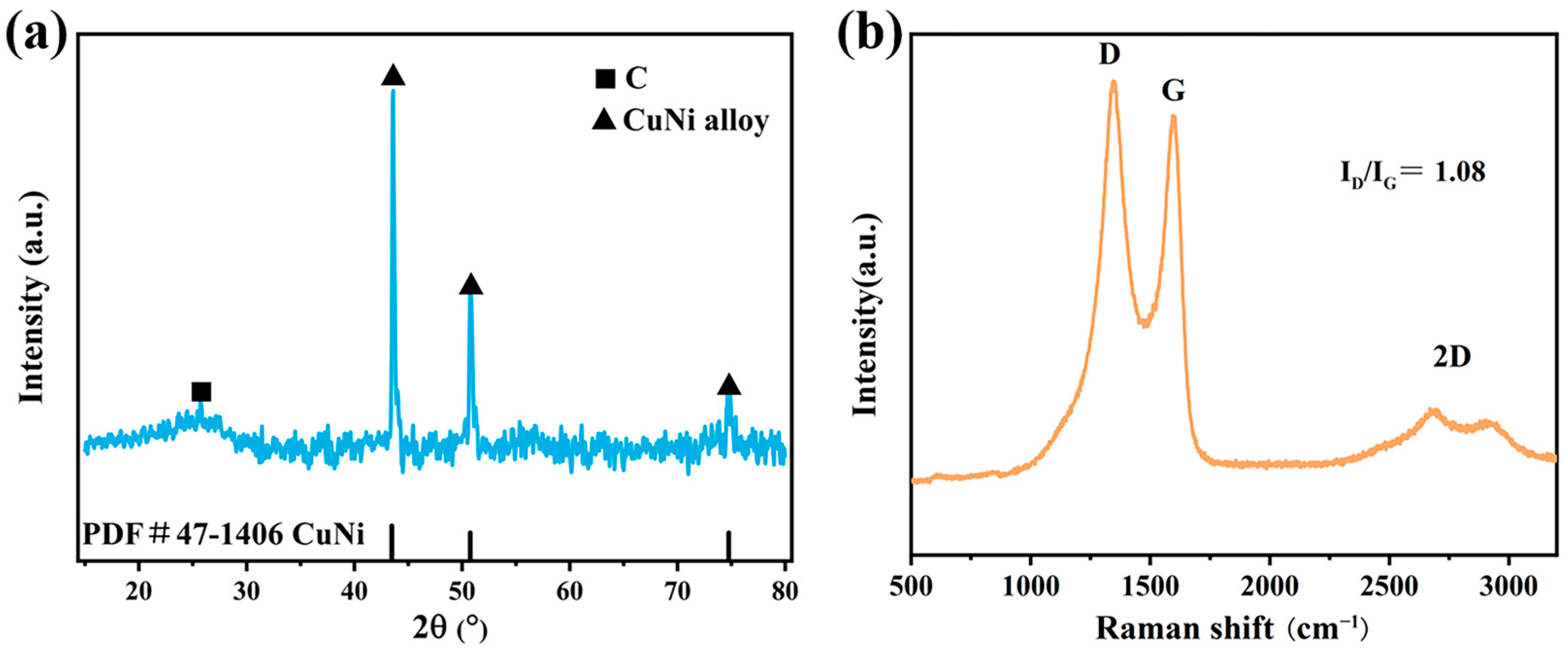
In the hydrothermal co-deposition process, urea acts as a precipitant and reacts with Cu2+ and Ni2+ in a precipitation reaction to generate Cu(OH)2 and Ni(OH)2, which are filled in the C/C precast body. At elevated temperatures, Cu(OH)2 and Ni(OH)2 decompose thermally into CuO and NiO. During subsequent heat treatment, these oxides undergo carbothermal reduction with hydrothermal carbon deposited in the C/C preform. The results show that Cu and Ni form CuNi alloys by infinite solid solution. Figure 2a shows the XRD pattern of C/C-CuNi composites prepared at a heat treatment temperature of 1200 °C. The diffraction peak at 26° is the physical phase of standard graphitized carbon [33], and the diffraction peaks at 43.6°, 50.8°, and 74.6° all correspond to the physical phase of Cu3.8Ni, a result that is attributed to the infinite impermissibility of copper and nickel. The graphitization of the composites was analyzed using Raman spectroscopy as shown in Figure 2b. The G peak near 1580 cm−1 is attributed to the E2g vibrational mode of the sp2 bonded carbon atoms in the 2D hexagonal lattice. The D peak near 1350 cm−1 corresponds to the vibration of the sp3 carbon atoms, which is used to characterize the defect sites or edges in the carbon structure [34,35]. The D/G intensity ratio increases with both the degree of structural disorder and the average size of sp2 domains [36,37]. Therefore, the ID/IG ratio is widely used to quantify defects in carbon materials: A higher value indicates greater defect density, while a lower value signifies a more graphitic atomic arrangement and a higher degree of graphitization. The 2D peak near 2700 cm−1, a double phonon resonance second-order Raman peak, is used to characterize the way of interlayer stacking of the carbon atoms in the graphene samples [38].
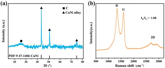
Figure 2.
(a) XRD patterns; (b) Raman spectra.
The microscopic morphology and structure of the composites are further characterized using scanning electron microscopy (secondary electron imaging). At low magnification, the surface of the material is dense, and the molten CuNi alloy at 1200 °C fills the pores between the fibers, increasing the density of the composite (Figure 3a). However, more tiny pores with a diameter of about 5 μm are observed on the surface of the material, which is due to the gas generated during the carbon thermal reduction process overflowing from the surface of the composite material and forming pores, and such tiny pores do not affect the overall structure and properties of the material (Figure 3b). To further observe the filling of the fibers in the matrix, under high magnification electron microscopy, it can be seen that the carbon fibers have been completely covered by the filled matrix, with no bare carbon fibers, and the carbon fibers have a stronger combination with the matrix, with strong interfacial bonding ability (Figure 3c). The distribution of C, Cu, and Ni phases in the composites is thoroughly analyzed in conjunction with EDS spectroscopy, from which it can be seen that the surface of the carbon fibers is encapsulated with numerous hydrothermally co-deposited carbon and accompanied by large metallic lamellae. It can be seen in the spectra that the bright metal particles correspond to the CuNi alloy, indicating the formation of a CuNi solid solution. The nickel element is uniformly distributed in the matrix, accompanied by a small enrichment of metallic nickel, and a high content of Cu element occurs with the phenomenon of Cu-Ni bias aggregation.
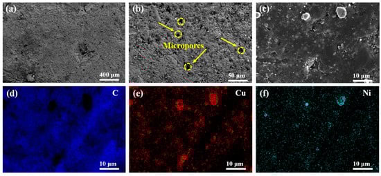
Figure 3.
(a–c) Microscopic morphology of C/C-CuNi composite; (d–f) EDS mapping.
3.2. Structural Changes Analysis of C/C-CuNi Composite After Arc Discharge
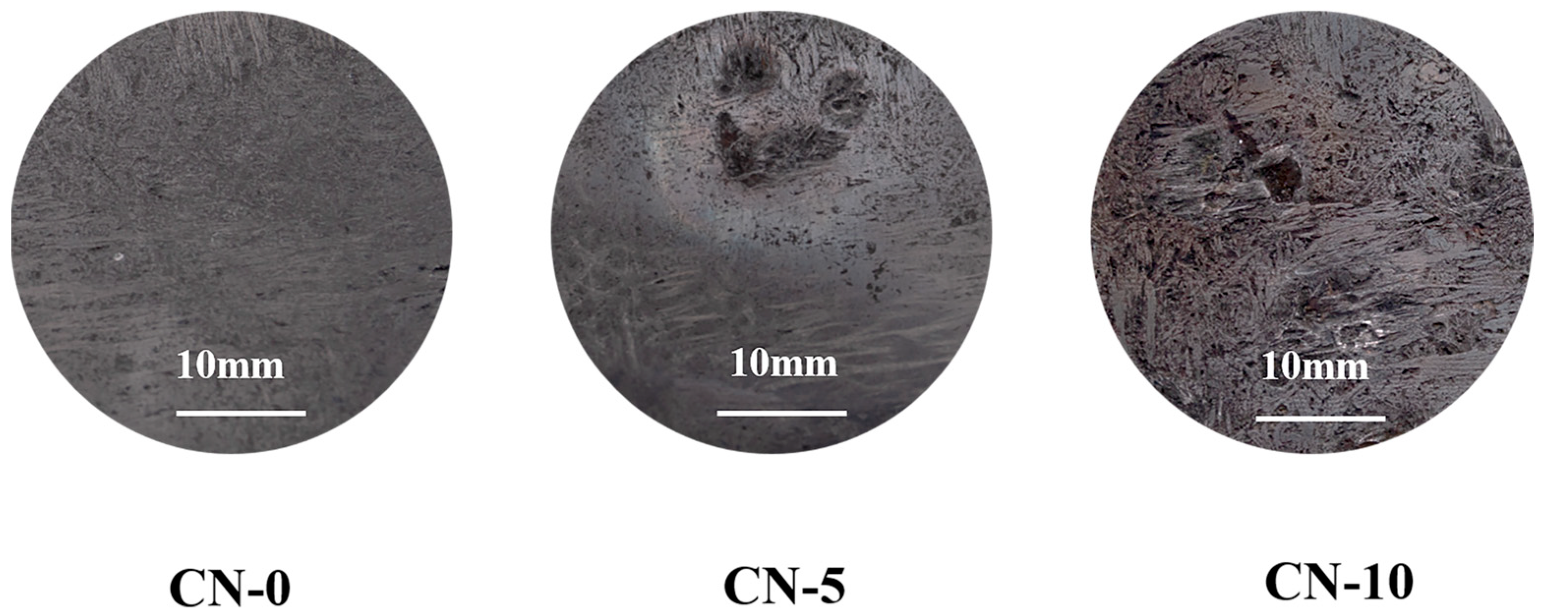
Figure 4 demonstrates the macroscopic morphology of the material surface of the C/C-CuNi composites before and after arc discharge. The untreated CN-0 material exhibits a smooth surface and a compact structure. After undergoing low-frequency arc discharge treatment, the surface of the CN-5 material becomes uneven due to arc-induced erosion, forming localized erosion points and ablation craters. Following multiple arc discharge cycles, the dense matrix of the CN-10 material becomes visibly damaged, exposing internal carbon fibers and showing slight detachment. An increase in arc discharge density leads to the formation of additional ablation craters and open pores on the material surface. Under high-density arc discharge conditions, arc contact points propagate across the material surface. As the discharge covers the surface, stable arc combustion causes surface softening. Concurrently, the matrix undergoes delamination and detachment under intensified arc density, resulting in the formation of interconnected pores and ablation craters [39].
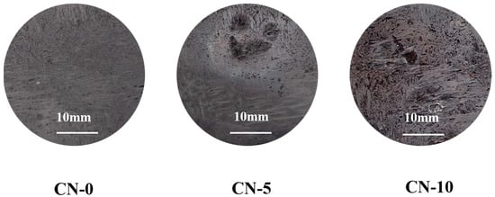
Figure 4.
Macroscopic surface morphology of C/C-CuNi composites before and after arc discharge.
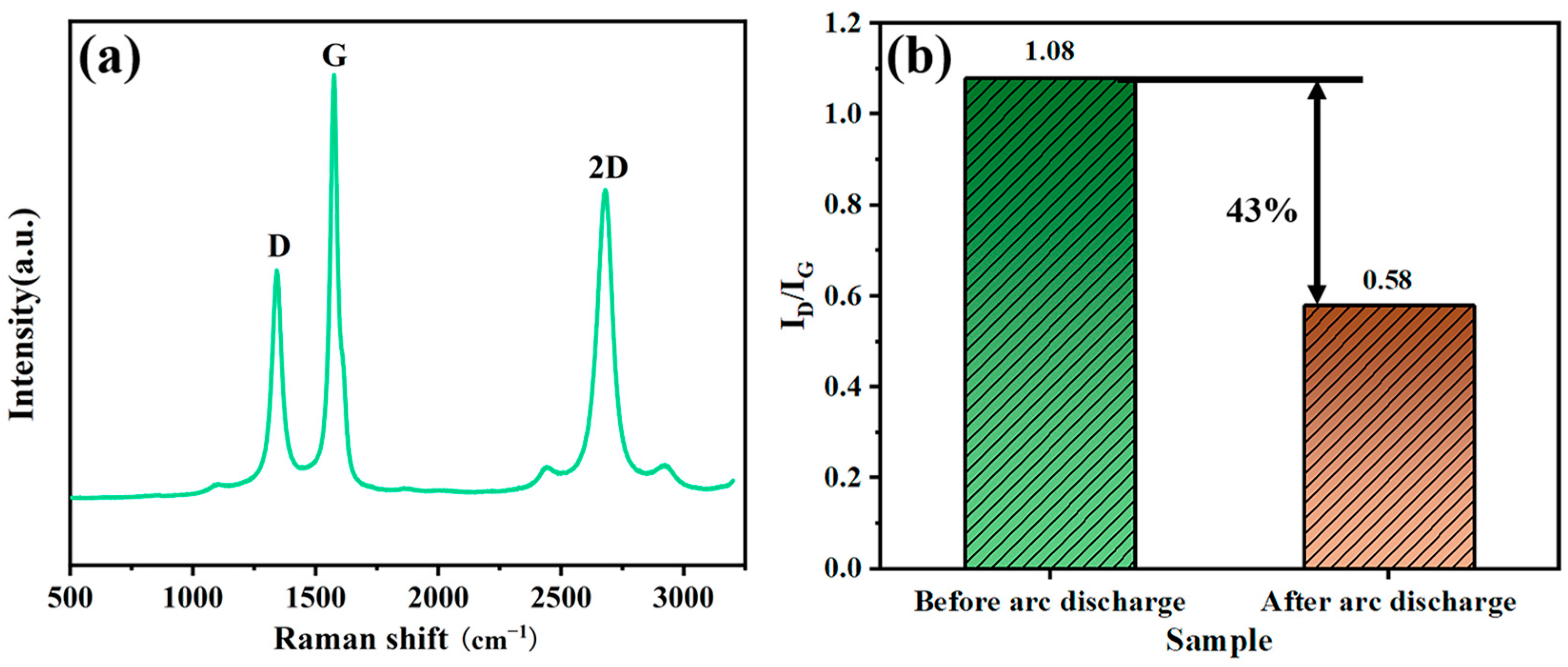
In comparison, the Raman spectra of CN-10 after arc discharge observed a substantial increase in the intensity of the G and 2D peaks representing the degree of ordering of the carbon elements, indicating that after the transient spark discharge, the surface temperature of the material increased, and the catalytic graphitization of Ni became stronger [40], catalyzing a larger number of graphene structures at the erosion, as shown in Figure 5a. The ID/IG values of CN-0 and CN-10 before and after arc discharge are presented in Figure 5b. The ID/IG values are used to evaluate the effective microcrystalline size in the graphitic plane (La) direction [41]. When the degree of order increases, the ratio of the peak intensity of ID/IG indicates the degree of graphitization, and the ID/IG value of the composites decreased significantly from 1.08 to 0.58 after arc discharge, a decrease of 43.6%, which indicates that the arc discharge provided enough energy to change the microcrystalline structure, which led to an increase in the degree of graphitization in the crystalline region of the arc discharge, promoting the growth of graphite structure and the graphite of the carbon atom crystal domain structure increased [42].
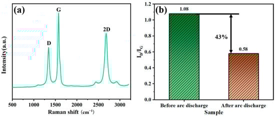
Figure 5.
Raman diagram of C/C-CuNi composite: (a) after arc discharge; (b) ID/IG value of C/C-CuNi composite before and after arc discharge.
To investigate the effect of arc discharge on the structure of C/C-CuNi composites, the morphological changes of CN-10 are analyzed, as shown in Figure 6. After experiencing a higher density of arc discharge, the composite surface formed obvious circular ablation craters with a diameter of about 1 mm, and there is obvious material loss on the surface of the ablation craters, while there is an open pore structure around the weak of the ablation craters, which resulted in a significant increase in the roughness of the surface of the composite material, as shown in Figure 6a. From Figure 6b, it can be observed that after experiencing the arc discharge, the carbon fibers are broken under the action of the arc in the form of a pinprick, which makes a large area of carbon fibers exposed on the surface. Due to the electric excitation and high-temperature effect, a large amount of matrix at the arc ablation is lost, failing the bonding between the carbon fibers and the matrix, and the strength of the material is reduced. A honeycomb-like morphology is observed inside the discharged matrix, with round metal particles attached to both the surface and the inner wall, with an average size of around 50~100 nm. Notably, a typical carbon nanotube structure is found inside the matrix, as shown in Figure 6d.
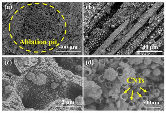
Figure 6.
Micromorphology of C/C-CuNi composite after arc discharge: (a,b) low magnification images; (c,d) high magnification images.
The diameter of the carbon nanotubes catalyzed by the inter-particle catalytic growth of metal particles was in the range of 100~150 nm, and the structure of the carbon nanotubes is a complete graphene network, which indicated that the microstructure of the carbon material is transformed by the growth of the carbon nanotubes inside the composite material by the electric arc beam and the high temperature in the continuous discharge condition [43]. This is consistent with the above Raman analysis results.
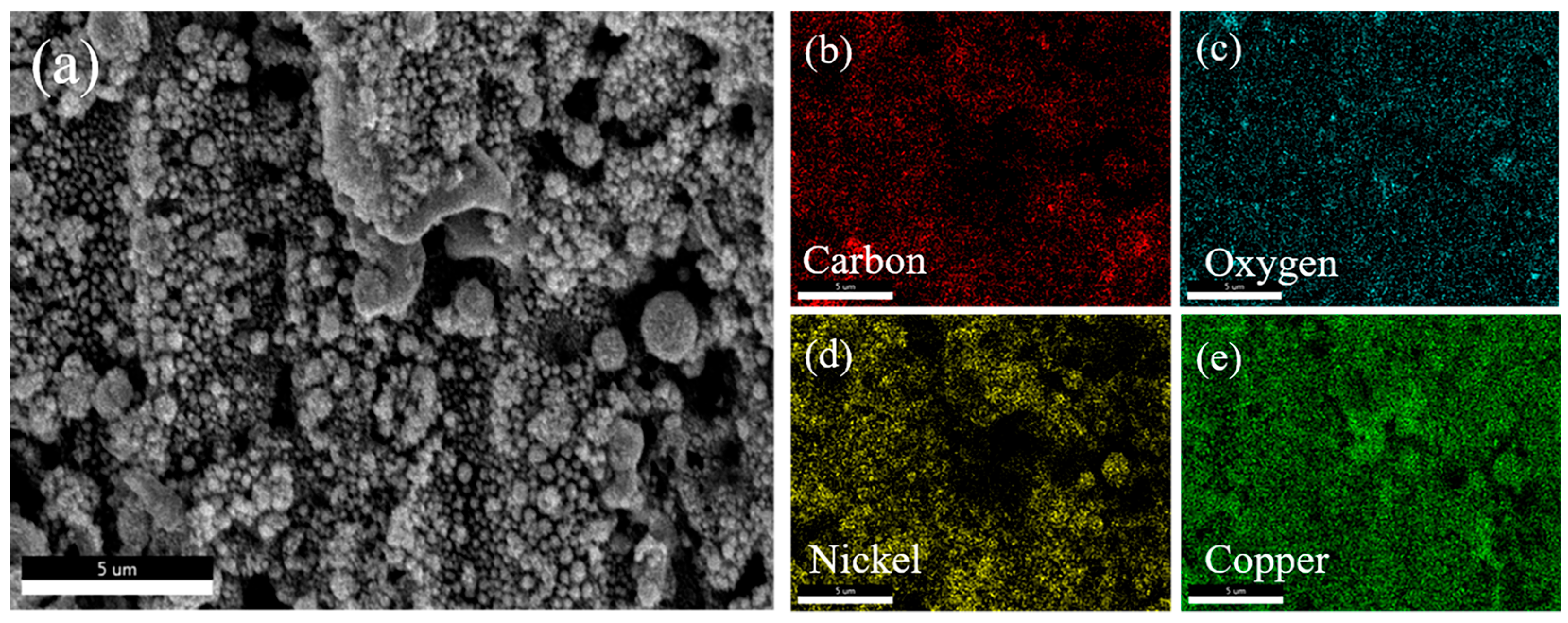
The arc discharge region of the C/C-CuNi composite was analyzed by EDS, as shown in Figure 7. It can be observed that these round particles of different sizes are the metal oxides of Cu and Ni. The sputtered metal at the instant of arc discharge and the alloy inside the composite are oxidized on the surface of the composite by the high voltage and high temperature. The active part of carbon is easily oxidized by the thermal effect of the arc, which inevitably leads to particle loosening or agglomeration coking. The higher the arc density, the higher the oxidation of the carbon material, which contributes to the formation of open pore structures on the wear surface in friction.
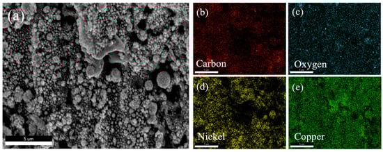
Figure 7.
Element distribution on the surface of C/C-CuNi composite after arc discharge: (a) SEM image; (b–e) element mapping.
The transformation of the internal carbon structure of the composites after arc discharge is thoroughly analyzed using transmission electron microscopy (a small amount of surface powder of the sample was taken and mixed with ethanol and sonicated for 10 min for uniform dispersion. After allowing the solution to stand, the upper layer of clear liquid was taken and added dropwise to the carbon support film, dried for use). The typical graphene structure observed in Figure 8a confirms that the C/C-CuNi composites catalyze the graphene structure inside the material under arc discharge, the original carbon structure of the material is transformed, and the graphitization is enhanced, which is in agreement with the previous raman spectrum analysis. During the discharge process, the microcrystals in the arc erosion region acquire higher crystallinity due to the high temperature induced by the arc instant, which directly leads to the change of carbon organization characteristics. Secondly, due to the existence of different degrees of thermal expansion of the carbon layer under high temperature and stress, the crystallization state of the carbon layer is changed and rearranged, thus generating a graphene and carbon nanotube structure that is different from the original carbon structure [44]. The high temperatures generated at the instant of the arc discharge cause the material surface to overheat and oxidize to produce the associated metal oxides. Whereas, in Figure 8c,d, it can be observed that the oxidation of the composite material caused by the arc discharge transforms the copper-nickel alloy into its associated oxides with a crystalline spacing of 0.241 nm and 0.297 nm corresponds to the (111) crystalline surface of nickel oxide and the (110) crystalline surface of cuprous oxide, respectively.
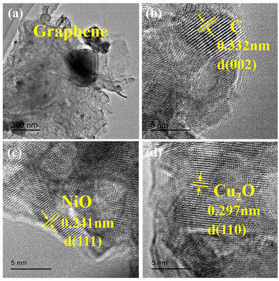
Figure 8.
TEM diagram of C/C-CuNi composite after arc discharge: (a) graphene structure; (b) lattice striations in the C Substrate; (c) the lattice striations of NiO; (d) the lattice striations of Cu2O.
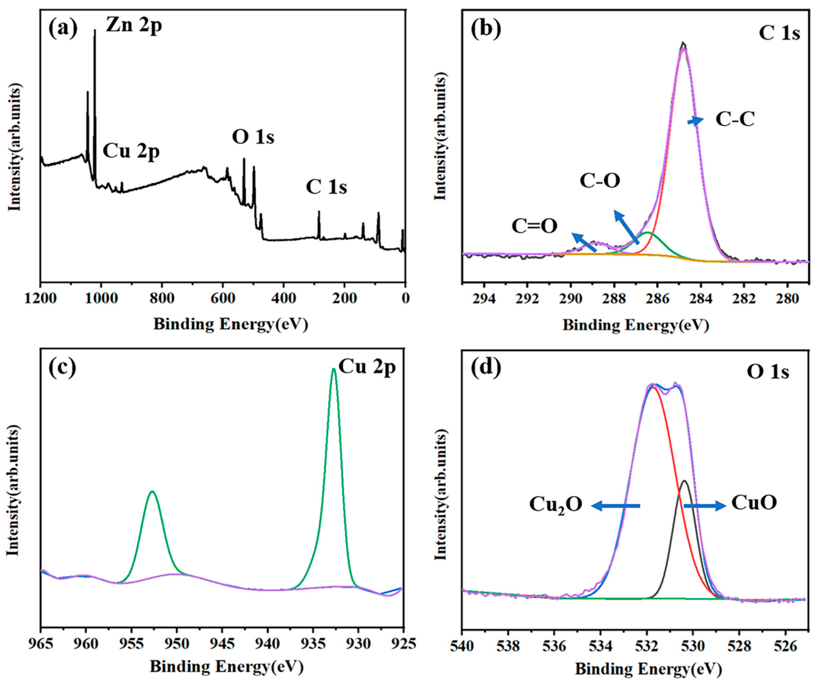
X-ray photoelectron spectroscopy is used to analyze the surface chemical composition and chemical states of the elements in the composites after arc discharge. Based on the results of Figure 9a elemental full spectra, it can be seen that carbon, oxygen, copper, and zinc elements are present in the composites after arc discharge. The presence of zinc element is because the metal wire involved in the arc discharge is a Cu/Zn alloy, which is deposited on the surface of the composite by sputtering. In Figure 9b, the presence of C-C (284.7 eV), C-O (284.83 eV), C=O (287.6 eV) is confirmed from the in-depth analysis of the high-resolution C 1s spectra [45], and due to the extremely high temperature of the surface of the composite material under the action of the arc discharge, the heat generated by the arc discharge directly leads to the matrix detachment and thermal damage, which results in an acceleration of the oxidation of the carbon elements on the contact surface. Figure 9c shows the high-resolution spectrum of Cu 2p, and Cu 2p1/2 and Cu 2p3/2 correspond to Cu2O orbitals. The two characteristic peaks appearing at 529.2 eV and 530.5 eV correspond to the two orbitals of CuO and Cu2O [46], which further confirms the presence of copper oxides in the composite material after arc discharge.
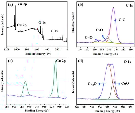
Figure 9.
(a) XPS full spectrum; (b) C 1s; (c) Cu 2p; (d) O 1s of C/C-CuNi after arc discharge.
3.3. Friction Behavior and Mechanism Analysis of C/C-CuNi Composites After Arc Discharge
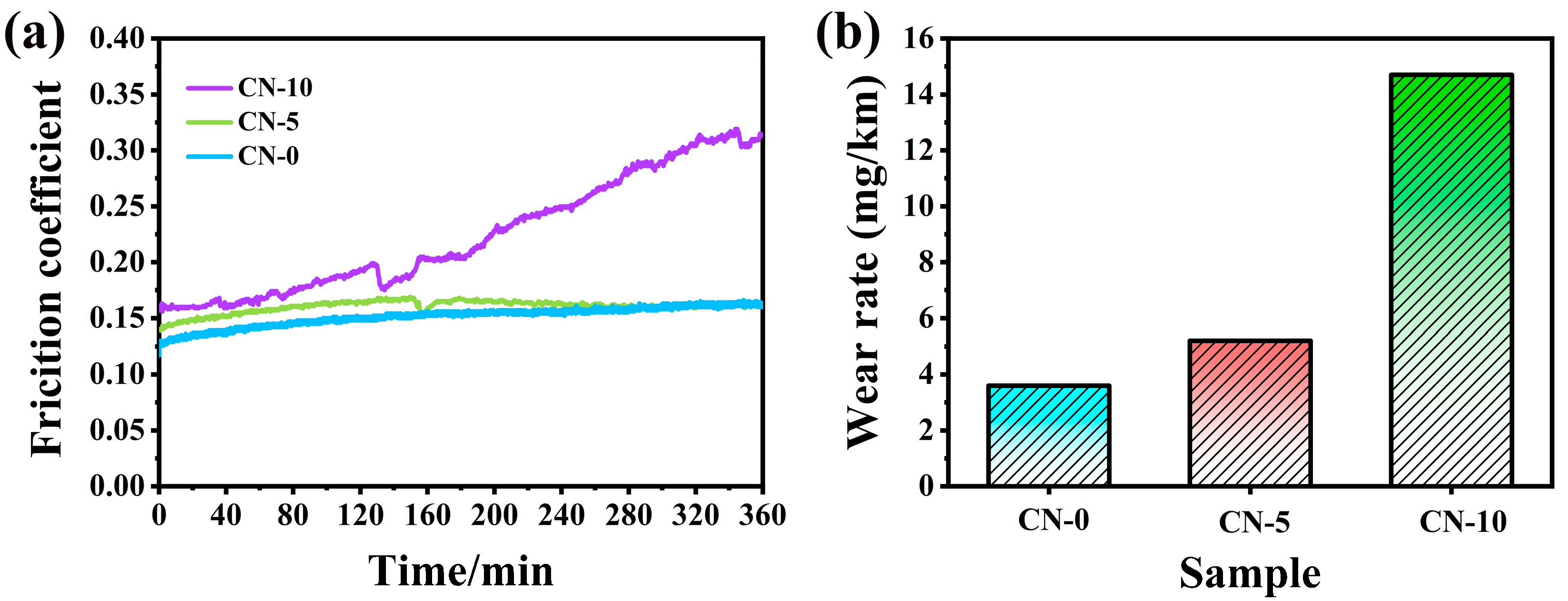
Figure 10 shows the friction profiles of C/C-CuNi composites after loading with 100 N at different arc discharge densities. The friction coefficient of the CN-0 sample without arc discharge did not fluctuate greatly during the 360 min friction experiment (Figure 10a). Under limited arc discharge conditions, the CN-5 sample demonstrates an initially stable friction coefficient. During the first 140 min, a gradual increase in friction coefficient is observed, attributed to progressive frictional wear increasing surface roughness. Beyond this duration, the coefficient starts declining as the composite′s surface layer becomes depleted through continuous abrasion. This wear process eventually exposes the arc-ablated subsurface region where graphitic carbon domains are distributed. The contact between these lubricating graphitic carbon phases and the counterpart surface establishes effective friction reduction. After prolonged sliding, the system maintains stable tribological performance with a steady-state friction coefficient stabilized around 0.16. When the density of arc discharge is increased, the friction coefficient of the CN-10 sample showed a constant fluctuation, and the friction coefficient continued to increase, rising to 0.27 after 360 min of friction. It is worth noting that in the first 130 min, the graphene structure is excited inside the material due to a large number of arc discharges, and graphene is involved in the friction, and the large increase in the coefficient of friction in the later stage is due to a large number of arc discharges as well as the high loading that destroys the material′s intrinsic structure after a long period of friction, and the friction surface is subjected to a combination of two forms of heat during wear: frictional heat and joule heat [47,48], which will increase the temperature of the friction surface, leading to oxidation of the carbon material and graphene, which reduces the wear performance of the composite.
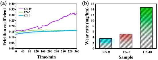
Figure 10.
(a) Friction curves; (b) Wear rate of C/C-CuNi loaded with 100 N at different arc discharges.
Comparative analysis of wear rates across composites subjected to varying arc discharge densities reveals distinct performance differences. The results indicate wear rates of 3.6 mg/km (CN-0), 5.2 mg/km (CN-5), and 14.7 mg/km (CN-10), with CN-10 exhibiting a significantly elevated wear rate compared to its counterparts, as illustrated in Figure 10b.
The reason for this is that as the arc discharge density increases, this enhances the effect of arc ablation and leads to an increased wear rate. The oxidation of C/C-CuNi composites in rough contact will be accelerated due to the very high surface temperature and the collapse of the composite structure upon increasing the arc discharge density. This is mainly attributed to the Joule-heat-induced increase in the contact surface temperature of the C/C-CuNi composite and the high-temperature oxidation that occurs instantaneously from the arc discharge, which leads to overheating of the wear surface. As a result, the wear will become severe when the temperature in the contact zone exceeds the threshold temperature for C-C bond breaking and surface oxide layer exfoliation at the contact interface. At the same time, the carbon material in the wear region is more susceptible to high-temperature sublimation.
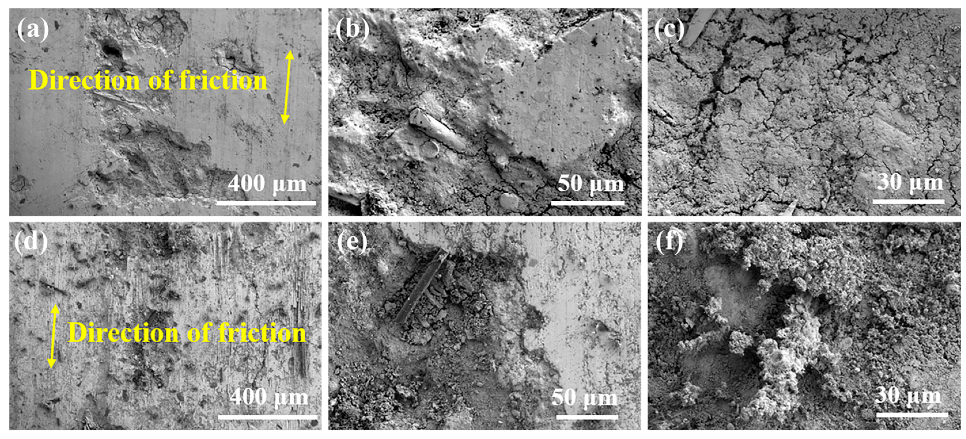
To investigate the effect of arc ablation density on the friction properties of C/C-CuNi composites, SEM morphology analysis of the abrasion marks and chips is carried out, as shown in Figure 11. The arrows indicate the direction of relative motion of the composite/friction pair. Figure 11a,d clearly shows numerous ablation arc craters and oxidized wear regions with open pore structures along the sliding direction, and the surface roughness of the high-arc-discharged composite is significantly higher than that of the low-arc-discharged composite. At low arc densities, which are at the same level as the unabraded samples, the composites show some self-healing ability. In addition, an increase in arc density leads to more ablation arc pits and openings, a gradual decrease in the size of the abrasive chips adhering to the abrasive marks, and an increase in the number of wear particles due to enhanced oxidation (Figure 11b,e).
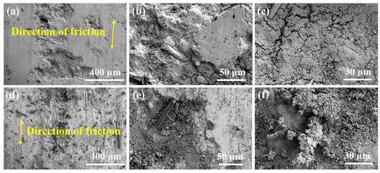
Figure 11.
SEM of friction surface of C/C-CuNi composites after arc discharge: (a–c) CN-5; (d–f) CN-10.
Under the action of arc discharge, the wear surfaces of composites exhibit thermal expansion, fatigue spalling, and arc erosion, which promotes the generation of small abrasive chips. In addition, the active parts of carbon on the wear surface are easily oxidized by the thermal effects of the arc, which leads to particle loosening or agglomeration coking. The higher the arc density, the more the carbon material is oxidized, which contributes to the formation of open pore structures in the wear scar region. According to these observations, under the combined effect of arc and sliding friction, a typical wear mark region consists of arc ablation marks, ablation pits, and non-exfoliated abrasive debris. The results indicate that the tribological behavior under continuous arc conditions is a result of the interaction of arc ablative and oxidative wear and fatigue spalling.
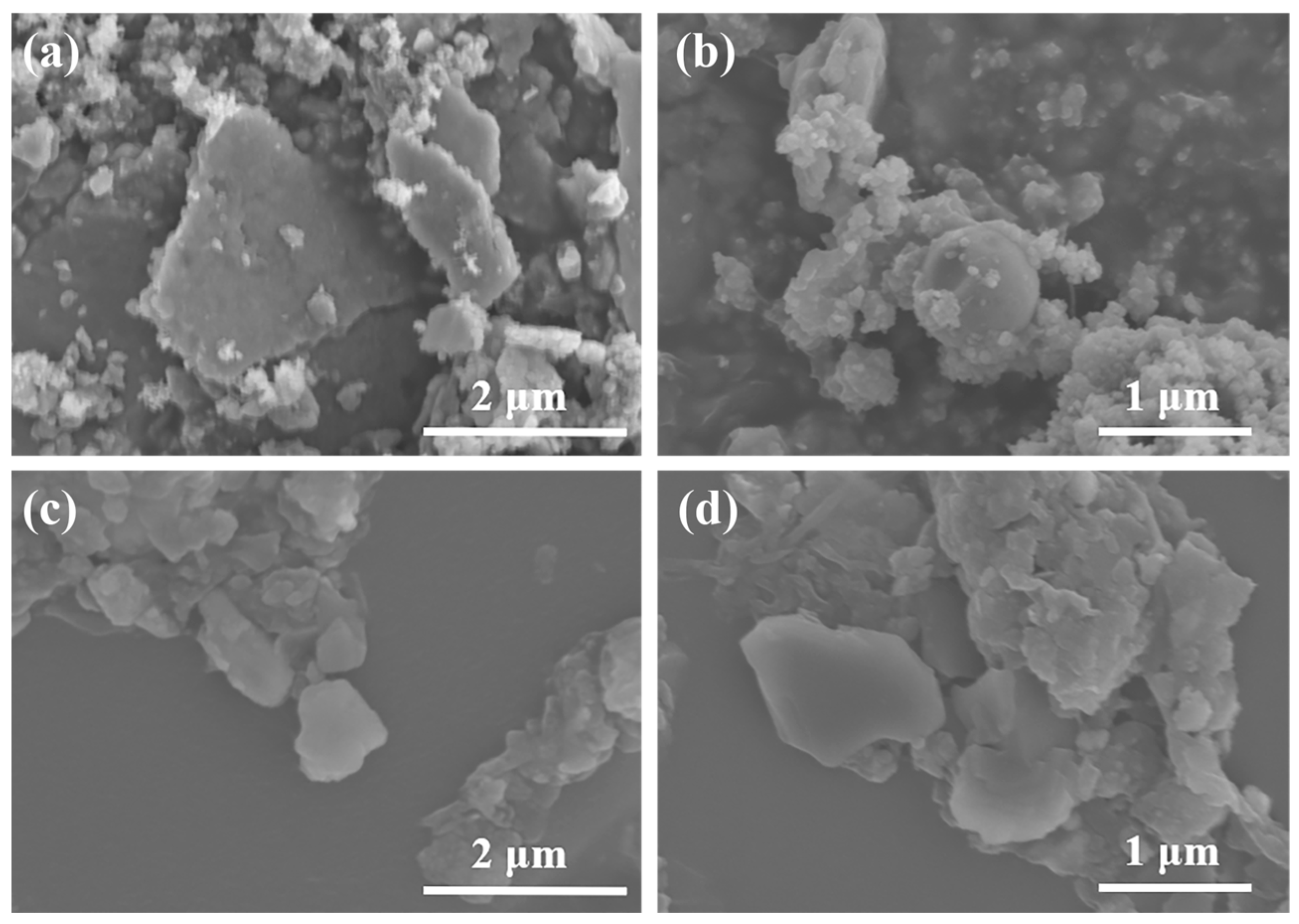
The abrasive debris on the wear surface plays a key role in the study of the friction process. Figure 12 shows the SEM image of C/C-CuNi composites wear chips after arc discharge. When the arc discharge density is small, the abrasive flakes appear as typical irregular flakes and are accompanied by fewer spherical particles (Figure 12a,b). However, when the arc discharge density increases, the number of abrasive particles gradually increases, the size of the flakes decreases, and they agglomerate into larger lumps (Figure 12c,d). This is due to the shear fracture and grinding of micro-convex bodies on the composite wear marks during the wear process, which directly leads to the dislodging of wear particles from the contact interface. As the arc discharge density increases, the flaky wear chips gradually transform into granular wear chips, which is a typical feature of abrasive wear.

Figure 12.
SEM of wear debris of C/C-CuNi composites after arc discharge: (a,b) CN-5; (c,d) CN-10.
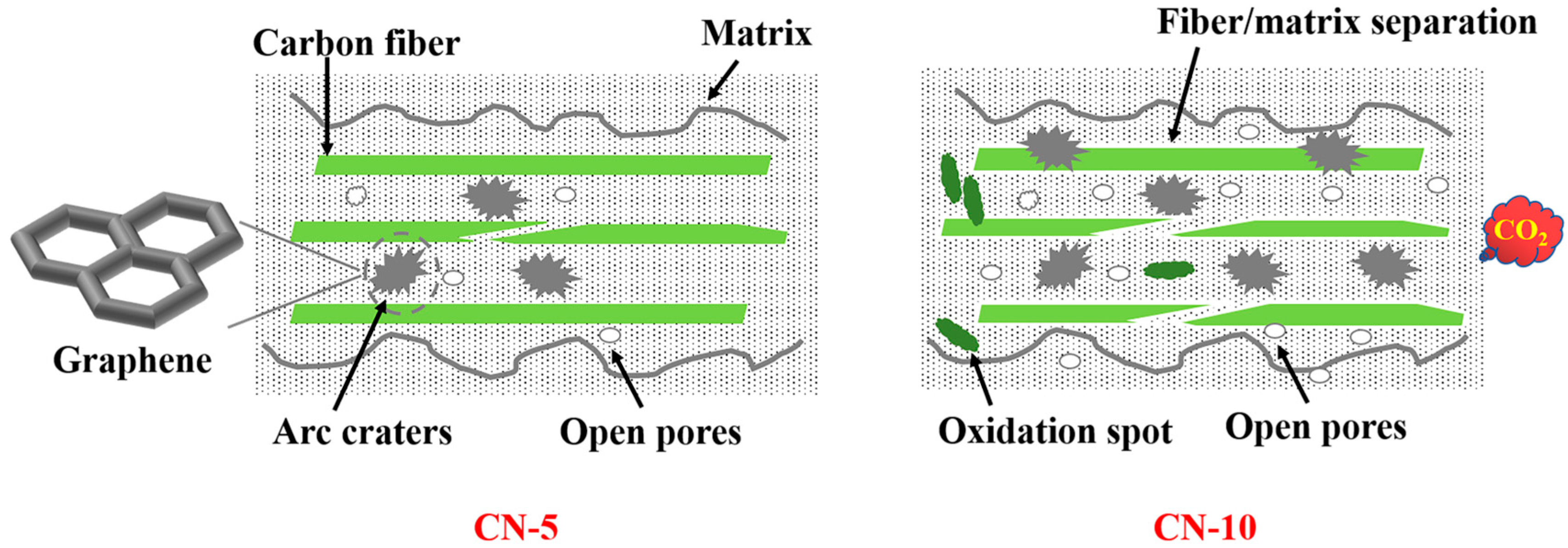
Combined with the above analysis, we summarize the friction mechanism of C/C-CuNi composites under the action of arc discharge (Figure 13). When experiencing arc discharge, the area around the arc is easily oxidized and gasified by the arc caused by continuous electrical excitation, which leads to the collapse of the internal structure of the C/C-CuNi composites, separation of the matrix from the fibers, and the large exfoliated abrasive debris transforming the friction into abrasive wear, and the wear surface accelerates the oxidization process of the carbon material due to overheating under the dual effect of frictional heat and Joule heat. High arc erosion leads to material deterioration and accelerates the damage failure of the material in friction. Therefore, it is concluded that the wear mechanisms of C/C-CuNi composites under continuous arc conditions are arc erosion wear, oxidative wear, abrasive wear, and adhesive wear.

Figure 13.
Friction mechanism of C/C-CuNi composites after arc discharge.
4. Conclusions
Based on our previous research, under pure mechanical conditions, wear primarily manifests as low-stress abrasive wear, oxidative wear, and mild adhesive wear. Under low-density arc discharge conditions, the arc only creates limited pores on the composite surface without significantly compromising the structural integrity of the matrix. The graphene structures generated by arc discharge effectively reduce friction through self-lubrication. However, as arc density increases, high-frequency arc discharge severely damages the matrix, causing progressive surface peeling and the formation of extensive pits and cavities. Under the combined effects of frictional heat and Joule heating, matrix oxidation occurs, accompanied by fiber-matrix interfacial separation, ultimately leading to internal structural collapse. High-density arc erosion induces material failure and rapid wear rate escalation. Therefore, the wear mechanism of C/C-CuNi composites under arc ablation is predominantly characterized by arc erosive wear caused by continuous arc discharge-induced matrix oxidation failure.
Author Contributions
Conceptualization, Y.Z. and X.L.; validation, X.L. and H.W.; formal analysis, J.L. and D.Z.; writing—original draft preparation, X.L.; writing—review and editing, H.O. All authors have read and agreed to the published version of the manuscript.
Funding
This research was supported by the National Nature Science Foundation of China (Grant No. 52173299, 52372087).
Data Availability Statement
All original data from the study have been fully included in the article and further inquiries can be directed to the corresponding author.
Conflicts of Interest
The authors declare no conflicts of interest.
References
- Xiao, S.; Luo, Y.; Wu, J.; Zhang, C.; Rao, Y.; Wu, G.; Deng, Z.; Sykulski, J.K. An Investigation into the Characteristics of a Novel Rotatable Pantograph Catenary System for High-Speed Trains. J. Electr. Eng. Technol. 2021, 16, 1721–1730. [Google Scholar] [CrossRef]
- Zhang, W.; Shen, Z.; Zeng, J. Study on dynamics of coupled systems in high-speed trains. Veh. Syst. Dyn. 2013, 51, 966–1016. [Google Scholar] [CrossRef]
- Wang, Y.A.; Li, J.X.; Yan, Y.; Qiao, L.J. Effect of electrical current on tribological behavior of copper-impregnated metallized carbon against a Cu–Cr–Zr alloy. Tribol. Int. 2012, 50, 26–34. [Google Scholar] [CrossRef]
- Kubo, S.K.K. Effect of arc discharge on wear rate of Cu-impregnated carbon strip in unlubricated sliding against Cu trolley under electric current. Wear 1998, 216, 172–178. [Google Scholar] [CrossRef]
- Xianzh, X.; Chuanjun, T.U.; Gang, C.; Lianpu, D.; Xilun, J. Research Progress on Tribological Behavior with Current and Microstructures of Worn Surfaces of Pantograph Contact Strip. Mater. Rev. 2014, 28, 20–25. [Google Scholar]
- Ding, T.; Chen, G.X.; Wang, X.; Zhu, M.H.; Zhang, W.H.; Zhou, W.X. Friction and wear behavior of pure carbon strip sliding against copper contact wire under AC passage at high speeds. Tribol. Int. 2011, 44, 437–444. [Google Scholar] [CrossRef]
- Deng, C.; Yin, J.; Zhang, H.; Xiong, X.; Wang, P.; Sun, M. The tribological properties of Cf/Cu/C composites under applied electric current. Tribol. Int. 2017, 116, 84–94. [Google Scholar] [CrossRef]
- Xu, E.; Huang, J.; Li, Y.; Zhu, Z.; Cheng, M.; Li, D.; Zhong, H.; Liu, J.; Jiang, Y. Graphite cluster/copper-based powder metallurgy composite for pantograph slider with well-behaved mechanical and wear performance. Powder Technol. 2019, 344, 551–560. [Google Scholar] [CrossRef]
- Kim, Y.; Sathish Kumar, S.K.; Park, Y.; Kwon, H.; Kim, C.-G. High-velocity impact onto a high-frictional fabric treated with adhesive spray coating and shear thickening fluid impregnation. Compos. Part B Eng. 2020, 185, 107742. [Google Scholar] [CrossRef]
- Zhang, G.; Liu, Y.; Guo, F.; Liu, X.; Wang, Y. Friction Characteristics of Impregnated and Non-Impregnated Graphite against Cemented Carbide under Water Lubrication. J. Mater. Sci. Technol. 2017, 33, 1203–1209. [Google Scholar] [CrossRef]
- Yang, H.; Hu, B.; Liu, Y.; Cui, X.; Jiang, G. Influence of reciprocating distance on the delamination wear of the carbon strip in pantograph-catenary system at high sliding-speed with strong electrical current. Eng. Fail. Anal. 2019, 104, 887–897. [Google Scholar] [CrossRef]
- Bucca, G.; Collina, A. Electromechanical interaction between carbon-based pantograph strip and copper contact wire: A heuristic wear model. Tribol. Int. 2015, 92, 47–56. [Google Scholar] [CrossRef]
- Bucca, G.; Collina, A. A procedure for the wear prediction of collector strip and contact wire in pantograph-catenary system. Wear 2009, 266, 46–59. [Google Scholar] [CrossRef]
- Kubo, S.; Tsuchiya, H.; Kubota, Y. Application of Metal-Impregnated Carbon-Carbon Composite to Contact Strips of Pantograph of Electric Railway Vehicles. In Proceedings of the International Conference on Carbon 2008, Nagano, Japan, 13–18 July 2008. [Google Scholar]
- Zhou, W.Y.; Ran, L.P.; Peng, K.; Ge, Y.C.; Wu, H.; Yi, M.Z. Effect of Carbon/Carbon Preform Density on the Microstructure and Properties of Mo2C Interlayer-Modified Carbon/Carbon–Copper Composites for Sliding Contact Materials. Adv. Eng. Mater. 2015, 18, 277–283. [Google Scholar] [CrossRef]
- Yin, J.; Zhang, H.; Tan, C.; Xiong, X. Effect of heat treatment temperature on sliding wear behaviour of C/C-Cu composites under electric current. Wear 2014, 312, 91–95. [Google Scholar] [CrossRef]
- Yu, H.Y.; Shi, X.L.; Xu, F.M.; Tan, Y. Effect of infiltration copper or aluminium on flexural strength of C/C composite materials. Mater. Mech. Eng. 2007, 31, 61–64. [Google Scholar]
- Yin, J.; Zhang, H.; Xiong, X.; Tao, H.; Wang, P.; Deng, C. Influence of applied load on wear behavior of C/C-Cu composites under electric current. Prog. Nat. Sci. Mater. Int. 2017, 27, 192–196. [Google Scholar] [CrossRef]
- Ran, L.; Peng, K.; Yi, M.; Yang, L. Ablation property of a C/C–Cu composite prepared by pressureless infiltration. Mater. Lett. 2011, 65, 2076–2078. [Google Scholar] [CrossRef]
- Yin, J.; Zhang, H.; Bai, K.; Xiong, X.; Zhang, H.; Ma, D. Effect of carbon matrix on mechanical and tribological properties of Cf/Cu/C composites. Mater. Charact. 2020, 168, 110551. [Google Scholar] [CrossRef]
- Lloyd, J.C.; Neubauer, E.; Barcena, J.; Clegg, W.J. Effect of titanium on copper–titanium/carbon nanofibre composite materials. Compos. Sci. Technol. 2010, 70, 2284–2289. [Google Scholar] [CrossRef]
- Zhang, P.; Zhang, L.; Fu, K.; Wu, P.; Qu, X. Effects of Ni-Coated Graphite Flake on Braking Behavior of Cu-Based Brake Pads Applied in High-Speed Railway Trains. J. Tribol. 2019, 141, 081301. [Google Scholar] [CrossRef]
- Zhao, H.; Liu, L.; Hu, W.; Shen, B. Friction and wear behavior of Ni–graphite composites prepared by electroforming. Mater. Des. 2007, 28, 1374–1378. [Google Scholar] [CrossRef]
- Liao, Q.; Wei, W.; Zuo, H.; Li, X.; Yang, Z.; Xiao, S.; Wu, G. Interfacial bonding enhancement and properties improvement of carbon/copper composites based on nickel doping. Compos. Interfaces 2020, 28, 637–649. [Google Scholar] [CrossRef]
- Ouyang, H.; Ma, Y.; Gong, Q.; Li, C.; Huang, J.; Xu, Z.; Wei, B. Tailoring porous structure and graphitic degree of seaweed-derived carbons for high-rate performance lithium-ion batteries. J. Alloys Compd. 2020, 823, 153862. [Google Scholar] [CrossRef]
- Ouyang, H.; Wang, P.; Li, C.; Gao, R.; Shen, T.; Li, Y. Effect of humidity on the friction and wear behavior of C/C-CuNi composites. Diam. Relat. Mater. 2024, 146, 111144. [Google Scholar] [CrossRef]
- Weng, Y.; Yang, X.; Chen, F.; Zhang, X.; Shi, A.; Yan, J.; Huang, Q. Effect of CVI SiC content on ablation and mechanism of C/C-SiC-ZrC-Cu composites. Ceram. Int. 2022, 48, 7937–7950. [Google Scholar] [CrossRef]
- Wang, S.; Yin, J.; Xiefeng, M.; Tang, L.; Xiong, X.; Zhang, H.; Wen, Q.; Ma, D.; Zuo, J. Microstructure and ablation behaviour of C/C-SiC-ZrC-Cu composites prepared by reactive melt infiltration. Mater. Today Commun. 2024, 38, 108389. [Google Scholar] [CrossRef]
- Dong, Z.; Liu, B.; Hu, D.; Fu, Q. Low-temperature preparation of C/C-W-Cu composites with enhanced particle impact and ablation resistance. J. Alloys Compd. 2025, 1010, 177605. [Google Scholar] [CrossRef]
- Yuan, H.; Wang, C.; Zhang, S.; Lin, X. Effect of surface modification on carbon fiber and its reinforced phenolic matrix composite. Appl. Surf. Sci. 2012, 259, 288–293. [Google Scholar] [CrossRef]
- Cui, L.; Luo, R.; Wang, L.; Luo, H.; Deng, C. Novel copper-impregnated carbon strip for sliding contact materials. J. Alloys Compd. 2018, 735, 1846–1853. [Google Scholar] [CrossRef]
- Li, C.; Li, G.; Ouyang, H.; Huang, J.; Hou, X. Microstructure and properties of C/C–ZrC composites prepared by hydrothermal deposition combined with carbothermal reduction. J. Alloys Compd. 2018, 741, 323–330. [Google Scholar] [CrossRef]
- Zhai, D.; Du, H.; Li, B.; Zhu, Y.; Kang, F. Porous graphitic carbons prepared by combining chemical activation with catalytic graphitization. Carbon 2011, 49, 725–729. [Google Scholar] [CrossRef]
- Malard, L.M.; Pimenta, M.A.; Dresselhaus, G.; Dresselhaus, M.S. Raman spectroscopy in graphene. Phys. Rep. 2009, 473, 51–87. [Google Scholar] [CrossRef]
- Guo, P.; Su, L.; Jia, S.; Ni, Z.; Dai, Z.; Guo, J.; Wang, X.; Peng, K.; Wang, H. Strong SiC@Carbon nanowire aerogel metamaterials for efficient electromagnetic interference shielding. Carbon 2024, 229, 119492. [Google Scholar] [CrossRef]
- Xue, C.; Yang, F.; Wang, E.; Feng, L.; Du, X.; Hao, X.; Li, X. Nanosized graphitic carbon with balanced micro/mesoporosity for robust supercapacitor with superior volumetric capacitance and cyclic performance. Electrochim. Acta 2018, 271, 406–416. [Google Scholar] [CrossRef]
- Zhang, Y.; Chen, L.; Meng, Y.; Xie, J.; Guo, Y.; Xiao, D. Lithium and sodium storage in highly ordered mesoporous nitrogen-doped carbons derived from honey. J. Power Sources 2016, 335, 20–30. [Google Scholar] [CrossRef]
- Zhao, L.; Zhao, X.; Burke, L.T.; Bennett, J.C.; Dunlap, R.A.; Obrovac, M.N. Voronoi-Tessellated Graphite Produced by Low-Temperature Catalytic Graphitization from Renewable Resources. ChemSusChem 2017, 10, 3409–3418. [Google Scholar] [CrossRef] [PubMed]
- Zhou, F.; Chen, X.; Liu, P. Arc ablation behavior and mechanism of copper matrix composites reinforced with CNTs and Al2O3 particles. Mater. Today Commun. 2025, 46, 112584. [Google Scholar] [CrossRef]
- Yudasaka, M.; Tasaka, K.; Kikuchi, R.; Ohki, Y.; Yoshimura, S.; Ota, E. Influence of chemical bond of carbon on Ni catalyzed graphitization. J. Appl. Phys. 1997, 81, 7623–7629. [Google Scholar] [CrossRef]
- Guizani, C.; Haddad, K.; Limousy, L.; Jeguirim, M. New insights on the structural evolution of biomass char upon pyrolysis as revealed by the Raman spectroscopy and elemental analysis. Carbon 2017, 119, 519–521. [Google Scholar] [CrossRef]
- Li, C.; Li, K.; Li, H.; Zhang, Y.; Liu, L.; Sun, C. Microstructure and thermal conductivity of carbon/carbon composites containing zirconium carbide. J. Mater. Sci. 2013, 48, 7568–7573. [Google Scholar] [CrossRef]
- Ribeiro, H.; Schnitzler, M.C.; da Silva, W.M.; Santos, A.P. Purification of carbon nanotubes produced by the electric arc-discharge method. Surf. Interfaces 2021, 26, 101389. [Google Scholar] [CrossRef]
- Mondal, S.; Datta, A. Correlating Negative Thermal Expansion and Thermal Conductivity in Two-dimensional Carbon-based Materials. Phys. Chem. Chem. Phys. 2024, 26, 29568–29576. [Google Scholar] [CrossRef]
- Tao, K.; Li, P.; Kang, L.; Li, X.; Zhou, Q.; Dong, L.; Liang, W. Facile and low-cost combustion-synthesized amorphous mesoporous NiO/carbon as high mass-loading pseudocapacitor materials. J. Power Sources 2015, 293, 23–32. [Google Scholar] [CrossRef]
- Xu, H.; Ye, T.; Zhang, X.; Lu, L.; Xiong, W.; Zhu, Y. Insights into the adsorption mechanism of N-thiourea-maleamic acid on chalcopyrite surface in the flotation separation of Cu-Mo sulfide ores. J. Mol. Liq. 2022, 350, 118554. [Google Scholar] [CrossRef]
- Wang, Y.; Zhang, M.; Wang, Y.; Zhang, G.; Lu, Z. Influence of currents on tribological behavior of diamond-like carbon films. Appl. Phys. A 2020, 126, 248. [Google Scholar] [CrossRef]
- Dai, H.-C.; Shen, F.; Li, Y.-H.; Ke, L.-L. Sliding Electrical Contact Model Considering Frictional and Joule Heating. Acta Mech. Solida Sin. 2024, 37, 823–836. [Google Scholar] [CrossRef]


Disclaimer/Publisher’s Note: The statements, opinions and data contained in all publications are solely those of the individual author(s) and contributor(s) and not of MDPI and/or the editor(s). MDPI and/or the editor(s) disclaim responsibility for any injury to people or property resulting from any ideas, methods, instructions or products referred to in the content. |
© 2025 by the authors. Licensee MDPI, Basel, Switzerland. This article is an open access article distributed under the terms and conditions of the Creative Commons Attribution (CC BY) license (https://creativecommons.org/licenses/by/4.0/).