Thermoplastic Labyrinth Seals Under Rub Impact: Deformation Leakage Mechanisms and High Efficiency Optimization
Abstract
1. Introduction
- (1)
- The development and implementation of a novel rub-impact test system specifically designed to quantify the dynamic interaction forces and resulting deformation between thermoplastic seal specimens and a rotating eccentric rotor.
- (2)
- A coupled numerical approach employing finite element analysis (FEA) to predict tooth deformation under rub-impact and computational fluid dynamics (CFD) to analyze the resulting leakage rates through the deformed geometries with rigorous validation of the FEA deformation model against experimental measurements.
- (3)
- The analysis and identification of key material-specific deformation mechanisms in different thermoplastics under rub-impact and their direct correlation with post-impact clearance and leakage.
- (4)
- The design and performance validation of two optimized inclined-tooth geometries, informed by the understanding of deformation and flow mechanisms, demonstrating significant leakage reduction under rub-impact conditions.
2. Experimental System
2.1. Design of the Rub-Impact Experimental System
- (1)
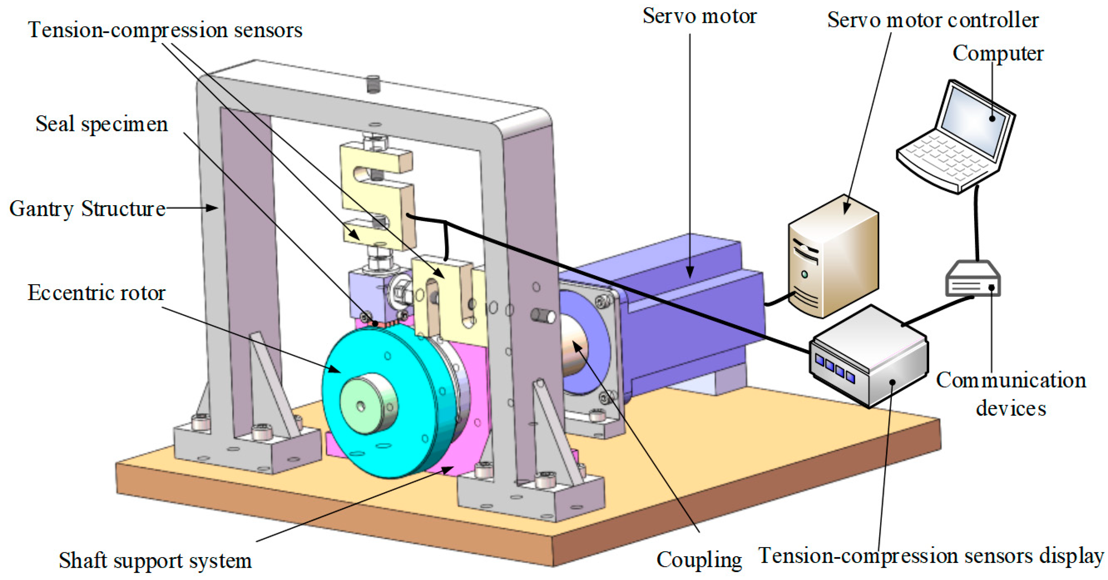
- Servo Motor
- (2)
- Bellows Flexible Coupling
- (3)
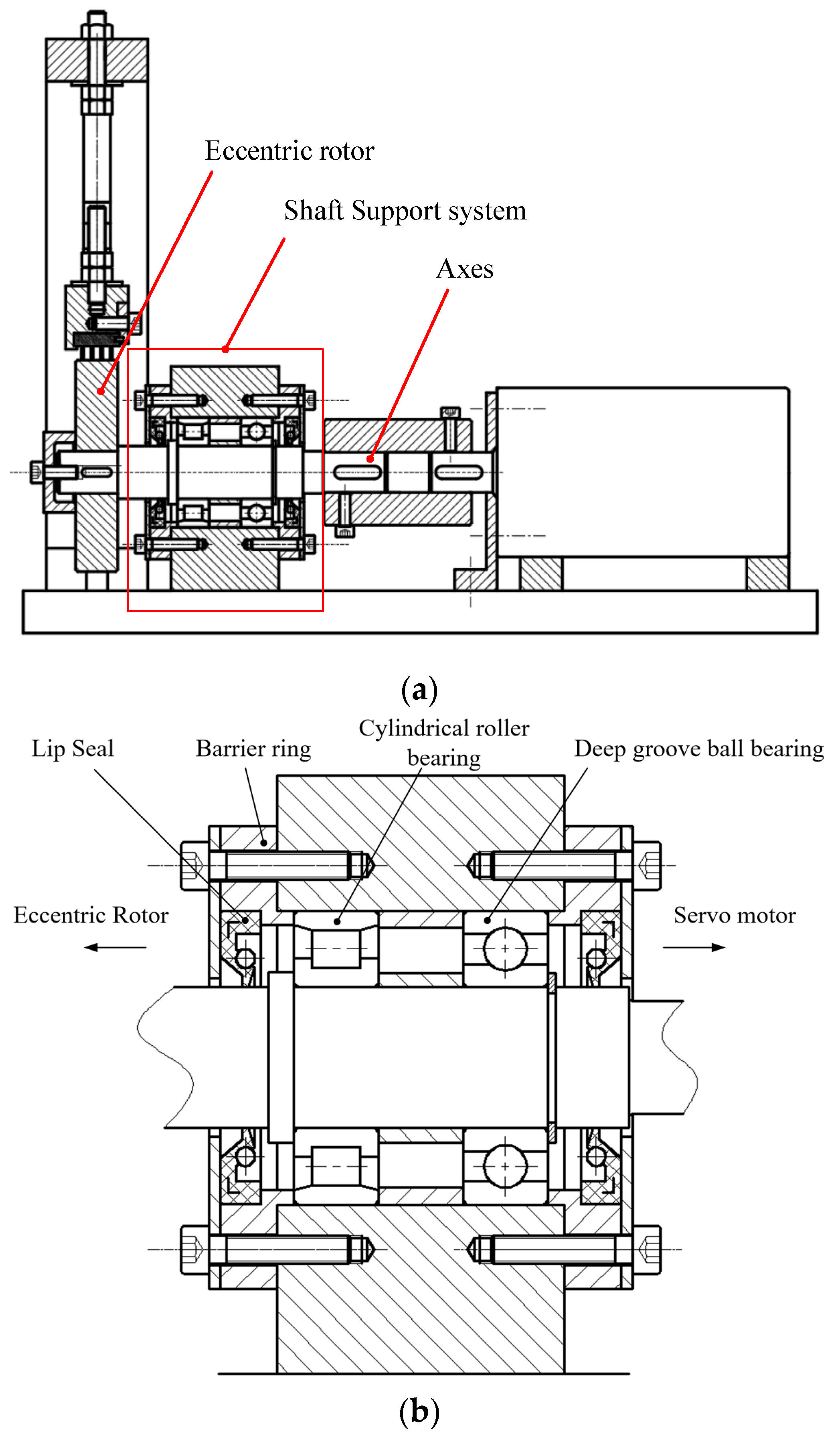
- Shaft Support System
- (4)
- Eccentric Rotor
- (5)
- Gantry Structure
- (6)
- Labyrinth Seal Specimen
- (7)
- Data Acquisition and Monitoring
2.2. Labyrinth Seal Leakage Experimental System
3. Numerical Model
3.1. Material Properties
3.2. Solid Finite Element Model
- (1)
- Boundary conditions replicated experimental constraints with three fixed surfaces on the seal specimen (Figure 6).
- (2)
- Material properties (Table 1) were imported from uniaxial compression tests. Plasticity models for PAI, PEEK, PTFE, and F500 were applied with the plastic constitutive behavior defined using tabular stress–plastic strain data derived from these experimental tests.
- (3)
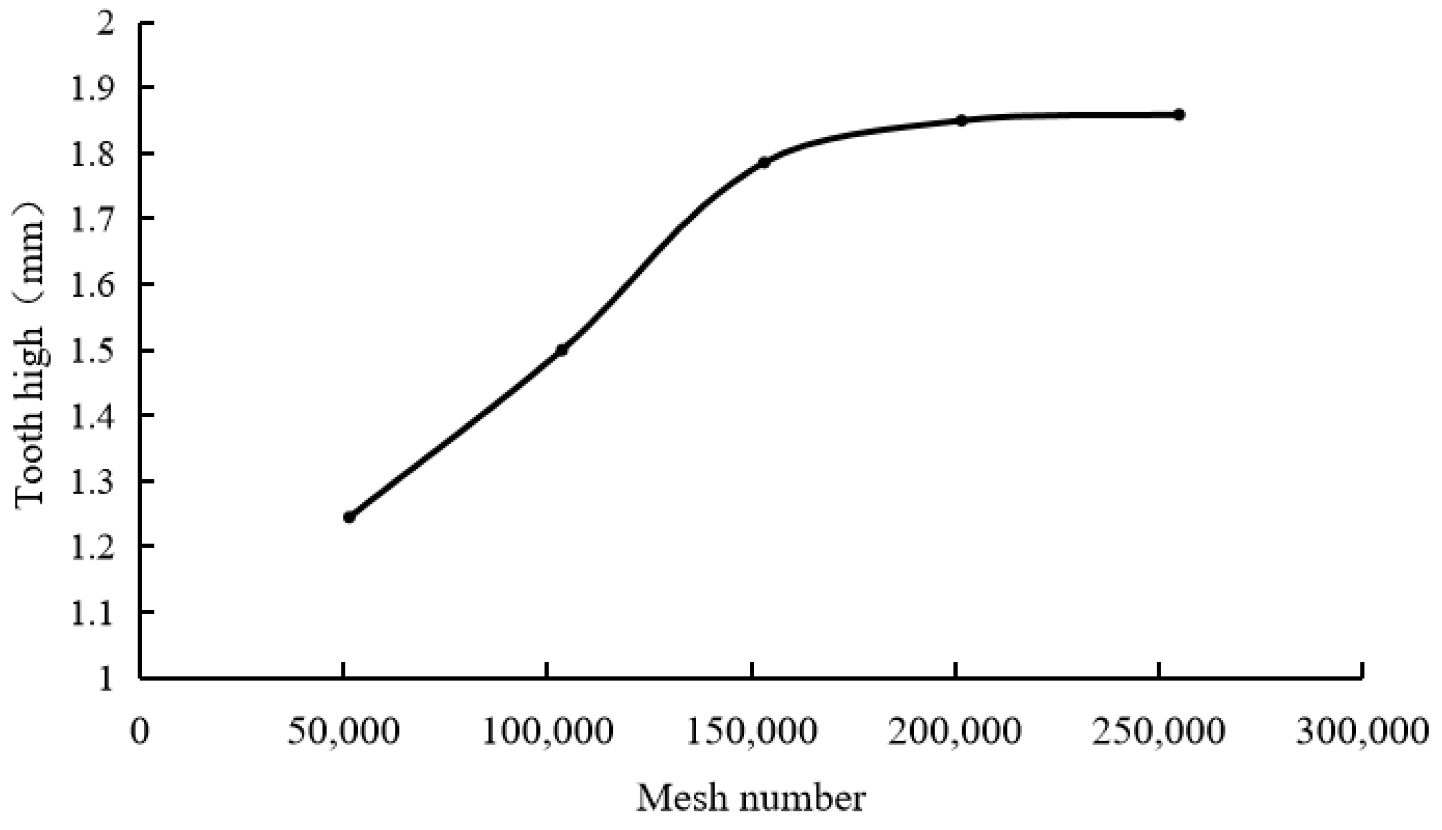
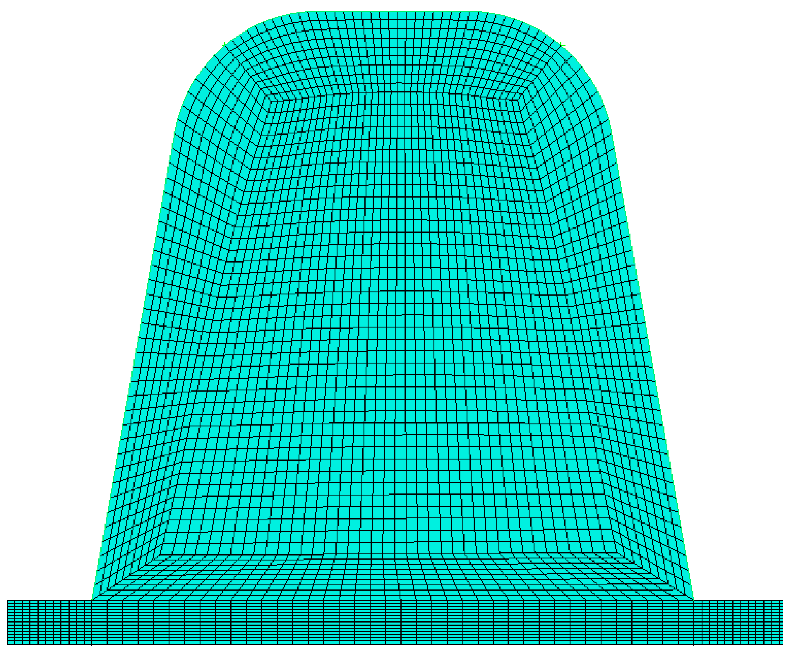
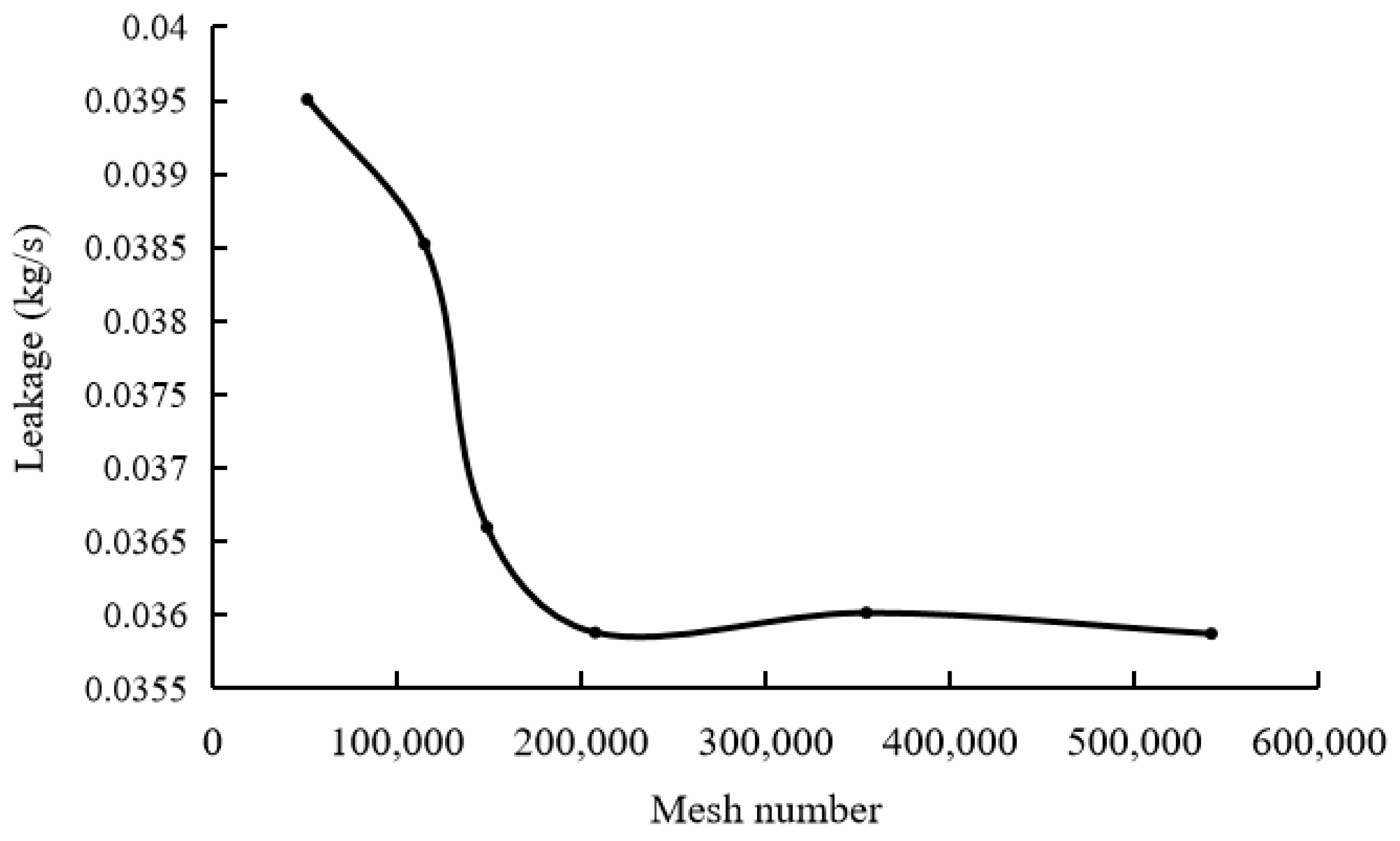
- Mesh sensitivity analysis: Mesh sensitivity analysis was conducted using PTFE material, selecting the post-impact tooth height as the convergence criterion. As shown in Figure 7, the results indicate that when the number of elements is approximately 254,000 (corresponding to an average element size of 0.05 mm), the post-impact tooth height converges to a stable value. Therefore, an average element size of 0.05 mm was adopted for all subsequent FEA calculations in this study, resulting in a model with approximately 254,000 tetrahedral elements.
3.3. CFD Model Development
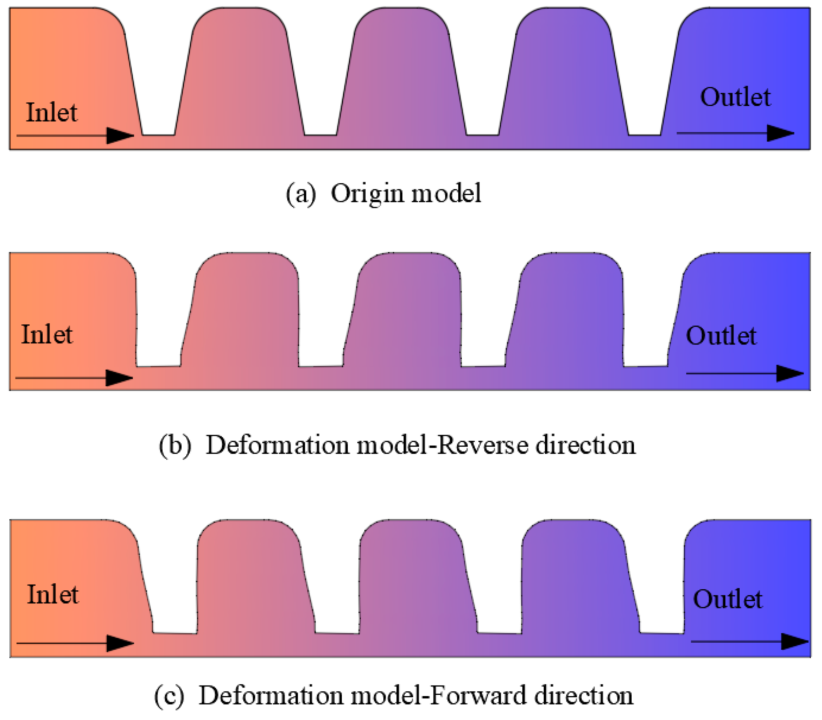
- (1)
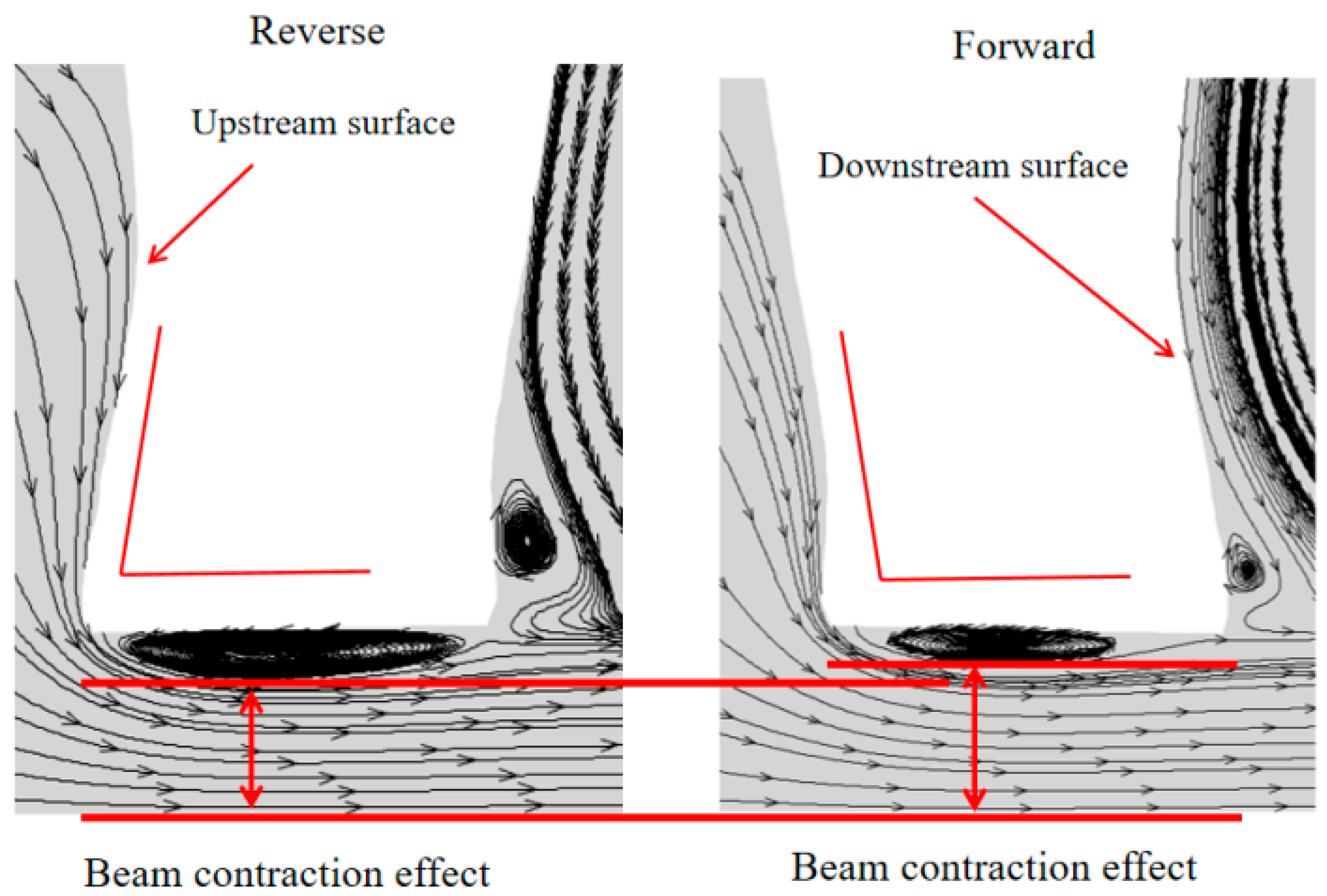
- Forward Flow: The direction of gas flow is aligned with the primary bending direction of the seal tooth profile.
- (2)
- Reverse Flow: The direction of gas flow is opposed to the primary bending direction of the seal tooth profile.
4. Results and Discussion
4.1. Comparative Analysis of Simulation and Experimental Results
4.2. Rub-Impact Experimental Results Analysis
- (1)
- Elastic Bending Phase: Initial rub-impact induced pronounced bending of the sealing teeth (Figure 13b); impact force as the dominant factor.
- (2)
- Progressive Wear Phase: Repeated collisions flattened the tooth tip, transitioning the dominant mechanism from impact to sliding friction.
- (3)
- Termination Phase: Wear reduced the tooth height until contact ceased (impact force < 0.5 N), marking the end of the rub-impact process (Figure 13c).
4.3. Solid Finite Element Analysis
- (1)
- Tooth Bending: dominant in low-interference conditions (0.1–0.2 mm), causing 5–10% height reduction.
- (2)
- Tip Mushrooming: observed at higher interference (0.3–0.4 mm) with tip width expanding by 25–40%.
- (3)
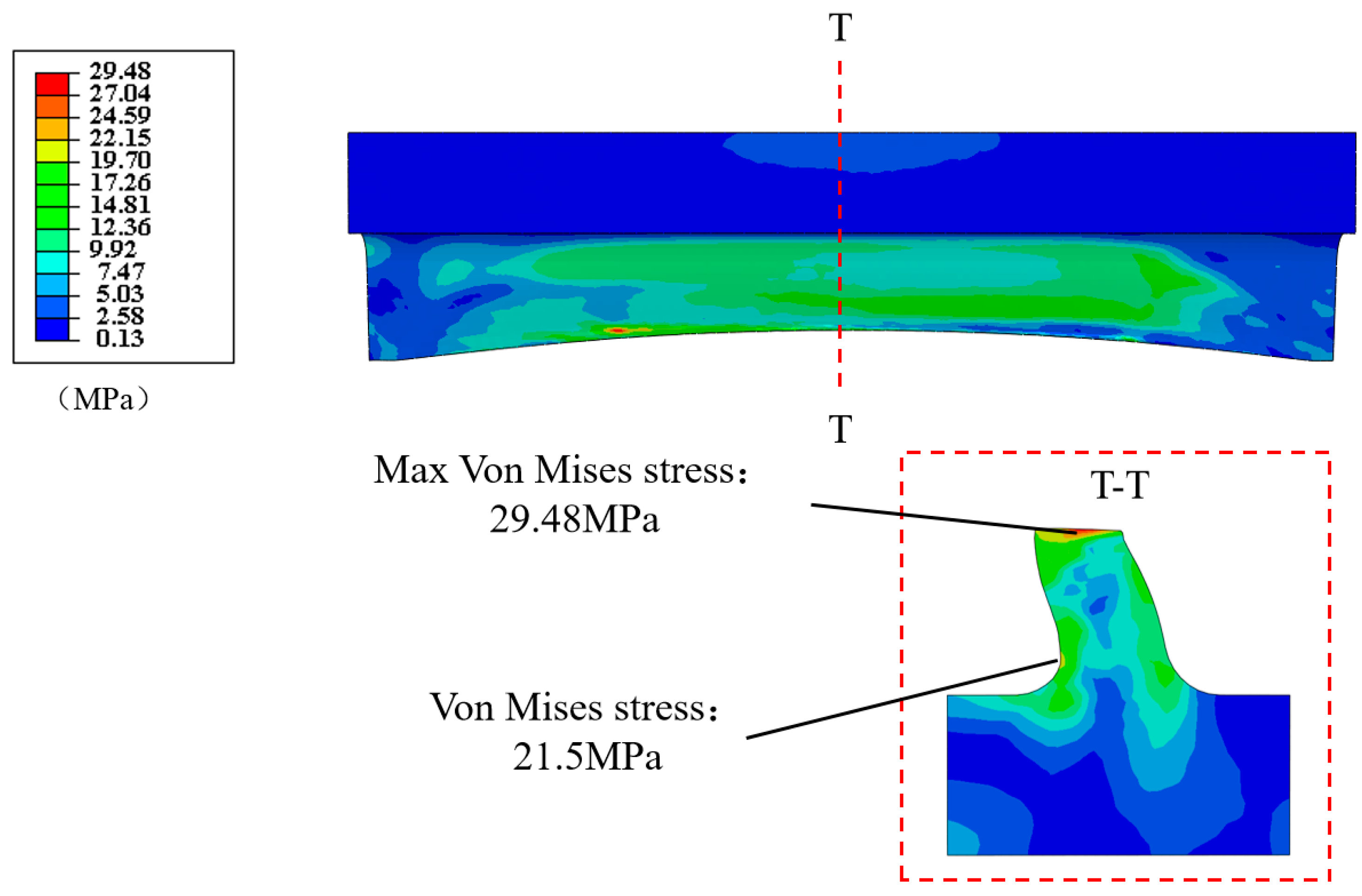
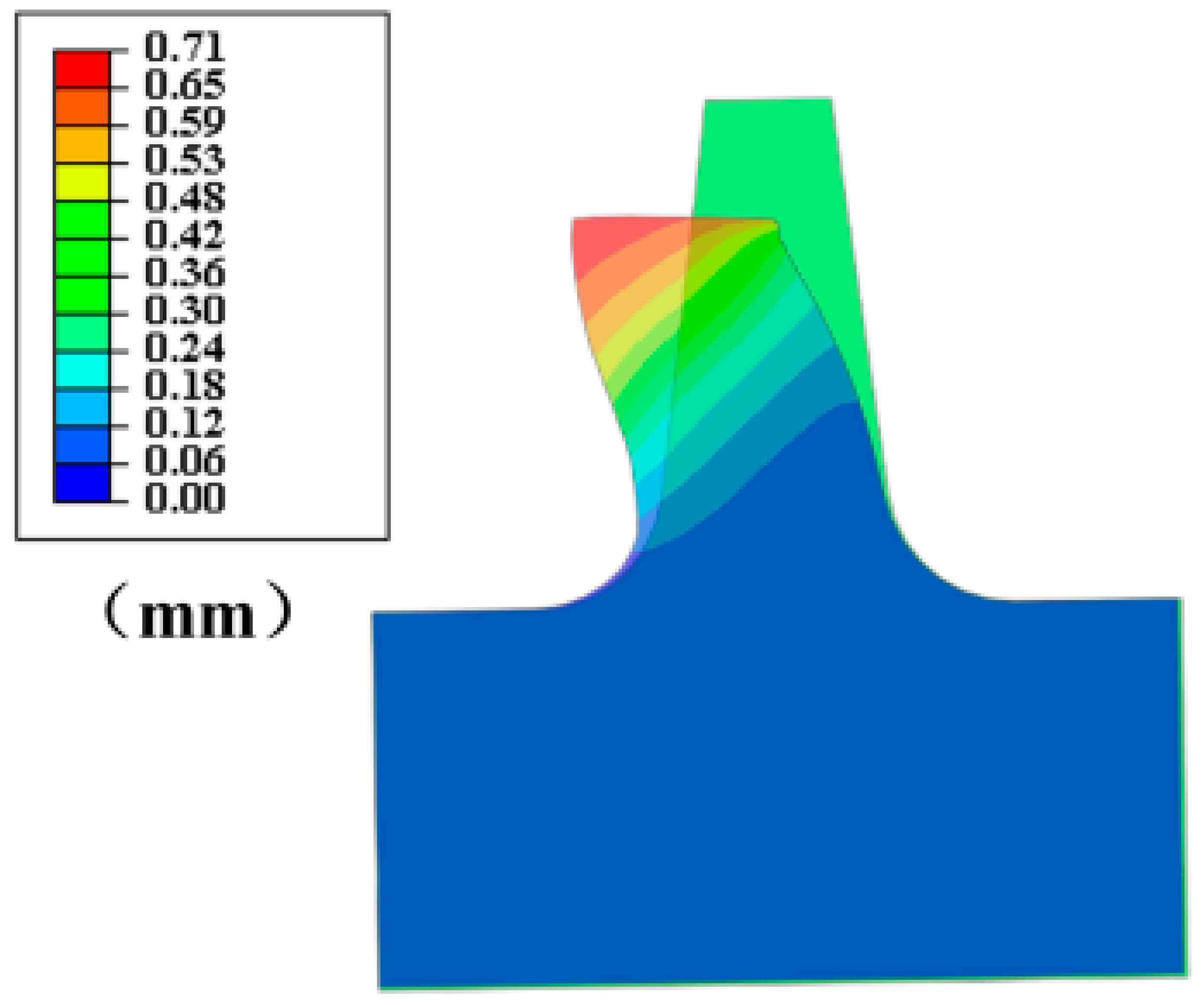
- Microscopic Tilting: A 2–5° tilt was observed at the tooth tip (Figure 15). In the FEA simulation, this tilting is attributed to the development of asymmetric contact forces and frictional resistance across the tooth tip surface during the rub-impact and sliding phase, which is a phenomenon consistent with real-world asymmetric contact conditions arising from factors like rotor eccentricity, seal movement, and manufacturing variations.
4.4. Leakage Rate Analysis
- (1)
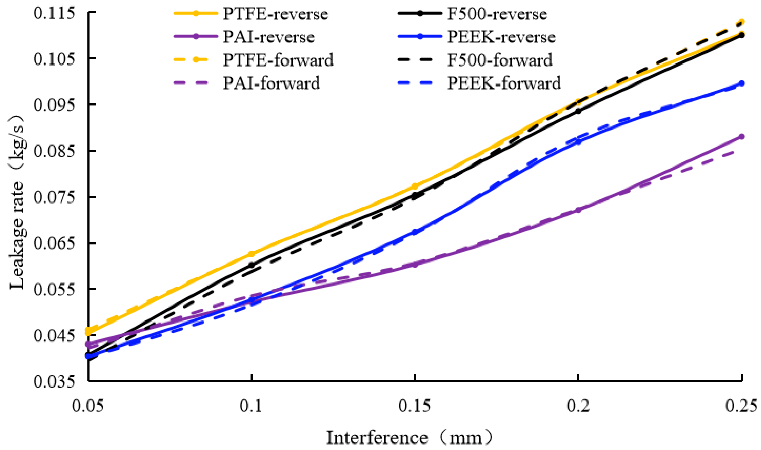
- PAI exhibited the lowest post-impact leakage (0.088 kg/s at 0.25 mm interference, reverse flow), which was approximately 20% less than PTFE (0.11 kg/s).
- (2)
- Reverse flow generally resulted in slightly lower leakage (0.5–3% reduction) compared to forward flow for the same material and interference, which was attributed to enhanced vena contracta effects (Figure 18).
5. Deformation Mechanisms of Sealing Teeth
5.1. Influence of Interference and Frequency on Deformation
- (1)
- Interference-Driven Deformation: Shaft eccentricity or vibration reduces the clearance between rotating and stationary components, inducing localized stress concentrations.
- (2)
- Frequency Independence: FEA results (Figure 19) revealed negligible differences in tooth deformation across frequencies (0.83–13.33 Hz) with <3% variation in tip height.
5.2. Material-Specific Deformation Patterns
- (1)
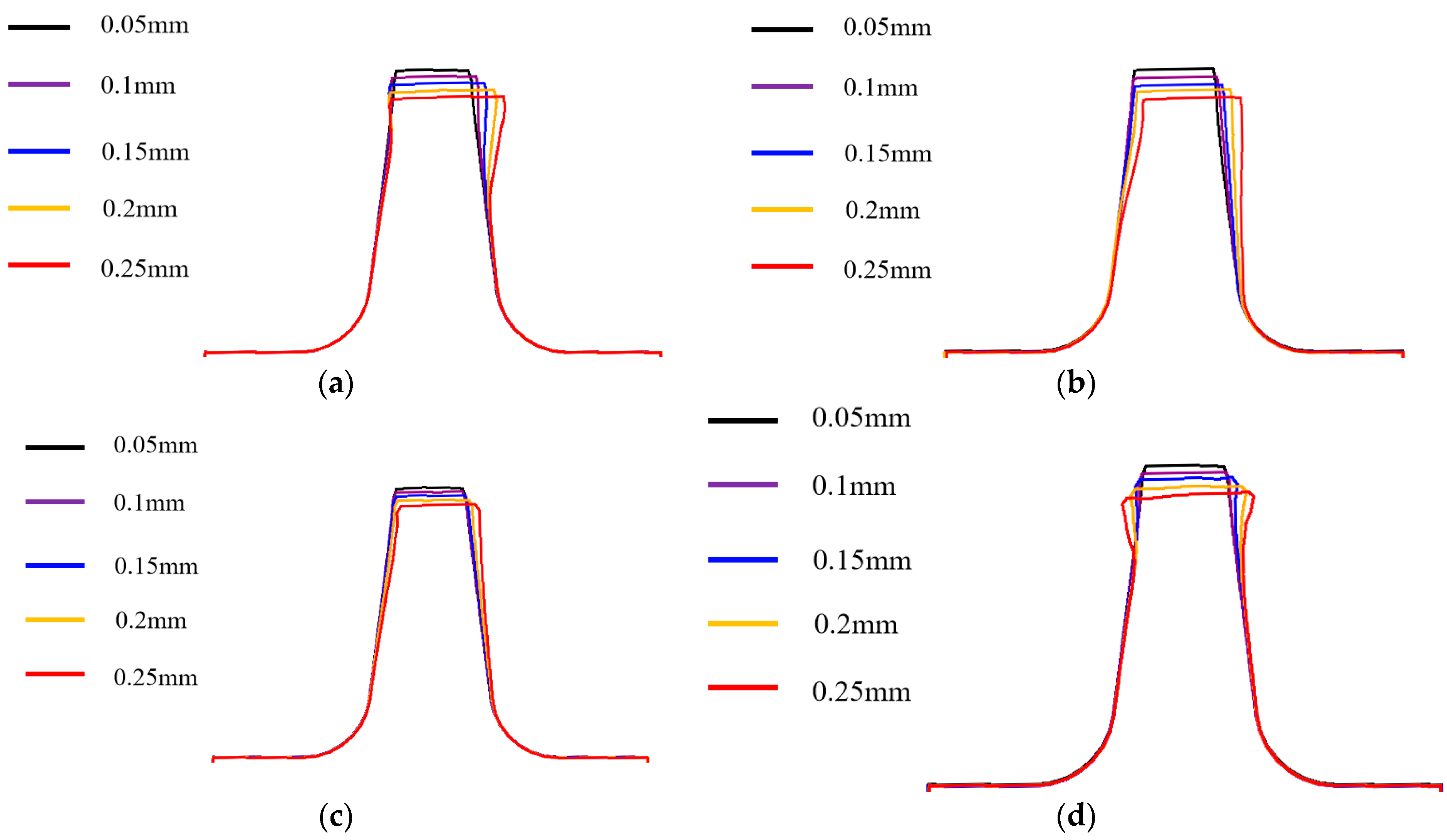
- Low-Strength Materials (PTFE, F500): exhibited progressive bending (height reduction: 1.3–12%) and severe tip mushrooming (width expansion: 2–60%) due to plastic yielding (Figure 20a,b).
- (2)
- High-Strength Thermoplastics (PAI, PEEK): demonstrated elastic-dominated deformation with limited bending (<9% height loss) and moderate tip widening (2–50%) even at 0.25 mm interference (Figure 20c,d).
- (1)
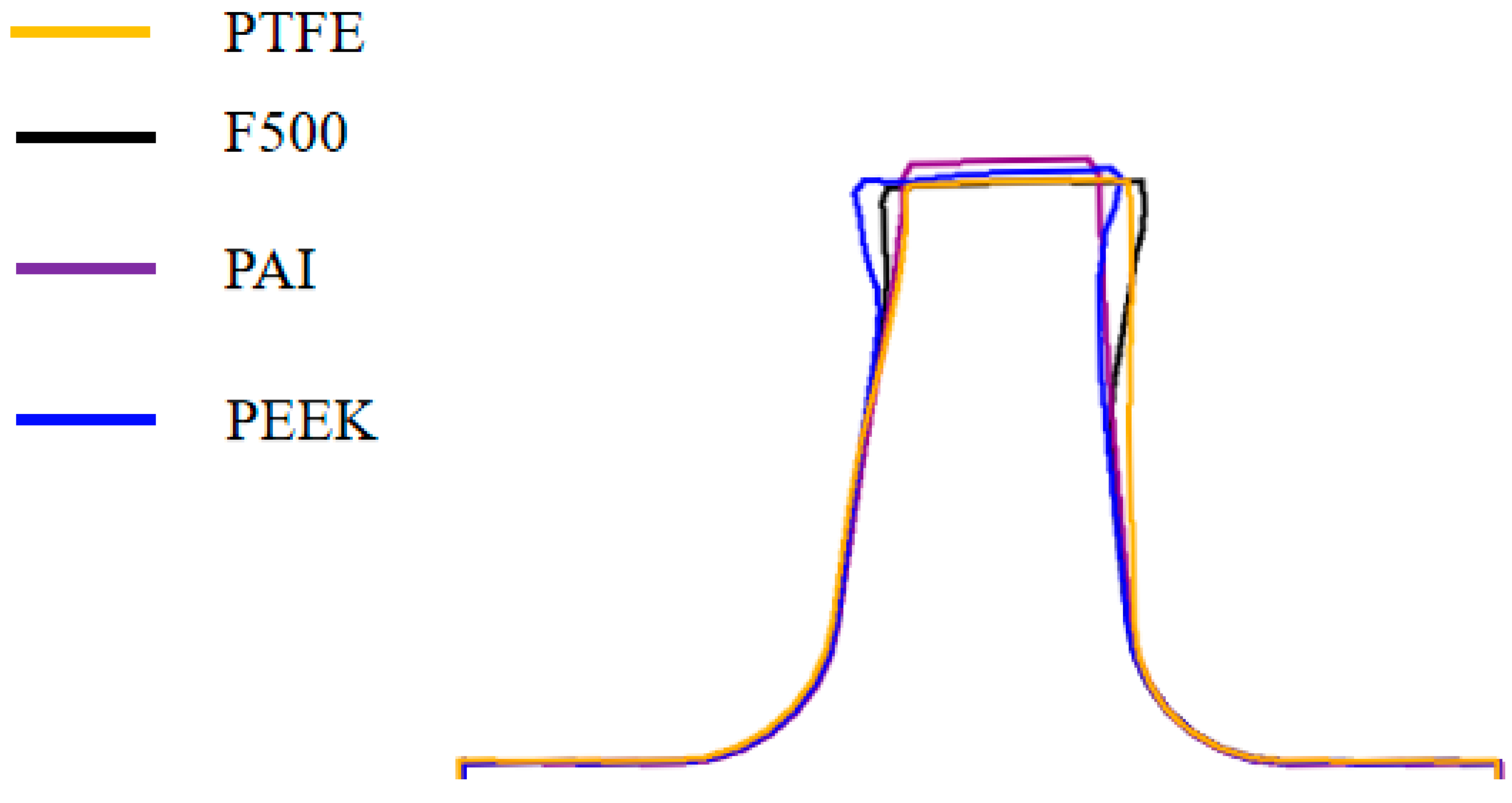
- PAI achieved the minimal clearance (0.29 mm vs. initial 0.15 mm), whereas PTFE and F500 suffered 150% greater clearance enlargement.
- (2)
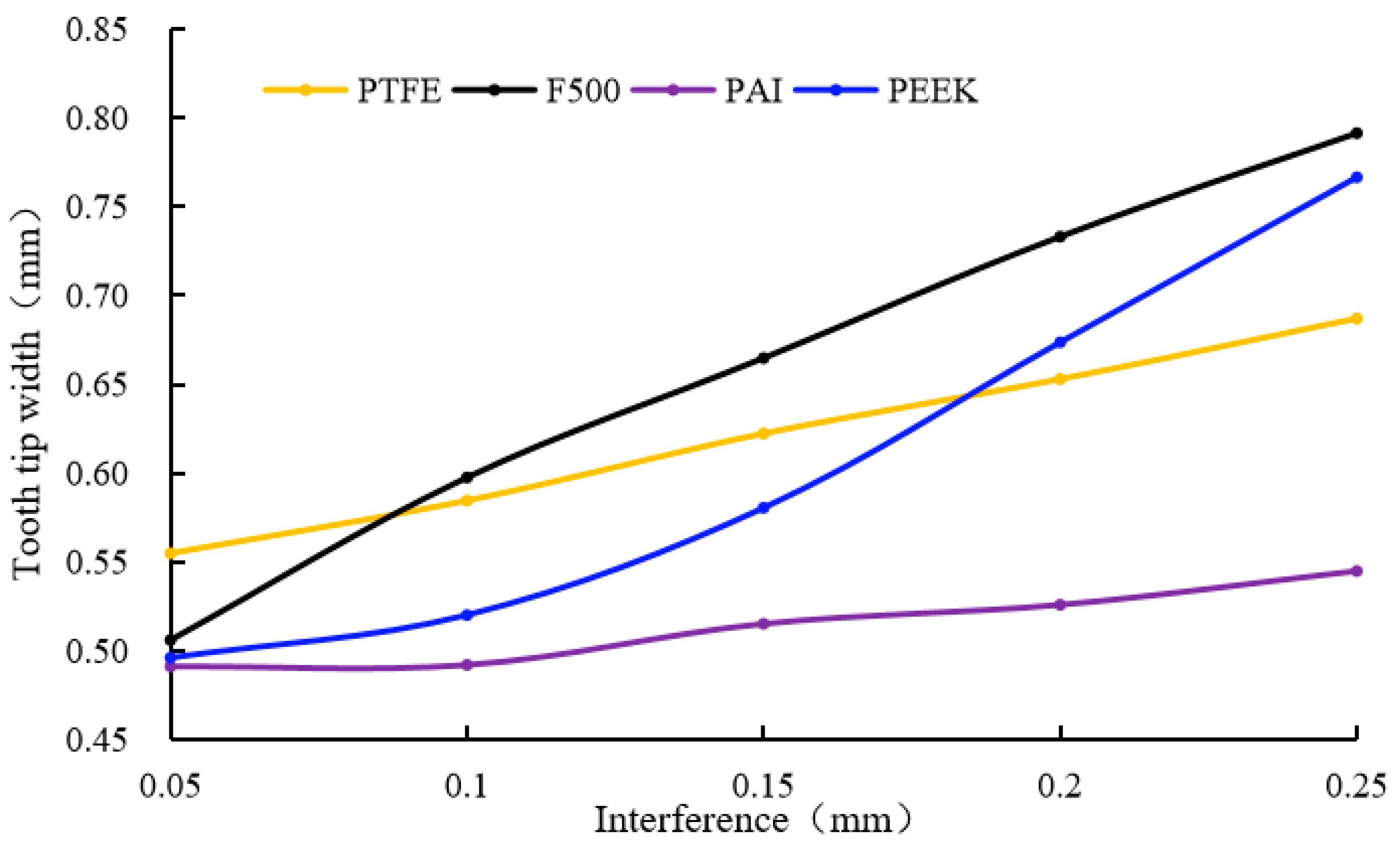
- Tip width expansion followed the order: F500 (+58.2%) > PEEK (+53.4%) > PTFE (+37.4%) > PAI (+9%).
5.3. Rebound Ratio and Leakage Correlation
6. Optimization Design and Performance Validation
6.1. Design Rationale and Structural Innovation
6.2. Finite Element Validation
6.3. Leakage Performance Evaluation
6.4. Analysis of Causes for Leakage Reduction
7. Conclusions
- (1)
- A key contribution is the successful development and utilization of a novel custom rub-impact test system. This experimental rig enabled the simulation of dynamic rotor–seal interactions and the precise quantification of contact forces under controlled interference levels (0.05–0.4 mm), providing valuable data on the rub-impact process and resulting tooth deformation.
- (2)
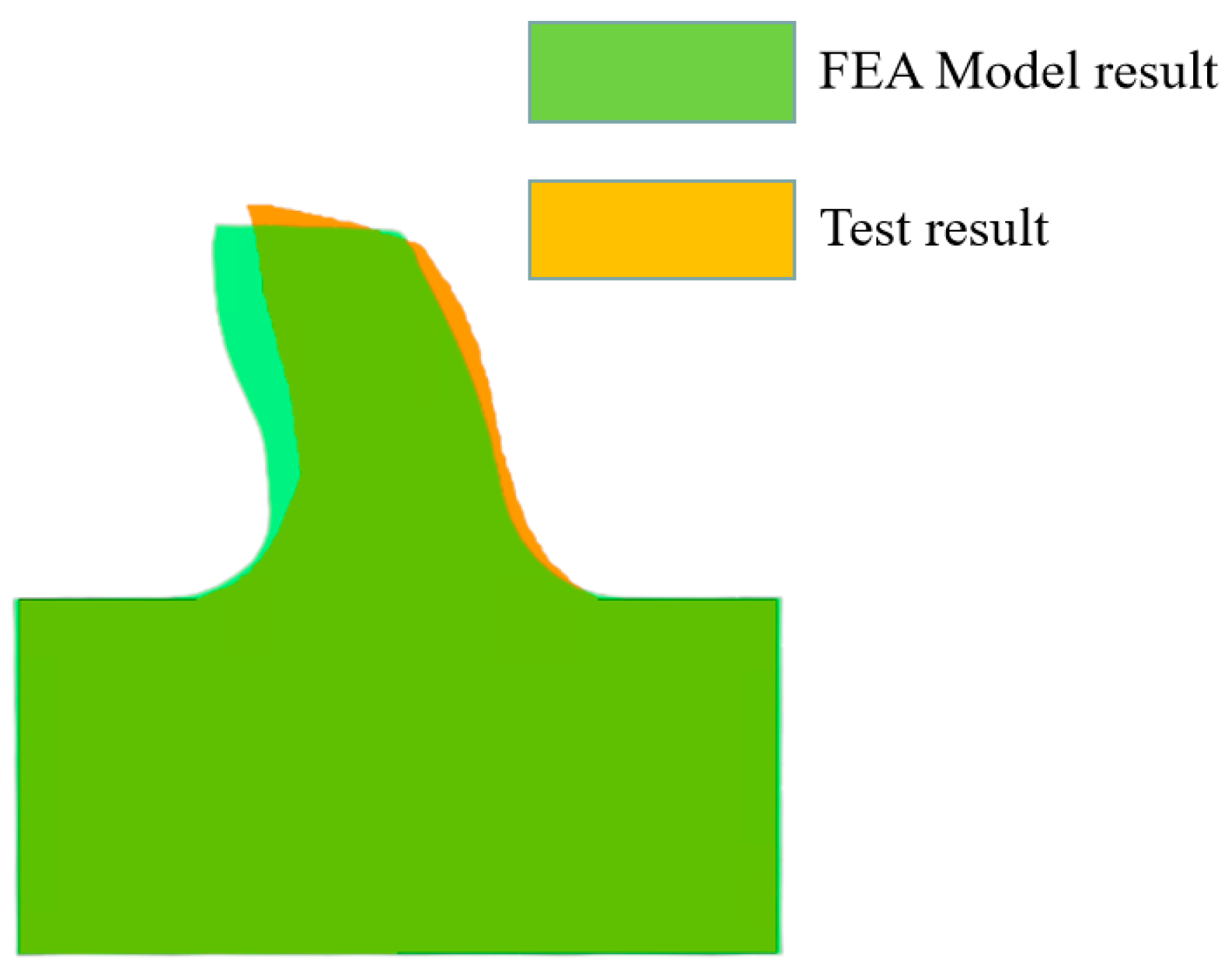
- Coupled finite element analysis (FEA) for structural deformation and computational fluid dynamics (CFD) for flow analysis were core to this investigation. The FEA model simulating rub-impact induced deformation was rigorously validated against experimental measurements, demonstrating high accuracy (e.g., a 5.1% discrepancy in post-impact tooth height for mild interference conditions) and confirming its ability to capture the dominant plastic yielding behavior observed in thermoplastic materials.
- (3)
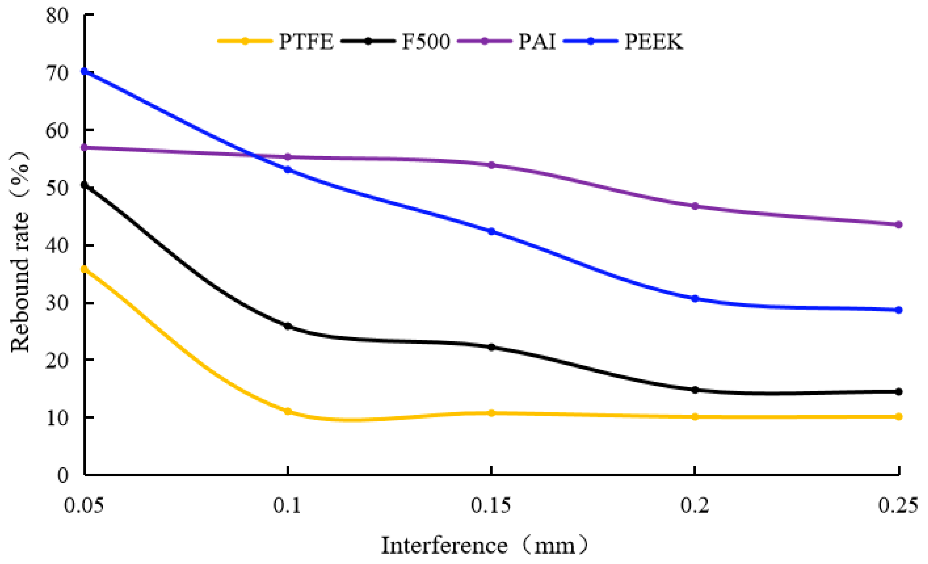
- The deformation mechanisms revealed that interference level is the primary operational parameter governing tooth deformation, causing significant reductions in tooth height (1.3–12%) and increases in tip width (2–60%) within the tested range (0.05–0.25 mm). In contrast, impact frequency variations (0.83–13.33 Hz) showed only a negligible impact on final tooth height (<3% change). A critical finding is the superior performance of high-strength thermoplastics like PAI and PEEK compared to conventional plastics (PTFE and F500). PAI and PEEK exhibited significantly higher elastic rebound ratios (up to 57% and 70.3%, respectively) and less permanent deformation, resulting in substantially smaller post-impact clearances (4.8–18.3% smaller) under identical conditions. This underscores their inherent resilience under rub-impact.
- (4)
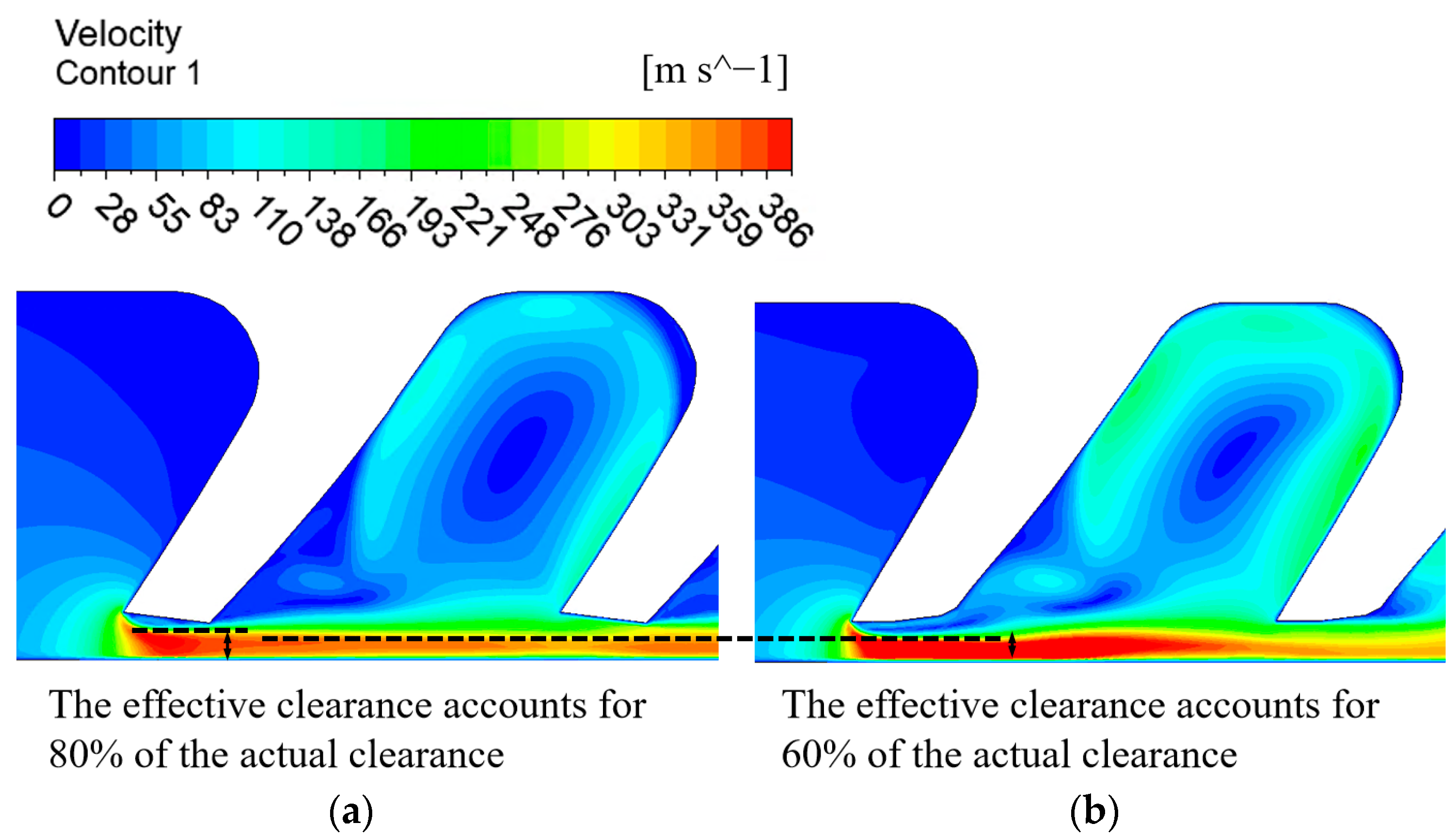
- Subsequent CFD simulations, utilizing the deformed geometries from FEA, elucidated the leakage dynamics. Leakage rates were predominantly correlated with interference, causing a substantial increase compared to the original state; at 0.25 mm interference (reverse flow), increases ranged from 151% (PAI) to 217% (PTFE), highlighting material-dependent performance degradation. Meanwhile, tooth orientation modulated leakage by 0.5–3% through the vena contracta effect. Furthermore, the relative orientation of the deformed tooth profile to the gas inflow direction was found to modulate leakage (by 20–40%) primarily through its influence on the vena contracta effect. The ‘reverse flow’ configuration, where gas flow opposed the tooth bending, enhanced streamline contraction and reduced effective clearance.
- (5)
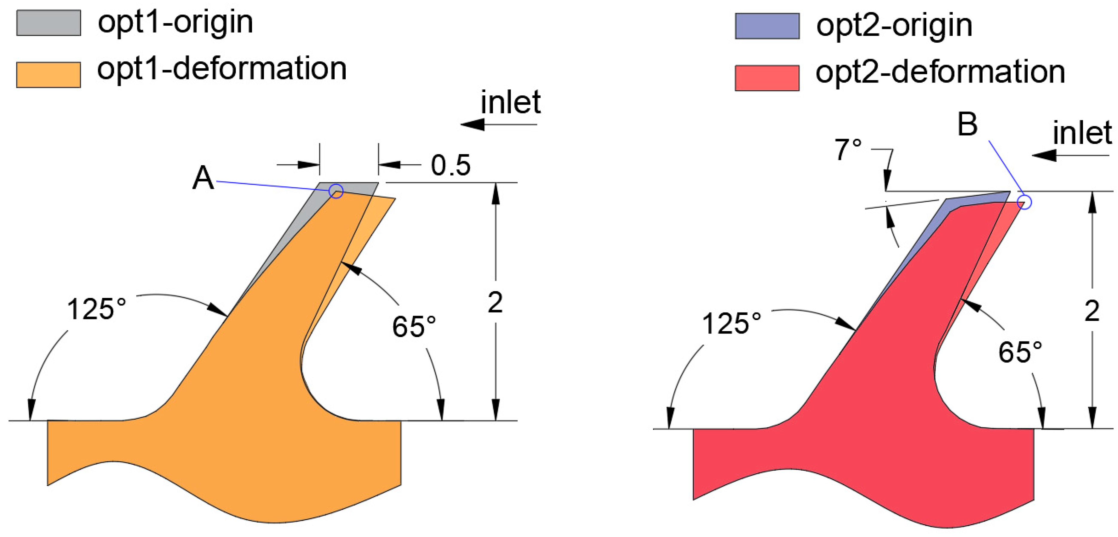
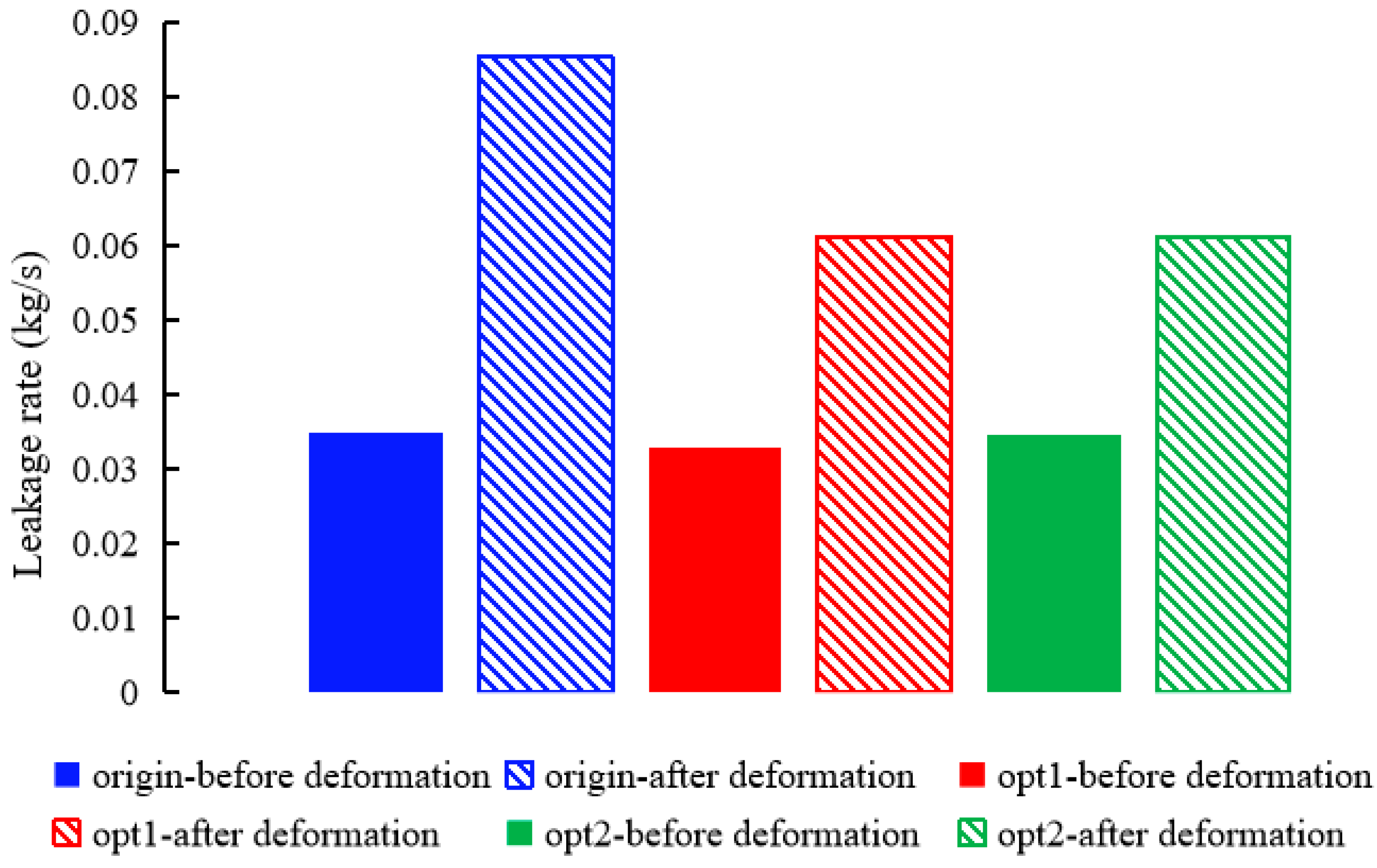
- Leveraging these comprehensive insights into deformation and leakage mechanisms, two optimized inclined-tooth geometries (Opt1 and Opt2) based on the superior PAI material were designed. CFD analysis predicted significant leakage reductions for these designs after rub-impact with Opt1 achieving a 28.2% reduction and Opt2 achieving a 28.1% reduction compared to the original geometry. While Opt2 exhibited a slightly lower rebound ratio than Opt1 due to differences in localized contact mechanics influenced by its angled tip, its final post-impact geometry proved equally effective in minimizing leakage, validating the potential of tailored geometric optimization based on the understanding of deformation effects.
Author Contributions
Funding
Data Availability Statement
Conflicts of Interest
References
- Lin, Z.; Wang, X.; Yuan, X.; Shibukawa, N.; Noguchi, T. Investigation and improvement of the staggered labyrinth seal. Chin. J. Mech. Eng. 2015, 28, 402–408. [Google Scholar] [CrossRef]
- Rhode, D.L.; Adams, R.G. Rub-groove width and depth effects on flow predictions for straight-through labyrinth seals. J. Tribol. 2004, 126, 781–787. [Google Scholar] [CrossRef]
- Whalen, J.K.; Dugas, J.R., Jr. Upgrading Centrifugal Compressors with Polymer Seals in an Ethylene Plant—A Case History. In Proceedings of the Twenty-Ninth Turbo-machinery Symposium, Turbomachinery Laboratory, George R. Brown Convention Center, Houston, TX, USA, 18–21 September 2000; Texas A&M University: College Station, TX, USA, 2000; pp. 31–37. [Google Scholar]
- Kirk, G.; Gao, R. Influence of preswirl on rotor dynamic characteristics of labyrinth seals. Tribol. Trans. 2012, 55, 357–364. [Google Scholar] [CrossRef]
- Vannini, G.; Bertoneri, M.; Nielsen, K.K.; Iudiciani, P.; Stronach, R. Experimental results and computational fluid dynamics simulations of labyrinth and pocket damper seals for wet gas compression. J. Eng. Gas Turbines Power 2016, 138, 052501. [Google Scholar] [CrossRef]
- Corral, R.; Greco, M.; Vega, A. Effective clearance and differential gapping impact on seal flutter modeling and validation. J. Turbomach. 2022, 144, 071010. [Google Scholar] [CrossRef]
- Gu, Q.L.; Zhang, W.F.; Chen, L.Q.; Ma, K.; Li, C.; Yang, J.A. Study on the Critical Stable State of the Labyrinth Seal. J. Mech. Eng. 2020, 56, 144–151. [Google Scholar]
- Cao, H.C.; Xu, Y.R.; Sun, N.N.; Lu, J.; Zhu, G.X.; Li, Y.J. Analysis and Experimental Research for Leaking Behavior of Labyrinth Seals under Gas-liquid Two-phase Conditions. China Mech. Eng. 2023, 34, 623–629. [Google Scholar]
- Yang, Y.; Mi, Z.; Zhang, W.; Chang, J.; Liu, Y.; Zhong, B.; Yang, W. Experimental Study on the Effect of Rubbing Mode on Radial Crack Initiation in Labyrinth Seal Fins of Shrouded Turbine Blade. Aerospace 2022, 9, 441. [Google Scholar] [CrossRef]
- Pychynski, T.; Hofler, C.; Bauer, H.J. Experimental study on the friction contact between a labyrinth seal fin and a honeycomb stator. J. Eng. Gas Turbines Power 2016, 138, 062501. [Google Scholar] [CrossRef]
- Subramanian, S.; Sekhar, A.S.; Prasad, B. Influence of combined radial location and growth on the leakage performance of a rotating labyrinth gas turbine seal. J. Mech. Sci. Technol. 2015, 29, 2535–2545. [Google Scholar] [CrossRef]
- Katcher, K.M.; Revak, T.; Rimpel, A.; Ratay, J.; Brun, K. Abradable Seal Test Rig for Quantifying Abradable Material Performance During Labyrinth Seal Rubs in Centrifugal Compressors: Design and Test Results. In Proceedings of the ASME Turbo Expo 2022: Turbomachinery Technical Conference and Exposition, Rotterdam, The Netherlands, 13–17 June 2022; p. V007T19A005. [Google Scholar]
- Yang, S.; Tan, B.; Deng, X. Numerical and Experimental Investigation of the Sealing Effect of a Specific Labyrinth Seal Structure. Math. Probl. Eng. 2019, 2019, 9851314. [Google Scholar] [CrossRef]
- Whalen, J.K.; Alvarez, E.; Palliser, L.P. Thermoplastic labyrinth seals for centrifugal compressors. In Proceedings of the Thirty-Third Turbomachinery Symposium, Houston, TX, USA, 20–23 September 2004. [Google Scholar]
- Rhode, D.L.; Adams, R.G. Computed Effect of Rub-Groove Size on Stepped Labyrinth Seal Performance. In Proceedings of the ASME Turbo Expo 2000: Power for Land, Sea, and Air. Volume 3: Heat Transfer; Electric Power; Industrial and Cogeneration, Munich, Germany, 8–11 May 2000; p. V003T01A093. [Google Scholar]
- Dogu, Y.; Sertcakan, M.C.; Bahar, A.S.; Pişkin, A.; Arıcan, E.; Kocagül, M. Computational fluid dynamics investigation of labyrinth seal leakage performance depending on mushroom-shaped tooth wear. J. Eng. Gas Turbines Power 2016, 138, 032503. [Google Scholar] [CrossRef]
- Dogu, Y.; Sertcakan, M.C.; Gezer, K.; Kocagül, M.; Arıcan, E.; Ozmusul, M.S. Labyrinth Seal Leakage Degradation Due to Various Types of Wear. J. Eng. Gas Turbines Power 2017, 139, 062504. [Google Scholar] [CrossRef]
- Yan, X.; Wang, H.; He, K. Investigations into rubbing wear behavior of honeycomb land against labyrinth fin with periodic-cell model. Proceedings of the Institution of Mechanical Engineers. Part A J. Power Energy 2024, 238, 1399–1413. [Google Scholar] [CrossRef]
- Jiang, J.; Yang, Y.; Huang, W.; Li, Y. Numerical and experimental investigation on uniformity of pressure loads in labyrinth seal. Adv. Mech. Eng. 2017, 9, 1687814017728455. [Google Scholar] [CrossRef]
- Dai, X.; Yan, X.; He, K.; Li, J.; Feng, Z. Numerical investigations of leakage performance degradations in labyrinth and flexible seals due to wear. J. Eng. Gas Turbines Power 2021, 143, 051003. [Google Scholar] [CrossRef]
- Xu, J. Effects of Operating Damage of Labyrinth Seal on Seal Leakage and Wheel Space Hot Gas Ingress; Texas A&M University: College Station, TX, USA, 2007. [Google Scholar]
- Dowson, P.; Walker, M.S.; Watson, A.P. Development of abradable and rub-tolerant seal materials for application in centrifugal compressors and steam turbines. Seal. Technol. 2004, 2004, 5–10. [Google Scholar] [CrossRef]
- Zhang, M.; Childs, D.W. Effects of increased tooth clearance on the performance of a labyrinth seal with oil-rich bubbly laminar flow. J. Eng. Gas Turbines Power 2021, 143, 111007. [Google Scholar] [CrossRef]
- Xiang, Z.; Ying, H.J.; Xiu, Q.Q.; Zhi, Q.Z.; Guang, H.H.; Kai, H. Inlet preswirl dependence research on three different labyrinth seals. Tribol. Int. 2024, 176, 107929. [Google Scholar]
- Huang, J.Q.; Cao, X.Q.; Chen, W.B.; Guo, X.J.; Li, M.; Wang, W.J.; Dong, S.J.; Liu, L.; Chen, M.Z. A comprehensive review of thermally sprayed abradable sealing coatings: Focusing on abradability. Chin. J. Aeronaut. 2024, 37, 1–25. [Google Scholar] [CrossRef]
- Zhang, X.; Jiao, Y.H.; Du, H.Z.; Huo, G.H.; Xu, Y.Y.; Che, R. Transient investigations of teeth on rotor and teeth on stator modified labyrinth seals. Tribol. Int. 2024, 192, 109296. [Google Scholar] [CrossRef]
- Zhang, B.; Marshall, M.; Lewis, R. Investigating Al-Si base abradable material removal mechanism with axial movement in labyrinth seal system. Wear 2022, 510, 204496. [Google Scholar] [CrossRef]
- Yan, X.; Dai, X.; He, K. Experimental Study on Rubbing Wear Characteristics of Labyrinth Seal With Trapezoidal Fins. J. Tribol. 2022, 144, 032301. [Google Scholar] [CrossRef]
- Sun, W.W.; Liu, Y.; Li, Y.J.; Jiang, J. Analysis and experimental verification on the leakage of labyrinth seals under multiple factors. J. Tsinghua Univ. (Sci. Technol.) 2024, 64, 1414–1423. [Google Scholar]
- Liu, Y.; Huang, M.; Li, Y.J.; An, Q.; Jiang, J. Research on Leakage Characteristics of Thermoplastic Labyrinth Seals on High Pressure Differential. J. Mech. Eng. 2024, 60, 194–204. [Google Scholar]







| Properties Materials | PTFE | F500 | PAI | PEEK |
|---|---|---|---|---|
| Density (kg/m3) | 2200 | 2320 | 1410 | 1310 |
| Elastic modulus (MPa) | 1400 | 1200 | 2651 | 3700 |
| Poisson’s ratio | 0.46 | 0.36 | 0.36 | 0.36 |
| Compressive yield strength (MPa) | 15 | 12 | 34.47 | 75 |
| Parameters | Settings |
|---|---|
| Solution method | Steady |
| Turbulence model | k-ε turbulence model |
| Boundary condition | Pressure inlet; pressure outlet |
| Solution methods | SIMPLEC |
| Residuals | 1 × 10⁻⁶ |
Disclaimer/Publisher’s Note: The statements, opinions and data contained in all publications are solely those of the individual author(s) and contributor(s) and not of MDPI and/or the editor(s). MDPI and/or the editor(s) disclaim responsibility for any injury to people or property resulting from any ideas, methods, instructions or products referred to in the content. |
© 2025 by the authors. Licensee MDPI, Basel, Switzerland. This article is an open access article distributed under the terms and conditions of the Creative Commons Attribution (CC BY) license (https://creativecommons.org/licenses/by/4.0/).
Share and Cite
Ma, F.; Yang, Z.; Liu, Y.; Suo, S.; Su, P. Thermoplastic Labyrinth Seals Under Rub Impact: Deformation Leakage Mechanisms and High Efficiency Optimization. Lubricants 2025, 13, 250. https://doi.org/10.3390/lubricants13060250
Ma F, Yang Z, Liu Y, Suo S, Su P. Thermoplastic Labyrinth Seals Under Rub Impact: Deformation Leakage Mechanisms and High Efficiency Optimization. Lubricants. 2025; 13(6):250. https://doi.org/10.3390/lubricants13060250
Chicago/Turabian StyleMa, Fei, Zhengze Yang, Yue Liu, Shuangfu Suo, and Peng Su. 2025. "Thermoplastic Labyrinth Seals Under Rub Impact: Deformation Leakage Mechanisms and High Efficiency Optimization" Lubricants 13, no. 6: 250. https://doi.org/10.3390/lubricants13060250
APA StyleMa, F., Yang, Z., Liu, Y., Suo, S., & Su, P. (2025). Thermoplastic Labyrinth Seals Under Rub Impact: Deformation Leakage Mechanisms and High Efficiency Optimization. Lubricants, 13(6), 250. https://doi.org/10.3390/lubricants13060250


