Article

Thermoplastic Labyrinth Seals Under Rub Impact: Deformation Leakage Mechanisms and High Efficiency Optimization

1
Mechanical Electrical Engineering School, Beijing Information Science & Technology University, Beijing 100192, China
2
State Key Laboratory of Tribology, Department of Mechanical Engineering, Tsinghua University, Beijing 100084, China
*
Author to whom correspondence should be addressed.
Lubricants 2025, 13(6), 250; https://doi.org/10.3390/lubricants13060250
Submission received: 10 April 2025 / Revised: 28 May 2025 / Accepted: 3 June 2025 / Published: 4 June 2025
(This article belongs to the Special Issue Recent Advances in Sealing Technologies)

Abstract

:
Labyrinth seals, extensively used in aerospace and turbomachinery as non-contact sealing devices, undergo accelerated wear and enhanced leakage due to repeated rub-impact between rotating shafts and sealing rings. To address the problem of increased leakage under rub-impact conditions, this research integrates experimental and numerical methods to investigate the deformation mechanisms and leakage characteristics of thermoplastic labyrinth seals. A custom designed rub-impact test rig was constructed to measure dynamic forces and validate finite element analysis (FEA) models with an error of 5.1% in predicting tooth height under mild interference (0.25 mm). Computational fluid dynamics (CFD) simulations further demonstrated that thermoplastic materials, such as PAI and PEEK, displayed superior resilience (with rebound ratios of 57% and 70.3%, respectively). Their post-impact clearances were 4.8–18.3% smaller than those of PTFE and F500. Leakage rates were predominantly correlated with interference, causing a substantial increase compared to the original state; at 0.25 mm interference (reverse flow), increases ranged from 151% (PAI) to 217% (PTFE), highlighting material-dependent performance degradation. Meanwhile, tooth orientation modulated leakage by 0.5–3% through the vena contracta effect. Based on these insights, two optimized inclined-tooth geometries were designed, reducing leakage by 28.2% (Opt1) and 28.1% (Opt2) under rub-impact. These findings contribute to the development of high-performance labyrinth seals suitable for extreme operational environments.

1. Introduction

In aerospace and turbomachinery systems, ensuring high sealing efficiency is paramount for guaranteeing operational safety, optimizing energy performance, and reducing environmental impact. The integrity of seals directly influences critical parameters such as compressor and turbine efficiency, shaft dynamics, and overall system reliability. However, efficiency degradation stemming from unwanted leakage across seal clearances or even catastrophic seal failure remains a significant challenge in engineering practice [1]. Among various non-contact sealing technologies, labyrinth seals are widely adopted in these demanding applications due to their inherent durability, relatively simple design, and adaptability to high temperatures and pressures [2].
Despite their robustness, labyrinth seals are susceptible to performance degradation caused by repeated contact between the high-speed rotating shaft and the stationary sealing rings. This phenomenon, known as rub-impact, accelerates wear in conventional metallic labyrinth seals, leading to irreversible damage on both the seal teeth and the rotor surface [3,4]. Such damage directly increases the seal clearance, resulting in unpredictable leakage surges and significant performance loss. Field observations and dedicated studies have confirmed that severe rub-impact events can drastically reduce the operational lifespan of seals, sometimes by over 40% in high-speed rotor systems [5], highlighting the critical urgency of thoroughly investigating the leakage mechanisms that arise under such dynamic conditions.
Conventional metallic labyrinth seals exhibit inherent limitations when subjected to severe rub-impact. The high stiffness and low damping capacity of metallic materials amplify collision forces during contact, potentially leading to increased vibration, rotor instability, and heightened systemic risks [6,7,8,9]. While metallic seals have been extensively studied [10,11], the potential for significant wear and irreversible damage persists.
In contrast, advanced thermoplastic materials, such as polyamide-imide (PAI) and polyetheretherketone (PEEK), have emerged as promising alternatives for labyrinth seal applications, particularly in scenarios involving potential rub-impact. These polymers offer a superior combination of properties, including relatively high strength at moderate temperatures, excellent tribological performance, and, critically, a lower elastic modulus compared to metals. This lower stiffness facilitates elastic bending upon contact, enabling the seal tooth to deflect and recover post-impact, thereby minimizing abrasive wear on the shaft and preserving sealing integrity to a greater extent than metallic materials [12,13]. Although their thermal tolerance imposes limitations in extreme high-temperature environments, thermoplastics demonstrate exceptional performance in moderate-temperature applications relevant to many compressor and turbine stages [14].
Historically, research on labyrinth seal performance under rub-impact has primarily concentrated on metallic seals, often employing idealized models of wear or deformation. For instance, studies have simulated wear patterns assuming simplified tooth geometries [15] or analyzed leakage based on pre-defined wear depths without considering material-specific elastic–plastic behavior [16]. Numerical methods, particularly computational fluid dynamics (CFD) for flow analysis and finite element analysis (FEA) for structural mechanics, have been extensively applied to analyze seal performance [17,18,19]. However, many FEA studies on seal deformation have focused on metallic materials or idealized rigid-body contact, often excluding the complex elastic–plastic deformation dynamics characteristic of thermoplastics under dynamic impact loads [20]. Similarly, while CFD has correlated idealized tooth bending with leakage [21], these models typically do not incorporate the realistic deformed geometries resulting from material-specific rub-impact and subsequent recovery. Studies have also investigated the wear behavior of thermoplastic materials suitable for seals [22,23], but a systematic link between specific material deformation characteristics under dynamic rub-impact and subsequent sealing performance degradation has often been missing. Although some pioneering work has demonstrated the practical benefits and extended lifespan of thermoplastic labyrinth seals in real centrifugal compressors [24], a fundamental analysis correlating the thermoplastic material’s deformation mechanisms under dynamic rub-impact with the resulting leakage characteristics, and leveraging this understanding for targeted geometric optimization, remains an area requiring further in-depth investigation. Furthermore, while optimization strategies for labyrinth seals have explored various geometric parameters [25,26,27,28], these often do not account for the significant post-impact structural changes that occur particularly with deformable materials.
Consequently, there is a clear and pressing need for research that integrates the experimental observation of dynamic rub-impact with advanced coupled structural and fluid dynamics modeling to comprehensively understand the transient and post-impact behavior of thermoplastic labyrinth seals, specifically focusing on how material properties and tooth geometry influence deformation and subsequent leakage. This knowledge is crucial for designing robust and high-efficiency seals capable of withstanding operational disturbances.
To address this critical research gap and advance the state-of-the-art in rub-tolerant seal technology, this study presents a comprehensive investigation into the deformation mechanisms and leakage characteristics of thermoplastic labyrinth seals under rub-impact conditions by integrating experimental and numerical methods. The key innovations and contributions of this research include the following:
(1)
The development and implementation of a novel rub-impact test system specifically designed to quantify the dynamic interaction forces and resulting deformation between thermoplastic seal specimens and a rotating eccentric rotor.
(2)
A coupled numerical approach employing finite element analysis (FEA) to predict tooth deformation under rub-impact and computational fluid dynamics (CFD) to analyze the resulting leakage rates through the deformed geometries with rigorous validation of the FEA deformation model against experimental measurements.
(3)
The analysis and identification of key material-specific deformation mechanisms in different thermoplastics under rub-impact and their direct correlation with post-impact clearance and leakage.
(4)
The design and performance validation of two optimized inclined-tooth geometries, informed by the understanding of deformation and flow mechanisms, demonstrating significant leakage reduction under rub-impact conditions.
By bridging the disciplines of material science, solid mechanics, and fluid dynamics through integrated experimental and numerical techniques, this work provides actionable insights and validated design principles for advancing high-performance, rub-tolerant sealing technologies critical for enhancing the safety, efficiency, and reliability of aerospace and energy systems operating in challenging environments.

2. Experimental System

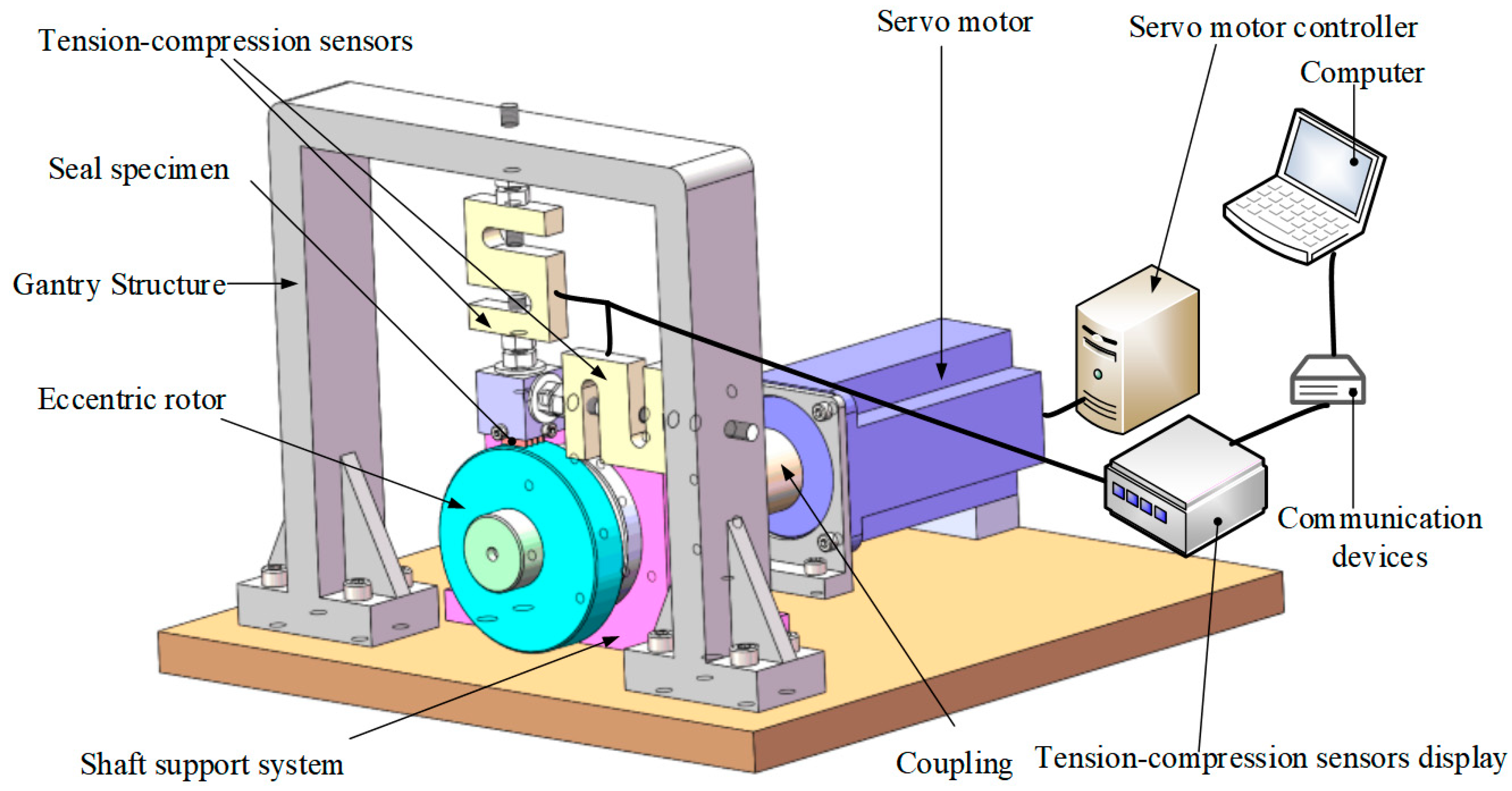
2.1. Design of the Rub-Impact Experimental System

Rub-impact between rotating shafts and sealing teeth is a major cause of increased leakage in labyrinth seals. To systematically investigate the leakage characteristics under such conditions, a custom rub-impact experimental system was developed to simulate real-world operational scenarios. This system employs an eccentric rotor to generate controlled rub-impact events, which enables a precise analysis of post-impact tooth deformation and its correlation with leakage dynamics.
The experimental setup uses a four-tooth straight-through trapezoidal seal structure (Figure 1), and single-tooth specimens are selected for focused testing.
The experimental system, as illustrated in Figure 2 and Figure 3, comprises a servo motor, a shaft support system, bellows flexible coupling, an eccentric rotor, a gantry structure, tension–compression sensors, a seal specimen, a display unit for the tension–compression sensors, and a computer. The functional specifications of each component are detailed as follows:
(1)
Servo Motor
Connected to the bellows flexible coupling, the servo motor provides stepless speed regulation within the range of 0–3000 revolutions per minute (RPM), enabling precise control over the rotational dynamics of the experimental setup.
(2)
Bellows Flexible Coupling
Interposed between the servo motor and the shaft support system, the bellows flexible coupling serves a dual role: it minimizes vibration transmission to enhance mechanical stability and compensates for radial misalignments between the motor and the shaft, thereby reducing dynamic stresses arising from geometric discrepancies.
(3)
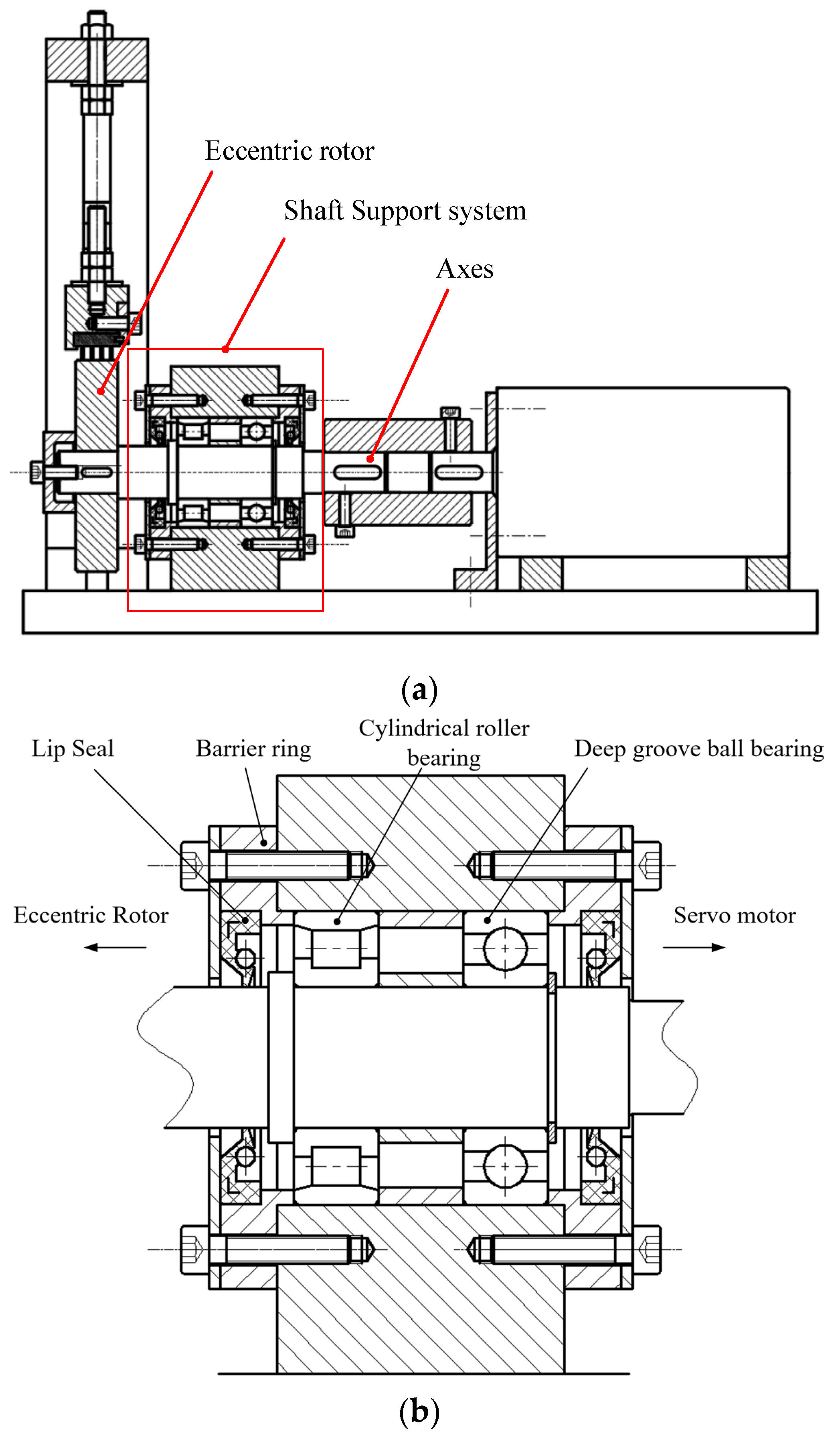
Shaft Support System
As depicted in Figure 4, the shaft support system employs a cantilever-beam configuration with the experimental section positioned externally to the main support structure. This design mitigates assembly errors during bearing installation/removal and facilitates the replacement of the eccentric bushing. To withstand radial loads generated during testing, a cylindrical roller bearing is utilized at the test end, while a deep-groove ball bearing is adopted at the motor end. Both bearings are lubricated with grease, and lip-shaped sealing rings are installed on the outer sides of the bearing housings to prevent lubricant leakage, ensuring long-term operational reliability.
(4)
Eccentric Rotor
Mounted on the extended end of the shaft support system, the eccentric rotor is positioned with a minimal axial distance from the support structure. This geometric arrangement is intended to suppress radial disturbances during rub-impact events, thereby enhancing the accuracy of force measurements.
(5)
Gantry Structure
Fixed to the experimental base, the gantry serves as the mounting framework for the tension–compression sensors, as shown in Figure 2. These sensors are configured to simultaneously measure radial impact forces and frictional forces, providing comprehensive data on the mechanical interactions between the rotor and the seal specimen. The tension and compression sensor used is a model LLBLS-1 with a measurement range of 30 kg (approximately 294 N) and a high accuracy of 0.03% FS (full scale).
(6)
Labyrinth Seal Specimen
The seal specimen is secured above the eccentric rotor by two tension–compression sensors oriented horizontally and vertically. During rotor–specimen collisions, these sensors capture both impact and frictional forces in real time. The vertical sensor, attached to the gantry via a threaded screw mechanism, allows for precise adjustment of the initial interference distance between the eccentric rotor and the specimen through incremental threading adjustments, enabling the controlled simulation of rub-impact conditions.
(7)
Data Acquisition and Monitoring
As shown in Figure 3, measurement data from the tension–compression sensors are displayed in real time on a dedicated monitor. Concurrently, impact and frictional force signals are acquired via a data acquisition card and transmitted to a computer for continuous monitoring and subsequent analysis (the signals were acquired at a sampling rate of 1 kHz), ensuring the seamless integration of experimental observations with data processing workflows.

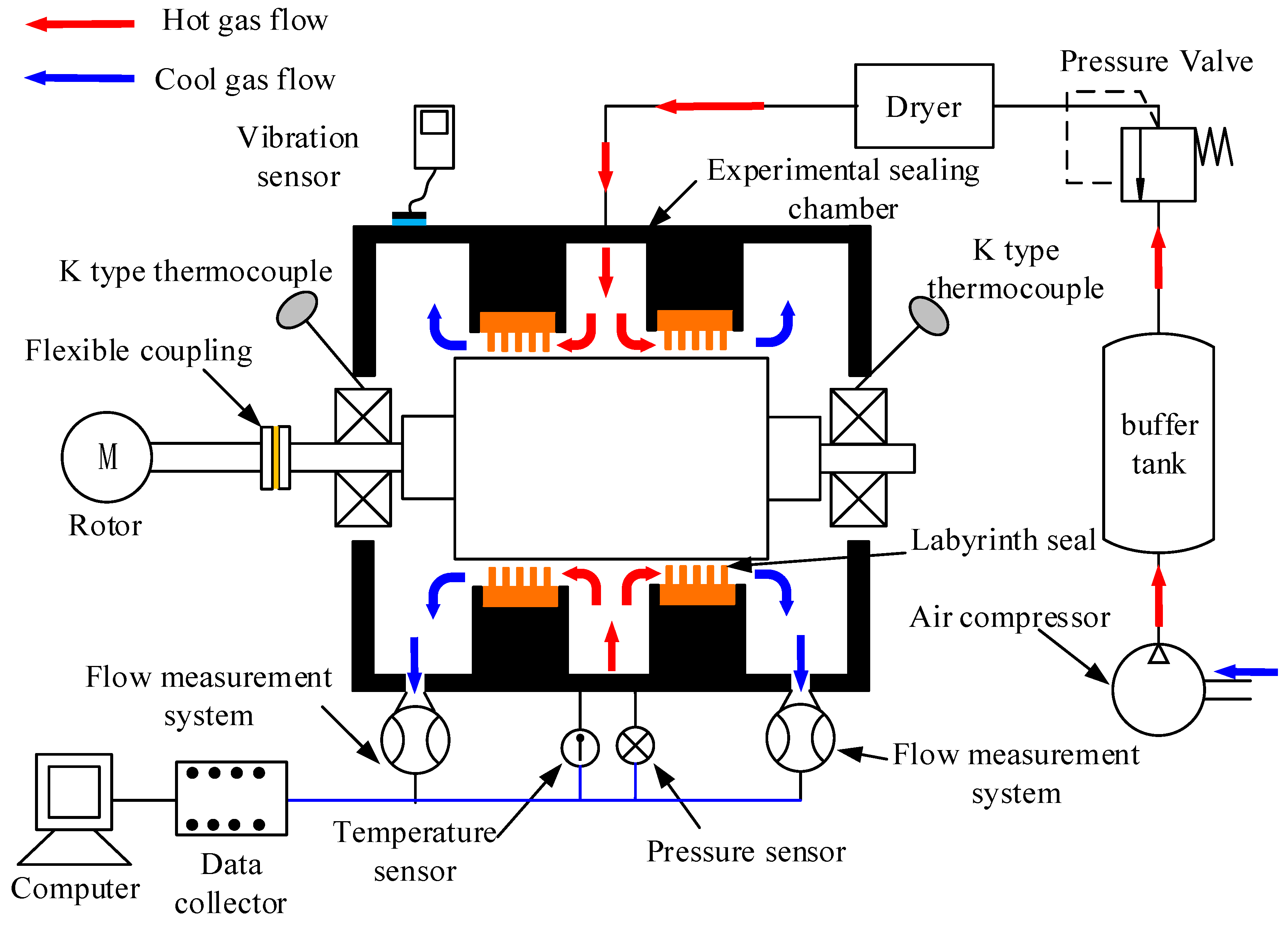
2.2. Labyrinth Seal Leakage Experimental System

The labyrinth seal low-pressure experimental system, shown in Figure 5, was utilized to measure leakage rates under various operating conditions. This system primarily comprises four main subsystems: an electric spindle system (for rotor rotation), an experimental seal chamber system (housing the seal specimens), a flow measurement system (to quantify leakage), and a gas supply system. This setup is capable of simulating labyrinth seal operating conditions up to a maximum inlet gauge pressure of 0.6 MPa and rotor speeds of 10,000 r/min. The experimental seal chamber employs a fully symmetric dual labyrinth seal design. This configuration effectively addresses potential axial pressure imbalance issues within the chamber and allows for comparative data acquisition from the two symmetrical seal sections, thereby aiding in the elimination of experimental errors. Compressed air is supplied by an air compressor with a maximum working gauge pressure of 1.2 MPa and a volumetric flow rate of 4.5 m3/min. To minimize excessive pressure drop along the supply line and ensure stable test conditions, a 1.0 m3 buffer tank was integrated between the compressor outlet and the experimental seal chamber. A pressure-regulating valve and a filter valve were installed downstream of the buffer tank to ensure controlled pressure and clean air supply to the seal chamber. More detailed descriptions of the experimental system setup, operation, and validation for leakage measurements can be found in reference [19].

3. Numerical Model

3.1. Material Properties

Employing wear-resistant and deformable polymer materials for seal rings represents a promising strategy to reduce the clearance of labyrinth seals. Thermoplastic polymers, such as PAI and PEEK, exhibit distinct advantages: their low elastic modulus allows elastic bending upon contact with rotating shafts, preventing shaft abrasion while maintaining sealing integrity. In contrast, conventional plastics like PTFE and F500, despite superior wear resistance, suffer from irreversible deformation due to their lower mechanical strength. This research systematically evaluates four materials (Table 1) through finite element analysis (FEA) to quantify their deformation behaviors under rub-impact.

3.2. Solid Finite Element Model

Static structural analysis was conducted in Abaqus/Standard (Abaqus 2020) to evaluate stress distribution and deformation under rub-impact loads. The model assumes quasi-static loading conditions, neglecting inertial and damping effects, as validated by prior studies [29]. The governing equation for structural deflection is expressed as shown below:
σ = ( D ) ε el
ε el = B u ε th
where σ is the stress vector, D is the elasticity matrix, B is the strain–displacement matrix evaluated at integration points, u is the nodal displacement vector, ε e l is the elastic strain and ε t h is the thermal strain.
Model Setup:
(1)
Boundary conditions replicated experimental constraints with three fixed surfaces on the seal specimen (Figure 6).
(2)
Material properties (Table 1) were imported from uniaxial compression tests. Plasticity models for PAI, PEEK, PTFE, and F500 were applied with the plastic constitutive behavior defined using tabular stress–plastic strain data derived from these experimental tests.
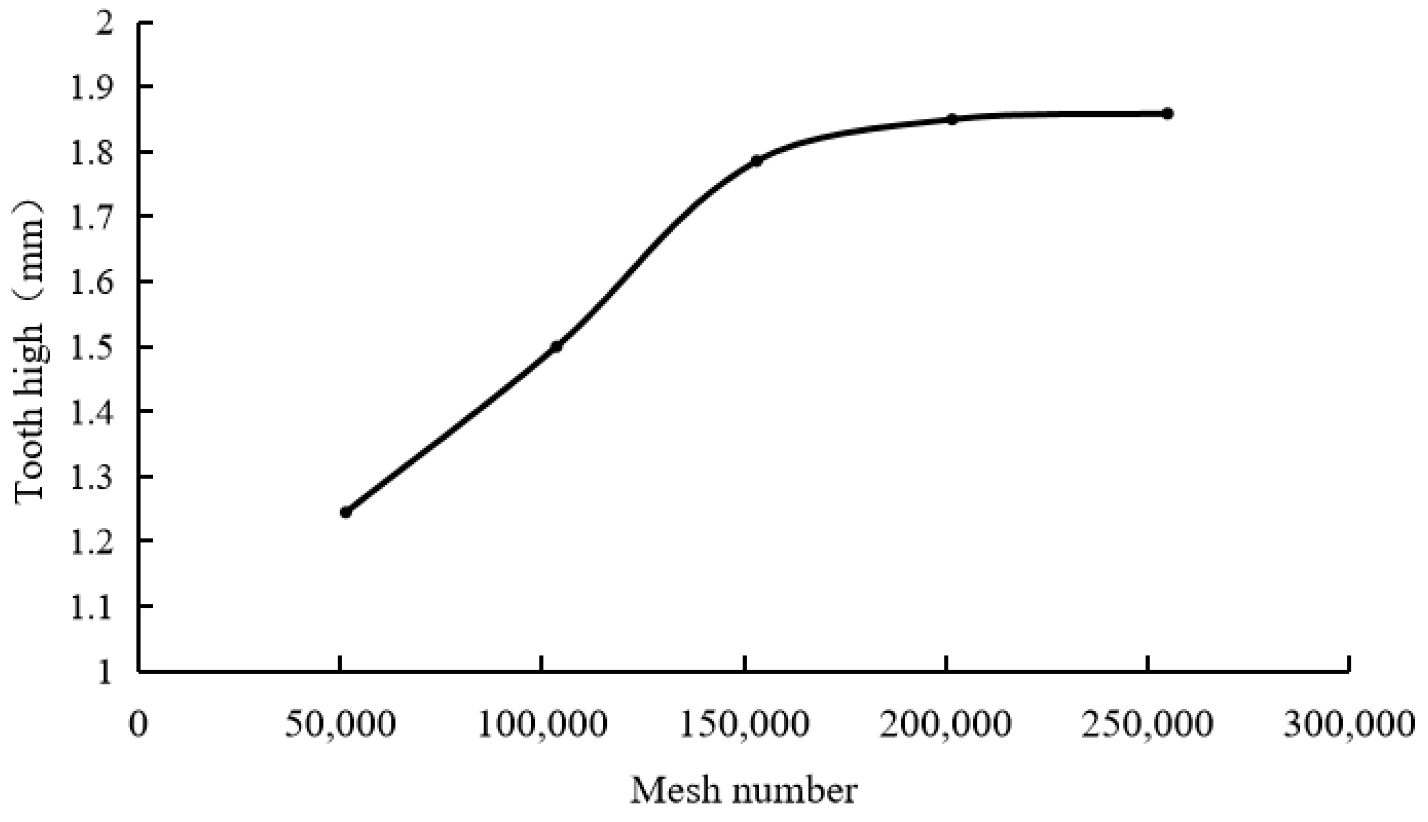
(3)
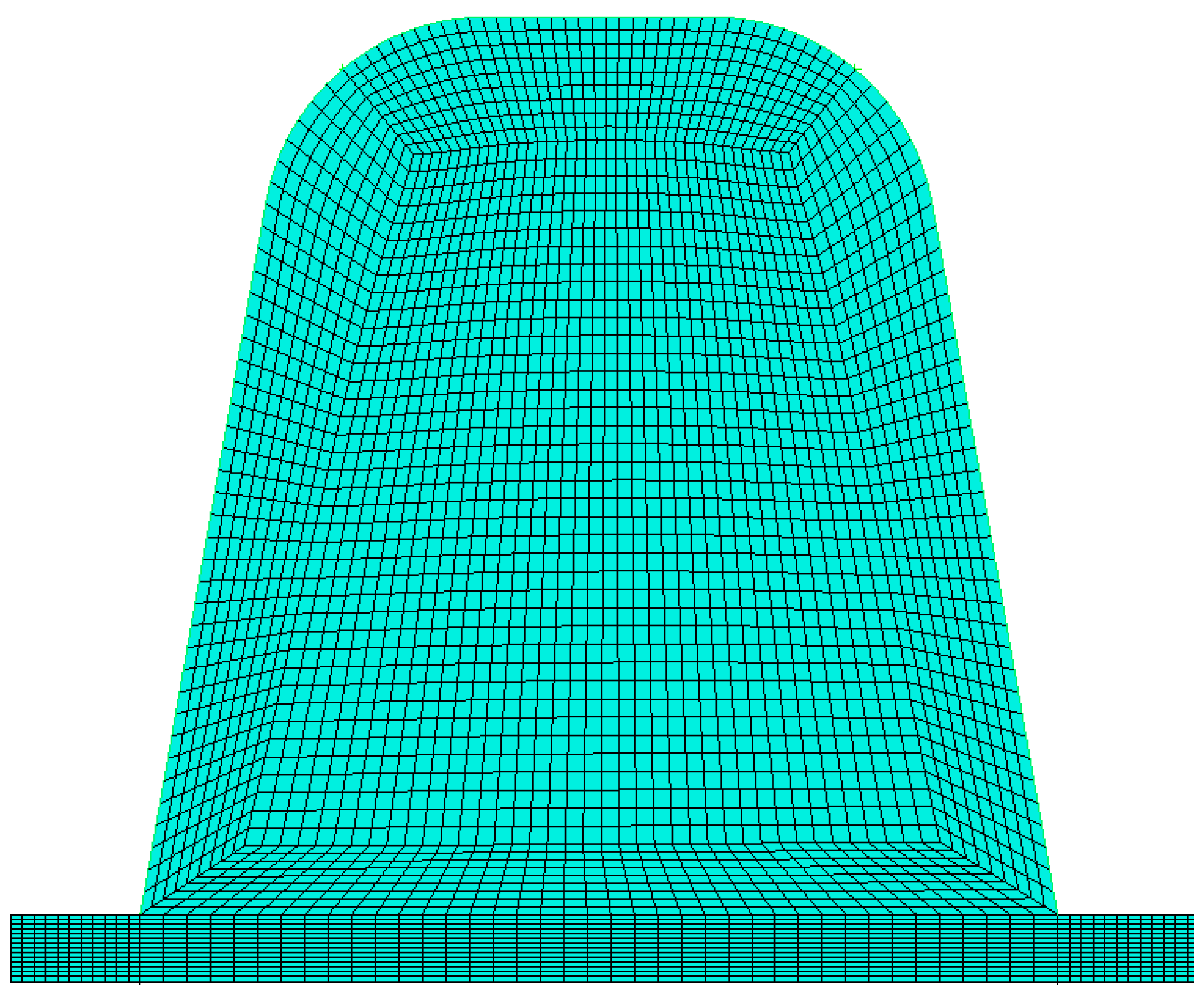
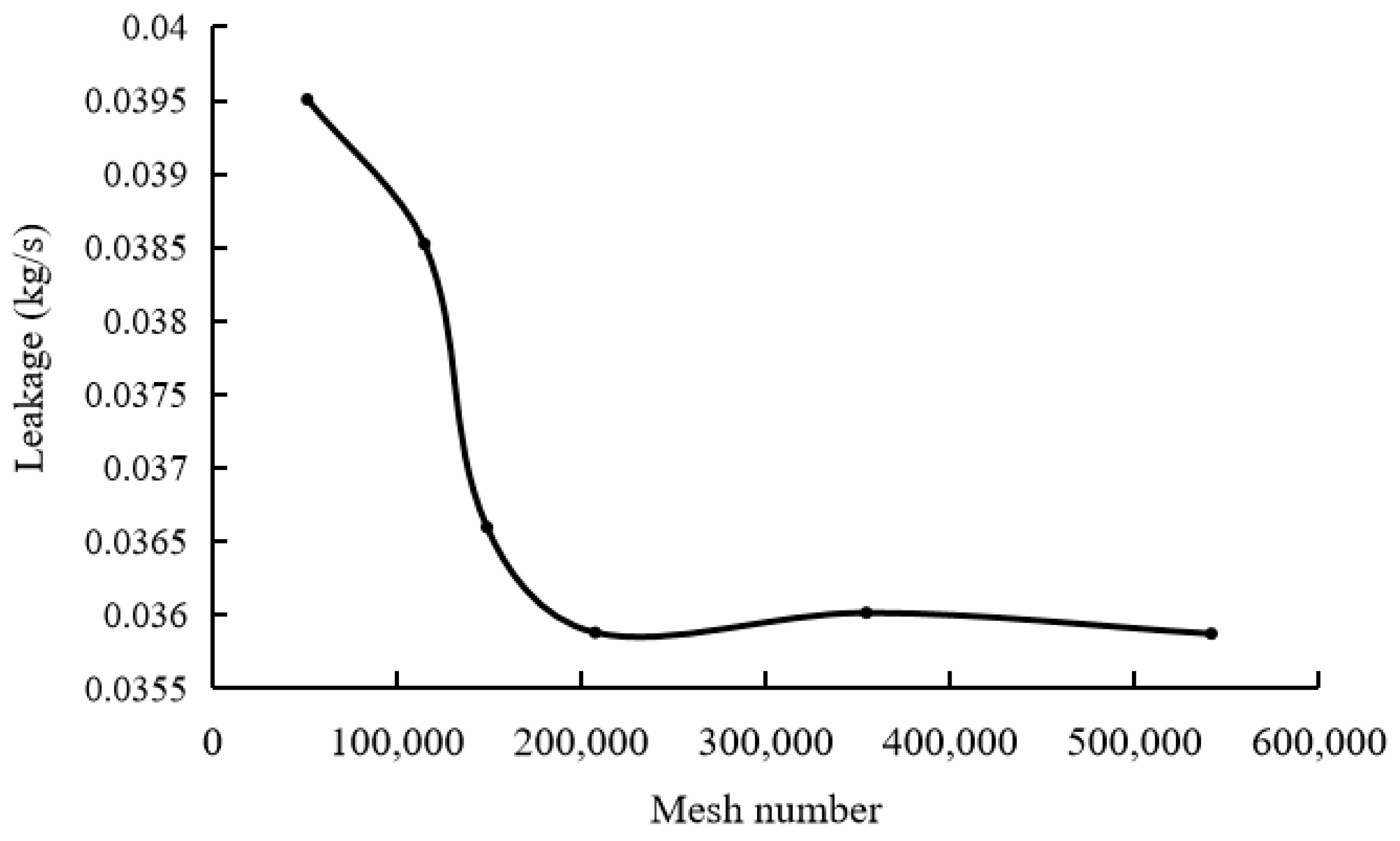
Mesh sensitivity analysis: Mesh sensitivity analysis was conducted using PTFE material, selecting the post-impact tooth height as the convergence criterion. As shown in Figure 7, the results indicate that when the number of elements is approximately 254,000 (corresponding to an average element size of 0.05 mm), the post-impact tooth height converges to a stable value. Therefore, an average element size of 0.05 mm was adopted for all subsequent FEA calculations in this study, resulting in a model with approximately 254,000 tetrahedral elements.

3.3. CFD Model Development

The internal flow field of the labyrinth seal was simulated using a validated CFD model based on the compressible Navier–Stokes equations while neglecting body forces and assuming ideal gas behavior. This axisymmetric approach effectively simulates the 3D rotational flow through the annular seal passages, and comprehensive details regarding this model’s setup, validation, and grid parameters are available in our previous publications [29,30]. The density (p) is defined as shown below:
ρ = p M w R T
where p is the pressure, Mw is the gas molecular weight, R is the universal gas constant, and T is the temperature. The conservation equations are outlined below:
ρ v = 0
ρ ρ v v = p + ( τ ) + S M
ρ v h t o t = ( λ T + v ( τ ε ) ) + v S M + S E
where τ is the stress tensor, v is the velocity vector, p is the pressure, htot is the total enthalpy, and SM, SE represent momentum and energy source terms.
Given the high Reynolds number (Re > 2000) in seal clearances, the standard k-ϵ turbulence model was adopted. The turbulent kinetic energy (k) and dissipation rate (ϵ) are governed by the following:
( ρ k v ) = ( ( μ + μ t σ k ) k ) + G K + G b ρ ε Y M + S k
( ρ ε v ) = ( ( μ + μ t σ ε ) ε ) + C 1 ε ε k ( G K + C 3 ε G b ) C 2 ε ρ ε 2 k + S ε
where GK represents the turbulent kinetic energy generated due to the average velocity gradient; Gb represents the turbulent kinetic energy generated by buoyancy, and YM represents the effect of wave expansion in compressible turbulence on the total dissipation rate. μt (=ρCμk2/ε) represents turbulent viscosity, while Sk and Sε are the source terms for the turbulent kinetic energy and dissipation rate. Constants include C1ε (=1.44), C2ε (=1.92), C3ε (=1.3) and Cμ (=0.09).
Boundary conditions were set according to experimental measurements [29,30] (Table 2).
Inlet/Outlet: pressure boundaries (Pin = 0.25 MPa, Pout = 0.1 MPa).
Turbulence Model: standard k-ϵ with scalable wall functions (y + <30).
Solver: SIMPLEC algorithm with second-order upwind discretization, achieving residuals < 1 × 10⁻⁶.
The meshing was performed using commercial software (e.g., ANSYS ICEM CFD 2021), employing structured grid techniques including O-block for complex geometries, as shown in Figure 8. Crucially, the clearance gaps were resolved with 15 layers of grid cells, and mesh independence analysis was performed to ensure grid sensitivity was minimal. Near-wall regions were handled using scalable wall functions, targeting a y+ value suitable for this approach (<30).
A mesh independence study was conducted to ensure that the CFD results were not significantly affected by the grid resolution. The total leakage rate was selected as the target parameter for this analysis. As illustrated in Figure 9, the calculated leakage rate converged as the mesh density increased, showing negligible variation once the number of elements reached approximately 540,000. Specifically, the change in leakage rate was less than 2% beyond this grid density. Based on these results, the mesh strategy corresponding to a total element count of approximately 540,000 (as exemplified in Figure 8, which shows the mesh detail) was deemed sufficient to achieve mesh independence and was adopted for all subsequent CFD calculations.
The four-tooth straight-through labyrinth seal structure, depicted in Figure 1, was selected as the geometry for the CFD analysis. Considering that eccentric rub-impact, when viewed over a full rotation, tends to induce a circumferentially consistent deformation and wear pattern on the seal ring, the resulting annular flow passages exhibit rotational periodicity. Therefore, the complex three-dimensional flow field through the seal could be effectively simplified to a two-dimensional axisymmetric formulation for computational analysis.
This was achieved in ANSYS Fluent (Version 2021) by setting the 2D computational domain to an ‘Axisymmetric’ model (Figure 10). This 2D model simulates the 3D annular flow field by revolving the 2D geometry around the Y-axis, which was aligned with the labyrinth seal’s centerline during setup. This approach effectively captures the essential physics of the flow through the annular labyrinth seal passages while significantly reducing computational cost compared to a full 3D model. Consequently, the results obtained from this 2D axisymmetric simulation represent the total mass flow rate for the entire 3D annular seal.
A representative 2D flow field contour for the original, undeformed seal structure is shown in Figure 10a, illustrating the pressure distribution within the passages (red indicates high pressure, blue indicates low pressure). To analyze the impact of tooth deformation on leakage, the post-rub-impact tooth profiles obtained from the FEA simulations were accurately reconstructed using CAD software to create the deformed CFD models.
Due to varying inflow conditions and structural design requirements in practical applications, the bent seal tooth after deformation can interact with the gas flow in different orientations relative to the flow direction. Consequently, two distinct CFD model configurations were analyzed based on the deformed tooth shapes derived from FEA, as schematically illustrated in Figure 10b,c. The initial seal clearance in the CFD model is 0.15 mm, and the actual clearance after rub-impact is the sum of the initial clearance and the reduction in tooth height.
(1)
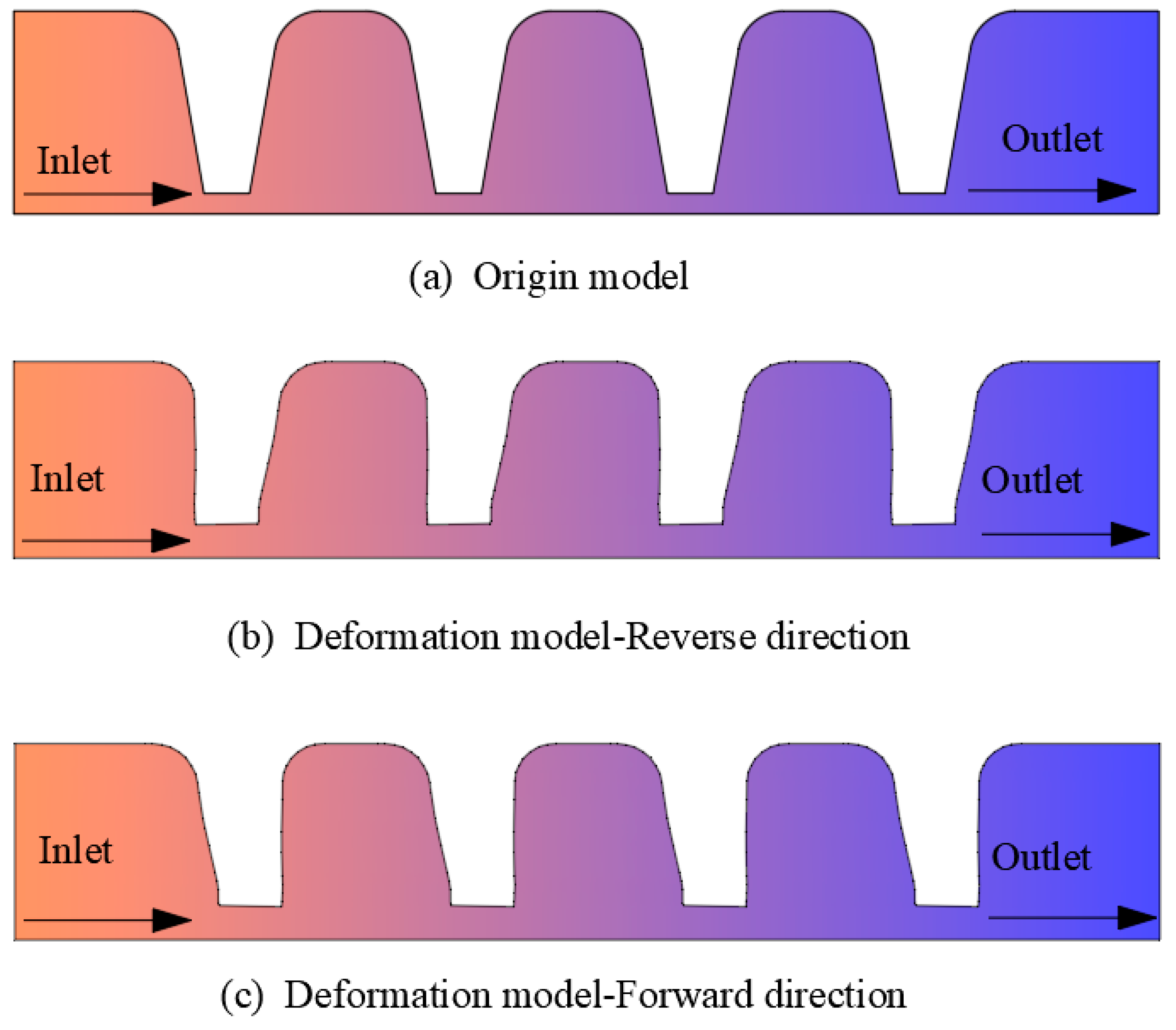
Forward Flow: The direction of gas flow is aligned with the primary bending direction of the seal tooth profile.
(2)
Reverse Flow: The direction of gas flow is opposed to the primary bending direction of the seal tooth profile.
For the CFD analysis, the specific deformed geometries were derived directly from the post-rub-impact tooth profiles obtained from the FEA results. These deformed profiles were used to reconstruct the geometry for the CFD models shown schematically in Figure 10b,c. The multi-tooth model assumed uniform deformation across all teeth, which was validated against single-tooth simulations.

4. Results and Discussion

4.1. Comparative Analysis of Simulation and Experimental Results

To validate the FEA model, simulated tooth deformations under mild rub-impact (0.25 mm interference) were compared with experimental measurements (Figure 11). The average post-impact tooth height discrepancy was 5.1% (simulation: 1.81 mm vs. experiment: 1.73 mm), which was within acceptable error margins for thermoplastic behavior prediction. Stress–strain curves further confirmed that 92% of the deformation resulted from plastic yielding (Figure 11), aligning with the dominance of impact forces in early-stage rub-impact.
Notably, the model underestimated tip widening by 3–6%, which was likely due to omitted abrasive wear effects in the static FEA framework. This limitation highlights the need for coupled wear-deformation modeling in future studies.
To validate the accuracy of the developed CFD flow field model, simulations were conducted for the original, undeformed four-tooth straight-through labyrinth seal geometry (as represented by the CFD model shown in Figure 10a) with a fixed clearance of 0.15 mm across a range of pressure differences.
The calculated leakage rates, presented in Figure 12, demonstrate a direct proportionality with the total pressure difference across the seal. A comparative analysis against experimental leakage measurements revealed a maximum discrepancy of 3% between the numerical predictions and experimental data. This close agreement confirms the accuracy and reliability of the CFD flow field model for simulating leakage characteristics under the specified operating conditions, providing confidence in its application for analyzing flow through the deformed seal geometries.

4.2. Rub-Impact Experimental Results Analysis
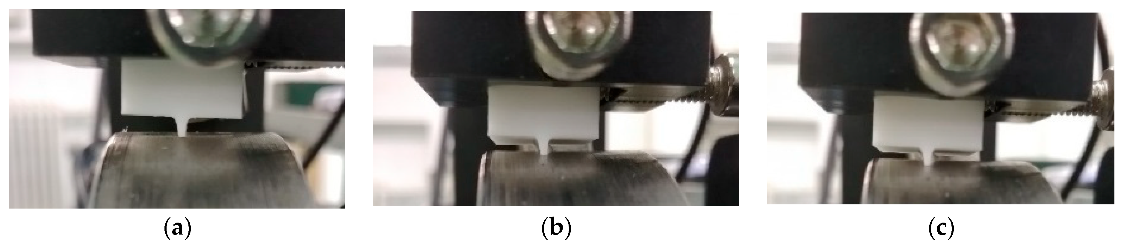
The experimental specimen had a trapezoidal sealing-tooth structure, as shown in Figure 13a–c. High-speed imaging (1000 fps) captured a complete rub-impact cycle. Three distinct deformation phases were observed:
(1)
Elastic Bending Phase: Initial rub-impact induced pronounced bending of the sealing teeth (Figure 13b); impact force as the dominant factor.
(2)
Progressive Wear Phase: Repeated collisions flattened the tooth tip, transitioning the dominant mechanism from impact to sliding friction.
(3)
Termination Phase: Wear reduced the tooth height until contact ceased (impact force < 0.5 N), marking the end of the rub-impact process (Figure 13c).
Controlled wear was achieved by varying the initial interference (0.1–0.4 mm) and rotor speed (500–2500 RPM). Notably, higher speeds accelerated wear with the test duration reduced by 60% at 2500 RPM compared to 500 RPM. Post-test microscopy captured representative shapes of the sealing teeth after different levels of rub-impact induced wear (Figure 14). These shapes correspond to tooth height reductions of approximately 20%, 30%, and 40% under conditions resulting in mild, moderate, and severe rub-impact wear, respectively. Observations also showed the tip width increased by 15–45% depending on the wear severity.

4.3. Solid Finite Element Analysis
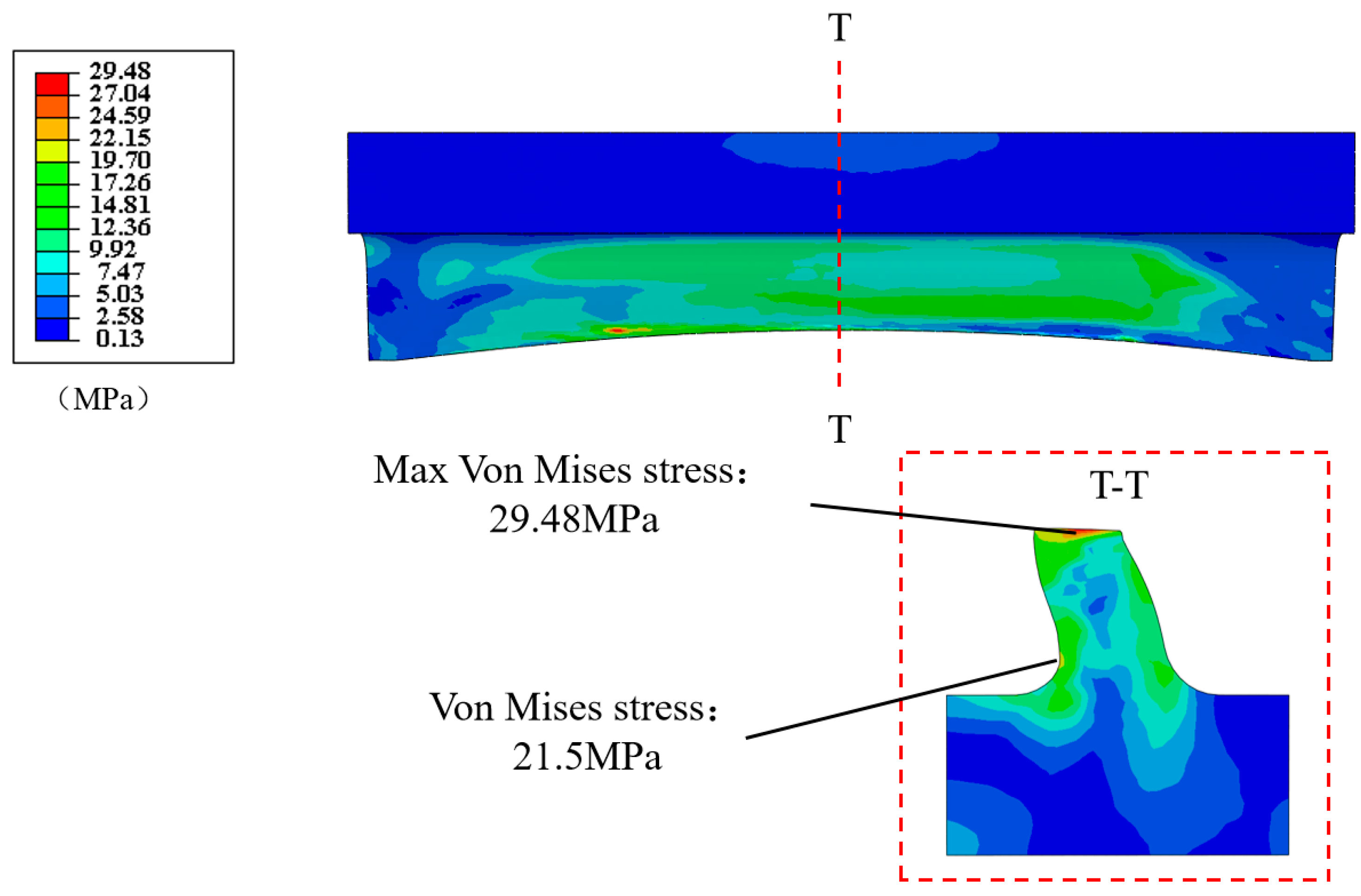
Static structural simulations in Abaqus/Standard elucidated stress distribution and deformation patterns under rub-impact loads. As shown in the cross-sectional view in Figure 15, the Mises stress distribution highlights concentrations primarily at two critical locations: the tooth tip, which is directly impacted by the rotor, and the tooth root, which is subjected to bending stress. This pattern, with high stress at the tip and significant stress at the root (approximately 21.5 MPa), is consistent with prior findings on thermoplastic deformation [29,30] and validates the dual-loading effect of impact and friction discussed in the cross-sectional analysis presented in Figure 16.
Key deformation characteristics include the following:
(1)
Tooth Bending: dominant in low-interference conditions (0.1–0.2 mm), causing 5–10% height reduction.
(2)
Tip Mushrooming: observed at higher interference (0.3–0.4 mm) with tip width expanding by 25–40%.
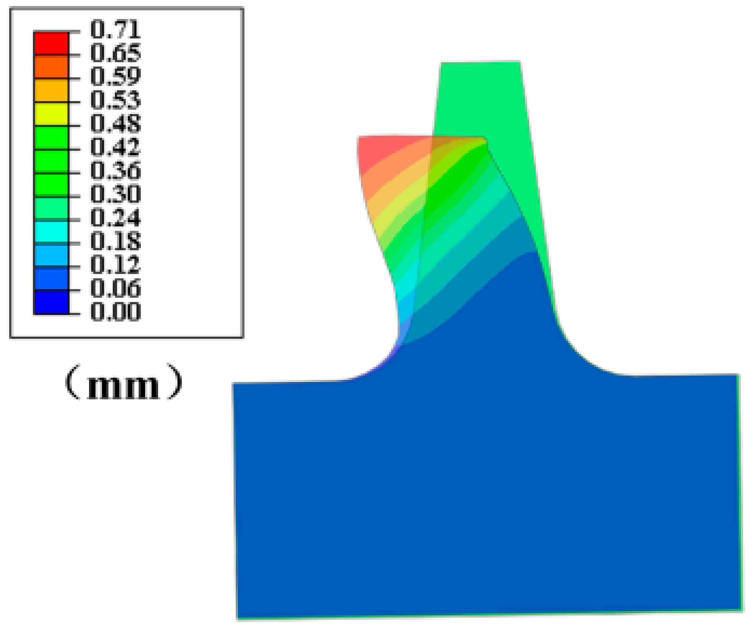
(3)
Microscopic Tilting: A 2–5° tilt was observed at the tooth tip (Figure 15). In the FEA simulation, this tilting is attributed to the development of asymmetric contact forces and frictional resistance across the tooth tip surface during the rub-impact and sliding phase, which is a phenomenon consistent with real-world asymmetric contact conditions arising from factors like rotor eccentricity, seal movement, and manufacturing variations.

4.4. Leakage Rate Analysis

Leakage rates were obtained from the CFD simulations by integrating the mass flow rate across the outlet boundary of the computational domain. Due to the 2D axisymmetric nature of the model, this integral represents the total mass flow rate through the full 3D annular seal. The calculated leakage rate for the original, undeformed seal structure with 0.15 mm clearance was 0.035 kg/s at 0.25 MPa pressure difference. As shown in Figure 17, these leakage rates increased linearly with interference due to enlarged clearances. The severity of this increase was material-dependent; at the maximum tested interference of 0.25 mm and under reverse flow conditions, the leakage rates for all materials significantly increased compared to the original state (0.035 kg/s). Specifically, PTFE showed a 217% increase (resulting in 0.111 kg/s), F500 a 214% increase (0.110 kg/s), PEEK a 186% increase (0.100 kg/s), and PAI a 151% increase (0.088 kg/s). At 0.25 mm interference:
(1)
PAI exhibited the lowest post-impact leakage (0.088 kg/s at 0.25 mm interference, reverse flow), which was approximately 20% less than PTFE (0.11 kg/s).
(2)
Reverse flow generally resulted in slightly lower leakage (0.5–3% reduction) compared to forward flow for the same material and interference, which was attributed to enhanced vena contracta effects (Figure 18).
The vena contracta effect—where fluid streamlines contract at narrow passages—dominated leakage behavior. In reverse flow, strong contraction at the tooth tip created a vortex zone (Figure 18), effectively reducing the clearance by 15–20%. Forward flow weakened this effect, increasing the effective clearance and leakage by 0.5–3%. Material properties further modulated these trends: PAI/PEEK: minimal tip widening (<20%) preserved vena contracta, limiting leakage. PTFE/F500: Severe mushrooming (>35%) disrupted streamline contraction, exacerbating leakage.
By analyzing the flow field of sealing teeth made of different materials, it can be concluded that the increase in sealing clearance after rubbing is the main reason for the increase in leakage. Secondly, the bending direction of the tooth profile after rubbing will further affect the change in leakage.

5. Deformation Mechanisms of Sealing Teeth

5.1. Influence of Interference and Frequency on Deformation

The deformation of sealing teeth is governed by two critical operational parameters: interference (0.05–0.25 mm) and impact frequency (0.83–13.33 Hz). Key mechanisms include the following:
(1)
Interference-Driven Deformation: Shaft eccentricity or vibration reduces the clearance between rotating and stationary components, inducing localized stress concentrations.
(2)
Frequency Independence: FEA results (Figure 19) revealed negligible differences in tooth deformation across frequencies (0.83–13.33 Hz) with <3% variation in tip height.

5.2. Material-Specific Deformation Patterns
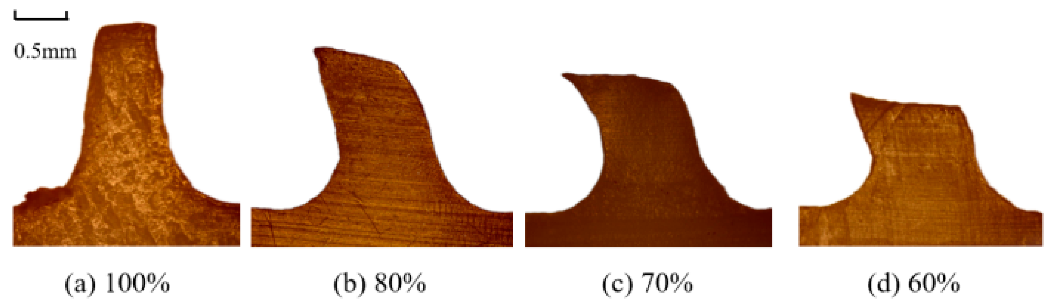
Figure 20 illustrates the deformation trends of four materials under varying interference levels (constant frequency: 3.33 Hz):
(1)
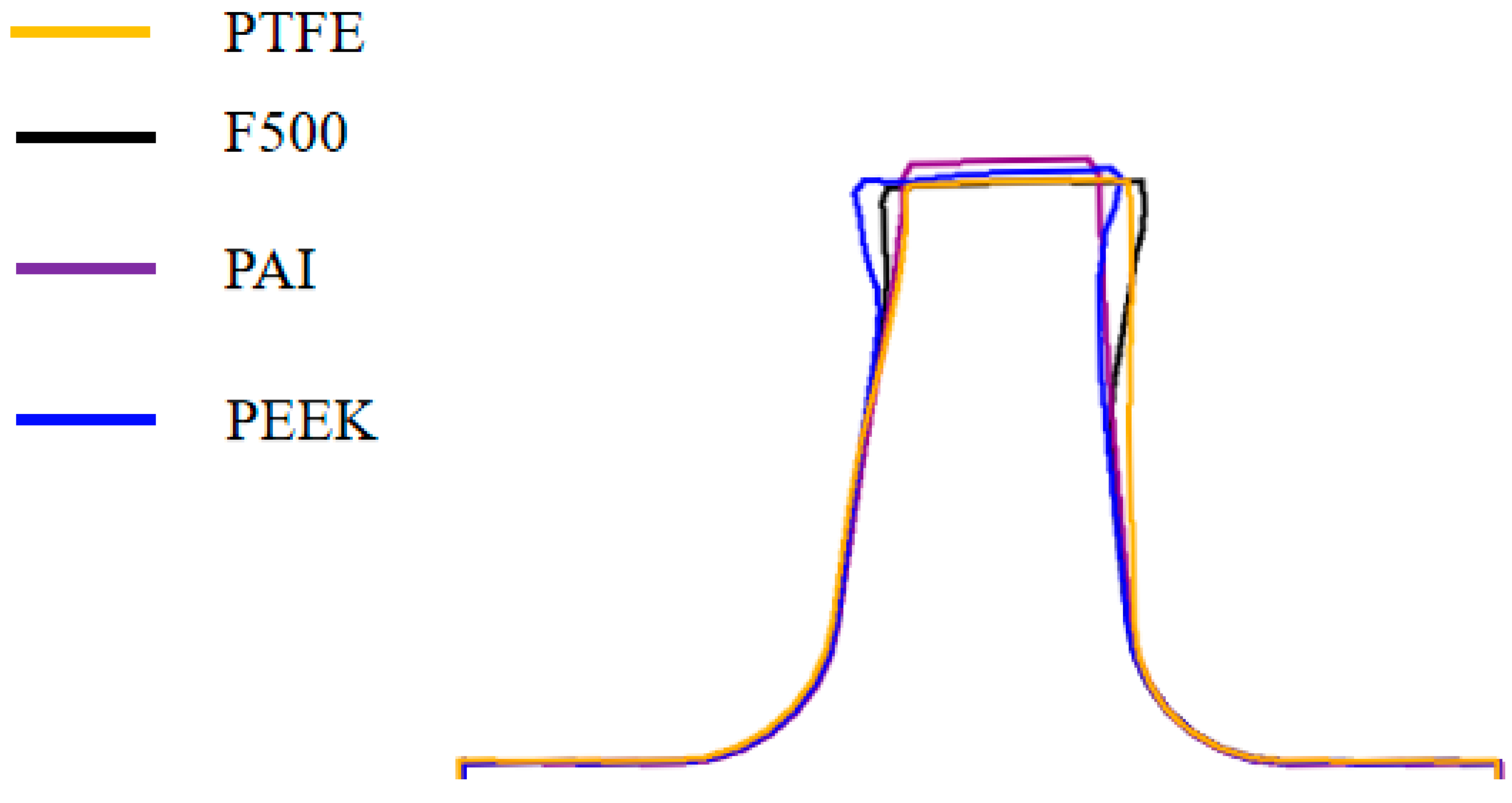
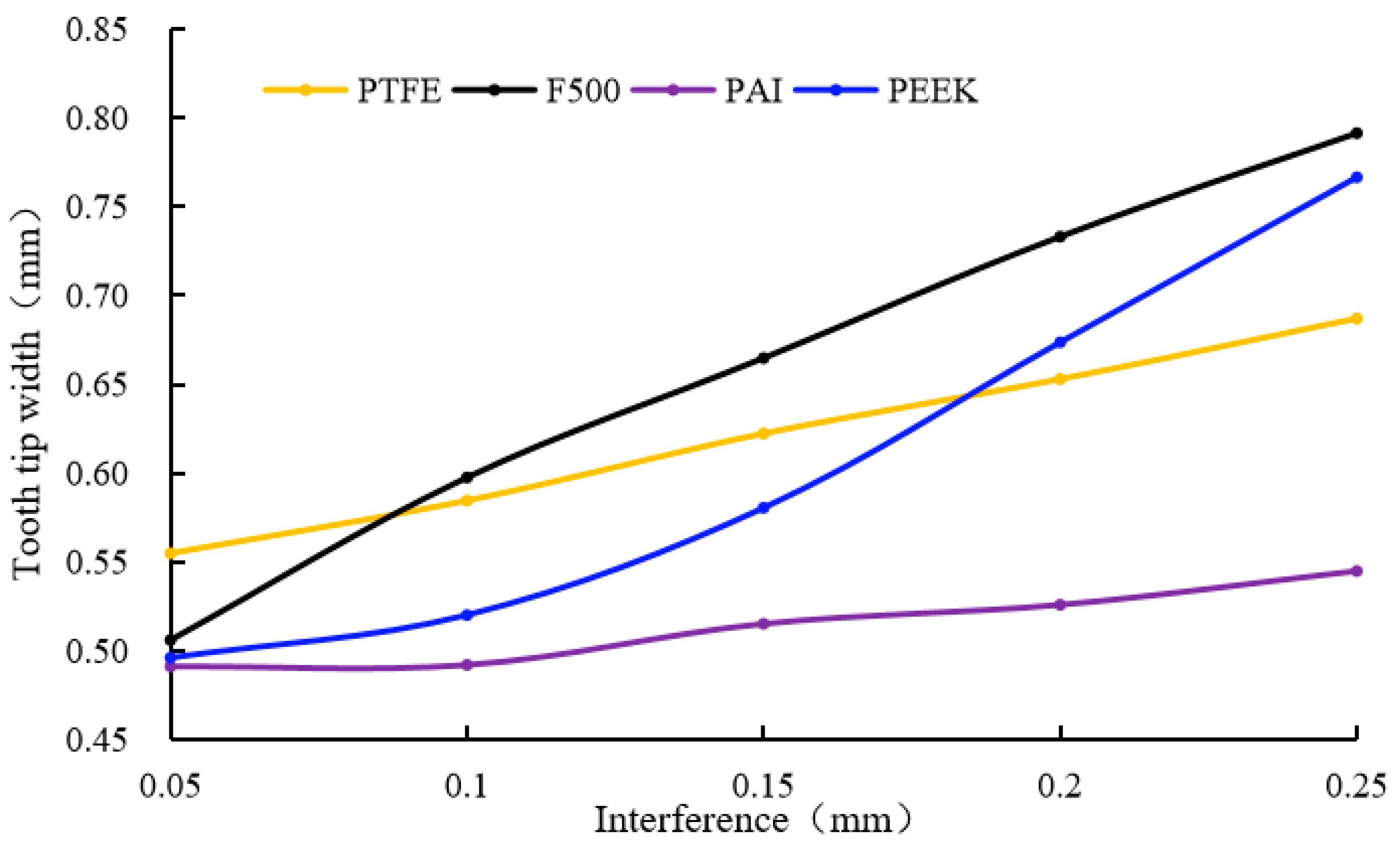
Low-Strength Materials (PTFE, F500): exhibited progressive bending (height reduction: 1.3–12%) and severe tip mushrooming (width expansion: 2–60%) due to plastic yielding (Figure 20a,b).
(2)
High-Strength Thermoplastics (PAI, PEEK): demonstrated elastic-dominated deformation with limited bending (<9% height loss) and moderate tip widening (2–50%) even at 0.25 mm interference (Figure 20c,d).
A comparative analysis under the same conditions (0.25 mm interference, 3.33 Hz, initial clearance 0.15 mm) further highlighted the performance differences among materials (Figure 21):
(1)
PAI achieved the minimal clearance (0.29 mm vs. initial 0.15 mm), whereas PTFE and F500 suffered 150% greater clearance enlargement.
(2)
Tip width expansion followed the order: F500 (+58.2%) > PEEK (+53.4%) > PTFE (+37.4%) > PAI (+9%).

5.3. Rebound Ratio and Leakage Correlation

To quantify resilience, a dimensionless rebound ratio ( φ ) was defined:
φ = 1 h o h d i × 100 %
where ho is the initial tooth height (2.0 mm), hd is the deformed height, and i is the interference, as shown in Figure 22:
PAI maintained stable rebound ratios (43.6–57%) across interference levels, outperforming PEEK (28.7–70.3%), PTFE (10.2–35.8%), and F500 (14.5–50.5%).
As shown in Figure 23, tip widening correlated inversely with φ , confirming that materials with higher rebound ratios better preserved sealing geometry.
In summary, this section systematically investigated the deformation mechanisms of labyrinth seal teeth subjected to rub-impact, focusing on the critical roles of material properties and interference level. The finite element analysis revealed that rub-impact induces complex deformation patterns, including elastic bending, localized plastic yielding, tip mushrooming (tip widening), and microscopic tilting, with the severity heavily dependent on the initial interference. Crucially, the choice of material significantly influences the deformation response. Comparative analysis demonstrated that high-strength thermoplastics, specifically PAI and PEEK, exhibit superior resilience characterized by higher rebound ratios and less severe permanent plastic deformation (lower tip widening) compared to conventional plastics like PTFE and F500 under identical rub-impact conditions. These findings highlight that the resulting post-impact tooth geometry, particularly the remaining tooth height (which directly controls the seal clearance) and the extent of tip widening (which affects flow channeling), are the dominant factors determining the degradation of sealing performance. The ability of thermoplastics to better maintain minimal post-impact clearance and limit tip distortion thus underscores their significant advantage for applications where seals are subjected to dynamic rub events.

6. Optimization Design and Performance Validation

6.1. Design Rationale and Structural Innovation

Based on the deformation mechanisms identified in Section 5, PAI was selected as the optimal material for geometric optimization due to its excellent resilience and leakage-resistance under rub-impact. Two novel inclined-tooth geometries were proposed (Figure 24):
Opt1: a horizontal-tip design with a 25° tilt angle is employed to enhance elastic recovery.
Opt2: a modified version of Opt1 featuring a 7° angled tip to stabilize post-impact clearance.
The inclined orientation aligns the teeth with the gas inflow direction, leveraging the vena contracta effect identified in Section 4.4 to minimize effective clearance.

6.2. Finite Element Validation

Static structural simulations under identical rub-impact conditions (interference: 0.25 mm; frequency: 3.33 Hz) revealed significant performance advantages:
Rebound Ratio: Opt1 achieved a 72% rebound ratio, outperforming Opt2 (64%) and the origin design (43%). This difference in elastic recovery is attributed to the distinct contact mechanics and resulting localized plastic deformation influenced by their specific tip geometries, as illustrated by contact regions A and B in Figure 25. Despite its slightly lower rebound, Opt2 still demonstrates significantly improved resilience (48.8% improvement over origin) and achieves comparable leakage reduction, as discussed in Section 6.3.
Stress Distribution: Opt2’s angled tip reduced von Mises stress at the tip by 32.4% (98 MPa vs. 145 MPa in the origin), and the von Mises stress at the tooth root also reduced. However, the von Mises stress at the tooth root and tip of Opt1 has increased (Figure 25).

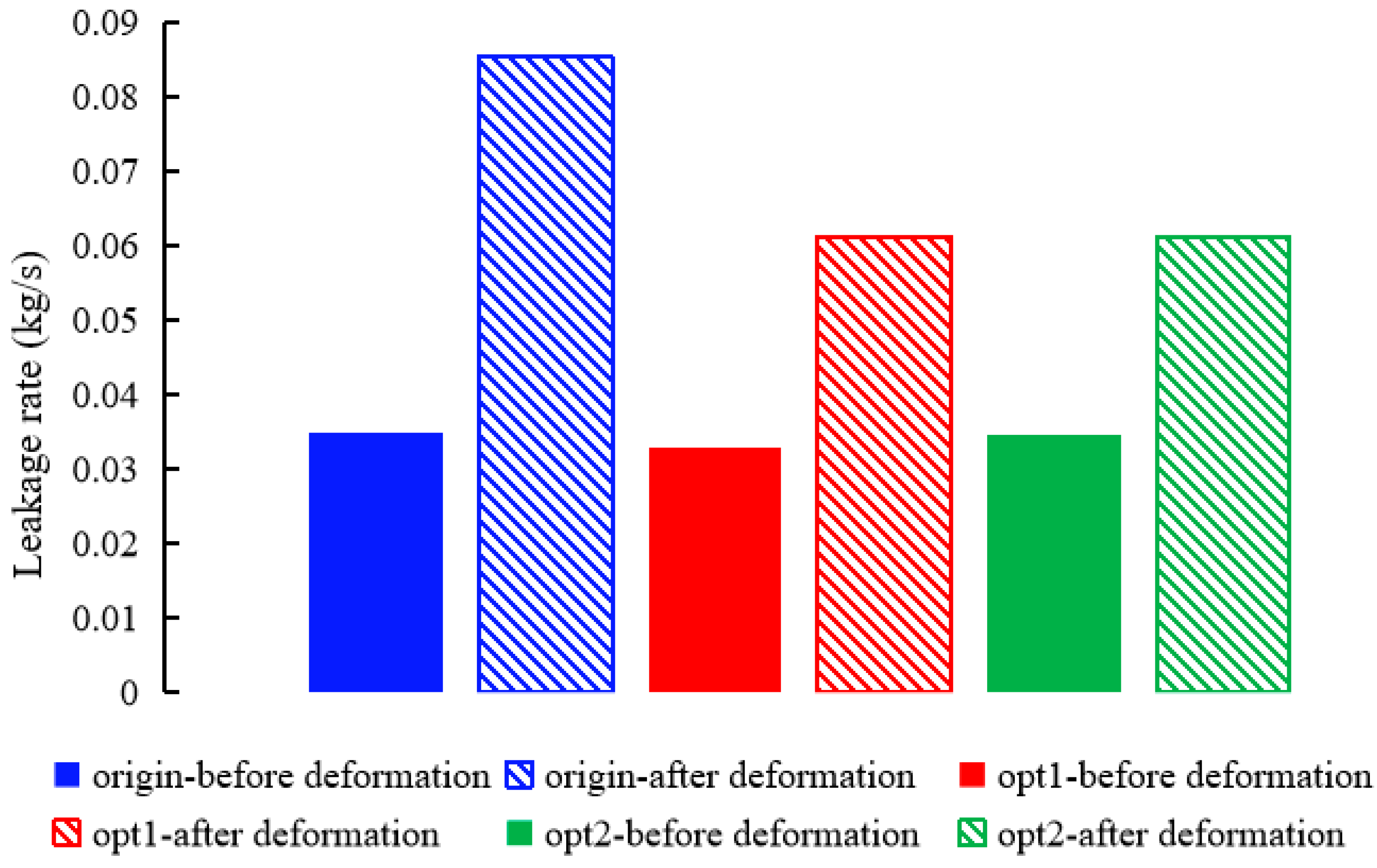
6.3. Leakage Performance Evaluation

CFD simulations compared leakage rates across three configurations: origin, Opt1 and Opt2 (Figure 26). Key findings include the following:
Undeformed State: Optimized geometries showed negligible leakage differences (<3%) compared to the origin, confirming minimal geometric disruption.
Post-Rub-Impact:
Opt1 reduced leakage by 28.2% (0.0613 kg/s vs. 0.085 kg/s for the origin).
Opt2 achieved a 28.1% reduction (0.06 kg/s), demonstrating robustness despite its lower rebound ratio.

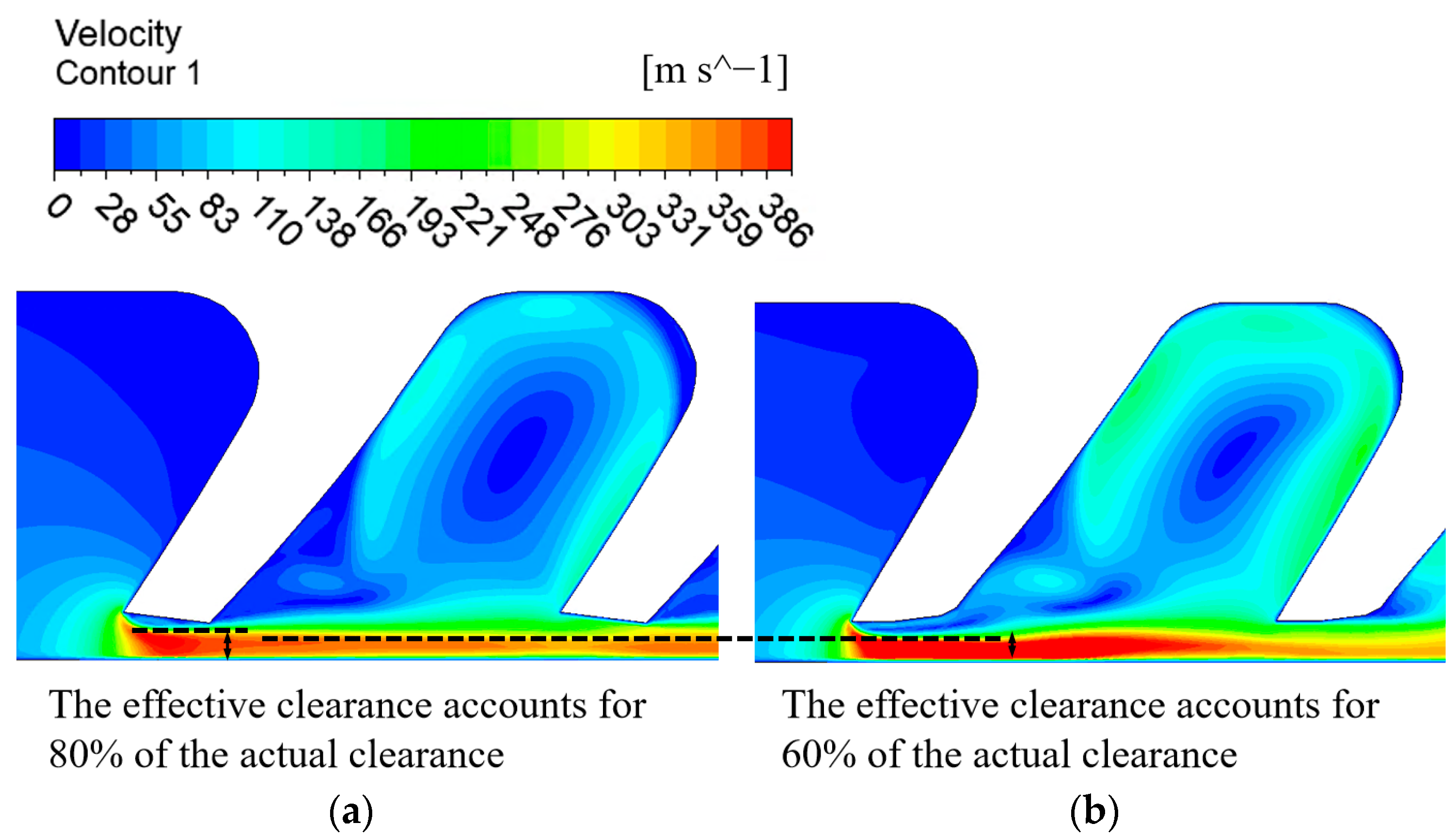
6.4. Analysis of Causes for Leakage Reduction

The leakage reduction stems from two synergistic effects:
Enhanced Vena Contracta: Inclined teeth strengthened streamline contraction at the tip, reducing effective clearance by 20–40% (Figure 27).
Deformation Control: Opt1’s horizontal tip limited post-impact tip widening, while Opt2’s angled design stabilized clearance via redirected bending (Figure 24).
These results validate that inclined-tooth geometries mitigate the trade-off between resilience and leakage, addressing a longstanding limitation in labyrinth seal design.

7. Conclusions

This study comprehensively investigated the complex interplay between rub-impact, tooth deformation, and leakage characteristics in thermoplastic labyrinth seals, employing an integrated experimental and numerical approach. The research aimed to elucidate the underlying deformation mechanisms, correlate them with leakage performance, and leverage these insights for high-efficiency seal optimization under rub-impact conditions.
(1)
A key contribution is the successful development and utilization of a novel custom rub-impact test system. This experimental rig enabled the simulation of dynamic rotor–seal interactions and the precise quantification of contact forces under controlled interference levels (0.05–0.4 mm), providing valuable data on the rub-impact process and resulting tooth deformation.
(2)
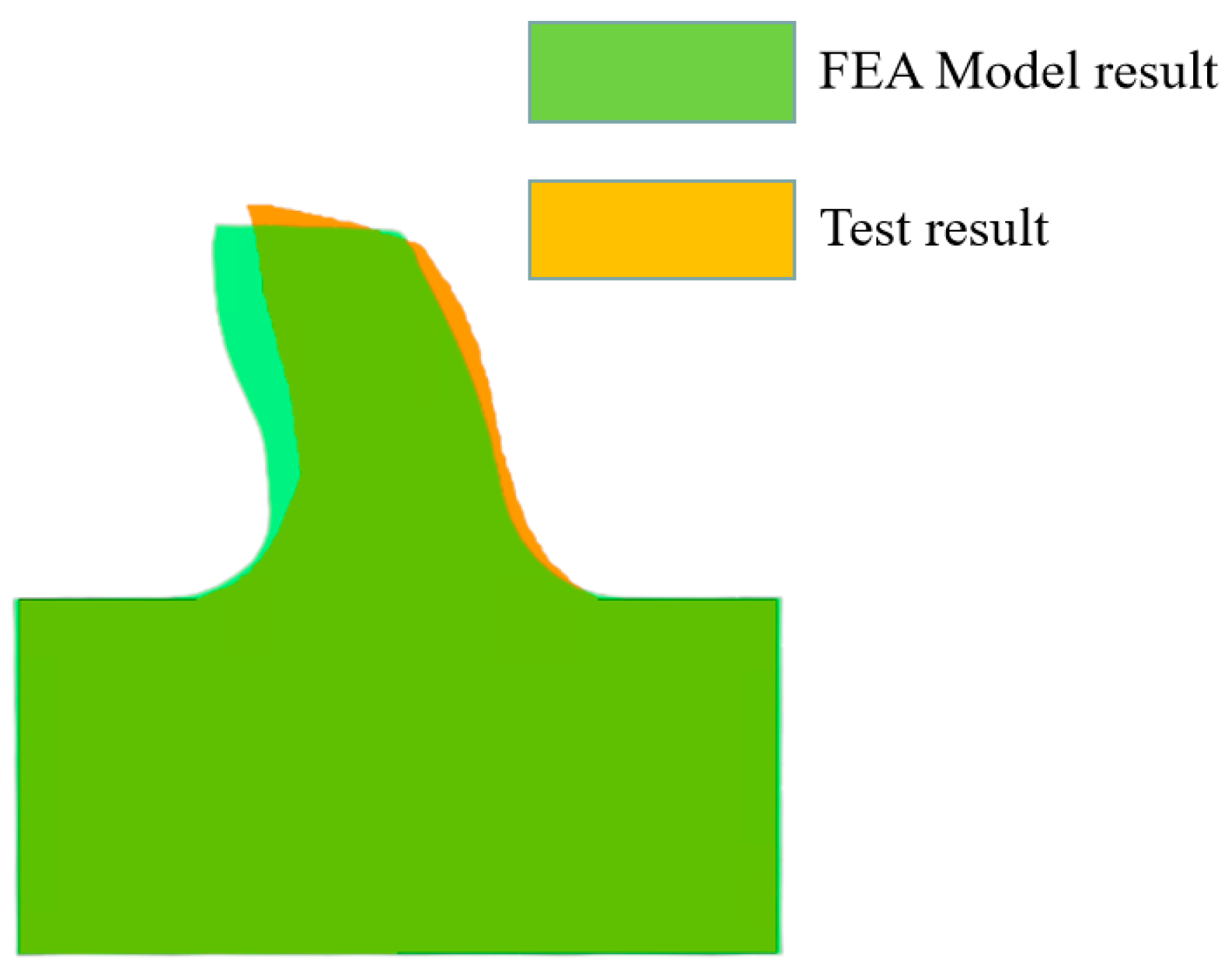
Coupled finite element analysis (FEA) for structural deformation and computational fluid dynamics (CFD) for flow analysis were core to this investigation. The FEA model simulating rub-impact induced deformation was rigorously validated against experimental measurements, demonstrating high accuracy (e.g., a 5.1% discrepancy in post-impact tooth height for mild interference conditions) and confirming its ability to capture the dominant plastic yielding behavior observed in thermoplastic materials.
(3)
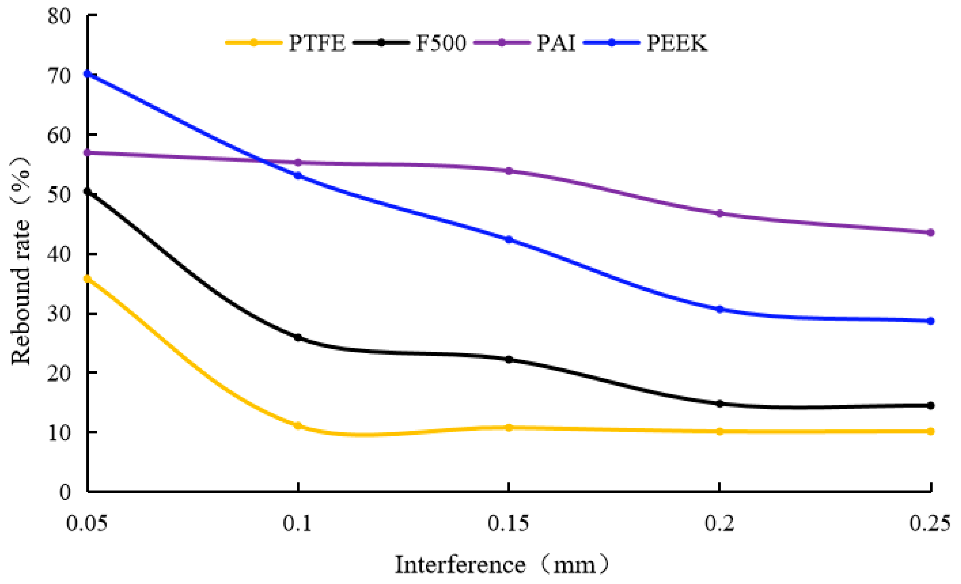
The deformation mechanisms revealed that interference level is the primary operational parameter governing tooth deformation, causing significant reductions in tooth height (1.3–12%) and increases in tip width (2–60%) within the tested range (0.05–0.25 mm). In contrast, impact frequency variations (0.83–13.33 Hz) showed only a negligible impact on final tooth height (<3% change). A critical finding is the superior performance of high-strength thermoplastics like PAI and PEEK compared to conventional plastics (PTFE and F500). PAI and PEEK exhibited significantly higher elastic rebound ratios (up to 57% and 70.3%, respectively) and less permanent deformation, resulting in substantially smaller post-impact clearances (4.8–18.3% smaller) under identical conditions. This underscores their inherent resilience under rub-impact.
(4)
Subsequent CFD simulations, utilizing the deformed geometries from FEA, elucidated the leakage dynamics. Leakage rates were predominantly correlated with interference, causing a substantial increase compared to the original state; at 0.25 mm interference (reverse flow), increases ranged from 151% (PAI) to 217% (PTFE), highlighting material-dependent performance degradation. Meanwhile, tooth orientation modulated leakage by 0.5–3% through the vena contracta effect. Furthermore, the relative orientation of the deformed tooth profile to the gas inflow direction was found to modulate leakage (by 20–40%) primarily through its influence on the vena contracta effect. The ‘reverse flow’ configuration, where gas flow opposed the tooth bending, enhanced streamline contraction and reduced effective clearance.
(5)
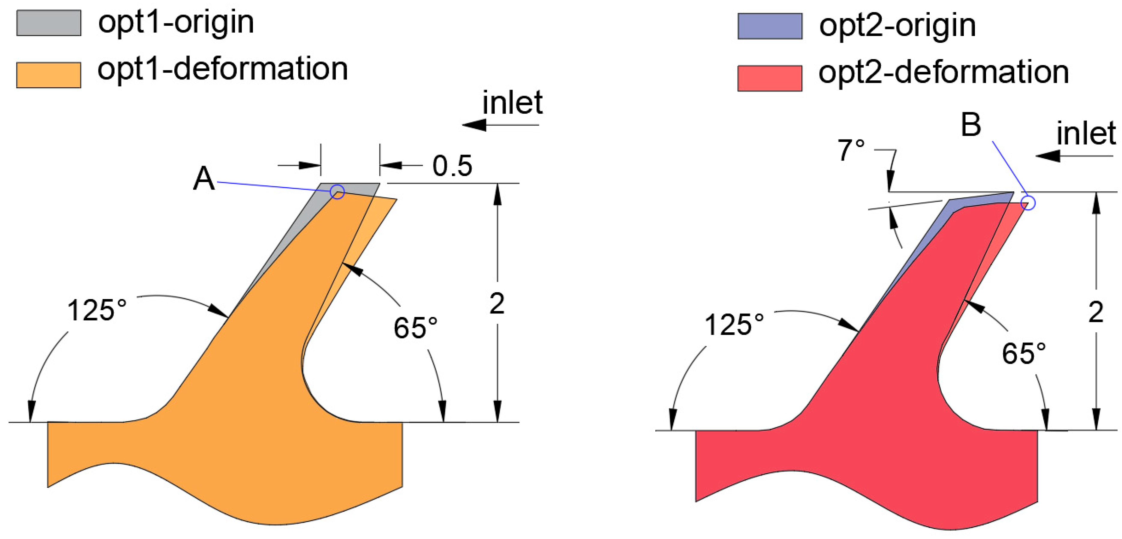
Leveraging these comprehensive insights into deformation and leakage mechanisms, two optimized inclined-tooth geometries (Opt1 and Opt2) based on the superior PAI material were designed. CFD analysis predicted significant leakage reductions for these designs after rub-impact with Opt1 achieving a 28.2% reduction and Opt2 achieving a 28.1% reduction compared to the original geometry. While Opt2 exhibited a slightly lower rebound ratio than Opt1 due to differences in localized contact mechanics influenced by its angled tip, its final post-impact geometry proved equally effective in minimizing leakage, validating the potential of tailored geometric optimization based on the understanding of deformation effects.
Limitations and Future Work: It is important to note that the current FEA framework primarily focuses on deformation under low-to-moderate interference and does not fully incorporate complex severe wear behavior. Future studies will integrate transient wear models and conduct high-temperature experiments to improve predictive accuracy under more extreme operational conditions. Additionally, exploring multi-physics coupling effects, such as thermal–structural–fluid interactions, is a crucial next step for advancing high-performance seal design for harsh environments

Author Contributions

Conceptualization, F.M., Z.Y. and Y.L.; Data curation, F.M.; Formal analysis, Z.Y. and Y.L.; Funding acquisition, F.M. and Z.Y.; Investigation, Y.L.; Methodology, F.M. and S.S.; Project administration, F.M. and P.S.; Resources, Y.L. and P.S.; Software, F.M. and S.S.; Supervision, S.S. and P.S.; Validation, S.S. and Y.L.; Visualization, Z.Y.; Writing—original draft, F.M. and Z.Y.; Writing—review and editing, S.S. and P.S. All authors have read and agreed to the published version of the manuscript.

Funding

This research was funded by the Ministry of Civil Affairs rehabilitation field key laboratory and engineering technology research center operating expenses project (Number 102118170090010009004) and the Young Backbone Teacher Support Plan of the Beijing Information Science and &Technology University (Number 5112411115).

Data Availability Statement

Data are contained within the article.

Conflicts of Interest

The authors declare no conflicts of interest.

References

  1. Lin, Z.; Wang, X.; Yuan, X.; Shibukawa, N.; Noguchi, T. Investigation and improvement of the staggered labyrinth seal. Chin. J. Mech. Eng. 2015, 28, 402–408. [Google Scholar] [CrossRef]
  2. Rhode, D.L.; Adams, R.G. Rub-groove width and depth effects on flow predictions for straight-through labyrinth seals. J. Tribol. 2004, 126, 781–787. [Google Scholar] [CrossRef]
  3. Whalen, J.K.; Dugas, J.R., Jr. Upgrading Centrifugal Compressors with Polymer Seals in an Ethylene Plant—A Case History. In Proceedings of the Twenty-Ninth Turbo-machinery Symposium, Turbomachinery Laboratory, George R. Brown Convention Center, Houston, TX, USA, 18–21 September 2000; Texas A&M University: College Station, TX, USA, 2000; pp. 31–37. [Google Scholar]
  4. Kirk, G.; Gao, R. Influence of preswirl on rotor dynamic characteristics of labyrinth seals. Tribol. Trans. 2012, 55, 357–364. [Google Scholar] [CrossRef]
  5. Vannini, G.; Bertoneri, M.; Nielsen, K.K.; Iudiciani, P.; Stronach, R. Experimental results and computational fluid dynamics simulations of labyrinth and pocket damper seals for wet gas compression. J. Eng. Gas Turbines Power 2016, 138, 052501. [Google Scholar] [CrossRef]
  6. Corral, R.; Greco, M.; Vega, A. Effective clearance and differential gapping impact on seal flutter modeling and validation. J. Turbomach. 2022, 144, 071010. [Google Scholar] [CrossRef]
  7. Gu, Q.L.; Zhang, W.F.; Chen, L.Q.; Ma, K.; Li, C.; Yang, J.A. Study on the Critical Stable State of the Labyrinth Seal. J. Mech. Eng. 2020, 56, 144–151. [Google Scholar]
  8. Cao, H.C.; Xu, Y.R.; Sun, N.N.; Lu, J.; Zhu, G.X.; Li, Y.J. Analysis and Experimental Research for Leaking Behavior of Labyrinth Seals under Gas-liquid Two-phase Conditions. China Mech. Eng. 2023, 34, 623–629. [Google Scholar]
  9. Yang, Y.; Mi, Z.; Zhang, W.; Chang, J.; Liu, Y.; Zhong, B.; Yang, W. Experimental Study on the Effect of Rubbing Mode on Radial Crack Initiation in Labyrinth Seal Fins of Shrouded Turbine Blade. Aerospace 2022, 9, 441. [Google Scholar] [CrossRef]
  10. Pychynski, T.; Hofler, C.; Bauer, H.J. Experimental study on the friction contact between a labyrinth seal fin and a honeycomb stator. J. Eng. Gas Turbines Power 2016, 138, 062501. [Google Scholar] [CrossRef]
  11. Subramanian, S.; Sekhar, A.S.; Prasad, B. Influence of combined radial location and growth on the leakage performance of a rotating labyrinth gas turbine seal. J. Mech. Sci. Technol. 2015, 29, 2535–2545. [Google Scholar] [CrossRef]
  12. Katcher, K.M.; Revak, T.; Rimpel, A.; Ratay, J.; Brun, K. Abradable Seal Test Rig for Quantifying Abradable Material Performance During Labyrinth Seal Rubs in Centrifugal Compressors: Design and Test Results. In Proceedings of the ASME Turbo Expo 2022: Turbomachinery Technical Conference and Exposition, Rotterdam, The Netherlands, 13–17 June 2022; p. V007T19A005. [Google Scholar]
  13. Yang, S.; Tan, B.; Deng, X. Numerical and Experimental Investigation of the Sealing Effect of a Specific Labyrinth Seal Structure. Math. Probl. Eng. 2019, 2019, 9851314. [Google Scholar] [CrossRef]
  14. Whalen, J.K.; Alvarez, E.; Palliser, L.P. Thermoplastic labyrinth seals for centrifugal compressors. In Proceedings of the Thirty-Third Turbomachinery Symposium, Houston, TX, USA, 20–23 September 2004. [Google Scholar]
  15. Rhode, D.L.; Adams, R.G. Computed Effect of Rub-Groove Size on Stepped Labyrinth Seal Performance. In Proceedings of the ASME Turbo Expo 2000: Power for Land, Sea, and Air. Volume 3: Heat Transfer; Electric Power; Industrial and Cogeneration, Munich, Germany, 8–11 May 2000; p. V003T01A093. [Google Scholar]
  16. Dogu, Y.; Sertcakan, M.C.; Bahar, A.S.; Pişkin, A.; Arıcan, E.; Kocagül, M. Computational fluid dynamics investigation of labyrinth seal leakage performance depending on mushroom-shaped tooth wear. J. Eng. Gas Turbines Power 2016, 138, 032503. [Google Scholar] [CrossRef]
  17. Dogu, Y.; Sertcakan, M.C.; Gezer, K.; Kocagül, M.; Arıcan, E.; Ozmusul, M.S. Labyrinth Seal Leakage Degradation Due to Various Types of Wear. J. Eng. Gas Turbines Power 2017, 139, 062504. [Google Scholar] [CrossRef]
  18. Yan, X.; Wang, H.; He, K. Investigations into rubbing wear behavior of honeycomb land against labyrinth fin with periodic-cell model. Proceedings of the Institution of Mechanical Engineers. Part A J. Power Energy 2024, 238, 1399–1413. [Google Scholar] [CrossRef]
  19. Jiang, J.; Yang, Y.; Huang, W.; Li, Y. Numerical and experimental investigation on uniformity of pressure loads in labyrinth seal. Adv. Mech. Eng. 2017, 9, 1687814017728455. [Google Scholar] [CrossRef]
  20. Dai, X.; Yan, X.; He, K.; Li, J.; Feng, Z. Numerical investigations of leakage performance degradations in labyrinth and flexible seals due to wear. J. Eng. Gas Turbines Power 2021, 143, 051003. [Google Scholar] [CrossRef]
  21. Xu, J. Effects of Operating Damage of Labyrinth Seal on Seal Leakage and Wheel Space Hot Gas Ingress; Texas A&M University: College Station, TX, USA, 2007. [Google Scholar]
  22. Dowson, P.; Walker, M.S.; Watson, A.P. Development of abradable and rub-tolerant seal materials for application in centrifugal compressors and steam turbines. Seal. Technol. 2004, 2004, 5–10. [Google Scholar] [CrossRef]
  23. Zhang, M.; Childs, D.W. Effects of increased tooth clearance on the performance of a labyrinth seal with oil-rich bubbly laminar flow. J. Eng. Gas Turbines Power 2021, 143, 111007. [Google Scholar] [CrossRef]
  24. Xiang, Z.; Ying, H.J.; Xiu, Q.Q.; Zhi, Q.Z.; Guang, H.H.; Kai, H. Inlet preswirl dependence research on three different labyrinth seals. Tribol. Int. 2024, 176, 107929. [Google Scholar]
  25. Huang, J.Q.; Cao, X.Q.; Chen, W.B.; Guo, X.J.; Li, M.; Wang, W.J.; Dong, S.J.; Liu, L.; Chen, M.Z. A comprehensive review of thermally sprayed abradable sealing coatings: Focusing on abradability. Chin. J. Aeronaut. 2024, 37, 1–25. [Google Scholar] [CrossRef]
  26. Zhang, X.; Jiao, Y.H.; Du, H.Z.; Huo, G.H.; Xu, Y.Y.; Che, R. Transient investigations of teeth on rotor and teeth on stator modified labyrinth seals. Tribol. Int. 2024, 192, 109296. [Google Scholar] [CrossRef]
  27. Zhang, B.; Marshall, M.; Lewis, R. Investigating Al-Si base abradable material removal mechanism with axial movement in labyrinth seal system. Wear 2022, 510, 204496. [Google Scholar] [CrossRef]
  28. Yan, X.; Dai, X.; He, K. Experimental Study on Rubbing Wear Characteristics of Labyrinth Seal With Trapezoidal Fins. J. Tribol. 2022, 144, 032301. [Google Scholar] [CrossRef]
  29. Sun, W.W.; Liu, Y.; Li, Y.J.; Jiang, J. Analysis and experimental verification on the leakage of labyrinth seals under multiple factors. J. Tsinghua Univ. (Sci. Technol.) 2024, 64, 1414–1423. [Google Scholar]
  30. Liu, Y.; Huang, M.; Li, Y.J.; An, Q.; Jiang, J. Research on Leakage Characteristics of Thermoplastic Labyrinth Seals on High Pressure Differential. J. Mech. Eng. 2024, 60, 194–204. [Google Scholar]
Figure 1. Trapezoidal seal structure.
Lubricants 13 00250 g001
Figure 2. Rub-impact experimental system.
Lubricants 13 00250 g002
Figure 3. Key components of the system.
Lubricants 13 00250 g003
Figure 4. Shaft support system. (a) Rub-impact test bench. (b) Partial diagram of shaft support system.
Lubricants 13 00250 g004
Figure 5. Leakage experimental system.
Lubricants 13 00250 g005
Figure 6. FEA model and boundary condition.
Lubricants 13 00250 g006
Figure 7. Mesh independence verification (FEA model).
Lubricants 13 00250 g007
Figure 8. Schematic diagram of the mesh generation.
Lubricants 13 00250 g008
Figure 9. Mesh independence verification (CFD model).
Lubricants 13 00250 g009
Figure 10. CFD model (PTFE; interference = 0.25 mm; HZ = 3.33).
Lubricants 13 00250 g010
Figure 11. Comparison between simulation and test (FEA model).
Lubricants 13 00250 g011
Figure 12. Comparison between simulation and test (CFD model).
Lubricants 13 00250 g012
Figure 13. Process of rub-impact experiment. (a) Before rub-impact; (b) at the beginning of rub-impact; (c) rub-impact to maximum interference.
Lubricants 13 00250 g013
Figure 14. Shape of rub-impact sealing teeth.
Lubricants 13 00250 g014
Figure 15. Von Mises stress distribution.
Lubricants 13 00250 g015
Figure 16. Deformation distribution.
Lubricants 13 00250 g016
Figure 17. Leakage vs. interference for different materials.
Lubricants 13 00250 g017
Figure 18. Streamline contour at the first-stage sealing clearance of F500 material under rub-impact (interference: 0.25 mm).
Lubricants 13 00250 g018
Figure 19. Deformation patterns at different impact frequencies. (a) F500 deformation results; (b) PEEK deformation results.
Lubricants 13 00250 g019
Figure 20. Deformation patterns at different interference (HZ = 3.33). (a) F500 deformation results; (b) PTFE deformation results; (c) PAI deformation results; (d) PEEK deformation results.
Lubricants 13 00250 g020
Figure 21. Comparison of deformation results of different materials.
Lubricants 13 00250 g021
Figure 22. Rebound ratio vs. interference for different materials.
Lubricants 13 00250 g022
Figure 23. Tooth tip width vs. Interference for Different Materials.
Lubricants 13 00250 g023
Figure 24. Optimization design of thermoplastic labyrinth seal teeth.
Lubricants 13 00250 g024
Figure 25. Mises stress contour.
Lubricants 13 00250 g025
Figure 26. Leakage rate comparison of optimized seal structures under rub-impact.
Lubricants 13 00250 g026
Figure 27. Velocity contour. (a) Opt1; (b) Opt2.
Lubricants 13 00250 g027
Table 1. Material properties.
Properties MaterialsPTFEF500PAIPEEK
Density (kg/m3)2200232014101310
Elastic modulus (MPa)1400120026513700
Poisson’s ratio0.460.360.360.36
Compressive yield strength (MPa)151234.4775
Table 2. CFD model settings.
ParametersSettings
Solution methodSteady
Turbulence modelk-ε turbulence model
Boundary conditionPressure inlet; pressure outlet
Solution methodsSIMPLEC
Residuals1 × 10−6
Disclaimer/Publisher’s Note: The statements, opinions and data contained in all publications are solely those of the individual author(s) and contributor(s) and not of MDPI and/or the editor(s). MDPI and/or the editor(s) disclaim responsibility for any injury to people or property resulting from any ideas, methods, instructions or products referred to in the content.

