Abstract
Currently, there is limited experimental research on the stability of journal bearing-rotor systems under base motion, and the influence of rocking motion on the stability of such systems remains unclear. This study develops an experimental test rig for a journal bearing-rotor system and employs a six-degrees-of-freedom shaking table to apply complex alternating loads, with the aim of investigating the effects of rocking amplitude and frequency on the vibration characteristics of the shaft system. The experimental results show that, under the excitation of base roll and pitch motions, the critical speed of the sliding bearing-rotor system remains nearly unchanged, while the resonance amplitude increases significantly, and the instability speed occurs earlier. In addition, base rocking motion not only induces periodic and uniform changes in the vibration amplitude of the shaft system but also demonstrates a strong positive correlation between the amplitude of system vibration and the amplitude of base rocking.
1. Introduction
The dynamic characteristics of rotor-bearing systems are crucial for many applications in mechanical engineering, particularly in high-speed rotating machinery and complex operating conditions such as surface ships, aircraft, and centrifugal pumps. Recent research has highlighted the significant impact of base motion (e.g., ship pitching, rolling, and heaving) and external excitations (e.g., earthquakes, wind loads, and wave forces) on the dynamic behavior of rotor-bearing systems. Specifically, ships experience random heave and rocking motions due to wave impacts, which increase the capsizing moment and affect ship stability, potentially leading to capsizing [1,2]. Therefore, it is essential to consider the effects of base rocking on the vibration characteristics of journal bearing-rotor systems.
In the early stages, research primarily focused on the vibration characteristics of journal bearing-rotor systems under conditions where there was no base rocking. For instance, J.W. Lund [3] and J. Glienicke [4] proposed using the linear stiffness and damping coefficients of journal bearings to describe their dynamic characteristics. Based on these eight coefficients, they developed a linear theory to predict oil film instability in journal bearing-rotor systems. Lin [5] developed a 4-degrees-of-freedom dynamic model using the assumed modes method for a dual-disc rotor-bearing system, considering the nonlinear vibration characteristics and stability under multifrequency excitation. The results indicate that variations in system parameters alter the relative positions of resonance peaks, thereby exerting more complex influences on the nonlinear response. Additionally, Xue [6] investigated the dynamic characteristics of accelerated rotors on SHSB. The results demonstrated that, as the target rotational speed increased, the shaft center orbit during acceleration exhibited progressively intricate complexity, accompanied by a prolonged stabilization time required for the bearing system. Furthermore, elevated unbalanced levels induced significant increases in both vibration amplitude and frequency during acceleration, thereby diminishing the stability of the rotor system. Zhongliang Xie et al. [7,8,9,10] investigated the impact mechanisms of bearing misalignment, radial clearance, and thermal effects on the performance of water-lubricated bearings (WLBs), providing theoretical support for the design of rotor systems with water-lubricated bearings in marine environments. Jon S. Larsen [11] utilized the finite element method to discretize the Reynolds equation and established a mathematical model that could accurately predict the nonlinear steady-state response of rigid rotors supported by gas film bearings. Jin [12] proposed a novel dynamic model for a double-disc cracked rotor-bearing system with an inner race defect. A quantitative dual-impulse model was employed to investigate the effects of the dual-impulse phenomenon caused by the inner race defect on the system’s stability and transient response.
As research has progressed, scholars have increasingly focused on the effects of base motion on rotor-bearing systems. Rui Wang et al. [13] developed a nonlinear rotor system model using the Lagrange method. Their study demonstrated that linearized models are inadequate for accurately representing the actual dynamic behavior of bearing-rotor systems, especially under complex operating conditions such as combined base motion and centrifugal forces. Zhanxing Liu [14] established a novel oil film force model considering base motion by combining the Lagrange principle with the finite element method. The results showed that the harmonic motion of the base significantly amplifies the rotor trajectory, particularly under the influence of inertial forces, leading to a substantial increase in the vibration amplitude of the rotor. MajidiRad et al. [15] developed a simple numerical model using the finite element method and compared the simulation results with experimental data to investigate the impact of base excitation on the deviation of the rotor from its normal operating state. Bo Zhang et al. [16] used a multidimensional harmonic balance method combined with an alternating frequency-domain approach to calculate the steady-state response of the rotor system. Their findings indicated that the time-varying parameters of base motion have a significant effect on the amplitude–frequency response of the lateral displacement of the rotor system. Jarroux et al. [17] studied the nonlinear dynamic characteristics of actively magnetically supported rotors under base motion using both experimental and numerical methods. Mzaki Dakel et al. [18,19] investigated the dynamic behavior of a rigid rotor subjected to base excitation and mass imbalance. Subsequently, they extended their study to examine the nonlinear dynamic behavior of a flexible rotor system under base motion. The results demonstrated that base rotation significantly alters the natural frequencies of the rotor. Additionally, at higher levels of sinusoidal base excitation, the system may enter an unstable state or exhibit complex nonlinear dynamic behavior.
Several scholars have conducted research on rotor-bearing systems under specific application scenarios, providing valuable insights into their dynamic behavior. Yongchao Han [20] developed a mathematical model based on short bearing theory in a non-inertial reference frame, incorporating heave motion. Using numerical integration methods, Han analyzed the dynamic characteristics of the system. The results showed that heave motion has a significant impact on the dynamics of the rotor system. Wenzhuo Zhang [21] considered the coupled pitch and heave motions of ships, as well as the nonlinear oil film moments caused by rotor tilt. His findings indicated that under high-speed conditions, the amplitude of the rotor system increases dramatically, potentially leading to contact between the rotor and the inner wall of the bearing.
Zhao et al. [22] investigated the steady-state response of a coupled airbag–raft rotor-bearing system, analyzing the effects of system spectra, orbits, and parameters. Their results demonstrated that at low speeds, the system exhibits single-periodic motion; as speed increases, the motion gradually transitions to quasi-periodic and chaotic states. Zheming Tong et al. [23] proposed a new method for modeling the dynamics of gear systems, considering the influence of ship heave motion. They analyzed the impact of key wave and navigation parameters on gear dynamics, providing a comprehensive understanding of the system’s behavior under marine conditions. Fusheng Lin [24] established a mathematical model for an unbalanced rotor system in maneuvering flight, showing that the flight state of the aircraft significantly affects the unbalance response of the rotor. Gaganis et al. [25] studied the nonlinear characteristics of rotor systems under different support conditions, considering seismic loads. Their research highlighted the complex interactions between seismic forces and rotor dynamics. Zhang Guanghui et al. [26] developed a nonlinear model for rotor-bearing systems that incorporates coupled base motion and nonlinear oil film forces. Their study focused on the impact of unbalanced mass on the system’s nonlinear dynamics. The results indicated that the pitch and roll motions of ships introduce additional excitation vectors and stiffness matrices, altering the nonlinear oil film forces and, thus, affecting the system’s dynamic behavior.
In previous studies, researchers have primarily focused on theoretical analyses of bearing-rotor systems under base motion, such as establishing theoretical models to simulate roll motion, pitch motion, and coupled pitch–roll–heave motions through numerical simulations. However, the experimental validation and empirical exploration of rotor stability evolution remain significantly underdeveloped. To address this research gap, the present study designs and constructs a six-degrees-of-freedom (6-DOF) coupled test rig for a journal bearing-rotor system, which inputs variable rocking periods and amplitudes to replicate typical maritime conditions encountered during ship navigation. This experimental framework not only fills the gap of experimental research to study the stability of the system under complex rocking loads but also reveals the influence laws of base pitch and roll motions on the critical speed, instability threshold and vibration response of the rotor system through the measured data. These findings provide an important engineering reference for the stability design of ship propulsion systems.
2. Test Summary
2.1. Base Motion Device
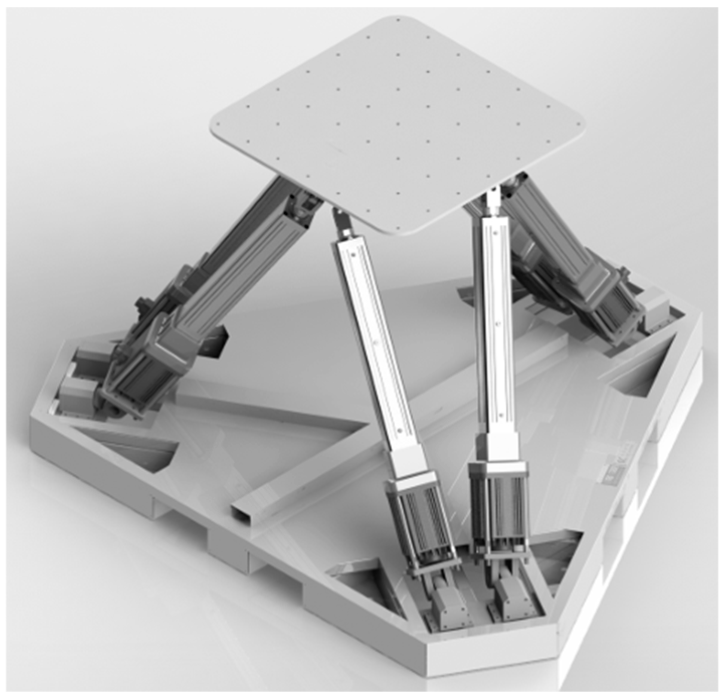
To address the stochastic motions experienced by ships during navigation, this study simplifies these motions into sinusoidal forms. A six-degrees-of-freedom (6-DOF) platform is employed to simulate the roll and pitch motions encountered during ship navigation. Figure 1 illustrates the 6-DOF platform utilized in this research. The parameters of the six-degrees-of-freedom platform are shown in Table 1.

Figure 1.
Six-degrees-of-freedom platform.

Table 1.
Six-degrees-of-freedom platform technology parameters.
2.2. Test Conditions
This study consisted of two main cases: the base roll motion and pitch motion. For the roll motion, it is divided into four groups, each corresponding to different roll periods (3 s, 6 s, 9 s, 12 s). For each period, there are identical roll amplitudes (4°, 8°, 12°, 16°, 20°). For the pitch motion, it is similarly divided into four groups, each corresponding to different pitch periods (3 s, 6 s, 8 s, 10 s). For each period, there are identical pitch amplitudes (2°, 4°, 6°, 8°, 10°). Table 2 presents the various experimental conditions.
Table 2.
Experimental parameters.
2.3. Test Rig
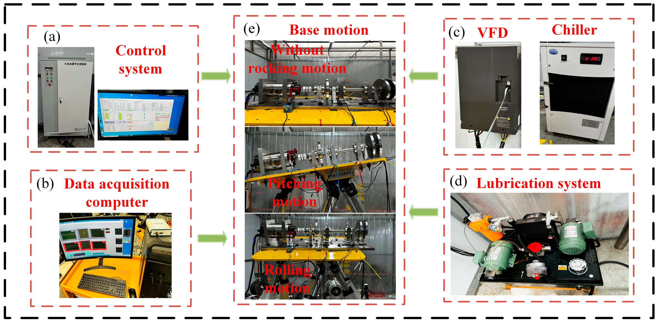
The journal bearing-rotor system test rig is shown in Figure 2, which mainly includes the power system, control system, lubrication system and acquisition system. The power system adopts a motor with a rated power of 37 kW and a maximum speed of 30,000 r/min. During the test, different parameters are inputted via the computer to realize the control of the rocking amplitude and rocking period of the six-degrees-of-freedom platform to achieve the base roll and pitch motion. The lubrication system is shown in Figure 2d, and the supply pressure is set to 0.1 MPa to ensure that the bearings are well lubricated during the experimental process, to reduce friction and to improve the reliability and repeatability of the test.
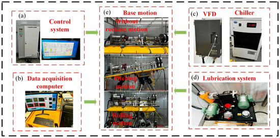
Figure 2.
Journal bearing-rotor system: (a) control system; (b) data acquisition computer; (c) vfd and chiller; (d) lubrication system; (e) base motion.
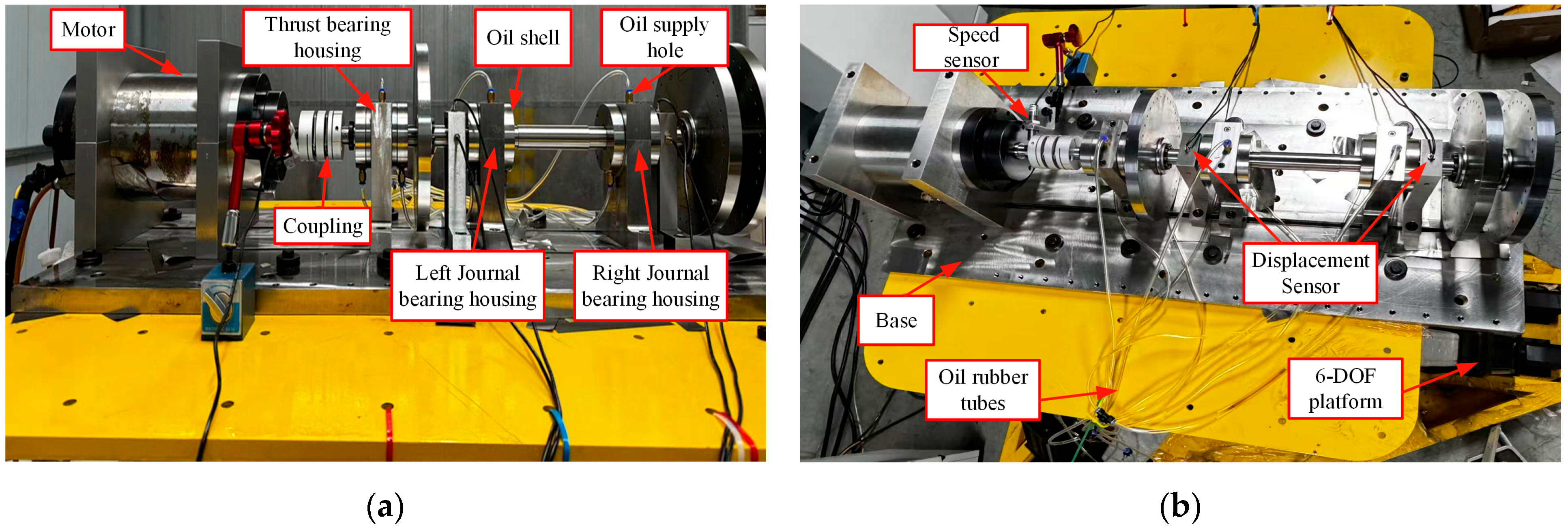
The main view of the test rig is shown in Figure 3a, and all components are installed and arranged on the six-degrees-of-freedom platform symmetrically. Two eddy current displacement sensors at 90° to each other were placed at the journal bearing support positions for monitoring the vibration characteristics of the rotor, and the support positions are named as the left bearing support and the right bearing support. The rotational speed sensor is arranged at the position of the motor spindle, and reflective tape is utilized for reflective measurement to obtain accurate rotational speed data.

Figure 3.
Test rig: (a) main view; (b) top view.
The journal bearing used in this experiment is shown in Figure 4. The parameters of the bearings supporting both sides of the rotor are identical, and the specific parameters are presented in Table 3.
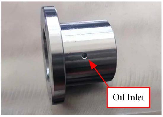
Figure 4.
Test bearing.
Table 3.
Parameters of journal bearing.
2.4. Test Procedure
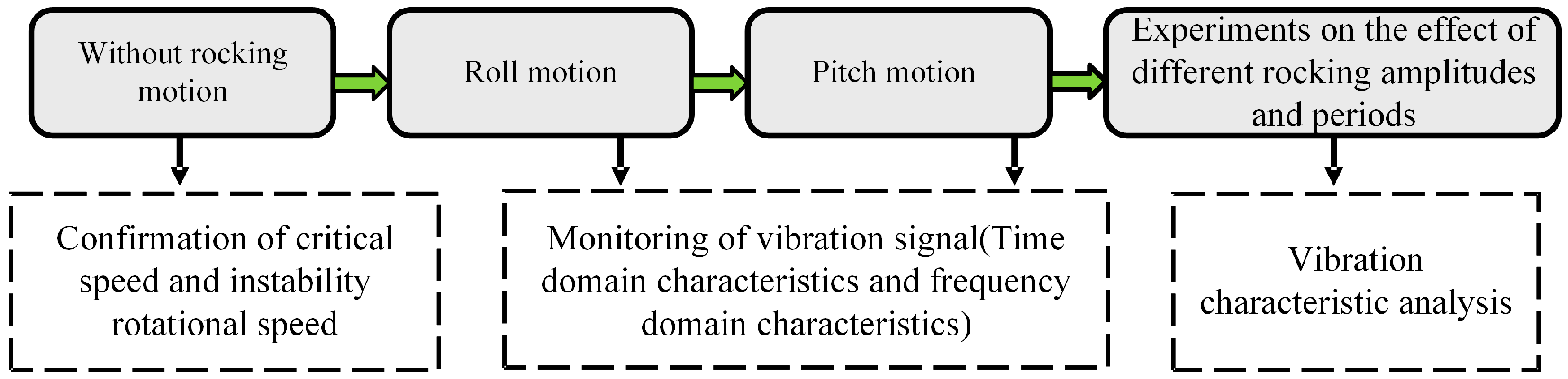
The testing process is as follows: The rotor dynamics experiment under non-rocking conditions was conducted to measure the critical and instability speeds using eddy current displacement sensors and optical tachometers. When the rotational speed reached 1500 r/min, the six-degrees-of-freedom platform was activated to perform roll and pitch tests, and the rocking frequency was monitored in real time. The vibration characteristics under non-rocking conditions were compared with those under roll and pitch conditions to investigate the effects of different rocking amplitudes and periods. Because of the larger load at the right bearing support of the system, the following section focuses on analyzing the vibration characteristics of the rotor at the right bearing position. The test flow chart is shown in Figure 5. All test results below are based on the rotor vibration response at the right bearing measurement point, unless otherwise stated.

Figure 5.
Flow chart.
3. Results and Discussion
3.1. Vibration Characterization of the System Without Rocking Motion
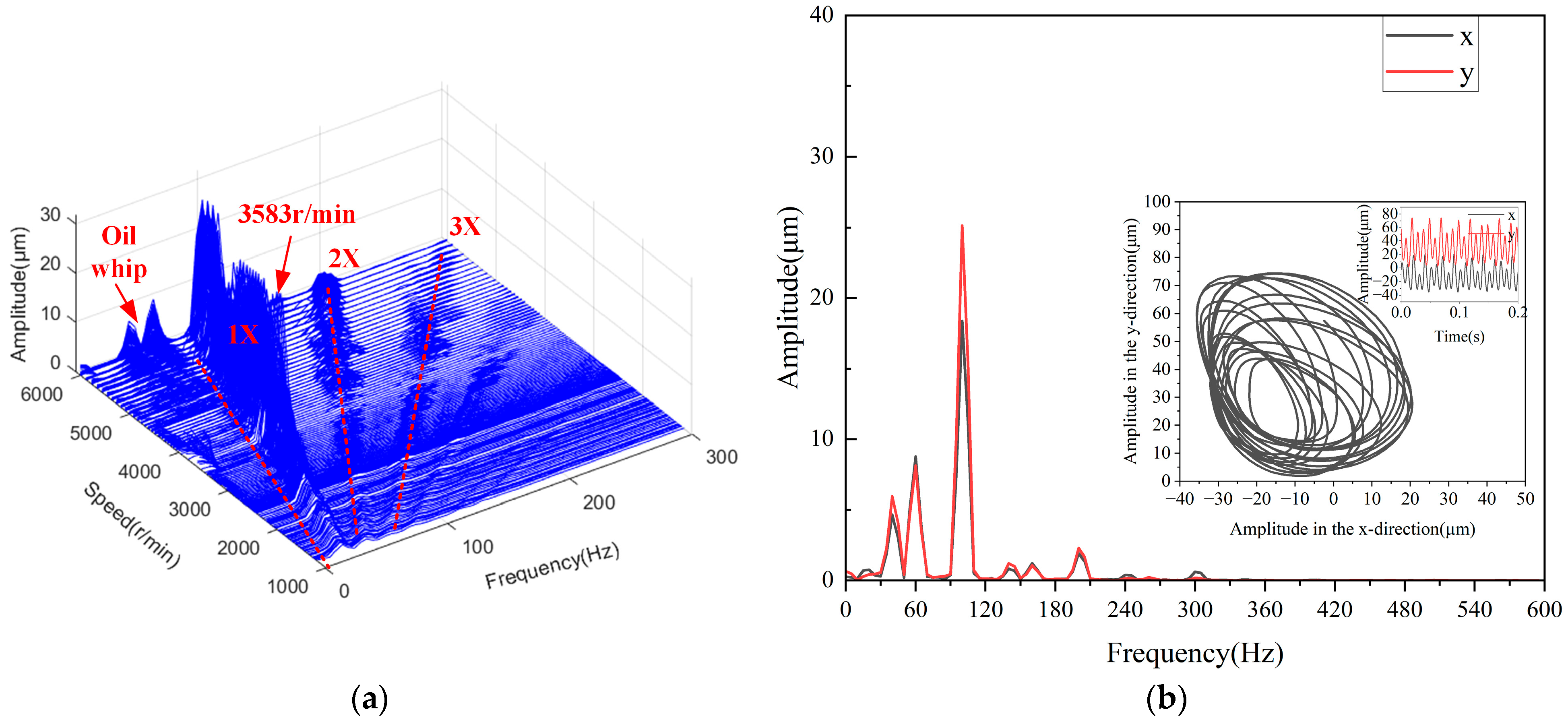
Figure 6a presents a waterfall plot of the rotor system in the y-direction under conditions without base rocking motion. From the figure, it can be observed that as the rotor speed increases from 1500 r/min to 6060 r/min, the vibration amplitude of the rotor system significantly increases after exceeding 3000 r/min, reaching its maximum at 3583 r/min, followed by a rapid decrease. This phenomenon indicates that the first-order critical speed of the rotor system is 3583 r/min.
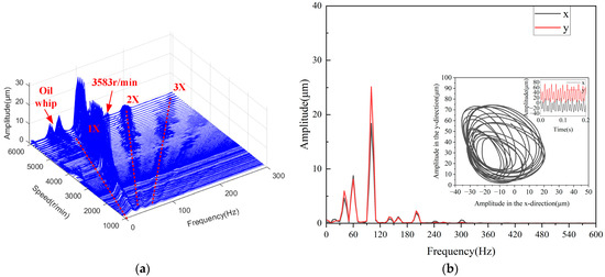
Figure 6.
System vibration response under base non-rocking conditions: (a) y-direction waterfall plot; (b) frequency spectrum.
When the speed is further increased to 6060 r/min (as shown in Figure 6b), the low-frequency vibration amplitude rapidly rises to 9 μm. Notably, in addition to the 0.4× fundamental frequency component, a 60 Hz low-frequency component also appears in the shaft system, which corresponds to the first-order critical speed of the rotor. Furthermore, the rotor’s orbit exhibits a divergent “petal-like” shape, indicating that oil whip has occurred, leading to the loss of system stability.
3.2. Influence of Pitch and Roll Motions on the Critical Speed of the System
In order to investigate the effect of the base rocking motion on the critical speed of the rotor system, the first-order critical speed of 3583 r/min without base rocking motion is taken as the baseline in this study. Under the condition of base rocking motion, the rotor speed is gradually increased from 3400 r/min to 4000 r/min, and the test data obtained under different rocking conditions are plotted as amplitude–frequency response curves.
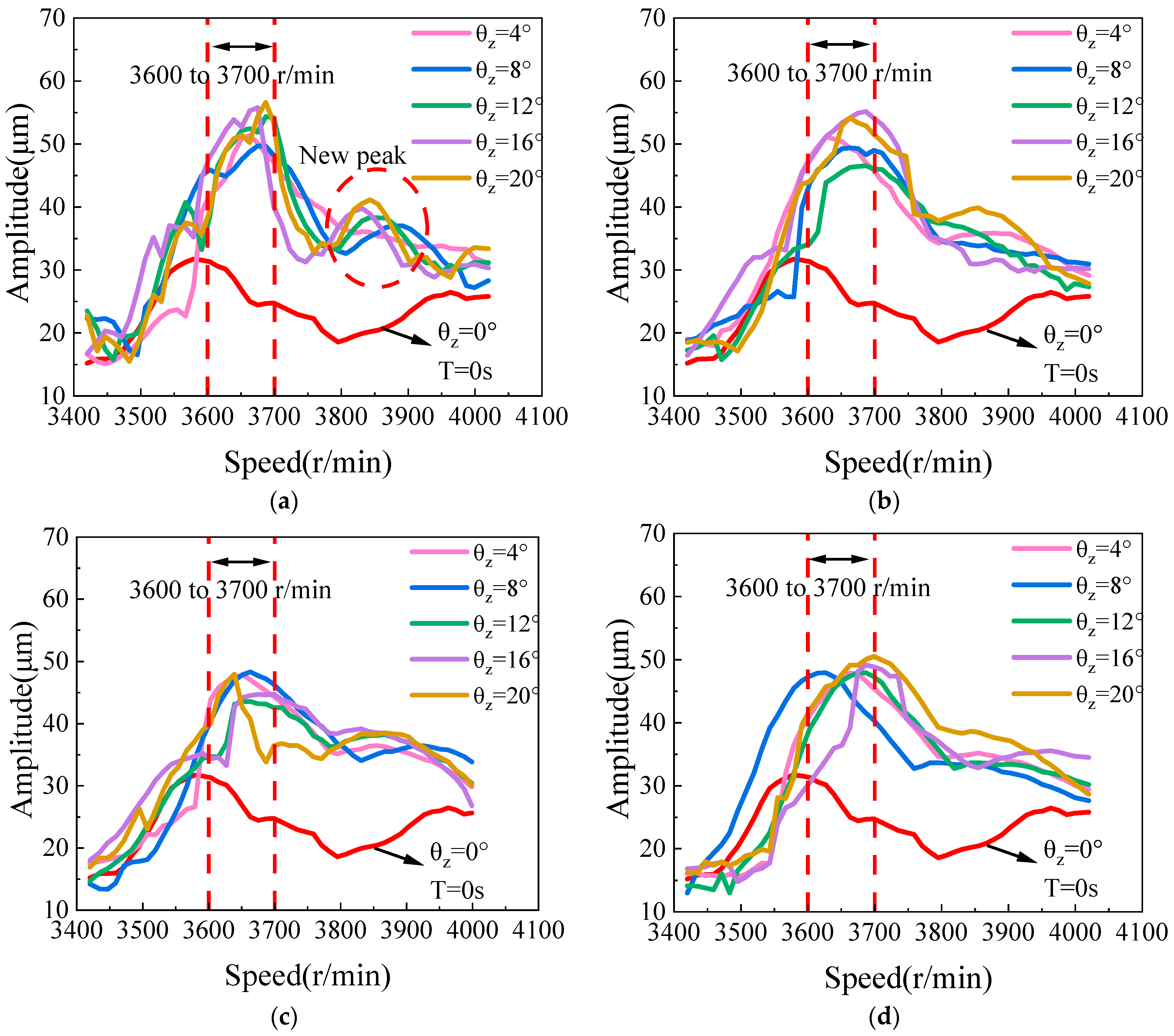
Figure 7 illustrates the trend of rotor vibration amplitude with rotational speed under different roll periods. As shown in Figure 7, when the roll amplitude increases from 4° to 20°, the critical rotational speeds under different roll test conditions are all between 3600 and 3700 r/min, and there is no obvious principle. The rotational speeds corresponding to the resonance peaks under the condition of a 3 s roll period are 3663 r/min, 3675 r/min, 3680 r/min, 3675 r/min, 3687 r/min, respectively; the rotational speeds corresponding to the resonance peaks under the condition of a 6 s roll period are 3627 r/min, 3660 r/min, 3675 r/min, 3680 r/min, 3655 r/min, respectively; the rotational speeds corresponding to the resonance peaks under the condition of a 9 s roll period are 3651 r/min, 3665 r/min, 3651 r/min, 3670 r/min, 3639 r/min; the rotational speeds corresponding to the resonance peaks under the condition of a 12 s rolling period were 3663 r/min, 3625 r/min, 3687 r/min, 3685 r/min, 3699 r/min, respectively.
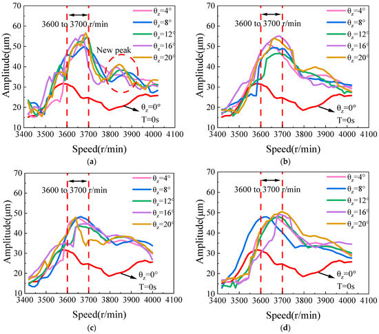
Figure 7.
System amplitude variation with rotational speed under roll motion: (a) 3 s; (b) 6 s; (c) 9 s; (d) 12 s.
Notably, after the primary resonance peak in the rotor system, a secondary peak with a significantly smaller amplitude is observed (see Figure 7a). Due to the base roll motion, the rocking load excitation no longer limits the journal motion to a small perturbation near the original static equilibrium position, which results in changes in bearing stiffness and damping. The first-order critical speed of the rotor system remains essentially unchanged, whereas the amplitude of the resonance peak increases significantly compared to the case without rocking motion.
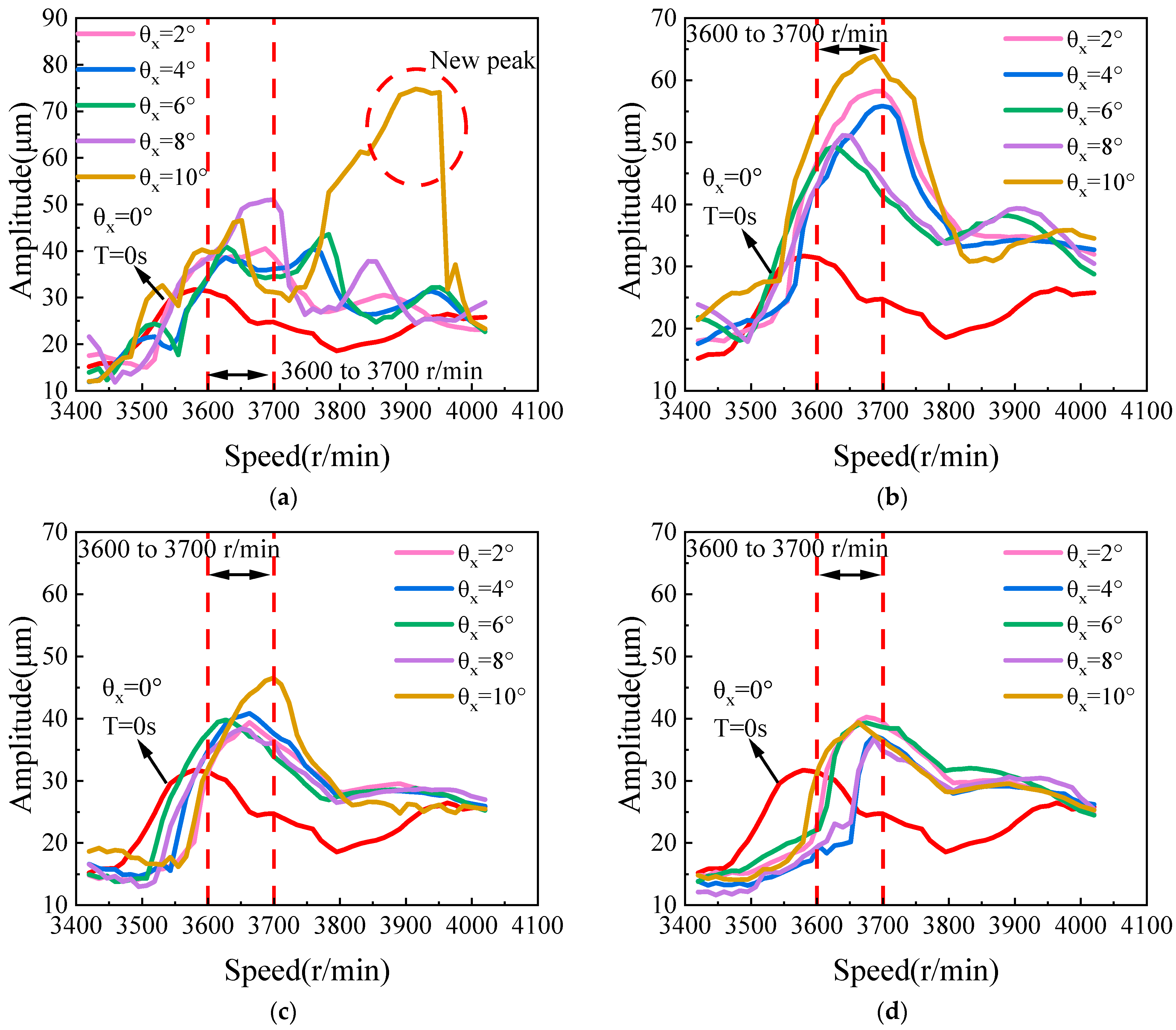
Figure 8 illustrates the trend of rotor vibration amplitude with rotational speed under different pitch periods. As shown in Figure 8, when the pitch amplitude increases from 2° to 10°, the critical rotational speeds under different pitch test conditions are all between 3600 and 3700 r/min, and there is no obvious principle. The rotational speeds corresponding to the resonance peaks under the condition of a 3 s pitch period are 3687 r/min, 3630 r/min, 3627 r/min, 3699 r/min, 3651 r/min, respectively; the rotational speeds corresponding to the resonance peaks under the condition of a 6 s pitch period are 3687 r/min, 3699 r/min, 3627 r/min, 3639 r/min, 3680 r/min, respectively; the rotational speeds corresponding to the resonance peaks under the condition of an 8 s pitch period are 3660 r/min, 3660 r/min, 3625 r/min, 3650 r/min, 3700 r/min; the rotational speeds corresponding to the resonance peaks under the condition of a 10 s pitch period are 3675 r/min, 3685 r/min, 3670 r/min, 3687 r/min, 3660 r/min, respectively.
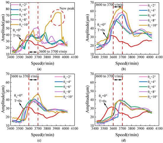
Figure 8.
System amplitude variation with rotational speed under pitch motion: (a) 3 s; (b) 6 s; (c) 8 s; (d) 10 s.
Notably, at a period of 3 s, the rotor experiences a secondary resonance peak after the first resonance peak (as shown in Figure 8a), with a significantly increased amplitude. This suggests that as the rocking period shortens, the base rocking frequency interacts with the rotor rotation frequency to trigger the secondary resonance.
3.3. Influence of Pitch and Roll Motions on System Vibration Amplitude
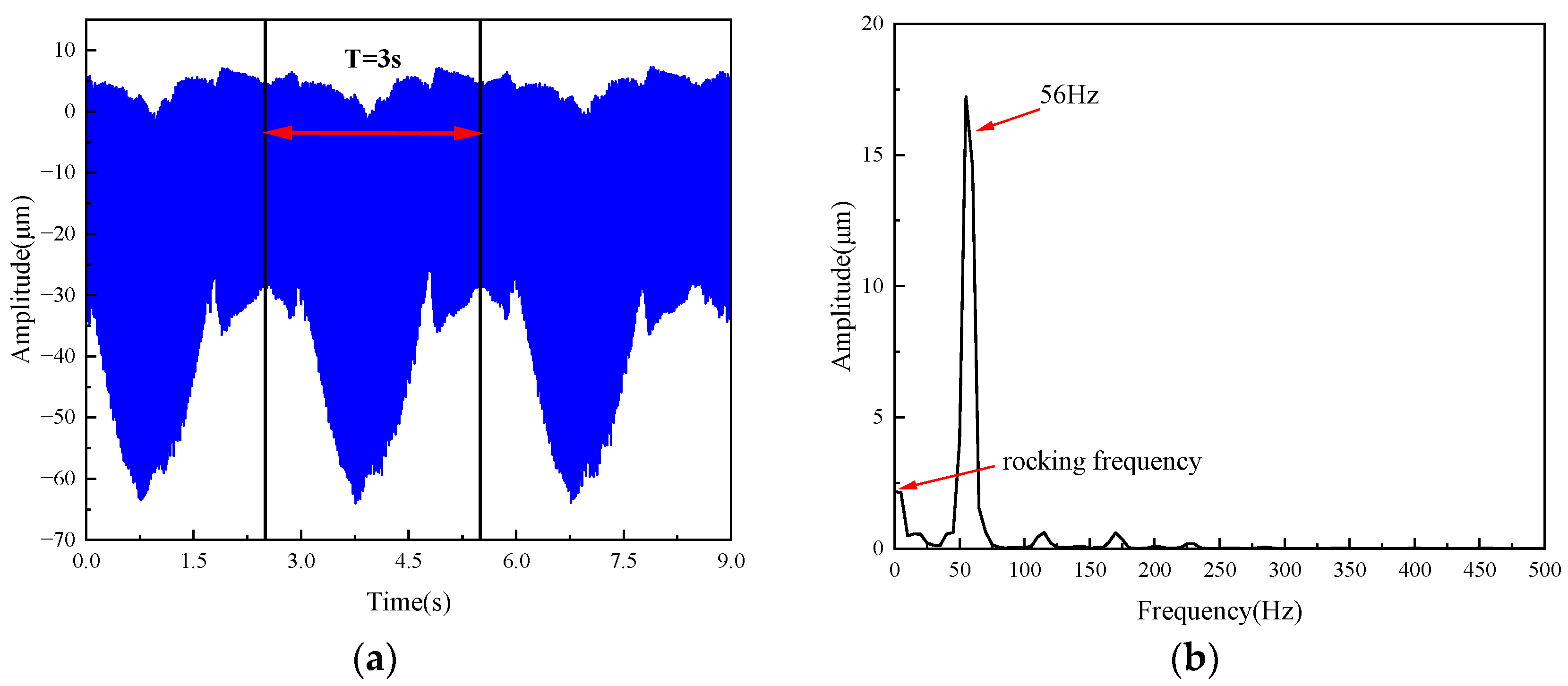
Figure 9 illustrates the vibration response characteristics of the rotor system under a rotational speed of 3400 r/min, a roll period of 3 s, and a roll amplitude of 20°. From Figure 9, time-domain fluctuations induced by roll excitation exhibit periodicity synchronized with the 3 s roll period (0.333 Hz). The frequency spectrum further reveals that, in addition to the fundamental vibration component (see Figure 9b), there exists a distinct frequency component at 0.333 Hz corresponding to the roll motion characteristics.
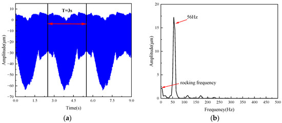
Figure 9.
The vibration response of the rotor during fundamental roll motion: (a) time-domain plot; (b) frequency spectrum.
To investigate the influence of rocking load excitation on the vibration characteristics of the rotor system, the rotor speed was set to 3400 r/min under conditions where the base under roll and pitch motions and the rotor speed approached the critical speed. The vibration data from five consecutive rocking periods were analyzed. Considering the potential non-stationary characteristics during the initial period, it was decided to exclude the data from the first cycle and extract and analyze only the fundamental frequency vibration data from the remaining four complete periods.
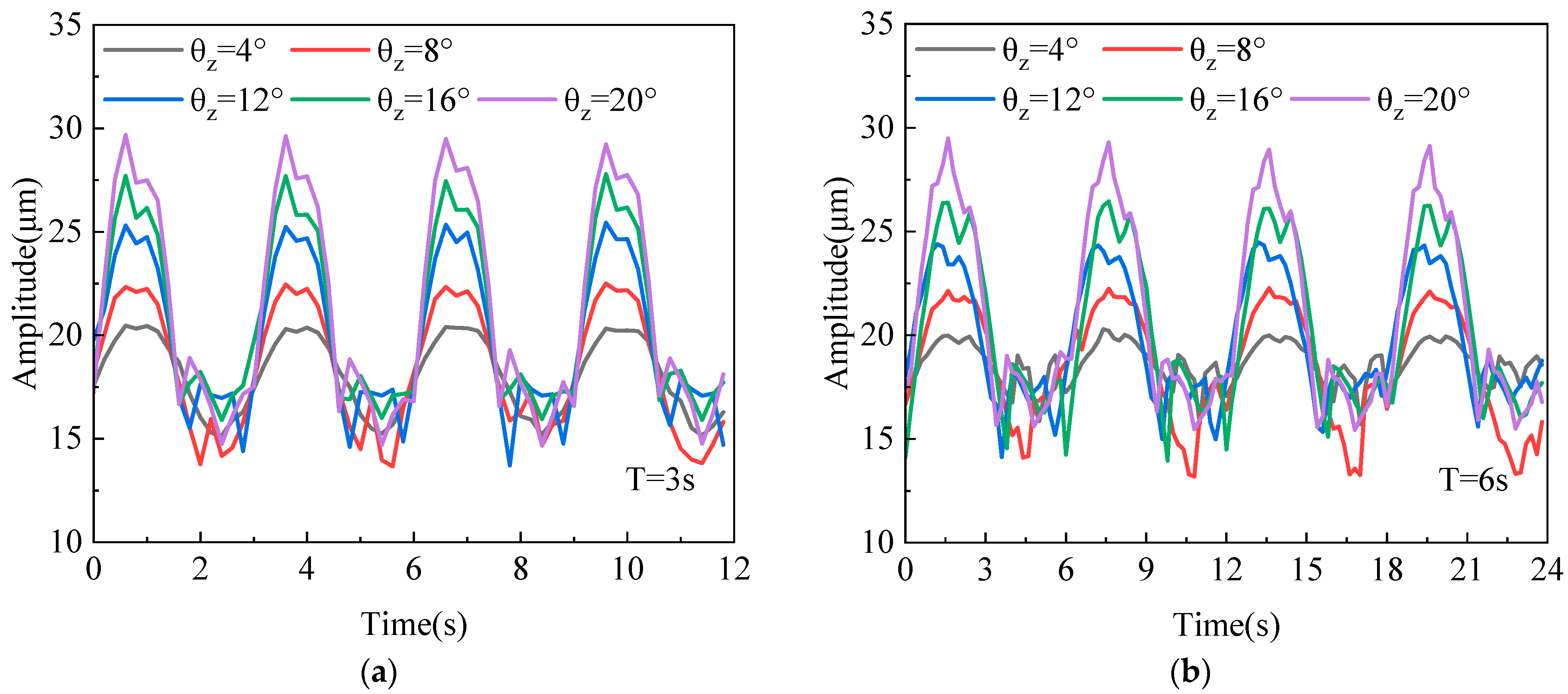
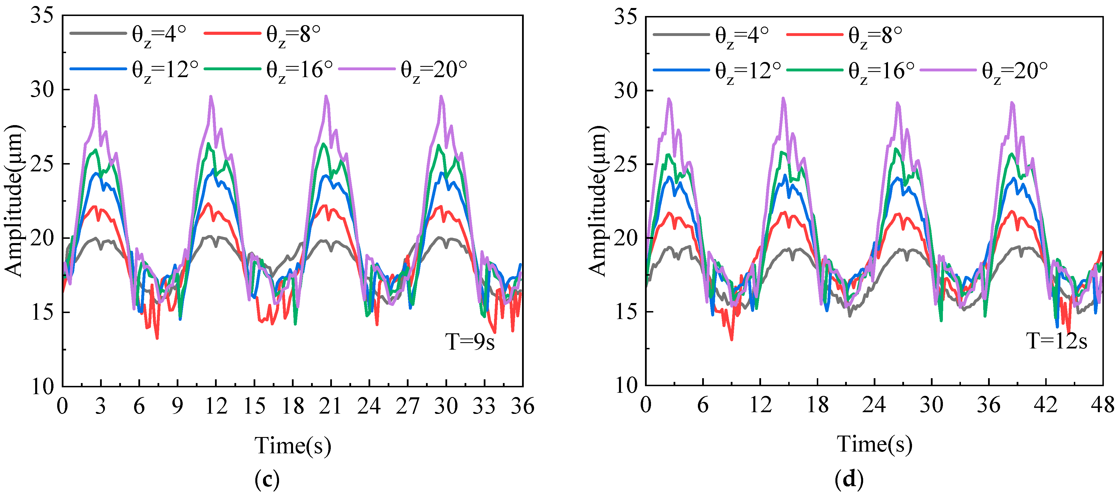
Figure 10 and Figure 11, respectively, present the variation trends of the fundamental frequency vibration amplitude in the y-direction of the rotor over time under different roll periods (3 s, 6 s, 9 s, 12 s) and pitch periods (3 s, 6 s, 8 s, 10 s) of the base. It can be observed from the figures that under the excitation of both roll and pitch motions, the fundamental frequency vibration amplitude of the rotor exhibits periodic variations that are synchronized with the base motion. Specifically, when the base undergoes roll motion with a fixed rocking amplitude, the variation trends of the fundamental frequency vibration amplitude under different roll periods are similar. In contrast, when the base undergoes pitch motion, the variation trend of the fundamental frequency vibration amplitude becomes more pronounced as the pitch frequency increases.
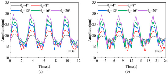
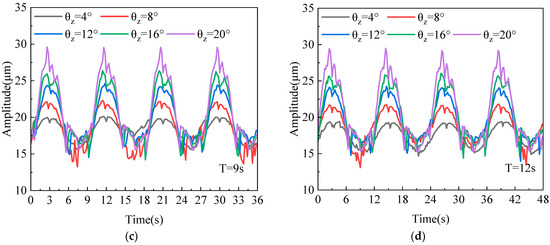
Figure 10.
Time-domain amplitude of fundamental vibration under roll motion: (a) 3 s; (b) 6 s; (c) 9 s; (d) 12 s.
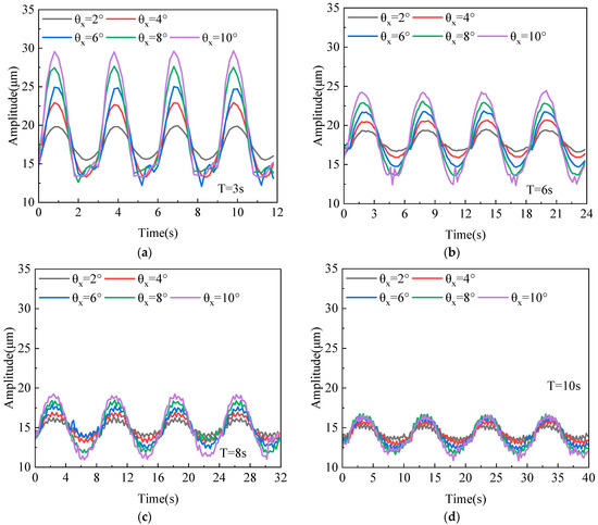
Figure 11.
Time-domain amplitude of fundamental vibration under pitch motion: (a) 3 s; (b) 6 s; (c) 8 s; (d) 10 s.
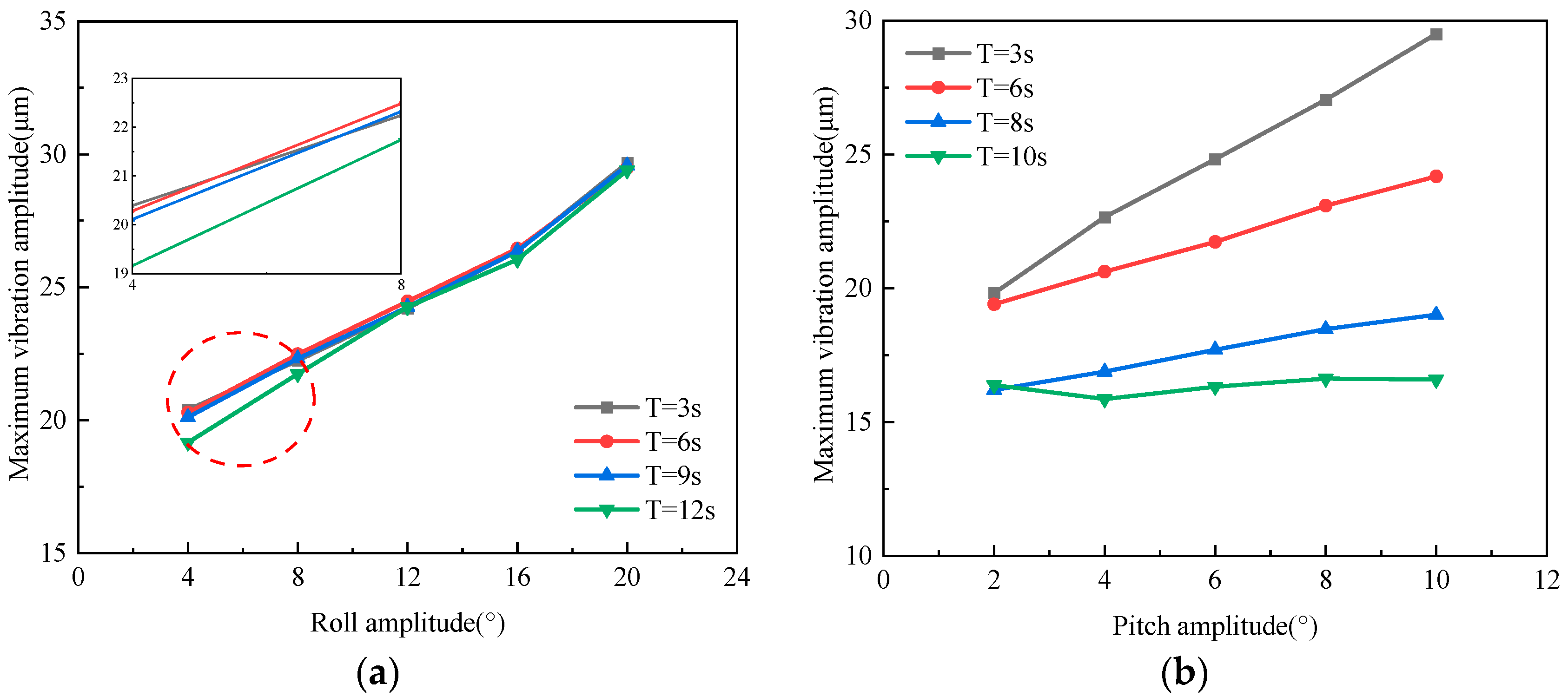
The maximum vibration amplitudes corresponding to the fundamental frequency under various roll motion conditions were extracted and are plotted in Figure 12. It can be observed that the fundamental frequency vibration amplitude of the rotor increases significantly with the increase in rocking amplitude. Under roll motion, when the roll amplitude increases from 4° to 20°, the corresponding fundamental frequency vibration amplitude rises sharply from 20 μm to 29 μm, representing an increase of 45%. In contrast, under pitch motion, when the pitch amplitude increases from 2° to 10°, the corresponding fundamental frequency vibration amplitude surges from 19 μm to 29 μm, reflecting a 52% increase. Notably, when the roll amplitude of the base remains constant, the fundamental frequency vibration amplitudes of the rotor under different rolling frequencies are nearly identical, with variations not exceeding 2 μm. However, under pitching motion, the variation trend of the fundamental frequency vibration amplitude of the rotor becomes more pronounced as the pitch frequency increases.
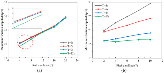
Figure 12.
Amplitude variation in fundamental frequency vibration with rocking amplitude: (a) roll motion; (b) pitch motion.
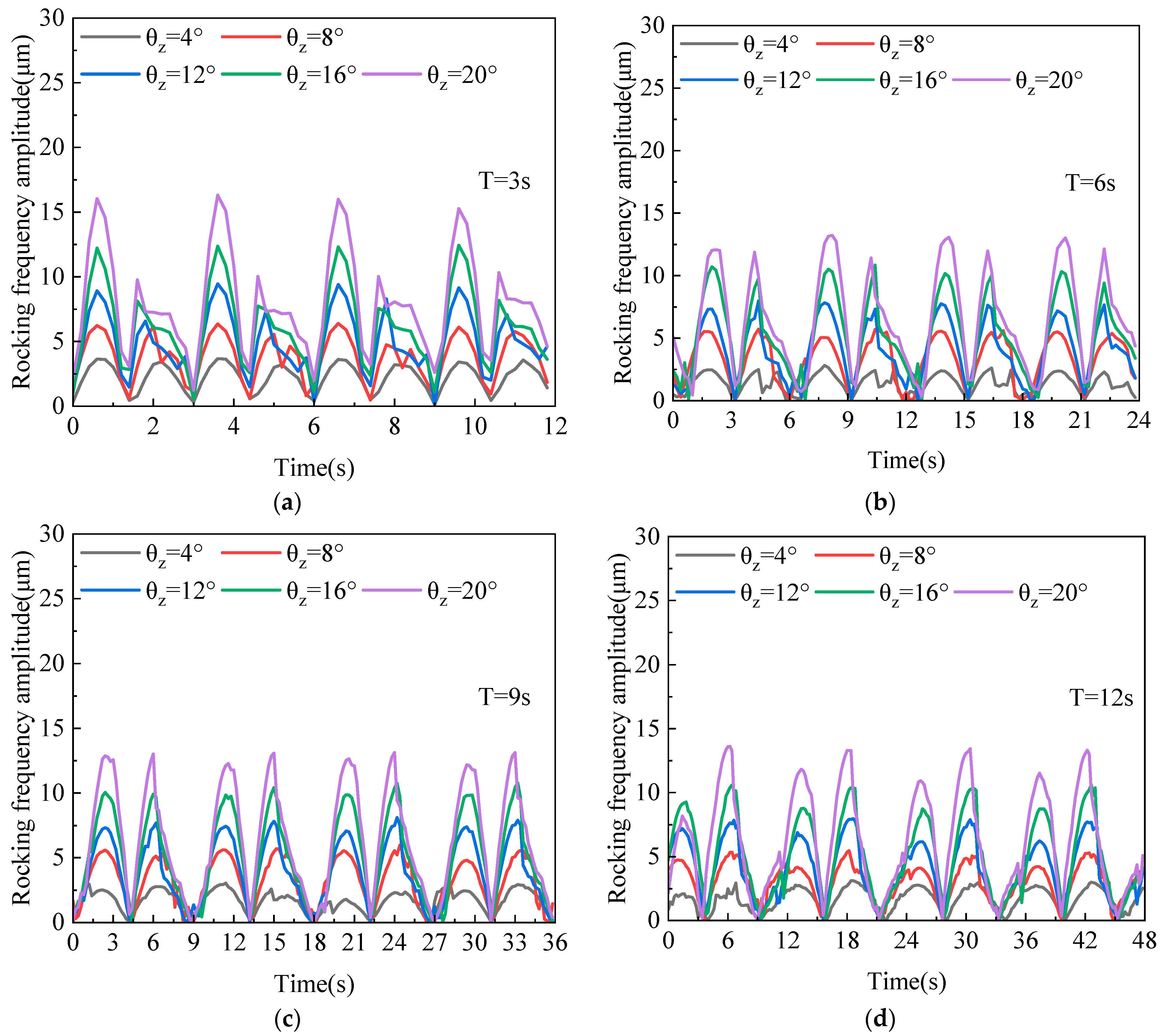
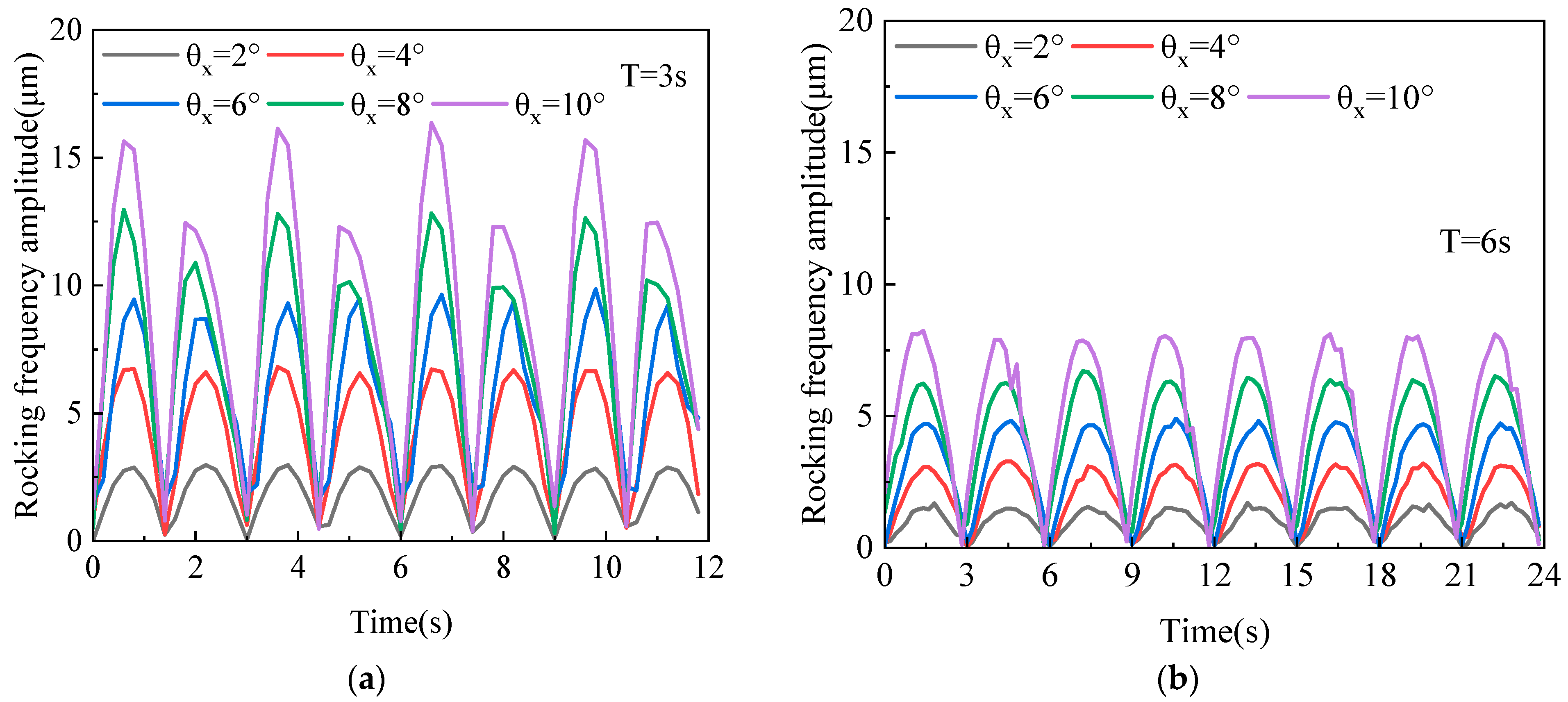
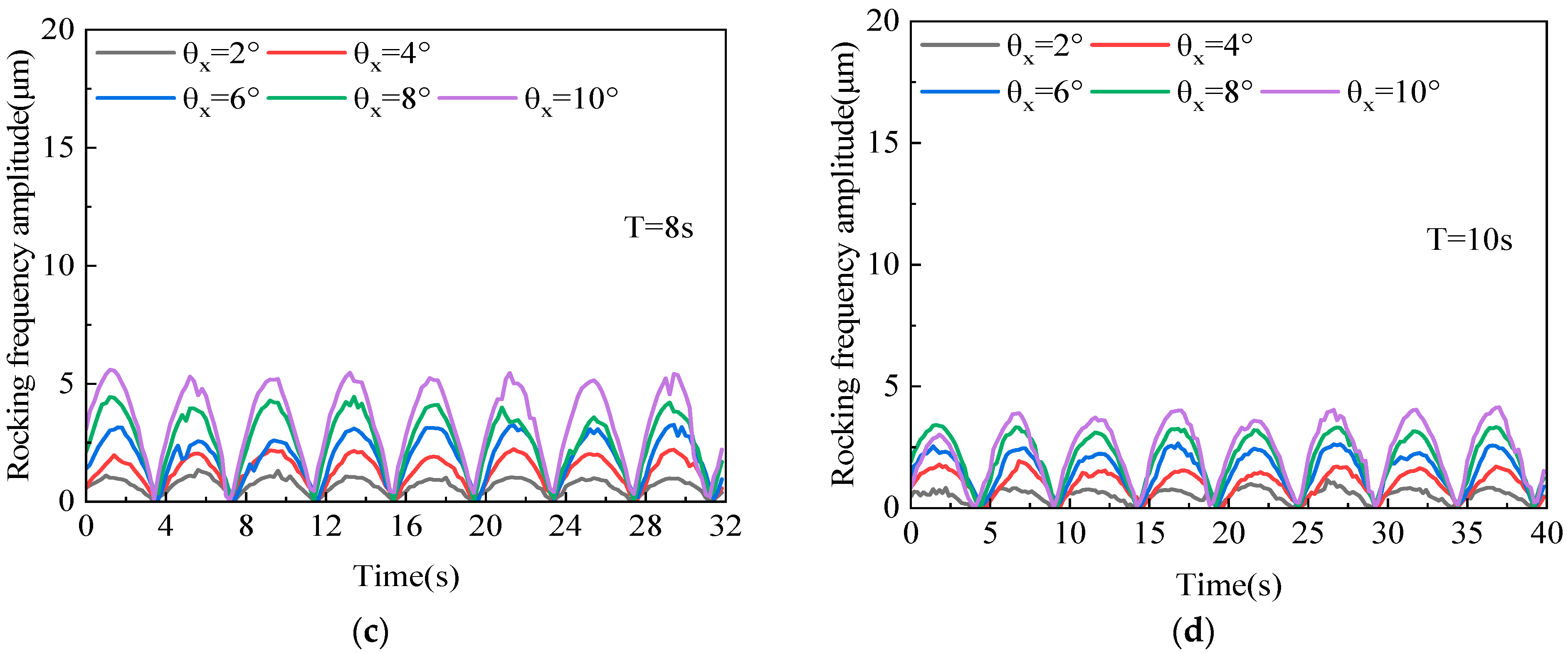
Figure 13 and Figure 14, respectively, illustrate the time-varying trends of the rocking frequency amplitude in the y-direction of the rotor system under different roll periods (3 s, 6 s, 9 s, 12 s) and pitch periods (3 s, 6 s, 8 s, 10 s). The results demonstrate that the rocking frequency amplitude of the rotor system exhibits frequency-synchronized periodic modulation with the base motion under both roll and pitch excitations. Notably, during roll excitation with fixed angular amplitude, the amplitude variation trends of rotor rocking frequency remain highly consistent across different roll periods, mirroring the characteristics observed in base-frequency vibration amplitude evolution. Conversely, under pitch excitation, a pronounced enhancement in amplitude variation trends emerges with increasing pitch frequency, revealing marked dynamic sensitivity to pitch-induced parametric excitation. This phenomenon further highlights the enhanced sensitivity of the rotor system to period variation in base pitch motion.
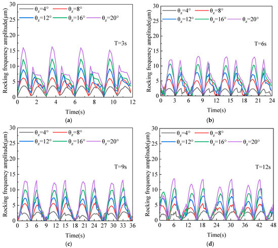
Figure 13.
Time-domain amplitude of rocking frequency amplitude under roll motion: (a) 3 s; (b) 6 s; (c) 9 s; (d) 12 s.
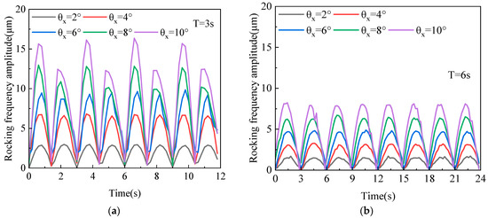
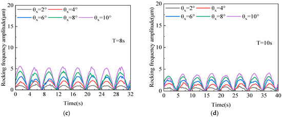
Figure 14.
Time-domain amplitude of rocking frequency amplitude under pitch motion: (a) 3 s; (b) 6 s; (c) 8 s; (d) 10 s.
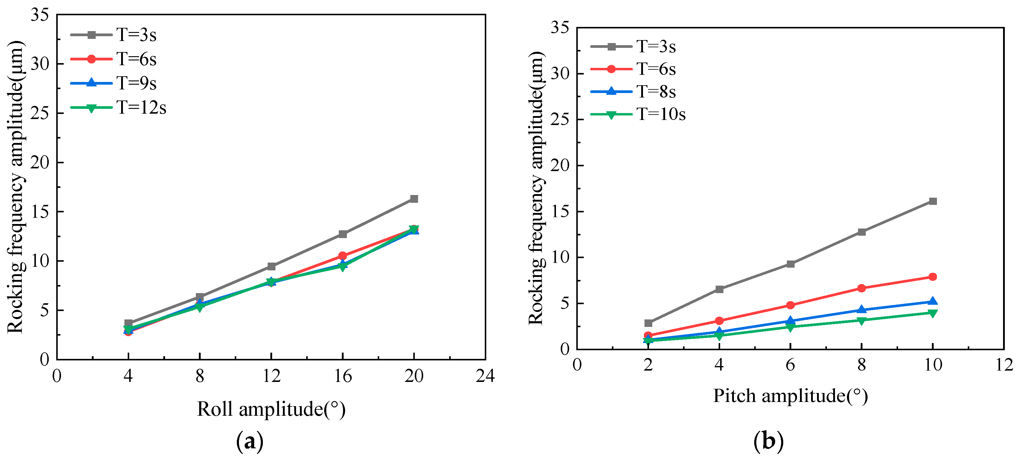
The maximum vibration amplitudes corresponding to the rocking frequencies under various rocking conditions are plotted in Figure 15. It is evident that the amplitude of the rotor system’s rocking frequency significantly increases with the increase in both rocking amplitude and frequency. Specifically, during base roll and pitch motions, as the rocking amplitudes increase from 4° to 20° and from 2° to 10°, respectively, the corresponding rocking frequency amplitudes escalate sharply from 3 μm to 15 μm, representing a 400% increase.
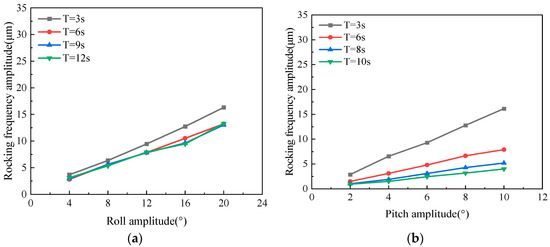
Figure 15.
Amplitude variation in rocking frequency vibration with rocking amplitude: (a) roll motion; (b) pitch motion.
Notably, for roll periods ranging from 12 s to 6 s, the rocking frequency amplitudes remain relatively constant. However, when the roll period decreases to 3 s, there is a marked rise in these amplitudes. Similarly, as the pitch periods decrease from 10 s to 6 s, the rocking frequency amplitudes increase gradually; a further reduction in the pitch period to 3 s leads to a significant enhancement in these amplitudes. This indicates that the angular acceleration of the base motion decreases significantly when the base roll and pitch periods are relatively long, resulting in a decrease in the amplitude of the additional excitation due to inertial forces in the coupled motion. However, as the period shortens, the base angular acceleration increases substantially, resulting in pronounced changes in the nonlinear oil film force characteristics, which ultimately trigger a significant amplification of the rotor’s vibration amplitude.
3.4. Influence of Pitch and Roll Motions on the Instability Speed of the System
Figure 16 presents waterfall plots of the system’s vibration along the y-direction under operating conditions with a period of 3 s, a roll amplitude of 20°, and a pitch amplitude of 10°. It can be observed from the figures that during the speed ramp-up of the rotor, low-frequency vibrations associated with the rocking motion persistently occur. When the rotor speed increases to a range of 5280–5400 r/min, a component at 1/3 of the fundamental frequency, which varies with rotational speed, is detected in the vibration spectrum of the shafting. Compared to the sub-synchronous whirl (0.42–0.5X) typically observed in traditional journal bearings, this frequency component is notably lower. This phenomenon may be attributed to the rocking motion accelerating lubricant leakage at both ends of the bearing bush.
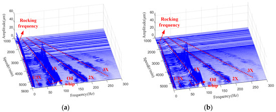
Figure 16.
Waterfall plot of the rotor under base rocking motion: (a) roll motion; (b) pitch motion.
Further observations reveal that when the rotor speed reaches 5400 r/min, the amplitude of the low-frequency vibration sharply increases to 10 μm. In Figure 16, in addition to the oil film whirl frequency and the rocking motion frequency, a low-frequency component corresponding to the critical speed also emerges. Current research defines the instability rotational speed of the shaft system of the base rocking motion as follows: the hull motion and the nonlinear bearing oil force produce low frequency at the same time, and the rotational speed at which the nonlinear bearing oil film force produces low frequency is the corresponding instability rotational speed [26]. Refer to this determination theorem. When the speed further increases to 5600 r/min, this frequency component remains constant, indicating the occurrence of “frequency locking”. This phenomenon suggests that oil film whip occurs at a rotor speed of 5400 r/min, leading to the loss of system stability.
To more clearly elucidate the influence of pitch and roll motions on the instability threshold speed of the rotor, the spectral characteristics within a complete rocking period at the onset of instability were extracted and analyzed under different experimental conditions.
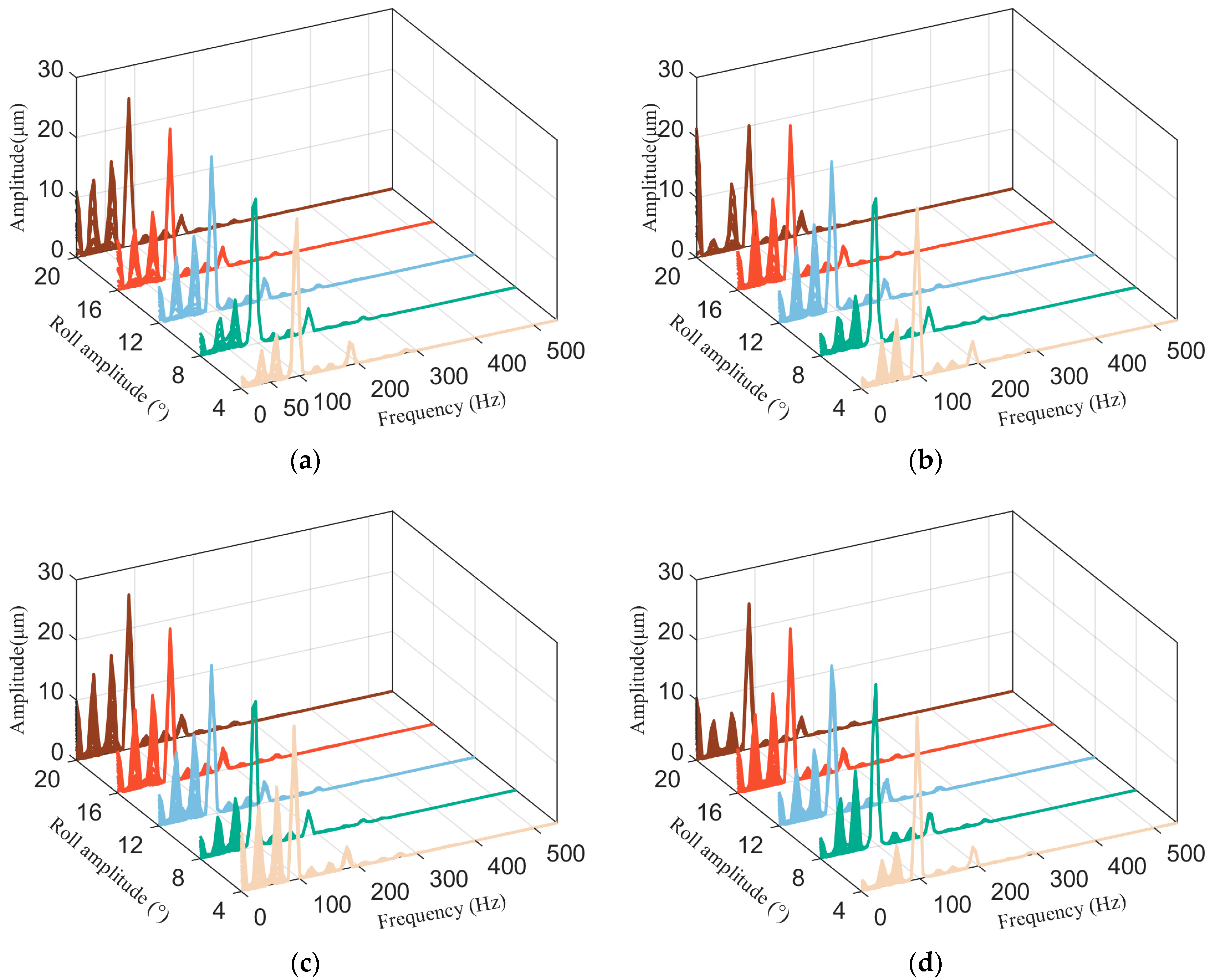
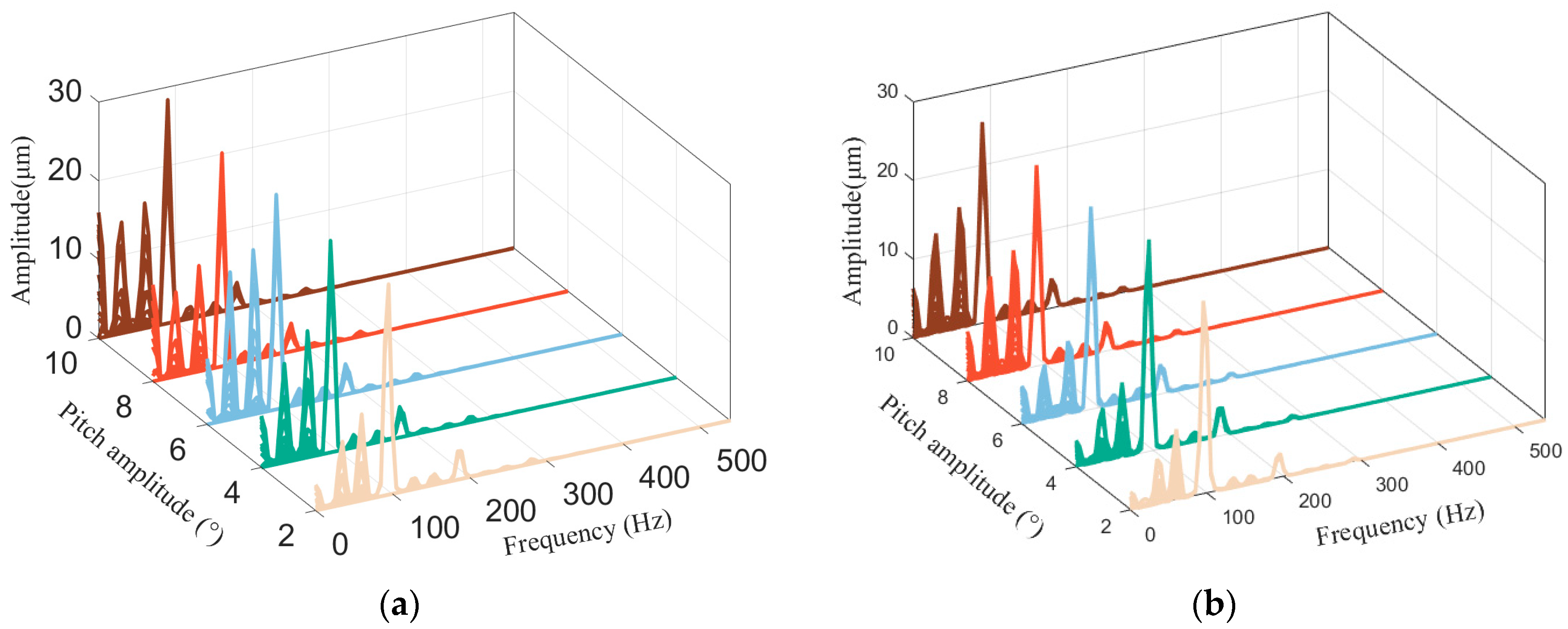
Figure 17 and Figure 18, respectively, present the spectral characteristics of the system in the y-direction under base roll and pitch motion conditions. From the figures, it can be observed that when the system enters an unstable state, the amplitude of the low-frequency vibrations of the rotor significantly increases. The low-frequency components are mainly concentrated at 30 Hz, 60 Hz, and the rocking frequency. Specifically, 30 Hz corresponds to 0.333X; 60 Hz is associated with the system’s first-order critical speed; and the rocking frequency is excited by the base motion. Furthermore, as discussed in Section 3.3, under constant rotational speed conditions, the vibration characteristics of the rotor within one complete rocking period vary periodically with the rocking amplitude. This indicates that during the instability process of the rotor, the low-frequency vibration components also ‘exhibit periodic behavior’.
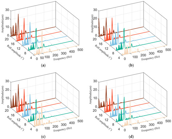
Figure 17.
Frequency spectrum of the system under roll motion: (a) 3 s; (b) 6 s; (c) 9 s; (d) 12 s.

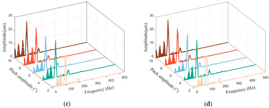
Figure 18.
Frequency spectrum of the system under pitch motion: (a) 3 s; (b) 6 s; (c) 8 s; (d) 10 s.
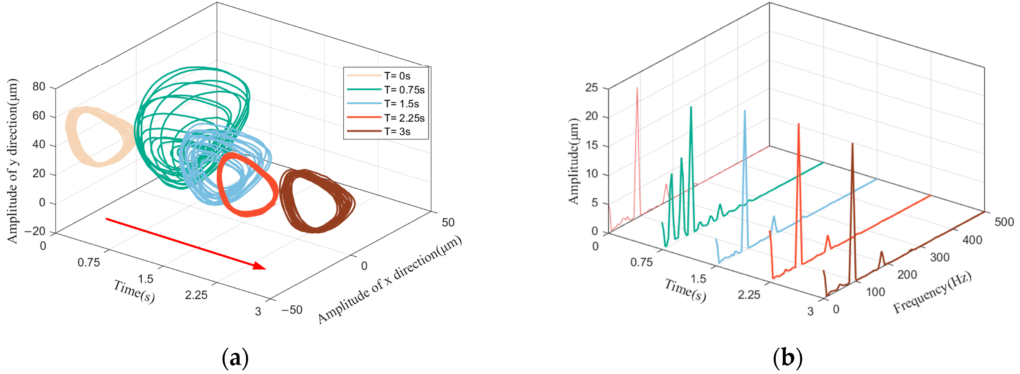
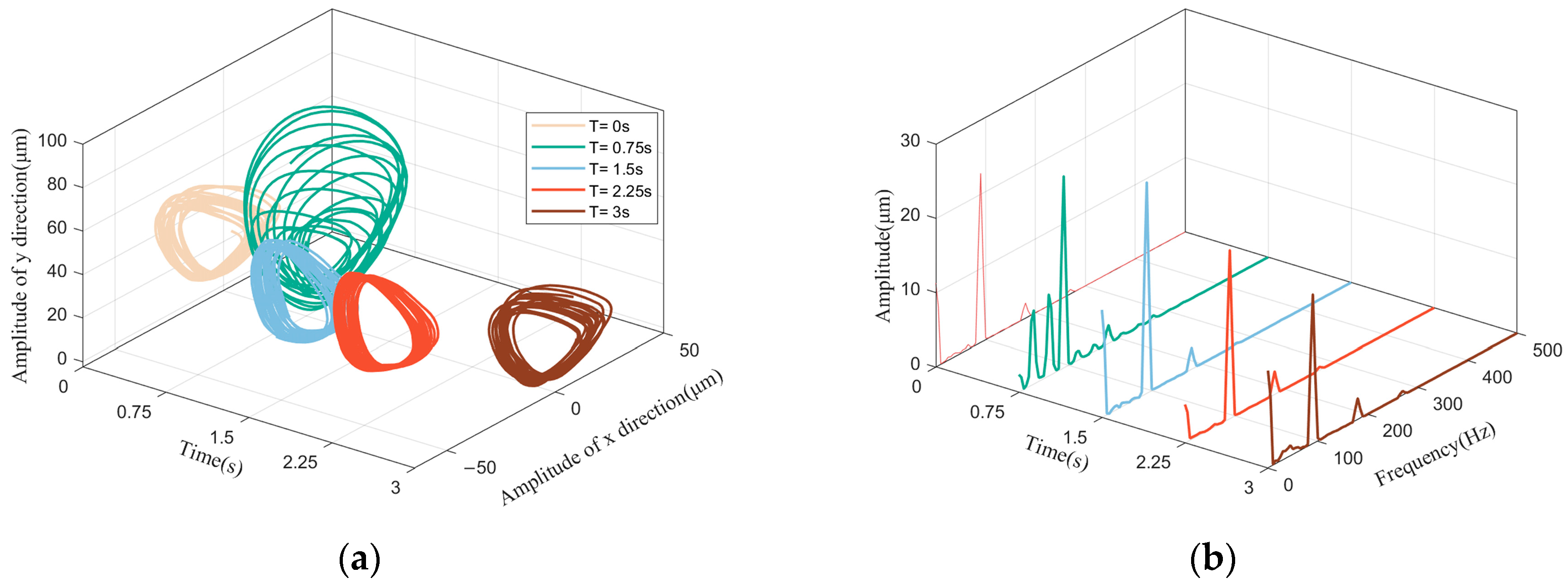
Figure 19 illustrates the dynamic evolution of the shaft center trajectory at various time points across a complete roll period under base roll excitation with an amplitude of 20° and a period of 3 s, during system instability. From Figure 19a, it can be observed that when the six-degrees-of-freedom platform is at its initial position (with a rocking amplitude of 0°), the rotor center trajectory exhibits an elliptical shape; as the platform undergoes roll motion, at 1/4 of the period, the rotor center trajectory evolves from an elliptical shape into a petal-like pattern; at 1/2 of the period, when the platform returns to its initial position, the rotor center trajectory reverts to an elliptical shape; at 3/4 of the period and at the end of the period, the rotor center trajectory remains elliptical. Figure 19b presents the corresponding rotor frequency spectrum at the same time instants; at 1/4 of the period, the amplitude of low-frequency oscillations in the system increases significantly, leading to instability. The dynamic response characteristics of the rotor system under pitch motion excitation are very similar to those under roll motion, as shown in Figure 20.

Figure 19.
Vibration response of the rotor system at different time instants during a single roll period: (a) shaft center orbit; (b) frequency spectrum.
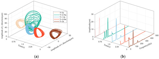
Figure 20.
Vibration response of the rotor system at different time instants during a single pitch period: (a) shaft center orbit; (b) frequency spectrum.
The above experimental results indicate that under time-varying rocking load excitation, when the rotational speed of the rotor approaches the instability threshold without base rocking (6060 r/min), the shaft center is subjected to alternating loads, causing it to deviate from its static equilibrium position and undergo large-scale displacement within the bearing clearance. At this point, the amplitude of the nonlinear oil film force increases sharply, accompanied by abrupt changes in direction, ultimately leading to “periodic intermittent instability” phenomena.
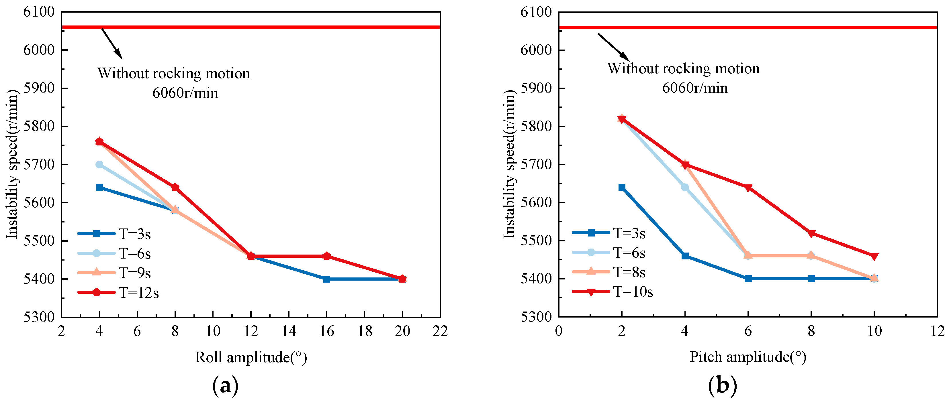
Figure 21 illustrates the trend of system instability speed as a function of rocking amplitude under different experimental conditions. The red reference line corresponds to the system’s instability speed (6060 r/min) without base rocking motion. Experimental data reveal that as the rocking amplitude and frequency increase, the stability of the rotor system deteriorates, and the instability threshold occurs earlier. Within the smaller range of rocking amplitudes (roll amplitudes from 4° to 12° and pitch amplitudes from 2° to 6°), the system’s instability speed decreases significantly. Under roll conditions, the instability speed of the shaft system drops from 5760 r/min to 5460 r/min, representing a reduction of 5.2%. Under pitch conditions, the instability speed decreases from 5820 r/min to 5400 r/min, with a reduction of 7.2%. As the rocking amplitude continues to increase, the declining trend of the instability speed gradually slows down and eventually stabilizes at 5400 r/min. Notably, when the rocking frequency increases, the base roll motion causes a gradual decline in the system’s instability speed, whereas the pitch motion exhibits a more pronounced reduction in instability speed.
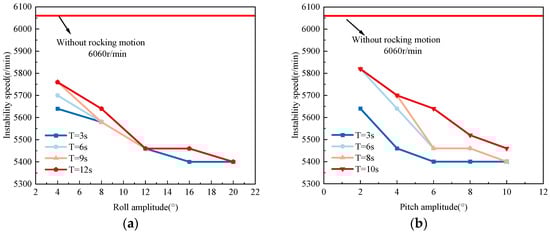
Figure 21.
Variation in system instability speed with rocking amplitude for different base motions: (a) roll motion; (b) pitch motion.
4. Conclusions
This study designed and constructed an experimental platform for a journal bearing-rotor system, applying pitch and roll excitation loads through a six-degrees-of-freedom (6-DOF) motion platform to systematically investigate the influence of rocking period and amplitude on rotor system stability. The main conclusions are as follows:
- (1)
- The base rocking motion introduces characteristic frequency components related to the excitation frequency to the system response.
- (2)
- With the increase in both the amplitude and frequency of the base rocking motion, the system vibration amplitude increases significantly.
- (3)
- The additional stiffness and damping introduced by base rocking excitation have negligible effects on the rotor system’s natural frequency, with the critical speed change remaining below 3.5%. However, under roll and pitch excitations, the resonance peak amplitude at the critical speed increases significantly, reaching 86% and 113%, respectively.
- (4)
- Unlike the instability mechanism under non-rocking base conditions, rocking load excitation reduces rotor system stability, and with increasing rocking amplitude and frequency, system stability significantly decreases.
This study assumes sinusoidal motion of the ship and ignores ocean stochasticity. Future work will integrate six-degrees-of-freedom platforms with stochastic rocking and extend the theoretical model to improve the research system and enhance engineering applicability.
Author Contributions
Conceptualization, F.X.; investigation, K.Z.; resources, G.W.; writing—original draft preparation, J.W.; supervision, J.Y.; project administration, Z.X. All authors have read and agreed to the published version of the manuscript.
Funding
This research was funded by the Specialized Basic Research Projects of China (Grant No. J2019-IV-0021), National Key Laboratory of Nuclear Reactor Technology, Nuclear Power Institute of China (YESW-0224-0101-21-01) and the Fundamental Research Funds for the Central Universities (Grant No. DUT24GF111).
Data Availability Statement
Data is contained within the article.
Acknowledgments
The authors are grateful to the reviewers for their careful and detailed comments.
Conflicts of Interest
The authors declare no conflicts of interest.
References
- Nayfeh, A.H.; Mook, D.T.; Marshall, L.R. Nonlinear Coupling of Pitch and Roll Modes in Ship Motions. J. Hydronautics 1973, 7, 145–152. [Google Scholar] [CrossRef]
- Ibrahim, R.A.; Grace, I.M. Modeling of Ship Roll Dynamics and Its Coupling with Heave and Pitch. Math. Probl. Eng. 2010, 2010, 1192–1269. [Google Scholar] [CrossRef]
- Lund, J.W. Calculation of Stiffness and Damping Properties of Gas Bearings. J. Tribol. 1968, 90, 793–803. [Google Scholar] [CrossRef]
- Glienicke, J. Experimental Investigation of the Stiffness and Damping Coefficients of Turbine Bearings and Their Application to Instability Prediction. Proc. Inst. Mech. Eng. Conf. Proc. 1966, 181, 116–129. [Google Scholar] [CrossRef]
- Lin, R.; Hou, L.; Zhong, S.; Chen, Y. Nonlinear Vibration and Stability Analysis of a Dual-Disk Rotor-Bearing System under Multiple Frequency Excitations. Nonlinear Dyn. 2024, 112, 12815–12846. [Google Scholar] [CrossRef]
- Xue, W.; Shen, J.; Fan, Y. Study on Dynamic Characteristics of Acceleration Process of Spherical Hybrid Sliding Bearings Rotor System. Ind. Lubr. Tribol. 2024, 76, 365–373. [Google Scholar] [CrossRef]
- Xie, Z.; Jiao, J.; Zhao, B.; Zhang, J.; Xu, F. Theoretical and Experimental Research on the Effect of Bi-Directional Misalignment on the Static and Dynamic Characteristics of a Novel Bearing. Mech. Syst. Signal Process. 2024, 208, 111041. [Google Scholar] [CrossRef]
- Xie, Z.; Li, J.; Tian, Y.; Du, P.; Zhao, B.; Xu, F. Theoretical and Experimental Study on Influences of Surface Texture on Lubrication Performance of a Novel Bearing. Tribol. Int. 2024, 193, 109351. [Google Scholar] [CrossRef]
- Xie, Z.; Jiao, J.; He, T.; Xu, F.; Zhang, J. Lubrication Behaviors of a Novel Bearing with Fluid-Solid-Thermal (FST) Approach: Experimental and Theoretical Investigation. Tribol. Int. 2023, 185, 108481. [Google Scholar] [CrossRef]
- Xie, Z.; Zhao, B.; Lu, K.; Zhou, K.; Du, P.; Liang, P.; Xu, F. An In Situ Vibration Monitoring for a Special-Structure Bearing. JSEN 2025, 25, 3014–3029. [Google Scholar] [CrossRef]
- Larsen, J.S.; Santos, I.F. On the Nonlinear Steady-State Response of Rigid Rotors Supported by Air Foil Bearings—Theory and Experiments. J. Sound Vib. 2015, 346, 284–297. [Google Scholar] [CrossRef]
- Jin, X.; Zhou, W.; Ma, J.; Su, H.; Liu, S.; Gao, B. Analysis on the Vibration Signals of a Novel Double-Disc Crack Rotor-Bearing System with Single Defect in Inner Race. J. Sound Vib. 2025, 595, 118729. [Google Scholar] [CrossRef]
- Wang, R.; Guo, X.; Wang, Y. Nonlinear Analysis of Rotor System Supported by Oil Lubricated Bearings Subjected to Base Movements. Proc. Inst. Mech. Eng. Part C J. Mech. Eng. Sci. 2016, 230, 543–558. [Google Scholar] [CrossRef]
- Liu, Z.; Liu, Z.; Li, Y.; Zhang, G. Dynamics Response of an On-Board Rotor Supported on Modified Oil-Film Force Considering Base Motion. Proc. Inst. Mech. Engineers. Part C J. Mech. Eng. Sci. 2018, 232, 245–259. [Google Scholar] [CrossRef]
- MajidiRad, A.; Yihun, Y.S. Experimental and Numerical Investigation of Residual Stress Stiffening Influence on Dynamic Response of Welded Structures; American Society of Mechanical Engineers: New York, NY, USA, 2019. [Google Scholar]
- Zhang, B.; Chen, X.; Xiang, F.; Gan, X.; Ren, G. Dynamic Characteristics of Rotor-SFD-Support System Excited by Base Harmonic Excitations Using MHB-AFT Method; American Society of Mechanical Engineers: New York, NY, USA, 2022. [Google Scholar]
- Jarroux, C.; Mahfoud, J.; Dufour, R.; Legrand, F.; Defoy, B.; Alban, T. Dynamic Behavior of a Rotor-AMB System Due to Strong Base Motions; Cavalca, K.L., Weber, H.I., Eds.; Springer International Publishing AG: Cham, Switzerland, 2019; Volume 62, pp. 340–349. ISBN 2211-0984. [Google Scholar]
- Dakel, M.; Baguet, S.; Dufour, R. Nonlinear Dynamics of a Support-Excited Flexible Rotor with Hydrodynamic Journal Bearings. J. Sound Vib. 2014, 333, 2774–2799. [Google Scholar] [CrossRef]
- Dakel, M.; Baguet, S.; Dufour, R. Steady-State Dynamic Behavior of an on-Board Rotor under Combined Base Motions. JVC/J. Vib. Control 2014, 20, 2254–2287. [Google Scholar] [CrossRef]
- Han, Y.; Li, M. Nonlinear Dynamic Characteristics of Marine Rotor-Bearing System under Heaving Motion. Shock Vib. 2019, 2019, 7683952. [Google Scholar] [CrossRef]
- Zhang, W.; Li, M. Nonlinear Dynamic Characteristics of Marine Rotor-Bearing System under Coupled Heave and Pitch Ship Motions. Proc. Inst. Mech. Engineers. Part C J. Mech. Eng. Sci. 2022, 236, 63–79. [Google Scholar] [CrossRef]
- Zhao, W.; Xiao, L.; Li, M. Nonlinear Dynamic Behaviors of a Marine Rotor-Bearing System Coupled with Air Bag and Floating-Raft. Shock Vib. 2015, 2015, 1–18. [Google Scholar] [CrossRef]
- Tong, Z.; Hu, Y.; Tong, S.; Jiang, Y.; Song, B. Dynamic Modeling of Spur Gear System under Marine Ship Heaving-Pitching Motion. Ocean Eng. 2023, 283, 115069. [Google Scholar] [CrossRef]
- Lin, F.; Meng, G. Study on the Dynamics of a Rotor in a Maneuvering Aircraft [ASME J. Vib. & Acous., 125, No. 3, pp. 324–327]. J. Vib. Acoust. 2004, 126, 322–323. [Google Scholar] [CrossRef]
- Gaganis, B.J.; Zisimopoulos, A.K.; Nikolakopoulos, P.G.; Papadopoulos, C.A. Modal Analysis of Rotor on Piecewise Linear Journal Bearings Under Seismic Excitation. J. Vib. Acoust. 1999, 121, 190–196. [Google Scholar] [CrossRef]
- Guanghui, Z.; Shupeng, L.; Ruixian, M.; Zhansheng, L. Nonlinear Dynamic Characteristics of Journal Bearing–Rotor System Considering the Pitching and Rolling Motion for Marine Turbo Machinery. Proc. Inst. Mech. Engineers. Part M J. Eng. Marit. Environ. 2015, 229, 95–107. [Google Scholar] [CrossRef]


Disclaimer/Publisher’s Note: The statements, opinions and data contained in all publications are solely those of the individual author(s) and contributor(s) and not of MDPI and/or the editor(s). MDPI and/or the editor(s) disclaim responsibility for any injury to people or property resulting from any ideas, methods, instructions or products referred to in the content. |
© 2025 by the authors. Licensee MDPI, Basel, Switzerland. This article is an open access article distributed under the terms and conditions of the Creative Commons Attribution (CC BY) license (https://creativecommons.org/licenses/by/4.0/).