Abstract
Carbon fiber reinforced polymers (CFRPs) are significantly vital for industries. However, the drilling process of a CFRP is considered a challenge due to its nature, which causes delamination, fiber pull-out, peel-up, high friction, and a decrease in cutting tool life. Wet drilling is necessary for minimizing defects, and lubricants are very costly. In the current work, ultrasonic-assisted drilling (UAD) with a longitudinal vibration of 39.7 kHz was applied to the drill bit in the feed direction, used for CFRPs, and compared with conventional drilling (CD). Low spindle speeds under 5000 rpm were applied with different feed rates. The morphology, delamination factor, and cutting forces were investigated through the specific input machining parameters for CD and UAD. SEM was applied to study the morphology of the hole entrance and exit as well as the burr heights of evacuated chips. UAD with 39.7 kHz succeeded in minimizing the surface roughness by 50% compared with the surface roughness resulting from CD and could drill high-precision holes for CFRPs with a trade-off concept, besides achieving near-zero delamination (K ≃ 1) in the absence of a lubricant, which is being extended for industrial application.
1. Introduction
Nowadays, the demand for carbon fiber reinforced polymer (CFRP) composites in the industry has increased due to their multiple uses, resulting from their perfect mechanical properties [1]. In the case of comparing CFRPs with similar composite families, CFRPs can be used for designing and manufacturing critical components because of the high specific stiffness, high specific strength [2], excellent thermal stability, and superior corrosion resistance. CFRP composites are suitable as a structural material and are attached to other metals or steels through mechanical attachments [3]. Generally, the characteristics of CFRPs are unique and they possess excellent behavior. CFRPs show a lightweight [4], high weight ratio, and stiffness-to-weight, which are mostly required for industrial applications [1].
There is increasing demand for CFRP composite materials for applications in advanced structures because of their high strength and stiffness compared with other materials including metals. CFRPs have been widely used in high-tech industries due to their unique performance [5] and have many application areas such as aerospace [6], aircraft [7], sporting goods, marine [8], automotive industries [9], satellite antennas, wheelchairs, and computer body panels [10]. Moreover, electronic components, such as circuit boards, use these composites. CFRPs, including implants and prosthetic limbs, are also used in the medical industry [8]. However, the automotive and aerospace industries are the key sectors implementing these materials [1].
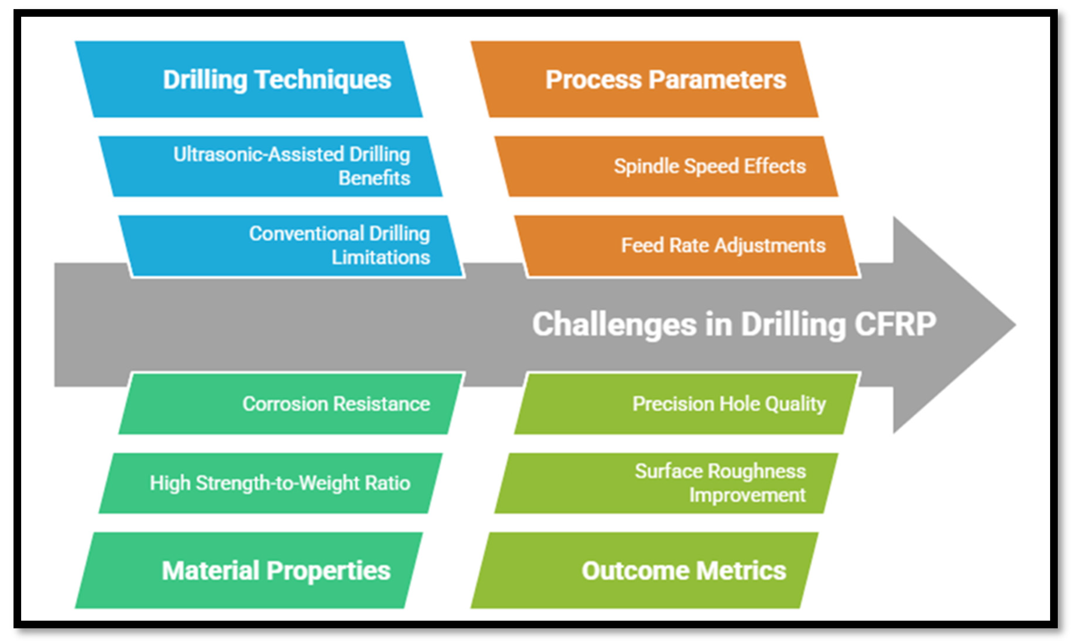
Machining processes are an effective technique in creating products of high precision and suitable surface roughness [11]. Traditional drilling is involved in many applications of CFRPs [12], and it is commonly accepted for manufacturing and assembly structures made of CFRPs [13]. Even though they are cured to the ultimate shape, mechanical drilling becomes a need at some stage in the manufacturing of CFRPs to assemble parts using bolts and rivets [14]. However, the conventional drilling operation for CFRP laminates is more exposed to damage through the cutting process [1]. During mechanical drilling, CFRPs tend to display several defects on machined surfaces, such as fiber pullout, delamination, fuzzing, spalling, and fiber breakout, due to the characteristics of the material, unsuitable selection of drilling conditions, tool geometry, and tool materials [5]. Induced damage due to the drilling process is a vital issue related to CFRP manufacturing as it negatively influences the performance of the finished machined composite parts. Thermomechanical effects are generated due to the contact of twist-drill edges alternately with the reinforcing fibers and the matrix base during the drilling process. Moreover, there are various mechanisms of matrix and fiber removal that always differ with the fiber layup, even under the action of identical cutting edges. Tearing, burrs, delamination, glass transition failure, surface cavities [3], spalling, edge chipping, crack formation, fiber pullout, and excessive tool wear [8] are series defects and mostly occur to decrease the quality of produced parts [3]. In some critical machined parts of aerospace components, delamination is considered the main reason for rejection [1]. Among the mentioned defects, delamination is the most common and serious type of damage during composite material drilling [15]. The feed rate and spindle speed as input parameters mainly affect the surface roughness and delamination [1]. Therefore, the machining of CFRPs must counter a series of challenges in tool wear resistance and quality control as a result of their inherent heterogeneity and abrasiveness, which lead to severe workpiece damage and serious tool wear [16]. Figure 1 shows some of the characteristics of drilling CFRPs.

Figure 1.
Drilling techniques and their effects on CFRP machinability.
Nowadays, ultrasonic vibration-assisted drilling is a novel hybrid machining process. UVAD is used to recover the defects of conventional drilling and for drilling hard-to-cut materials such as CFRPs, titanium, and Inconel 738. UVAD is a nonconventional drilling process. A high-frequency axial vibration is applied to the tool end while it rotates and feeds into the workpiece [17]. UVAD has been found to reduce the cutting force in drilling CFRPs [14]. Ultrasonic vibration with low amplitude in UAD is incorporated into the drill bit movement in the feed direction, which is one of the common representatives of advanced drilling techniques. In recent years, many studies have been conducted on UVAD that have obtained an excellent drilling performance [18]. Figure 2 shows the different types of ultrasonic vibration directions compared with conventional drilling [19].
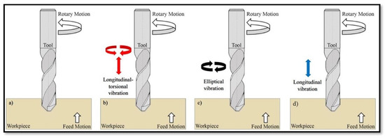
Figure 2.
Conventional drilling and various types of UAD. (a) Conventional drilling (CD), (b) UAD with longitudinal-torsional vibration, (c) UAD with elliptical vibration, and (d) UAD with longitudinal vibration [19].
Rendi Kurniawan et al. [20] researched ultrasonic vibration-assisted drilling (UVAD) for the micro-drilling of silicon wafers using numerical and analytical approaches. They were concerned with the comprehension of micro-cracking mechanisms under the mechanical process, cutting force, micro-fracture analysis, and cutting energy. The numerical approach predicted micro-cracks in the brittle regime, while the analytical approach developed a model to predict lines of brittle–ductile transitions. They demonstrated that UVAD reduced micro-fractures on the drilled micro-hole side, particularly at very low feed rates per revolution. J. Xu et al. [3] studied drilling-induced damage in CFRPs by observing the formation mechanism of damage, classification, evaluation, and suppression. They also introduced the elementary effect of process parameters, tool geometry/matter, cutting conditions, and process strategies on composite damage formation and evolution. Jinyang Xu et al. [16] discussed the machinability evaluation of a type of high-strength T800/X850 CFRP commonly used in aircraft parts. Drilling forces, hole geometry, workpiece damage, precision of the hole size, and tool wear were examined. Moran Xu et al. [21] enhanced the machinability of Inconel 718 using longitudinal ultrasonic vibration-assisted milling with a high-frequency vibration spindle. They designed a spindle that improved the cutting force, surface quality, and tool life and demonstrated that the cutting force and temperature were reduced as well as improved surface integrity and increased machining efficiency compared with conventional methods. The study aimed to optimize ultrasonic spindles with high precision using high-frequency vibration through simulation and experiments, providing a new approach for the high-quality, efficient, and eco-friendly machining of hard-to-cut materials including Inconel 718. V. Krishnaraj et al. [22] investigated the drilling of CFRP laminates using K20 carbide as a cutting tool to study the effect of high cutting speed with various machining parameters on the hole diameter, circularity, delamination, and cutting forces. They demonstrated that the lowest tool wear rate until 150 holes was with 12,000 rpm as the spindle speed and 0.137 mm/rev as the feed rate. Moreover, the 2000 rpm spindle speed is best for circularity, whereas the feed rate has a great influence on the cutting forces. Kyung-Hee Park et al. [23] studied and compared the tool wear mechanism beside the hole quality during drilling CFRP versus CFRP-Ti stacks. The effect of the presence of titanium on the drilling process was studied. They demonstrated that drilling CFRP-Ti stacks resulted in more pronounced entry delamination, hole diameter errors, and surface roughness compared with drilling the CFRP only. This suggests that the addition of titanium negatively impacts the quality of the drilled holes. Tool wear was increased during the drilling of CFRP-Ti stacks. Moran Xu et al. [24] investigated the ultrasonic-assisted drilling (UAD) technique applied to CFRPs and titanium alloy stacks. Machinability and hole quality were studied by applying the finite element method for understanding the mechanical and thermal interactions during the drilling process. They found that UAD reduced the cutting forces by 27.2% compared with conventional drilling (CD) methods, and the tool wear resistance was increased by UAD. P. Li et al. [25] investigated the resulting drilling force and defects of drilling CFRPs using rotary ultrasonic longitudinal torsional vibration drilling (RULTVD). RULTVD decreased the cutting forces by 17.8% compared with conventional drilling, while the maximum delamination factor was reduced by 8.6%. Song Dong et al. [26] studied the cutting temperature of drilling CFRPs in robotic rotary ultrasonic drilling with the minimum quantity of lubrication (MQL). A theoretical prediction model for cutting temperature during the MQL process was established. Validation experiments were carried out with an average relative prediction error of only 9.12%.
P. Xu et al. [27] discussed the performance of high-frequency ultrasonic vibration-assisted drilling (HFUAD) in ceramic matrix composites (CMCs) compared with conventional drilling (CD) and normal ultrasonic vibration-assisted drilling (UAD). CMCs are hard and brittle, posing challenges like tool wear, drilling damage, and low hole accuracy. The study demonstrated that HFUAD significantly enhanced the machining outcomes by reducing the cylindricity errors by 65% and 29% compared with CD and UAD, respectively. Furthermore, HFUAD decreased the drilling forces by 81% and 48%, extended tool life by over 3.3 and 2.5 times, and reduced the subsurface damage by 49% and 21% compared with CD and UAD, respectively. These improvements arose from the greater contact angle between the grains and fibers, better stress distribution, and enhanced chip removal. The findings recognize HFUAD as a promising method for achieving low damage and high precision in CMC hole machining. Chen Hu et al. [28] investigated the influence of UAD on the minimization of defects in CFRPs with various hole diameters. They concluded that the optimal ultrasonic power (50%) minimized defects, with larger diameters having fewer fibers remaining uncut but poor tearing. It was demonstrated that UAD significantly improved the minimization of cutting forces, leading to enhanced hole quality. They optimized the appropriate machining parameters to improve the manufacturing drilling of CFRP components in the aerospace and automobile sectors. Peng Ji et al. [29] studied the UAD of CFRPs and highlighted its advantages in enhancing the quality of machining. The high-frequency vibrations facilitated the fracture and removal of brittle fibers and enhanced surface quality. The findings suggest optimal drilling conditions of a high spindle speed and a low feed rate for effective CFRP processing. M. Waseem et al. [30] investigated the influence of cryogenic cooling on delamination during the drilling of CFRP and Al 2024 stacks. Experimental and modeling approaches indicate that spindle speed is critical in delamination, with the best value of a reduction of 3.88% being achieved under cryogenic cooling conditions. Usage of nitrogen cooling enhanced hole quality by minimizing thermal damage and tool wear, leading to smooth surfaces. The findings suggest that cryogenic cooling is advantageous for improved drilling performance and cost reduction in manufacturing operations of CFRP/Al 2024 stacks for academic and industrial applications.
While 20–30 kHz is the normal choice in UAD, the current work applied 39.7 kHz to benefit from shorter vibration cycles in overcoming the brittleness of the CFRP fiber and minimizing delamination with minimal trade-off in force. Additionally, the frequency aligned with the industrial goals and applications.
2. Experimental Setup
Cutting ceramics are used industrially for creating cutting tools that can withstand critical mechanical and thermal load conditions during the machining of hard-to-cut materials [31]. Therefore, the cutting tool material was chosen to be uncoated and made from tungsten carbide (PANGDRILL, DPPA01060) with a 6 mm diameter. The CFRP was a drill workpiece and was a 10 mm-thick unidirectional plate. The reinforcing fiber was Toray-T800S in the same direction, and the epoxy matrix was Toray 250F. Fibers were in the same direction.
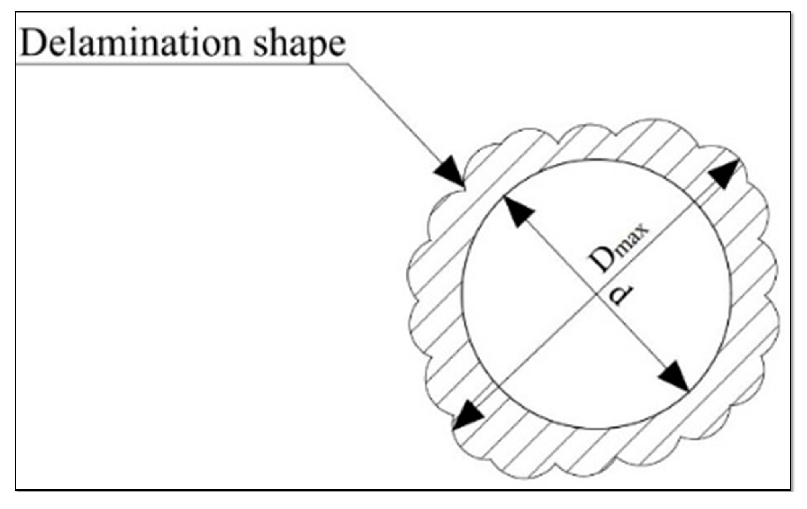
Experiments were conducted on a KVC800/1 Vertical Machining Center 4-axis (Changzheng Machine Tool Group, China). Machining conditions were utilized for optimizing the CFRP drilling conditions identified by Peng Ji et al. [29] at low feed rates (≤0.03 mm/rev) and spindle speeds <5000 rpm with reduced defects. Dry cutting feasibility was conducted to emphasize UAD’s eco-friendly potential [13,28] and high-frequency UAD’s capability in brittle materials [27]. Therefore, the machining parameters were selected as 1000, 3000, and 5000 rpm for the cutting speed, and the values of 0.01. 0.02 and 0.03 mm/rev as the feed rate. Every experiment was repeated 3 or 4 times to optimize the correct result and minimize error bars. All experiments were carried out with conventional drilling (CD) and then compared with experiments using ultrasonic-assisted vibration (UAD). The UAD system utilized purely longitudinal vibrations at 39.7 kHz without hybrid torsional or elliptical components with low amplitude, as shown in Figure 2d. All experiments were conducted under dry conditions. Table 1 shows the machining parameters used for drilling the CFRP. The cutting forces were measured using the Kistler 9272 (Kistler Instrumente AG, Winterthur, Switzerland, a Swiss company) as a dynamometer and a Kistler 5080A multifunctional amplifier charger. The force signals were sampled with a 32-bit PC-based data acquisition system. A digital microscope system (KEYENCE VHX-500FE) was used to observe the hole entry and exit morphology. SEM was also applied to monitor the morphology of the created hole. In order to study the morphology through the delamination phenomenon, the delamination factor (k) was used with the value of the maximum diameter (Dmax) divided by the nominal diameter (d), as shown in Figure 3 and Equation (1). Figure 4 shows the whole setup for the machining process.

Table 1.
Machining parameters.
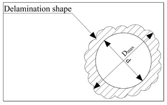
Figure 3.
Delamination schematic resulting from the drilling of the CFRP.
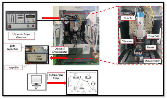
Figure 4.
Experimental setup for the drilling operation.
Uncertainties for all key parameters were precisely defined. Cutting forces, as measured by the Kistler 9272 dynamometer, had a ±1 N uncertainty, and delamination factors (K) had a ±0.015 uncertainty using Keyence VHX-500FE digital microscopy. For surface roughness and SEM measurements, when model numbers of the instruments were not stated, industry-standard practices were followed to achieve ±0.2 µm and ±0.6 µm accuracy, respectively. All of the margins of error were validated by repeated calibration testing and inter-operator testing; data points on numbers are the mean values ±1 standard deviation of 3–4 replicate tests.
3. Results and Discussion
3.1. Morphology for Hole Entrance and Exit
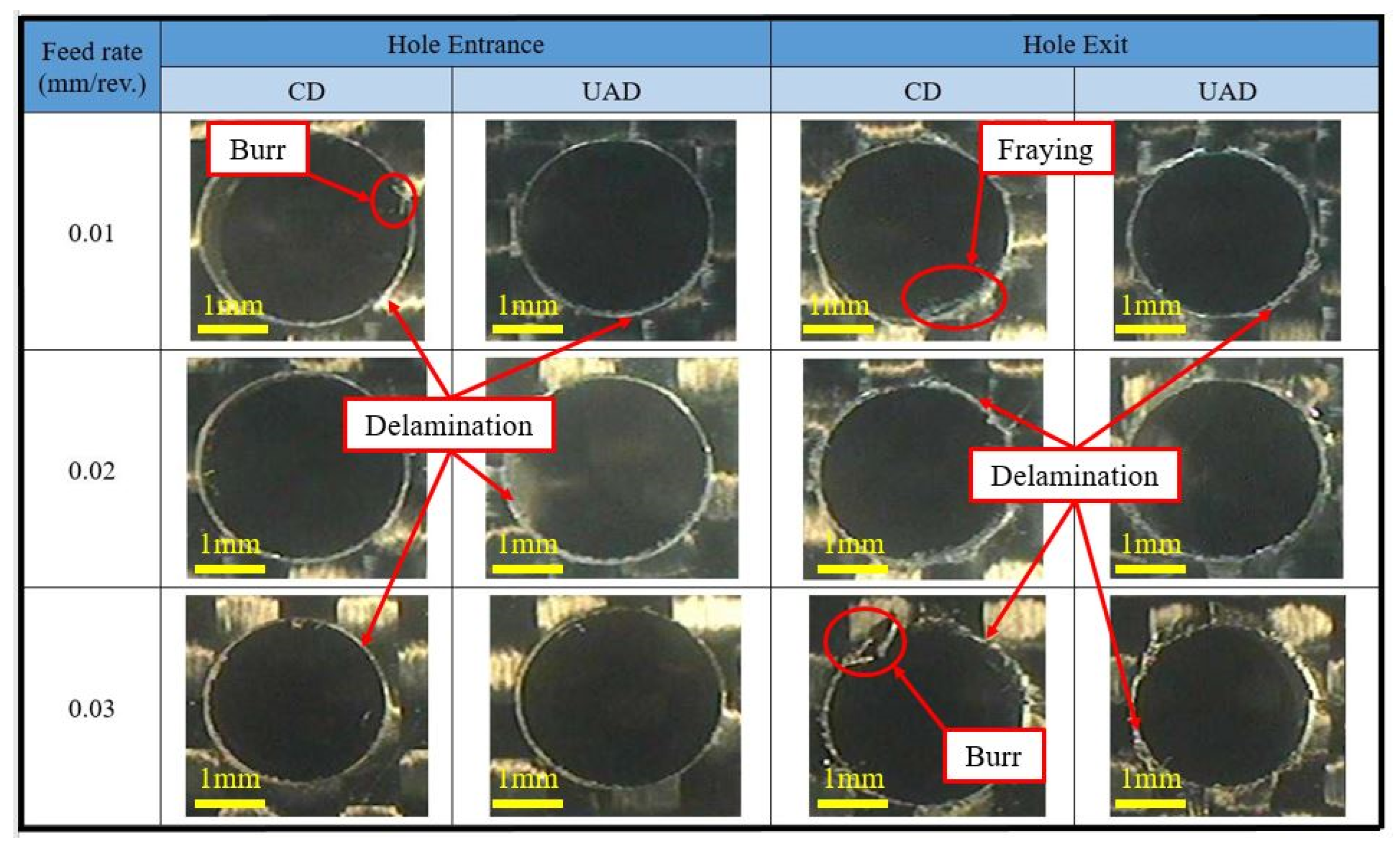
Figure 5 shows the experimental results of the hole entrance and exit morphology at 1000 rpm. The results compared the applied conventional drilling (CD) and ultrasonic assisting drilling (UAD) hybrid method for the CFRP. The data are presented by ordering the feed rate by 0.01, 0.02, and 0.03 mm/rev through CD and UAD. In the case of the hole entrance morphology, the hole circularity of the machined holes suited UAD and even CD. Delamination appeared clearly in CD and UAD with various parameters. Ultrasonic assisting drilling decreased the delamination factor, as shown in Figure 5. Burrs appeared in CD and UAD, however, UAD decreased this phenomenon. From monitoring the exit holes, it was noticed that the circularity distortion was quite clear in CD and decreased in UAD.
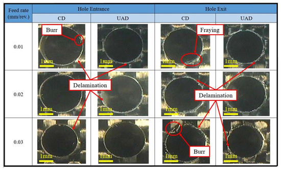
Figure 5.
Morphology of the hole entrance and exit at 1000 rpm.
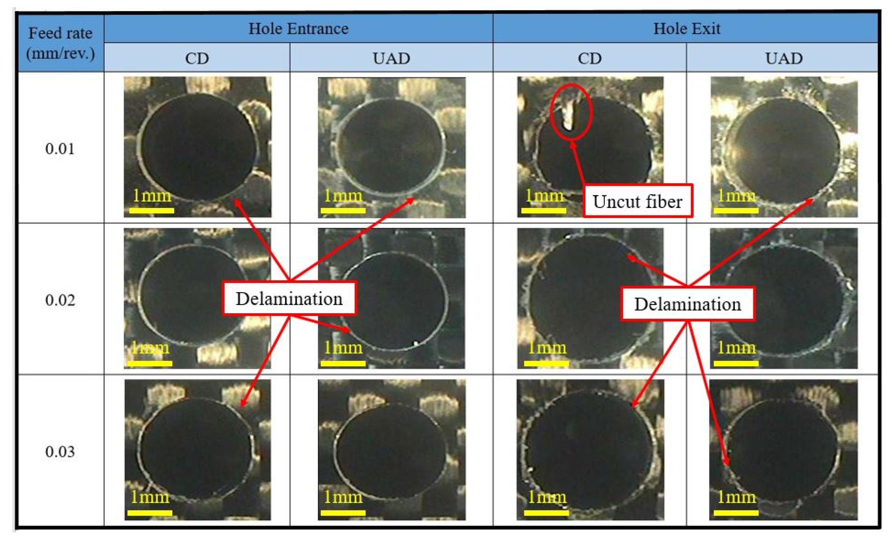
The delamination of exit holes may be better than the delamination at the entrance. However, in CD, the burrs and tears are monitored because of the pull of phenomena. UAD decreases the tears and burrs because UAD decreases the pull-out phenomena by intermediate vibration motions. UAD reduces the CFRP fraying that is a common defect from drilling CFRPs by CD because of the brittle nature of the CFRP material. Figure 6 shows the same concept for 3000 rpm. It was noticed that the UAD succeeded in minimizing the peel-up defect because of the ultrasonic high frequency for the hole entry. Moreover, UAD caused intermittent cutting, which reduced the heat and mechanical stress, subsequently, enhancing the integrity of the cutting edge. For the hole exit, UAD decreased push-out delamination and also reduced the fiber splintering. Figure 7 shows the effect of various feed rates on CD and UAD with 5000 rpm. For the exit hole, it was noticed that the type of uncut fibers affected the quality of the hole exit in CD. UAD eliminated the uncut fiber, hence the tears were decreased. Generally, UAD typically succeeded in enhancing CFRP machining by reducing the thermal damage and other defects.
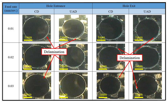
Figure 6.
Morphology of the hole entrance and exit at 3000 rpm.

Figure 7.
Morphology of the hole entrance and exit at 5000 rpm.
Figure 8a describes the delamination factor defect produced from drilling the CFRP using the CD and UAD methods for feed rates ranging from 0.01 to 0.03 mm/rev with various spindle speeds. It was observed that a high delamination factor occurred for the 0.03 mm/rev feed rate at 5000 rpm for CD, with a value of about 1.08. This can be explained by the high value of the linear speed for the given parameters. The best result was shown by 0.02 mm/rev and 3000 rpm because of the ability to integrate with high frequency. UAD could lower the delamination factor across all feed rates by improving fiber cutting. High feed rates increased the delamination factor in both methods, however, UAD decreased the delamination factor compared with CD. Monitoring the delamination columns for the entrance of different spindle speeds and feed rates revealed that the ultrasonic assisting vibration (UAD) decreased the delamination factor because UAD can improve the performance by evacuating debris and improving intermediate vibration cutting. At conditions of 0.02 mm/rev with 3000 rpm support, the lowest delamination factor with an average 1.027 could reach 1.004, which means the delamination factor for the purpose condition could ≃ 1, a perfect result.
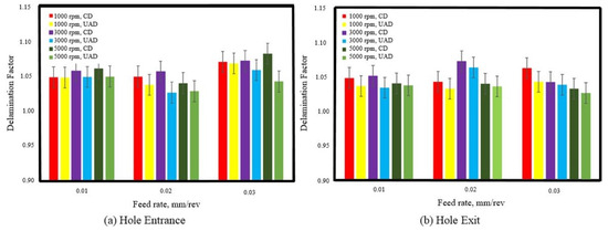
Figure 8.
Comparison of the delamination factor for CD and UAD (a) at the hole entrance; (b) at the hole exit.
Figure 8b shows the effect of various feed rates on the delamination factor across all spindle speeds for the holes’ exit. It was demonstrated that UAD enhanced the performance of the drilling because of its ability to evacuate the debris and the nature of vibration, which converts the continuous cut into intermittent cutting paths that develop the cutting, and the reciprocating motion increases the cutting performance.
3.2. Scanning Electron Microscopy (SEM)
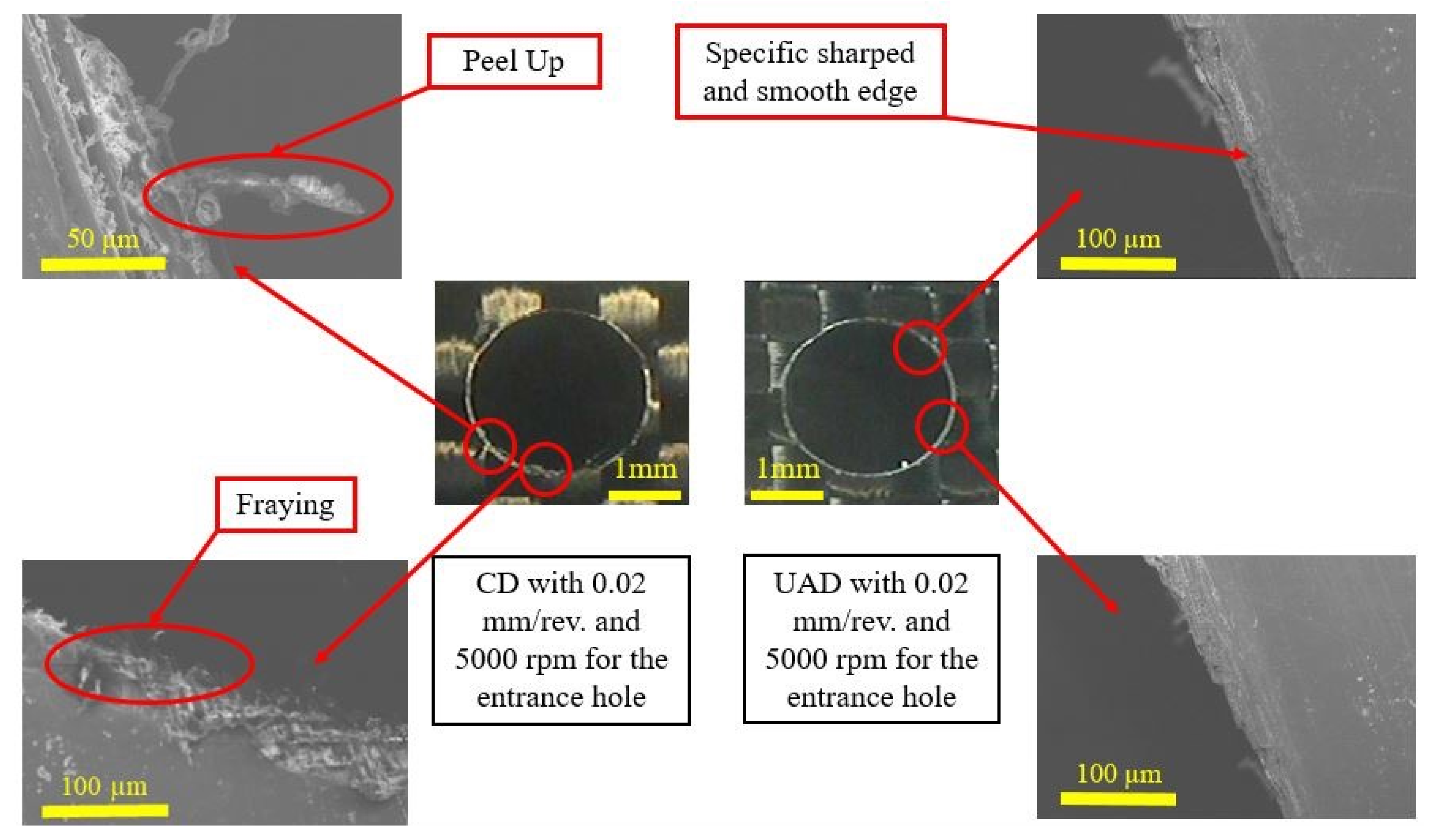
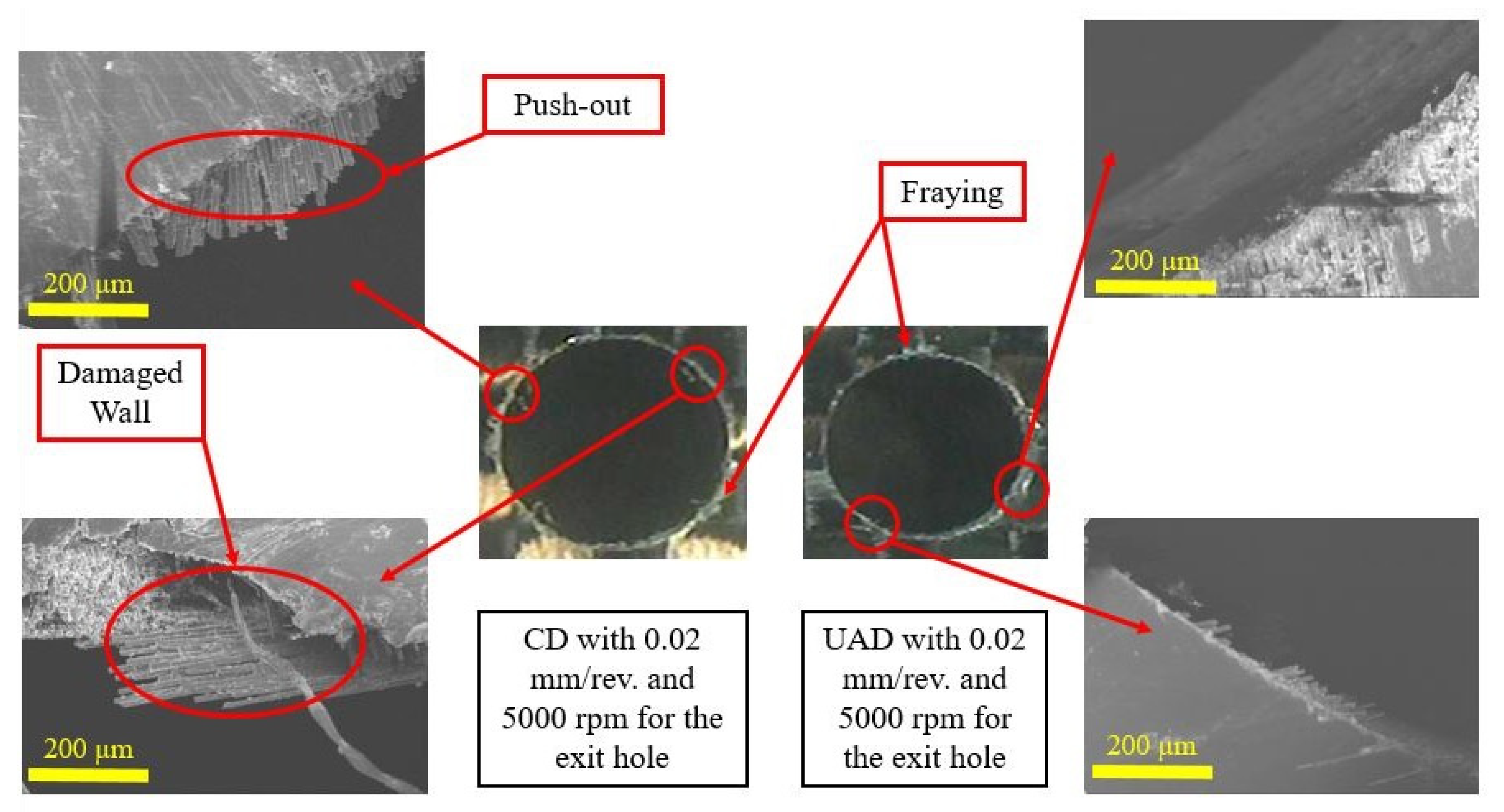
Figure 9 provides an SEM image for comparing the hole entrance quality in CFRP drilling using CD and UAD, with 5000 rpm as the spindle speed and 0.02 mm/rev as the feed rate. It was observed that in the case of CD, a fiber pull-out defect appeared at the hole edges. Debris accumulated around the periphery of the fractured matrix material. Moreover, the cutting efficiency was poor for fiber, and the fraying defect also appeared clearly in the hole edge, whereas UAD exhibited a sharper edge and presented more resin distribution along the edge. UAD has the potential to minimize the pull-out defect. UAD helped minimize the fraying defect and almost sharpened the hole’s edge. Figure 10 shows the SEM image for the drilled hole exit by CD and UAD with the same parameters of 0.02 mm/rev and 5000 rpm. The figure shows the difference between the two holes’ exit through circularity, circularity, edge chipping, or burr formation. UAD could reduce the burrs and improved the surface finish due to ultrasonic vibrations. CD produced rough edges and fiber tearing whereas UAD supported smoother edges, reduced burrs, and created better precision. CD produced large burrs in the hole exit because the twist drill broke through the materials, and pushed and deformed the last uncut layer, producing the push-out delamination defect, which is a common defect for the CD of CFRPs; however, UAD produced a specific clear edge compared with CD. CD damaged the hole wall because of the high friction and the CFRP’s low thermal conductivity, which focused the heat in the machining region of the CFRP. Therefore, UAD can minimize the burr height and support smooth and sharp edges besides offering a uniform hole wall without scratches.

Figure 9.
SEM images of fiber damage at the hole entrance during CD and UAD.
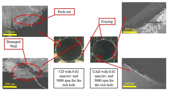
Figure 10.
SEM images of fiber damage at the hole exit during CD and UAD.
Figure 9 and Figure 10 show the identical hole entry and exit parameters for purposes of comparison. It is clear, without any doubt, that UAD supports a superior performance over CD for hole entry and exit quality due to its high ultrasonic vibration with high high-frequency that prevents tears.
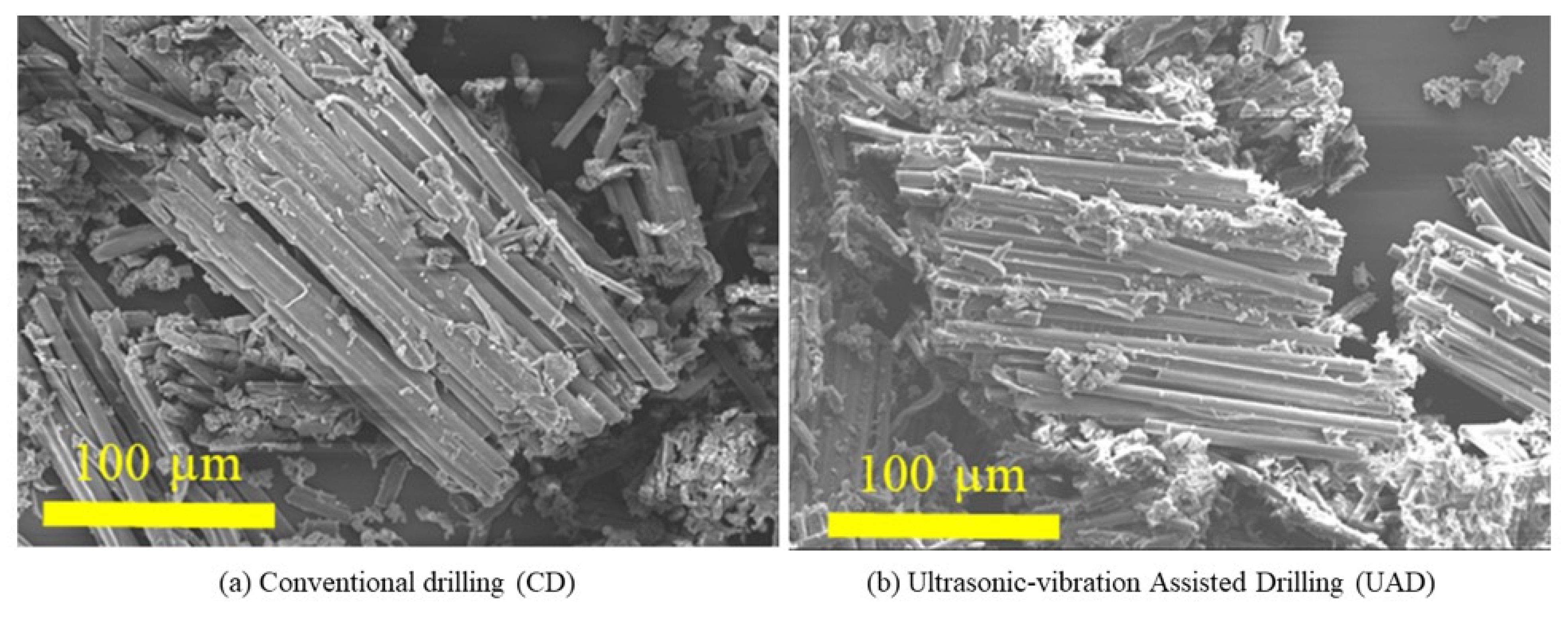
Figure 11 shows the burr terminology with conditions of 0.02 mm/rev 5000 rpm for CD and UAD. CD produced large and jagged burrs with fiber pull-out and resin debris whereas UAD supported smaller and more uniform burrs with minimal fiber fraying and smoother edges. The nature of CD produces continuous cutting, which generates high friction and subsequently high heat, causing high fracture rates for brittle fibers, whereas UAD supports ultrasonic vibration, which causes intermittent cutting, thus reducing the vibration and generated heat. UAD’s high-frequency vibrations are critical for minimizing burrs and fiber damage in CFRP drilling, especially at high spindle speeds. CD requires auxiliary measures (cooling, optimized tools) to match UAD’s performance.

Figure 11.
Burr morphology: (a) CD; (b) UAD.
3.3. Surface Roughness
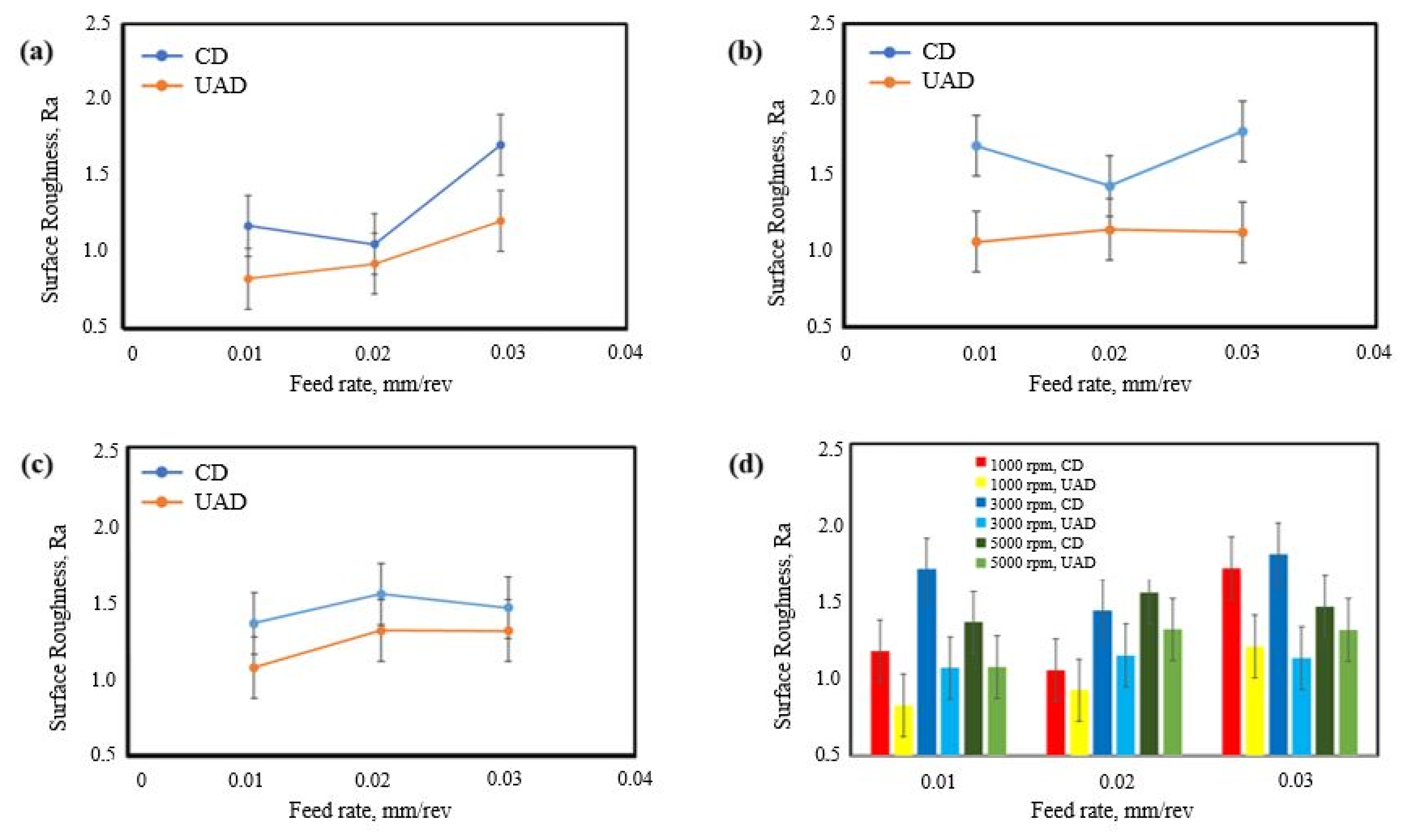
Figure 12 shows the relationship between the item surface roughness produced by CD and UAD and the applied feed rate with 1000, 3000, and 5000 rpm as the spindle speeds. The figure aims to show the effect of surface roughness produced from UAD separately to identify the effect for each spindle speed. In Figure 12a, the surface roughness was increased with an increase in the feed rate. It can be seen that UAD supported a better surface quality compared with the surface roughness resulting from CD; especially at a low feed rate of 0.01 mm/rev, UAD created a smoother surface finish under the same conditions compared with CD. UAD also supported high effectiveness at higher speed feed rates. UAD enhanced the chip evacuation through the radial vibration created, whereas CD, with its behavior of continuous path, increased the created roughness. In Figure 12b, and c for 300 rpm and 5000 rpm respectively, the curves showed the same concept as the previous curve for 1000 rpm. For 3000 rpm, the surface roughness was also increased with an increase in the feed rate. This occurred because the high feed rate increases the interaction of the workpiece with the cutting tool, which creates more side vibrations and a low surface quality. At a feed rate of 0.02 mm/rev and 1000 rpm, UAD’s surface roughness was about 0.8 µm, with the possibility of reaching 0.5 µm with error bars analysis, so is suitable for precision applications, while the CD’s surface roughness was about 1.2 µm then the UAD with an enhanced percentage of about 20%. UAD is more qualified because the UAD method creates vibration with a high frequency that decreases the friction, improving the chip evacuation and minimizing the side tool vibration.
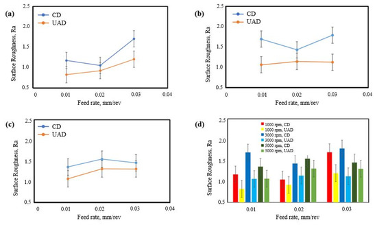
Figure 12.
Effect of feed rate with CD and UAD on the resulting surface roughness through different spindle speeds: (a) 1000 rpm, (b) 3000 rpm, (c) 5000 rpm, and (d) comparison for all speeds.
Figure 12d shows the effect of the feed rate on the surface roughness across all spindle speeds. Generally, the surface roughness increased with an increase in the feed rate for all spindle speeds under the same conditions for CD and UAD. UAD produced smoother surface roughness compared with CD. The best value for the surface roughness was at 0.01 mm/rev and 1000 rpm, whereas the worst result was with 0.03 mm/rev and 3000 rpm with an average of 1.75 µm and could reach 2.3 µm.
3.4. Cutting Forces
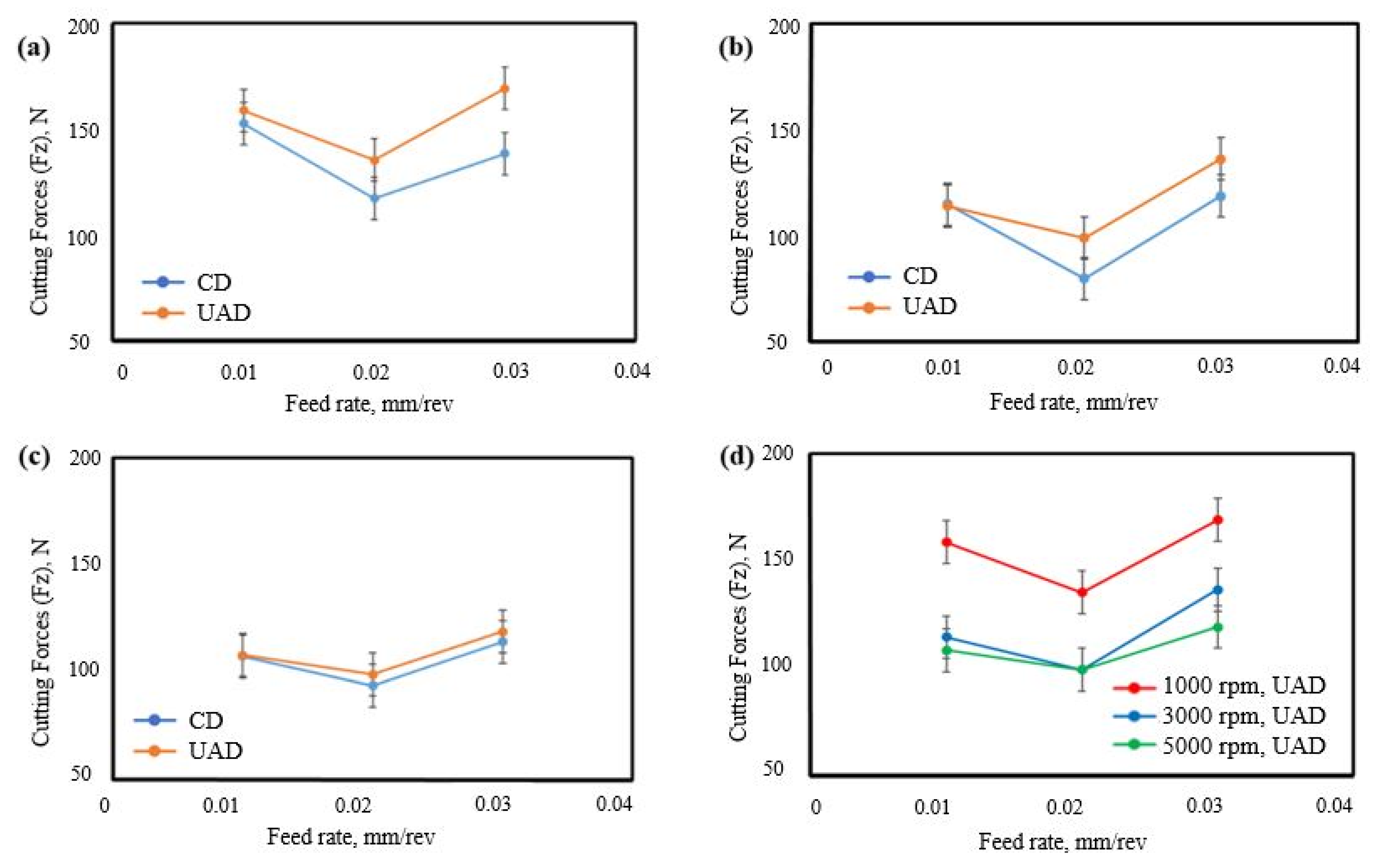
Figure 13 shows the relationship between the feed rate and the cutting forces for 1000, 3000, and 5000 rpm for CD and UAD. It can be seen that the cutting forces were higher in the case of UAD compared with CD in all conditions, except for several conditions, such as 0.01 mm/rev as the feed rate for 3000, 5000, and even 1000 rpm, where the difference was not big. CFRPs consist of a layered material with reinforced carbon and a polymer as a resin. Carbon is a brittle material, whereas the fiber is soft. The high frequency generated from UAD causes intermittent cutting, which creates micro impacts on the fibers, causing more fractures per time. Furthermore, the fragmented chips increase the friction between the tool and workpiece, so UAD increases the cutting force to overcome this problem. However, the low amplitude with high frequency used in the experiments decreased the cutting forces of UAD and made the difference very low with CD.

Figure 13.
Effect of the feed rate with UAD and CD on the cutting forces through different spindle speeds: (a) 1000 rpm, (b) 3000 rpm, (c) 5000 rpm, and (d) UAD cutting forces.
It is necessary to obtain the best cutting force for UAD. Although UAD does not support enhancing the cutting forces compared with CD, UAD supports excellent results for surface quality and morphology of the hole entrance and exit, which is strongly recommended for special applications. Figure 13d shows the relationship between the cutting force and feed rate during UAD only. The trend of the curve showed that the cutting forces increased with increasing feed rates. Higher feed rates require more material removed per revolution, which increases the interaction between the cutting tool and the workpiece. It was observed that the low cutting speed offers high cutting forces, and 5000 rpm supports low cutting forces because faster speeds improve the shear efficiency and reduce heat buildup.
Subsequently, the cutting force results can be summarized as follows. At a minimum feed rate of 0.01 mm/rev for UAD vs. CD, it was found that near-identical forces varied from 0 to 4% for 1000, 3000, and 5000 rpm, as shown in Figure 13a–c. This can be explained by the minimal material removal per cycle, which may render the vibration effects negligible. However, at a high feed rate of 0.03 mm/rev, UAD showed 8–12% higher forces because the increased material removal per cycle amplified UAD’s micro impacts, thereby increasing the cutting forces. This was confirmed by the SEM fiber fractures, as shown in Figure 11. At a spindle speed of 3000 rpm with a feed rate of 0.01 mm/rev, an optimal balance was achieved as the UAD cutting forces matched those of the CD cutting forces, as shown in Figure 13b, due to resonance enhancing chip evacuation and reducing friction. At a spindle speed of 5000 rpm, UAD cutting forces increased by 10% due to vibration damping at extreme speeds.
4. Conclusions
CFRPs play a significant role in industry due to their exceptional properties. However, the drilling of CFRPs causes several defects including delamination, fiber pull-out, and tears. Wet drilling is vital to minimize these defects. However, the costs are very high and require extra power and a cycling system, which also increases the cost of the final products. This study compared hybrid ultrasonic-assisted drilling (UAD) with conventional drilling (CD) at spindle speeds below 5000 rpm and varying feed rates. The analysis focused on hole quality, delamination factor, cutting forces, and chip morphology using SEM. UAD significantly enhanced the CFRP hole quality (morphology, roughness) despite slightly higher cutting forces. Regarding the trade-offs, UAD can raise the cutting forces under some conditions; however, it significantly improves the surface quality and enhances the hole entrance and exit morphology by reducing the delamination factor. The current work can be summarized in the following points:
UAD reduced the delamination factor compared with CD. UAD, with optimum condition at conditions of 0.02 mm/rev and 3000 rpm, supported the lowest delamination factor with an average of 1.027 and could reach 1.004, that is, ≃1.
From the SEM images, UAD minimized pull-out defects, fraying, and burrs for hole entry and exit compared with CD in the dry condition.
At 1000 rpm and 0.02 mm/rev, the UAD created the optimum surface quality that could reached at 0.5 µm with an enhanced percentage of about 50%.
There was a delamination reduction to K = 1.004–1.027 compared with CD’s 1.08 at 3000 rpm/0.02 mm/rev.
The increase in feed rate increased the surface roughness and cutting forces.
UAD almost maintained the cutting forces equal to the cutting forces in CD, with a small increase in some cases.
UAD minimized the increase in cutting forces, making them nearly equivalent to conventional drilling, at a feed rate of 0.01 mm/rev and 3000 rpm.
UAD showed burr height minimization to 12 ± 0.6 µm compared with CD’s 35 ± 1.2 µm.
These quantitative gains validate UAD’s industrial potential for precision CFRP machining without lubricants.
Author Contributions
Conceptualization, K.H.; Methodology, K.H.; Validation, S.A.; Formal analysis, S.A.; Investigation, K.H.; Resources, S.A.; Writing—original draft, K.H.; Writing—review & editing, S.A.; Visualization, K.H.; Supervision, K.H. All authors have read and agreed to the published version of the manuscript.
Funding
This research received no external funding.
Data Availability Statement
The original contributions presented in this study are included in the article. Further inquiries can be directed to the corresponding author.
Conflicts of Interest
The authors declare no conflict of interest.
References
- Abish, J.; Samal, P.; Narenther, M.S.; Kannan, C.; Balan, A.S.S. Assessment of drilling-induced damage in CFRP under chilled air environment. Mater. Manuf. Process. 2018, 33, 1361–1368. [Google Scholar] [CrossRef]
- Jia, Z.; Fu, R.; Niu, B.; Qian, B.; Bai, Y.; Wang, F. Novel drill structure for damage reduction in drilling CFRP composites. Int. J. Mach. Tools Manuf. 2016, 110, 55–65. [Google Scholar] [CrossRef]
- Xu, J.; Yin, Y.; Davim, J.P.; Li, L.; Ji, M.; Geier, N.; Chen, M. A critical review addressing drilling-induced damage of CFRP composites. Compos. Struct. 2022, 294, 115594. [Google Scholar] [CrossRef]
- Zhu, W.; Fu, H.; Li, F.; Ji, X.; Li, Y.; Bai, F. Optimization of CFRP drilling process: A review. Int. J. Adv. Manuf. Technol. 2022, 123, 1403–1432. [Google Scholar] [CrossRef]
- Song, Y.; Cao, H.; Zheng, W.; Qu, D.; Liu, L.; Yan, C. Cutting force modeling of machining carbon fiber reinforced polymer (CFRP) composites: A review. Compos. Struct. 2022, 299, 116096. [Google Scholar] [CrossRef]
- Shao, Z.; Jiang, X.; Geng, D.; Liu, Y.; Zhou, Z.; Li, S.; Zhang, D.; Zheng, W. The interface temperature and its influence on surface integrity in ultrasonic-assisted drilling of CFRP/Ti stacks. Compos. Struct. 2021, 266, 113803. [Google Scholar] [CrossRef]
- Soutis, C. Carbon fiber reinforced plastics in aircraft construction. Mater. Sci. Eng. A 2005, 412, 171–176. [Google Scholar] [CrossRef]
- Eneyew, E.D.; Ramulu, M. Experimental study of surface quality and damage when drilling unidirectional CFRP composites. J. Mater. Res. Technol. 2014, 3, 354–362. [Google Scholar] [CrossRef]
- Anand, R.S.; Patra, K. Mechanistic cutting force modelling for micro-drilling of CFRP composite laminates. CIRP J. Manuf. Sci. Technol. 2017, 16, 55–63. [Google Scholar] [CrossRef]
- Raj Kumar, D.; Jeyaprakash, N.; Yang, C.H.; Ramkumar, K.R. Investigation on Drilling Behavior of CFRP Composites Using Optimization Technique. Arab. J. Sci. Eng. 2020, 45, 8999–9014. [Google Scholar] [CrossRef]
- Grigoriev, S.N.; Fedorov, S.V.; Hamdy, K. Materials, properties, manufacturing methods and cutting performance of innovative ceramic cutting tools—A review. Manuf. Rev. 2019, 6, 19. [Google Scholar] [CrossRef]
- Cong, W.; Feng, Q.; Pei, Z.; Deines, T.; Treadwell, C. Rotary ultrasonic machining of carbon fiber-reinforced plastic composites: Using cutting fluid vs. cold air as coolant. J. Compos. Mater. 2012, 46, 1745–1753. [Google Scholar] [CrossRef]
- Wang, F.-j.; Cheng, D.; Zhang, B.-y.; Yan, J.-b.; Ma, J.-w.; Wang, Z.-g.; Wang, S.-f. Reversed-Air Cooling Technology for High-Quality Drilling of CFRP. Appl. Compos. Mater. 2019, 26, 857–870. [Google Scholar] [CrossRef]
- Gupta, A.; Ascroft, H.; Barnes, S. Effect of Chisel Edge in Ultrasonic Assisted Drilling of Carbon Fibre Reinforced Plastics (CFRP). Procedia CIRP 2016, 46, 619–622. [Google Scholar] [CrossRef]
- Isbilir, O.; Ghassemieh, E. Comparative Study of Tool Life and Hole Quality In Drilling of CFRP/Titanium Stack Using Coated Carbide Drill. Mach. Sci. Technol. 2013, 17, 380–409. [Google Scholar] [CrossRef]
- Xu, J.; Li, C.; Chen, M.; El Mansori, M.; Ren, F. An investigation of drilling high-strength CFRP composites using specialized drills. Int. J. Adv. Manuf. Technol. 2019, 103, 3425–3442. [Google Scholar] [CrossRef]
- Shao, Z.; Jiang, X.; Li, Z.; Geng, D.; Li, S.; Zhang, D. Feasibility study on ultrasonic-assisted drilling of CFRP/Ti stacks by single-shot under dry condition. Int. J. Adv. Manuf. Technol. 2019, 105, 1259–1273. [Google Scholar] [CrossRef]
- Huang, W.; Cao, S.; Li, H.N.; Zhou, Q.; Wu, C.; Zhu, D.; Zhuang, K. Tool wear in ultrasonic vibration–assisted drilling of CFRP: A comparison with conventional drilling. Int. J. Adv. Manuf. Technol. 2021, 115, 1809–1820. [Google Scholar] [CrossRef]
- Lotfi, M.; Akbari, J. Finite element simulation of ultrasonic-assisted machining: A review. Int. J. Adv. Manuf. Technol. 2021, 116, 2777–2796. [Google Scholar] [CrossRef]
- Kurniawan, R.; Chen, S.; Xu, M.; Teng, H.; Chen, J.; Ali, S.; Han, P.-W.; Kiswanto, G.; Kumaran, S.T.; Ko, T.J. Understanding the mechanism of ultrasonic vibration-assisted drilling (UVAD) for micro-hole formation on silicon wafers using numerical and analytical techniques. Int. J. Adv. Manuf. Technol. 2024, 132, 1283–1313. [Google Scholar] [CrossRef]
- Xu, M.; Chen, S.; Kurniawan, R.; Li, C.; Kwak, Y.I.; Ali, S.; Choo, M.K.; Han, P.-W.; Ko, T.J. Enhancement of Machinability Study in Longitudinal Ultrasonic Vibration-assisted Milling Inconel 718 Using High-frequency-vibration Spindle. Int. J. Adv. Manuf. Technol. 2023, 126, 3523–3542. [Google Scholar] [CrossRef]
- Krishnaraj, V.; Prabukarthi, A.; Ramanathan, A.; Elanghovan, N.; Kumar, M.S.; Zitoune, R.; Davim, J.P. Optimization of machining parameters at high speed drilling of carbon fiber reinforced plastic (CFRP) laminates. Compos. Part B Eng. 2012, 43, 1791–1799. [Google Scholar] [CrossRef]
- Park, K.-H.; Beal, A.; Kim, D.-W.; Kwon, P.; Lantrip, J. A Comparative Study of Carbide Tools in Drilling of CFRP and CFRP-Ti Stacks. J. Manuf. Sci. Eng. 2014, 136, 014501. [Google Scholar] [CrossRef]
- Xu, M.; Cao, L.; Li, J.; Ali, S.; Kurniawan, R.; Li, C.; Yu, L.; Chen, S.; Ko, T.J. Experimental, modeling, and numerical simulation of ultrasonic assisted drilling of CFRP/Ti stacks. J. Manuf. Process. 2025, 133, 97–117. [Google Scholar] [CrossRef]
- Li, P.; Sun, J.; Li, J.; Zhang, R.; Chen, G. Study on drilling force and export defects of CFRP composites in RULTVD. J. Manuf. Proc. 2025, 134, 880–890. [Google Scholar] [CrossRef]
- Dong, S.; Zheng, K.; Zhang, W. Investigation on cutting temperature of CFRP in robotic rotary ultrasonic drilling with minimum quantity lubrication. J. Adv. Manuf. Sci. Technol. 2025, 5, 2025001. [Google Scholar] [CrossRef]
- Xu, P.; Yin, J.; Zhao, M.; Su, H.; Xu, J. Performance of high-frequency ultrasonic vibration-assisted drilling of ceramic matrix composites. J. Manuf. Process. 2025, 133, 86–96. [Google Scholar] [CrossRef]
- Hu, C.; Han, S.; Chen, M.; Zhu, Y. Experiment analysis on defects in ultrasonic-assisted drilling of carbon fiber reinforced plastic with different diameter drills. Compos. Adv. Mater. 2024, 33, 1–14. [Google Scholar] [CrossRef]
- Ji, P.; Wang, C. Research on drilling method for carbon fiber-reinforced plastic based on ultrasonic vibration-assisted drilling. Int. J. Adv. Manuf. Technol. 2025, 137, 5321–5337. [Google Scholar] [CrossRef]
- Waseem, M.; Hanif, M.W.; Jawad, M.; Hussain, S. Evaluating the effect of cryogenic cooling in reducing the delamination during drilling of carbon fiber reinforced plastic (CFRP) and Al 2024 stack. Int. J. Interact. Des. Manuf. 2025. [CrossRef]
- Grigoriev, S.N.; Okunkova, A.A.; Volosova, M.A.; Hamdy, K.; Metel, A.S. Electrical Discharge Machining of Al2O3 Using Copper Tape and TiO2 Powder-Mixed Water Medium. Technologies 2022, 10, 116. [Google Scholar] [CrossRef]


Disclaimer/Publisher’s Note: The statements, opinions and data contained in all publications are solely those of the individual author(s) and contributor(s) and not of MDPI and/or the editor(s). MDPI and/or the editor(s) disclaim responsibility for any injury to people or property resulting from any ideas, methods, instructions or products referred to in the content. |
© 2025 by the authors. Licensee MDPI, Basel, Switzerland. This article is an open access article distributed under the terms and conditions of the Creative Commons Attribution (CC BY) license (https://creativecommons.org/licenses/by/4.0/).