Abstract
The interference fit is a common process for the assembly of mechanical parts on a shaft for diverse mechanical engineering applications. One of the manufacturing methods consists of introducing a shaft into a hub by applying a force being the hub diameter lower than the shaft diameter. This way, contact pressure is generated at the shaft–hub interface at the end of the process, enabling torque transmission. Thus, a non-uniformly distributed stress state appears at the shaft–hub interface with significant stress peaks at the hub edges. In addition, as a consequence of the manufacturing process, local plasticity is generated in the hub on the insertion side causing changes in stress distributions. In this paper, an analysis based on finite elements simulations is carried out to reveal the influence of, on one hand, manufacturing parameters such as friction on stress concentrations at the interface and, on the other hand, geometrical parameters such as hub chamfer angle, considering chamfer hubs and conventional hubs. To achieve this goal, different simulations of the mechanical manufacturing process of the axial assembly of press fits are carried out to reveal the stress fields at the interface. Thus, stress concentrations under different friction conditions from a case without friction to a dry friction case are revealed and analyzed. The results show, on one hand, the friction coefficient as a highly influential factor, causing asymmetrical stress distributions with high stress concentrations that reduce the mechanical performance of press fits and, on the other hand, the beneficial impact of chamfer hubs for lowering stress concentrations.
1. Introduction
A widely used method for the assembly of mechanical parts consists of the axial insertion of a shaft, with an oversized diameter, into a hub, with an undersized diameter, resulting in the so-called press fits. Hub is the common term for referring to multiple mechanical components, such as pulleys, gears, wheels, bearings, etc. [1,2,3,4]. The force applied to the shaft during the assembly of a press fit is dependent on the contact pressure at the interface and on the shaft and hub friction coefficient [5,6,7,8,9]. In addition, friction is also an influencing parameter on the maximum transmitted torque of the assembled fit [2,10,11,12,13]. Friction is a complex phenomenon that is affected by multiple factors, such as the type of materials [14,15], surface roughness [16,17], type of lubrication, etc. At the end of the press fit assembly, a stress field appears at the shaft–hub interface due to the different diameters of the hub and shaft, resulting in contact pressure at the interface. Equations derived from the thick-walled pressure cylinder theory considering the same length for the shaft and hub are used for the design of interference fits, allowing the estimation of the resulting stress state. According to these equations, the radial, tangential, and von Mises stresses are uniformly distributed at the shaft–hub interface [18,19,20,21]. In addition, the axial stress is considered negligible. However, the estimation given by theoretical equations is not realistic since high stress concentrations (SCs) appear at the hub edges [22,23,24,25,26,27] due to the fact that, in practice, the length of the shaft exceeds the length of the hub. Furthermore, the design equations for press fits do not consider the manufacturing-induced plastic strains caused by inserting the shaft axially into the hub [28,29,30,31] and, in addition, such equations do not take into account the role of friction in stress distributions [32]. This way, manufacturing-induced localized plastic strains can modify stress distributions at the interface causing a reduction in the contact pressure or even zones without contact between the hub and shaft. Consequently, the existence of both SC and plastic strains can affect the mechanical performance of the interference fit. As a result, non-desirable phenomena such as vibrations [33], fretting fatigue [34,35,36,37,38,39], or fretting wear [40,41,42,43] can appear, leading to crack initiation and growth [44,45,46,47,48] and causing the final failure of these mechanical components.
Therefore, the assembly process of press fits produces a non-uniformly distributed stress at the shaft–hub interface with high SCs at the hub edges that are not considered in design equations. Different design methods were developed with the aim of relieving such SCs, mainly consisting of geometrical modifications [49] of the hub. Thus, simple geometries such as round grooved hubs [50,51], chamfer hubs [52,53], or contact pressure rings [54] are commonly used for this purpose. However, more complex modifications are also considered, such as hubs with an exponential variated thickness in the radial direction [55], hubs with a variable radial interference [53], or functionally graded materials [56,57]. Commonly the SCs located at the hub edges of press fits are determined by finite element method (FEM) numerical simulations [14,40,58,59,60,61] since the stress state estimation at the hub–shaft interface shows serious difficulties.
In a previous study [32], the influence of friction on the contact pressure at the interface was analyzed for conventional and chamfer hubs. The results obtained revealed that the friction coefficient is a key factor that notably modifies the contact pressure (opposite to radial stress) at the shaft–hub interface. However, the analysis was limited to radial stress, and no additional information about tangential, axial, or von Mises stresses or stress concentration factors (SCFs) was revealed in such a study. In addition, the beneficial effect of chamfer hubs was revealed in [52] without considering the manufacturing-induced effects in terms of plastic strains on stress distributions. This study tries to fill this gap by analyzing the effects of manufacturing-induced plastic strains and friction on stress states and, from them, to provide an estimation of the SCFs that can be useful for designing press fits.
This way, taking into account the influence of both friction and hub geometry on SCs in a press fit, it is relevant to analyze the effects of such factors on manufacturing-induced stress fields at the shaft–hub interface of a press fit considering different friction conditions and diverse hub geometries. Thus, SCs could be quantified, and, hence, a more accurate estimation of the stress fields could be considered for designing press fits for both conventional and optimized hub geometries. This way, the aim of this study is to analyze the effects of friction on SCs at the shaft–hub interface of a press fit while considering the manufacturing-induced friction effects in conventional and optimized chamfer hubs. To achieve this goal, different numerical simulations of the press fit assembly were simulated by FEM to reveal the stress field while considering different chamfer hub geometries and friction conditions.
2. Materials and Methods
Classical thick-walled cylinder theory [10,18] provides different equations used in press fit design for estimating contact pressure (p), assuming identical materials for shaft and hub:
where E represents the Young modulus, δ denotes the radial interference, R is the radius at the shaft–hub interface, and ro is the outer radius of the hub.
The contact pressure induces stress distribution within the shaft and the hub. Based on the theory, (i) radial stress is the negative of contact pressure, (ii) the axial stress is null, and (iii) the tangential stress is defined by [10,18]:
This way, the von Mises stress can be obtained by the following expression:
These equations are derived based on two key assumptions: (i) the axial lengths of the shaft and the hub are identical, and (ii) the plane strain condition of elasticity theory is applicable. The maximum transmittable torque (T) is expressed as a function of the friction coefficient (μ), the contact pressure (p), and the hub’s geometry: hub length, L and radius at the hub–shaft interface, R [10,18], as follows:
Finite Elements Numerical Modeling
The 40H7/s6 hard press fit, as defined by the ISO standard [62], is appropriate for applications needing torque transmission and rotational connection between a shaft and hub. This study utilizes dimensions from prior research [32], with the same hub length as the shaft diameter (L/d = 1) and a shaft length twice the hub length (l/L = 2). Specifically, the reference case includes a solid shaft (R = 20 mm, l = 80 mm) and a hollow hub (L = 40 mm, ro = 40 mm). Based on the interference fit tolerances, the maximum radial interference for a 40H7s6 interference fit is 29.5 μm.
A simple geometric variation in a conventional hub is the so-called chamfer hub, where a chamfer is introduced at the hub edges. For characterizing such a geometry, a single additional parameter is needed, the chamfer angle, α. This angle is determined by the ratio of the axial chamfer length, lz, to the hub thickness, t, (Figure 1), expressed as α = arctan(lz/t). The limit case, where lz equals half the interface length, yields the maximum chamfer angle, αmax = arctan(L/2t). For this analysis, a range of chamfer angles was investigated, spanning from 0° (representing a standard hub) to 20°, with specific values of 5°, 7°, 9°, 10°, 12°, 15°, 17°, and 20°. Chamfer angles exceeding 20° were not considered due to practical limitations in upper hub width. To isolate the effects of chamfer angle on contact pressure, a constant contact hub length, L, is considered for all cases of the study.
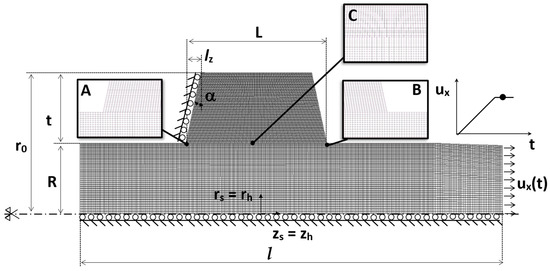
Figure 1.
Four-node quadrilateral element mesh used in simulations identifying the dimensions and boundary conditions applied showing the detailed views of insertion hub edge A, the exit hub edge B and the midpoint of interface C.
For the shaft and hub components, AISI 1080 steel was selected, with material properties defined as follows: Young modulus, E = 200 GPa; Poisson ratio, ν = 0.29; and yield strength, σY = 585 MPa. The material’s constitutive behavior was modeled as elastoplastic, incorporating the J2 yield criterion for accurate stress predictions. To leverage the revolute symmetry of the shaft–hub assembly, an axisymmetric finite elements (FE) model was developed, significantly reducing computational demands. Boundary conditions were implemented to constrain radial displacements along the shaft’s central axis and axial displacements at the hub’s insertion-side edge (Figure 1).
Two distinct simulation approaches were considered: static and dynamic. In the static analysis, radial interference was introduced using a specific function included in the MSC.Marc 2023 FE software, for simulating the resulting stress distributions. The dynamic approach simulates the press fit assembly process by applying a linear time-dependent displacement (u(t)) to the shaft’s insertion point that forces the shaft to pass into the hub. To ease shaft insertion, a 7% conical chamfer was included at the hub’s entry. Coulomb friction was modeled at the contact interface, and diverse friction coefficients were considered to reveal the influence of such factors on stress distributions.
A four-node quadrilateral elements mesh was generated for both components, with mesh refinement strategically concentrated at the shaft–hub interface to enhance accuracy in critical regions while minimizing computational cost. To ensure solution convergence, a mesh refinement study was performed utilizing a mesh factor, Km, defined as the ratio of the current mesh’s element count to that of a base mesh. The element density was systematically increased by doubling the number of elements (Km = 1, 2, 4, 8, 16).
Validation of the numerical results was conducted by comparing radial stress values at point C, the midpoint of the shaft–hub interface (Figure 1), with theoretical predictions derived from Equation (1). The relationship between radial stress, relative error, ε, and the Km is visualized in Figure 2. Based on this analysis, a mesh consisting of 4900 elements (5187 nodes) was chosen for static simulations, resulting in a relative error (ε) of approximately 5%. For dynamic simulations, a mesh of 4736 elements (4958 nodes) was deemed sufficient; it also yielded a relative error (ε) of approximately 5%. The element dimensions at the contact interface were maintained at 0.8 mm × 0.8 mm for both mesh configurations.
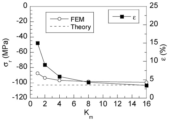
Figure 2.
FE convergence testing and estimated error for dynamic FE simulations at point C placed in the middle of the shaft–hub interface.
3. Results
The manufacturing process of press fits generates plasticity at hub edge A, as was analyzed in previous studies [32]. This way, for achieving reliable results, the stress analysis obtained by the press fit assembly FEM simulation must consider the elastoplastic behavior of both the hub and shaft materials. Thus, for a better understanding of the stress distributions appearing in the interface of a press fit, different approaches are considered, as follows: (i) the theoretical stress uniformly distributed throughout the shaft–hub interface; the numerical FE simulations of (ii) the static case, considering the hub and shaft already assembled, i.e., without manufacturing effects; and two dynamic cases where the press fit manufacturing process is simulated, considering (iii) the linear elastic materials behavior, ignoring plasticity effects, and (iv) the dynamic case where the elastoplastic materials behavior is considered, revealing the effect of manufacturing-induced plasticity on stress distributions. Friction was omitted from all the simulations, as its influence on the stress fields is addressed in Section 3.2.
3.1. Shaft–Hub Interface Stress Distributions
Figure 3 shows the shaft–hub interface stress distributions after the assembly process considering a conventional hub without friction. According to the obtained results, the hub stress distributions comprise three different zones: (i) the insertion zone where a huge SC is located, (ii) the middle zone where the stress distributions are similar to those predicted by theory, and (iii) the exit zone of the shaft where a high stress appears. This way, in Figure 3a, Figure 3b, Figure 3c, and Figure 3d are shown the radial, tangential axial, and von Mises stress distributions, respectively, for the three different approaches considered in simulations nearby the insertion zone, and Figure 3e, Figure 3f, Figure 3g, and Figure 3h show the same stress distributions at the exit zone of the shaft.
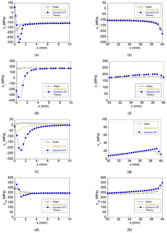
Figure 3.
Shaft–hub interface stress distributions after assembly for different numerical simulation approaches: static, dynamic linear elastic (LE), dynamic elastoplastic (EP); values given by theoretical expressions: (a) radial stress left side (insertion); (b) radial stress right side (opposite to insertion); (c) tangential stress left side; (d) tangential stress right side; (e) axial stress left side; (f) axial stress right side; (g) von Mises stress left side; (h) von Mises stress right side.
Regarding the radial stress, the static case and the dynamic case without considering plasticity predict similar SCs at hub edge A and hub edge B. Nevertheless, when the plastic behavior is considered, key changes are observed. At the insertion hub edge (Figure 3a), the point of maximum radial stress moves to a more internal location on the interface. This maximum radial stress is higher (50%) than that obtained using both the linear elastic approach and the static approach. On the other hub edge (point B), the radial SC (Figure 3e) is slightly higher (10%) than the one obtained with the other approaches, but in this case, the maximum stress value is located at the hub edge.
With regard to tangential stress, a similar effect of plasticity is observed (Figure 3b,f). The linear elastic dynamic and static approaches provide similar distributions with positive values at the insertion zone reaching a minimal value at the hub edge. At the zone close to hub edge B, the stress distributions are similar to the ones observed at the insertion zone. However, significant differences are observed for the elastoplastic dynamic approach. The tangential stress is negative nearby hub edge A, reaching the maximum stress value at inner points for a depth similar to the one obtained in the radial component. At the outside zone B (Figure 3f), the tangential stress is slightly increased with regard to the values given by the other approaches.
According to theory, axial stress should be null. However, a slight tensile axial stress is obtained for the static case that can be considered negligible (Figure 3c,g). In the case of the linear elastic dynamic approach, an asymmetrical distribution is obtained with a high negative axial stress at hub edge A resulting from the shaft’s insertion into the hub. In the dynamic elastoplastic approach, the maximum axial stress of a compressive nature is obtained at inner points close to the insertion hub edge with a value close to zero at the hub surface. The compressive stress values are significantly higher (two times) than the ones obtained with the other approaches. On the opposite side B, the axial stress is similar to the values obtained with the other approaches with a slightly higher value.
Finally, for the von Mises stress (Figure 3d,h), the approaches where the elastoplastic behavior is not considered lead to similar symmetrical distributions reaching equivalent values on both sides of the hub. For both cases, the maximum values are located at the hub edges with low SC. However, the plasticity effect is shown in the distribution corresponding to the elastoplastic dynamic case where the location of the maximum stress shifts towards the inner points of the interface and values equivalent to that given by theory are obtained at inner points of the shaft–hub interface. Finally, the stress distribution at hub edge B (Figure 3h) is similar to the distributions obtained with the static and linear elastic dynamic approaches, reaching a slightly higher value.
To go further in the analysis, the radial, tangential, axial, and von Mises stress fields produced by the manufacturing of a press fit with a chamfer hub (α = 12°), considering both a frictionless case and a case with dry friction (μ = 0.3), are shown in Figure 4. In this manner, the effects of the chamfer angle and friction are qualitatively analyzed. The radial stress field (Figure 4a) shows, on one hand, an asymmetrical distribution of stress with a high SC near hub edge A caused by the local effect of manufacturing-induced plastic strains. On the other hand, the SC at hub edge B is significantly lower, and the stress distributions at the inner points are uniformly distributed at the interface. For the case considering a conventional dry friction coefficient (Figure 4b), significant changes are produced. Firstly, the SC is higher at hub edge A, and it is extended over a wider zone, including deeper points at the interface. However, the more significant change is produced on hub edge B, where the SC is significantly decreased to disappearance. At the mid-points of the interface, the stress field is still uniformly distributed. This way, friction causes a higher opposition to the shaft to be inserted into the hub producing stress redistribution.
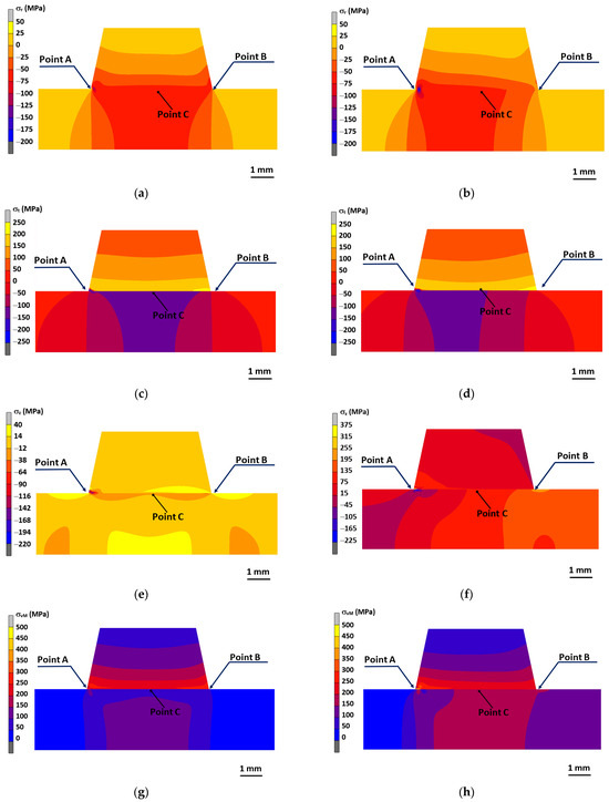
Figure 4.
FE stress distributions in a press fit with a chamfer hub after assembly: (a) radial stress considering frictionless case; (b) radial stress considering friction (μ = 0.3); (c) tangential stress considering frictionless case; (d) tangential stress considering friction (μ = 0.3); (e) axial stress considering frictionless case; (f) axial stress considering friction (μ = 0.3); (g) von Mises stress considering frictionless case; (h) von Mises stress considering friction (μ = 0.3).
Regarding tangential stress (Figure 4c,d), an asymmetrical stress distribution is observed with high negative values located nearby hub edge A, whereas the SC at hub edge B is positive with a slight increment regarding the uniform stress distribution appearing at the midpoints of the interface. The influence of friction on tangential stress is different to the effect previously discussed for radial stress. Thus, on one hand, the stress nearby hub edge A is decreased, and the high stress zone is extended over a wider area; on the other hand, the stress at hub edge B is slightly increased. This way, the stress distribution obtained considering friction is more asymmetrically distributed than that obtained considering the frictionless case.
As previously discussed, theoretical equations do not consider axial stress in a press fit. However, the shaft insertion into the hub causes tensile axial stress at the shaft–hub interface. This way, the axial stress field shown in Figure 4e reveals an axial stress distribution with a localized high compressive stress at the surroundings of the insertion zone (point A) caused by manufacturing-induced plastic strains. Out of this area, the stress is uniformly distributed with lower tensile stresses on the opposite side (point B) and at midpoints of the shaft–hub interface (point C). However, a significant increment of axial stress at the insertion zone (point A) is observed for the dry friction case (Figure 4f), with high tensile stress at hub edge A. On hub edge B, axial stress is significantly reduced, and soft variations are observed at the midpoints of the shaft–hub interface.
Finally, the von Mises stress field in Figure 4g,h shows the combined effects previously discussed for the components of the stress tensor. This way, an asymmetrical stress distribution is obtained for the frictionless case with high stresses near hub edge A. Thus, the maximum von Mises stress is placed out of the surface of the hub. On the opposite side (point B), an SC is also observed, but in this case, the maximum stress value is placed at the hub surface. Outside of the hub edges (point C), the von Mises stress is uniformly distributed throughout the shaft–hub interface, revealing the local effect of SCs at the hub edges.
The role of friction in von Mises stress is similar to that previously commented on for the radial, tangential, and axial stresses. This way, the maximum von Mises stress at the shaft–hub interface is shifted to deeper points as friction is increased, extending the zone of high stress due to the increment of the plastic strains. On the other hand, a significant reduction in stress is observed at hub edge B, reaching a uniform distribution similar to the one obtained at inner points. Thus, for these cases, the SC is canceled due to the increase in stress at insertion zone A, which causes a stress redistribution at the interface.
3.2. Role of Friction in Stress Distributions at the Shaft–Hub Interface
As previously pointed out, friction is a key parameter that significantly influences stress distributions and SCs at the hub edges. To go deeper into the analysis, six additional cases were considered, varying the friction coefficient from the frictionless case (μ = 0) up to a high dry friction case with μ = 0.4 in accordance with the sequence μ = 0, μ = 0.1, μ = 0.15, μ = 0.2, μ = 0.3, and μ = 0.4. Taking into account the local effect on stress distributions at the hub edges, the results are focused on the zone nearby hub edges A and B. This way, the radial, tangential, axial, and von Mises stresses in the conventional hubs (α = 0°) at hub edge A are shown in Figure 5a, Figure 5b, Figure 5c, and Figure 5d, respectively, and, in the same way, Figure 6 shows the same distributions at hub edge B. To reveal the effect of friction on press fits with chamfer hubs, the stress distributions at the interface are shown in Figure 5e–h for hubs with a chamfer angle α = 12°. This value was revealed in a previous study [52] as a geometry that significantly reduces the SCFs in a static case.
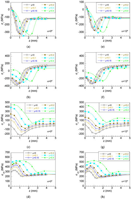
Figure 5.
Stress distributions at the hub edge A of the interface for diverse friction coefficients in conventional hubs: (a) radial stress, (b) tangential stress, (c) axial stress, (d) von Mises stress and chamfer hubs (α = 12°): (e) radial stress, (f) tangential stress, (g) axial stress and (h) von Mises stress.
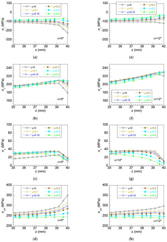
Figure 6.
Stress distributions at the hub edge B of the interface for diverse friction coefficients in conventional hubs: (a) radial stress, (b) tangential stress, (c) axial stress, (d) von Mises stress and chamfer hubs (α = 12°): (e) radial stress, (f) tangential stress, (g) axial stress and (h) von Mises stress.
According to the results, the maximum radial stress on the shaft entry side (Figure 5a) is placed at inner points near the hub surface with values slightly positive at hub edge A. This high stress is progressively decreased as the distance to the hub edge increases to reach a value close to the one given by theoretical expressions at deeper points. As the friction coefficient increases, the maximum radial stress is increased (16%) and is moved towards deeper points. At the hub edge B surroundings (Figure 6a), an interesting effect is observed: as friction is increased, the SC at this hub edge is gradually decreased to disappearance for conventional friction coefficients (μ = 0.3), getting close to the values predicted by theory.
Concerning optimal chamfer hubs (Figure 5e), similar radial stress distributions are obtained, but the maximum radial stresses are lower than the one obtained for conventional hubs (20%). The influence of friction is similar to those previously described for conventional hubs. On hub edge B (Figure 6b), the stress-reducing effect of chamfer hubs in press fits is revealed. This way, the stress at hub edge B for this chamfer angle is similar to the one given by theory and, hence, no SC appears for the frictionless case. Thus, the stress redistribution produced by the increase in stress on the insertion side causes a significant reduction in stress (46%) on the opposite side that is high enough to cancel the SCs at this zone. As friction increases, the radial stress at the hub edge is progressively decreased. Thus, a loss of radial stress at hub surface B as high as 85% is obtained for the highest dry friction case.
Regarding the tangential stress distributions shown in Figure 5c and Figure 6c, similar effects are observed. Thus, the highest stress is located at deeper points out of the hub surface, reaching negative values, and it is progressively increased to reach the value given by theory for deeper points at the interface. As friction increases, the maximum tangential stress is reduced (27%), and it is located at inner points of the interface. Tangential stress at the zone close to hub edge B is linearly and softly increased with the axial coordinate z, up to the hub edge B (Figure 6c) surroundings, where a sudden decrease (11%) in tangential stress is observed. This stress decrease at the hub edge is gradually reduced (14%) as friction is increased.
For chamfer hubs (Figure 5f and Figure 6f), tangential stress distributions exhibit a similar behavior to friction regarding the ones obtained for conventional hubs. In addition, the maximum tangential stress is lower (5%) for chamfer hubs than the ones obtained in conventional hubs. In the same way, the stress at inner points of the interface is also reduced as friction is increased. The tangential stress at points placed near to hub edge B (Figure 6d) is linearly increased, with the axial coordinate z reaching higher values than the ones obtained for the conventional hub case. The effect of friction on stress distribution can be considered as a second-order influence on this side since only a minor increase (2.5%) in stress at hub edge B is observed as the friction coefficient is increased.
Regarding axial stress (Figure 5e and Figure 6e), friction causes significant changes. This way, for conventional hubs considering frictionless cases, the highest stress of a compressive nature is placed out of the hub surface, and for deeper points, the axial stress is reduced to reach a value close to zero. However, as friction is increased, notable changes are generated. Thus, the maximum compressive axial stress is shifted to inner points, and the value of such stress is progressively reduced. However, the stress at hub edge A is gradually increased from a null value corresponding to the frictionless case, reaching maximum values at the hub edge surface of about 450 MPa for the highest friction coefficient (μ = 0.4). At the middle points of the hub–shaft interface, placed far from the high stress zone of the insertion side, the axial stress is uniformly distributed with a drop (54% for frictionless case and 43% for high dry friction case) close to hub edge B (Figure 6e), where the local minimum axial stress is reached. The effect of friction on this side can be considered again as a second-order influence.
For the case of the chamfer hubs (Figure 5g), a similar trend to the friction previously discussed for conventional hubs is observed, but in this case, the maximum stress is reduced with chamfer hubs (10%), and the maximum values reached at the hub edge for high-friction cases are slightly lower (3%) than the ones obtained in the conventional hub. On the opposite side (Figure 6g), a drop in axial stress (60% for the frictionless case and 90% for the highest friction coefficient considered) near hub edge B is observed. As friction increases, the stress drop is more progressive, and the axial stress reductions at hub edge B are higher (70%), reaching stress values close to zero for the highest dry friction case considered. However, the axial stress values on this side are very low (below 40 MPa).
Finally, regarding the von Mises stress for conventional hubs (Figure 5d and Figure 6d), the maximum stress is located at inner points close to hub edge A. For deeper points, the von Mises stress is decreased to reach a value in agreement with theory. As friction increases, the maximum von Mises stress increases (65%), and the position of the maximum value is shifted to inner points, reaching values of about 540 MPa. On the opposite side, the von Mises stress at hub edge B (Figure 6d) is slightly increased with axial coordinate z with a sudden increase (30%) near the hub surface for conventional hubs considering the frictionless case. As friction is increased, the stress is more uniformly distributed, and the local maximum stress placed at hub edge B is progressively reduced to reach similar values to the stress obtained at inner points, thereby canceling the SCs for high values of the friction coefficient.
For chamfer hubs, the von Mises stress distributions (Figure 5h and Figure 6h) match the obtained values in conventional hubs but reach lower stress (5%). This reduction in von Mises stress in chamfer hubs is also observed at hub edge B, where the high SC shown in conventional hubs without friction is lowered. As friction is increased, the same effect is observed, resulting in an almost plain distribution without the SC for high-friction cases at hub edge B.
As a summary, the maximum values of radial, tangential, axial, and von Mises stresses at the interface obtained for different friction conditions are included in Table 1 for conventional hubs and Table 2 for optimal chamfer hubs.

Table 1.
Maximum values of radial, tangential, axial, and von Mises stress distributions in a press fit after assembly for diverse friction conditions on the insertion side (point A) and the opposite side (point B) in conventional hubs (α = 0°).
Table 2.
Maximum values of radial, tangential, axial, and von Mises stress distributions in a press fit after assembly for diverse friction conditions on the insertion side (point A) and the opposite side (point B) in chamfer hubs (α = 12°).
The required axial force, F, for assembly of the shaft into the hub can be obtained by Equation (6) in terms of the contact pressure, p (opposite to radial stress), the friction coefficient (μ), and the hub geometry: hub length, L, and radius at the hub–shaft interface, R [18,63,64], as follows:
According to this equation, the assembly force for conventional hubs considering different friction coefficients is shown in Figure 7a, and, in a similar way, Figure 7b shows the assembly force for optimal chamfer hubs. In both cases, the axial force obtained from the FEM results is compared with the theoretical values given by Equation (6) considering the uniform contact pressure distribution given by Equation (1). As can be observed in Figure 7a,b, a linear growing force is needed for the assembly of the press fit placing the right edge of the shaft out of hub edge B (z > 40 mm), and later, a constant force is needed. Obviously, as the friction increases the assembly force is higher. The obtained results show a good agreement between the FEM results and the values given by theoretical expression (6) for conventional hubs with variations lower than 3% for friction coefficients lower than 0.3 and as high as 4.5% for the highest friction case. The same trend is observed for chamfer hubs, but in this case, the variations are higher (always lower than 10%) than the ones observed in conventional hubs due to the radial stress reductions previously discussed.
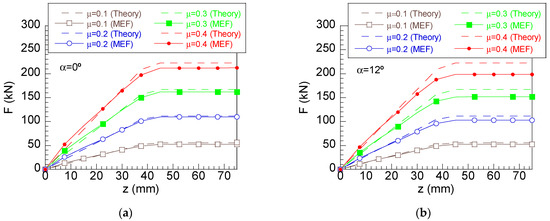
Figure 7.
Axial force required for assembly of a 40H7/s6 press fit (full line) for different friction conditions compared with the theoretical value of the assembly force (dashed line) for (a) conventional hubs and (b) chamfer hubs.
4. Discussion
To go deep in the analysis, additional simulations of the press fit assembly process were carried out for diverse chamfer angles from the conventional hub (α = 0°) to high chamfer angles (α = 20°) according to the sequence α = 0°, α = 5°, α = 7°, α = 9°, α = 10°, α = 12°, α = 15°, α = 17°, and α = 20°, considering for each one of them six different friction coefficients from the frictionless case (μ = 0) to a high dry friction case (μ = 0.4), as follows: μ = 0, μ = 0.1, μ = 0.15, μ = 0.2, μ = 0.3, and μ = 0.4. Once the stress distributions were revealed, SCFs were obtained according to the following expression for radial, tangential, and von Mises stresses:
where σi,max is the maximum value of i-stress, σi,th is the stress given by theory, and i is the component of the stress tensor: radial, tangential, or von Mises. This way, the axial SCF cannot be calculated with Equation (7) since the theoretical value of axial stress does not exist. However, in this study the variation in the maximum stress was also analyzed.
According to results shown in the previous section, the stress distributions at insertion hub edge A and at hub edge B are completely different; consequently, both SCs were considered in this study. Thus, Figure 8 shows the variation with chamfer angle of the SCFs on the insertion side (K*) for different friction coefficients, and in the same way, Figure 9 shows the variations in the SCFs on the opposite side (K**).
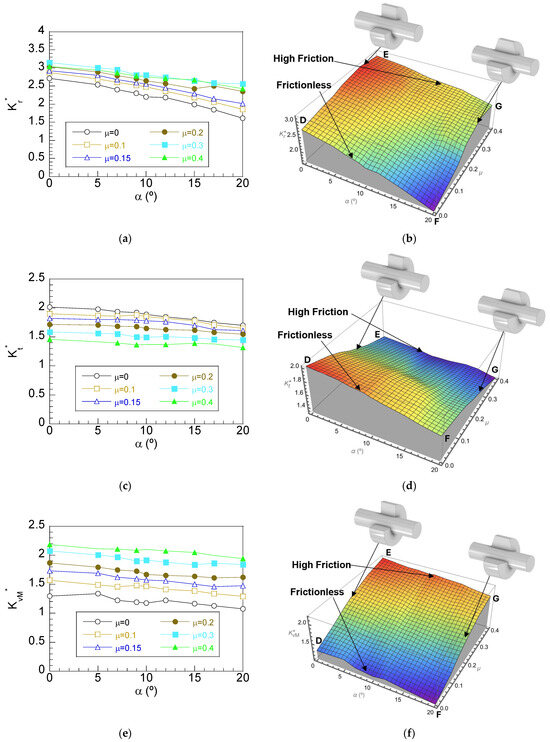
Figure 8.
Variation in SCFs with the chamfer hub angle for diverse friction coefficients in interference fits with chamfer hubs on the insertion side A: (a) radial stress SCF (Kr), (b) Kr 3D plot, (c) tangential SCF (Kt), (d) Kt 3D plot and (e) von Mises SCF (KvM), (f) KvM 3D plot.
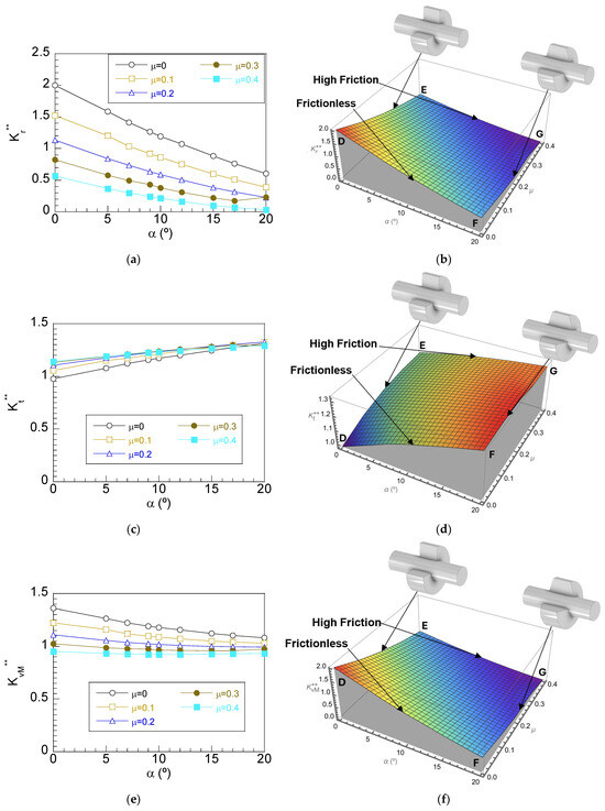
Figure 9.
Variation in SCFs with the chamfer hub angle for diverse friction coefficients in interference fits with chamfer hubs on the right-side B: (a) radial stress SCF (Kr), (b) Kr 3D plot, (c) tangential SCF (Kt), (d) Kt 3D plot and (e) von Mises SCF (KvM), (f) KvM 3D plot.
Regarding the radial SCF (Figure 8a and 3D plot in Figure 8b), it is observed for the frictionless case that Kr* is gradually decreased as the chamfer angle increases, reaching a reduction as high as 40% for the highest chamfer angle (line D–F in Figure 8a). As friction increases, the SCF is increased, but this increment is softer for low chamfer angles and sharper for the highest chamfer angles considered. Thus, for the conventional hubs shown in line D–E in the 3D plot of Figure 8b, a progressive increment of SCFs with friction coefficient is obtained, reaching a maximum increment of 16%. However, for the highest chamfer angle considered (line F–G in Figure 8b), the variation is sharper, reaching an increment of 55% with the friction coefficient. These results show the beneficial effect of chamfer hubs in stress distributions since significant reductions are achieved using high chamfer angles (line D–F in 3D plot of Figure 8b). In addition, the results reveal how the beneficial effect of chamfer hubs is reduced as friction is increased since the curves obtained for high-friction cases exhibit a lower slope and, hence, a lower reduction as low as 18% is obtained for μ = 0.3 or 20% for μ = 0.4 (line E–G in 3D plot of Figure 8b).
This way, friction is revealed as a key factor influencing SCs at the insertion hub edge, increasing the radial SCF. In addition, the chamfer angle is also a factor with a high influence on SCFs; by using the chamfer hub with high chamfer angles, a reduction in the radial SCF of 40% is achieved for the frictionless case. However, this reduction is also affected by friction causing a lower reduction for high friction coefficients; hence, chamfer hubs are less effective for reducing the SCFs for high-friction conditions.
In the case of the tangential SCF, the effect of the chamfer angle is less intense than the one previously observed for the radial SCF. This way, a soft reduction is observed for a frictionless case (line D–F in Figure 8d) with a maximum reduction of 15% reached for the highest chamfer angle considered. This SCF decrement is gradually reduced as the friction increases, reaching an almost plain variation, i.e., with soft reductions in SCFs for high-friction cases, μ = 0.4 (line E–G in 3D plot of Figure 8d). On the other hand, the effect of friction is contrary to the one observed in radial stress; thus, as friction is increased, a reduction in the Kt* as high as 28% for conventional hubs is reached (line D–E in plot 3D of Figure 8d). As was observed for the radial SCF, this reduction is lower as the chamfer angle increases, reaching a 20% reduction for the highest chamfer angle considered (line F–G in plot 3D of Figure 8d). The influence of chamfer hub geometries on the von Mises SCF is less intense, reaching a reduction of 17% for the frictionless case (D–F in Figure 8f) and 10% for the high dry friction (Line E–G in Figure 8f). However, friction is revealed as an influencing factor causing an increment of SCFs for both conventional hubs and chamfer hubs. Thus, friction causes a progressive increment of the von Mises SCF (line D–E in 3d pot of Figure 8f) with an increment of 65% for conventional hubs and reaching increments of about 80% for chamfer hubs with the highest chamfer angle considered (line F–G in 3D plot of Figure 8f).
Regarding the radial SCF at hub edge B (Figure 9a,b), a sudden decrease (70%) of the SCF is obtained for the frictionless case, reaching a value of 1 for α > 15°, or in other words, totally cancelling the SC (line D–F in plot 3D of Figure 9b). A similar non-linear decreasing trend with the chamfer angle is observed for the diverse friction cases analyzed, reaching values close to a null stress for the highest friction coefficient and the highest α analyzed in the study. For friction coefficients higher than 0.2, the SCF is cancelled since the SCF values are lower than 1 for any chamfer angle. In the case of the friction coefficient 0.1, chamfer angles higher than 10° cause the same effect, cancelling the SCF. The effect of friction in conventional hubs (line D–E in Figure 9b) is a non-linear decrement of the SCF as friction is increased, reaching values lower than 1 (again cancelling the SC) for friction coefficients of 0.2 and above. However, for chamfer hubs (line F–G in Figure 9b), this threshold is lower, and this way, all the cases cancel the SCs with radial SCFs below 1 for the highest chamfer angle considered. Thus, as in the case of the radial SCF at insertion hub edge A, chamfer hubs cause a beneficial effect, significantly reducing the radial SC. In addition, friction causes a reduction in the SC, lowering the radial SCF at hub edge B below 1 and hence cancelling the SCs for both the conventional and chamfer hubs.
Tangential SCFs exhibit a non-linear growing trend with the chamfer angle for the frictionless case (line D–F in plot 3D of Figure 9d), reaching increments of 30% for the highest chamfer angle considered. However, the tangential SCF is lower than the radial SCF. For high-friction cases, a similar trend is observed with lower variations (13%) with the chamfer angle (line E–G in plot 3D of Figure 9d). For conventional hubs, friction causes a nonlinear growth of SCs with the friction coefficient (14%, Line D–E in Figure 9d), whereas for chamfer hubs this growth is softer (2%, line F–G in Figure 9d). This way, the variation in the tangential SCF with friction can be considered negligible for α = 20°.
Finally, with regard to the von Mises SCF, a nonlinear variation with the chamfer angle is observed for the frictionless case with high variations for low chamfer angles and soft changes for high chamfer angles (line D–F in plot 3D of Figure 9f). Thus, the chamfer hub allowed the lowering of the SC (30%), showing the beneficial effect of these geometries. For high-friction cases, the variation is softer (2%), and the SC reduction can be considered negligible (line E–G in plot 3D of Figure 9f). The effect of friction consists in a reduction in the SCFs as friction is increased, reaching values close to 1 for high friction coefficients, with reductions as high as 30% for conventional hubs (line D–E in plot 3D of Figure 9f). For the case of high chamfer angles, a softer reduction in the von Mises SCF (14%) is observed (line E–G in plot 3D of Figure 9f) as a result of the synergistic effect of both friction and chamfer hub geometry in lowering SCFs.
Although there is no sense in defining an axial SCF since the theoretical value of this stress does not exist, it seems to be interesting to analyze the variations in the maximum axial stress obtained in simulations since this variable is considered for obtaining the von Mises stress. This way, Figure 10 shows the variation in the maximum axial stress with the chamfer angle for the diverse friction coefficients considered in this study.
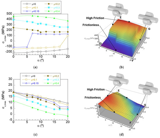
Figure 10.
Variation in the axial stress with the chamfer hub angle for diverse friction coefficients in press fits with chamfer hubs at (a) the hub edge A (σz,max), (b) σz,max 3D plot and (c) the hub edge B (σz,max), (d) σz,max 3D plot.
According to the results, the maximum axial stress is negative (compressive) for low friction coefficients, whereas such stress is positive (tensile) for high values of friction. Thus, for the frictionless case (line D–F in Figure 10b), a soft reduction in the compressive stress is obtained as the chamfer angle is increased and a similar trend is observed for soft friction (μ = 0.1), but in this case, for the highest chamfer angle the maximum axial stress is tensile. A similar effect is observed for the friction coefficient 0.15, where the shift to tensile stress occurs for chamfer angles higher than 5°. For higher friction coefficients, chamfer hubs cause a lowering of the maximum axial stress with reductions of 15% for μ = 0.4 (Line E–G in Figure 10b).
On the other hand, friction is revealed as a key factor in maximum axial stress. This way, for conventional hubs (line D–E in plot 3D of Figure 10b), the compressive axial stress reached for low-friction cases becomes tensile for friction coefficients higher than 0.2 and it nonlinearly grows with the friction coefficient to reach values of about 450 MPa for μ = 0.4. The influence of friction for the chamfer hubs is similar: the maximum stress is compressive for low friction, and as friction is increased (line F–G in plot 3D of Figure 10b), the maximum stress is shifted to tensile, growing nonlinearly with the friction coefficient. This way, friction is revealed as a factor with a high influence on the axial SC, causing high axial stress for high friction coefficients. It deserves to be highlighted that the maximum axial stress at hub edge A is placed at inner points of the shaft–hub interface out of the hub surface.
Regarding the axial stress at hub edge B (Figure 10c,d), the maximum values obtained are notably lower (one order of magnitude) than the ones revealed on the insertion side, and consequently, they can be considered negligible. However, the analysis of results reveals that the chamfer angle reduces the axial stress (placed at hub edge B) for the frictionless case (line D–F in plot 3D of Figure 10d) with a maximum reduction of 50% for the highest chamfer angle considered. A similar decreasing trend with the increment of the chamfer angle is observed for the high-friction case (line E–G in plot 3D of Figure 10d).
Friction causes a reduction in the axial stress at hub edge B. Thus, in conventional hubs, as friction is increased the axial stress is reduced, reaching the lowest value for μ = 0.4 (line D–E in plot 3D of Figure 10d). A similar effect occurs for chamfer hubs, but in this case, the values of axial stress become null for the highest friction and the highest chamfer angles considered (line F–G in plot 3D of Figure 10d).
5. Conclusions
In this study, the key influences of friction and manufacturing-induced plastic strains on stress distributions at the shaft–hub interface are revealed. The assembly process of a press fit generates a localized plastic strain zone at the insertion hub edge surroundings that causes a non-uniform distribution of stress at the shaft–hub interface. This way, high stress is located at the insertion hub edge, and low stress is placed on the opposite side. In addition, the manufacturing of a press fit causes significant axial stress near to the insertion hub edge that is not considered in design equations. Friction is a parameter with a high influence on stress fields, causing an increment of radial and von Mises stresses at the insertion hub edge and a reduction in the tangential stress. In addition, friction produces a significant stress reduction on the opposite side, cancelling the radial and von Mises stress concentrations.
Chamfer angle was revealed as a key influencing factor on stress fields that reduce stress concentrations at both hub edges. Thus, the use of chamfer hubs causes reductions in the radial SCF at the insertion hub edge as high as 40% for the frictionless case and 20% for high dry friction with soft reductions in the tangential SCF (15% for frictionless and 10% for high dry friction) and the von Mises SCF (17% for frictionless and 10% for high dry friction). However, the most remarkable change is produced on the opposite hub edge, where a significant reduction in the manufacturing-induced radial and von Mises SCFs is obtained even for high-friction cases. This way, the use of optimal chamfer hubs with chamfer angles of 15–20° is highly recommended for minimizing the increment of friction-induced stress concentrations during the manufacturing process of a press fit.
Author Contributions
Conceptualization, M.L. and E.I.; data curation, M.L. and E.I.; formal analysis, M.L. and E.I.; funding acquisition, M.L.; investigation, M.L., E.I., M.R.-M. and R.G.-M.; methodology, M.L. and E.I.; software, M.L. and E.I.; supervision, M.L., M.R.-M. and R.G.-M.; validation, M.L.; writing—original draft preparation, M.L. and E.I.; writing—review and editing, M.L., E.I., M.R.-M. and R.G.-M. All authors have read and agreed to the published version of the manuscript.
Funding
This research was funded by the Fundación Memoria D. Samuel Solorzano Barruso, grant numbers FS/32–2017 and FS/12–2021 and Ministerio de Ciencia, Innovación y Universidades MCIN/AEI/10.13039/501100011033, grant number PID2020–119003GB–I00.
Data Availability Statement
The original contributions presented in the study are included in the article, further inquiries can be directed to the corresponding author.
Conflicts of Interest
The authors declare no conflicts of interest.
References
- Zdravecká, E.; Ondáč, M.; Tkáčová, J.; Vojtko, M.; Slota, J. Failure analysis of the pulleys during the press-fit assembling process. Case Stud. Eng. Fail. Anal. 2015, 3, 34–38. [Google Scholar] [CrossRef][Green Version]
- Chu, S.J.; Jeong, T.K.; Jung, E.H. Effect of radial interference on torque capacity of press-and shrink-fit gears. Int. J. Automot. Technol. 2016, 17, 763–768. [Google Scholar] [CrossRef]
- Shu, Y.; Yang, G.; Liu, Z. Experimental study on fretting damage in the interference fit area of high-speed train wheels and axles based on specimen. Eng. Fail. Anal. 2022, 141, 106619. [Google Scholar] [CrossRef]
- Murcinkova, Z.; Baron, P.; Pollak, M. Study of the press fit bearing-shaft joint dimensional parameters by analytical and numerical approach. Adv. Mater. Sci. Eng. 2018, 1, 2916068. [Google Scholar] [CrossRef]
- Wang, T.; Guo, H.; Qiao, J.; Liu, X.; Fan, Z. Experimental study on the relationship between the friction coefficient and interference in locomotive axle press-fitting. Int. J. Struct. Integr. 2021, 12, 878–893. [Google Scholar] [CrossRef]
- Wang, X.; Lou, Z.; Wang, X.; Xu, C. A new analytical method for press-fit curve prediction of interference fitting parts. J. Mater. Process. Technol. 2017, 250, 16–24. [Google Scholar] [CrossRef]
- Tohmyoh, H.; Yamanobe, K.; Saka, M.; Utsunomiba, J.; Nakamura, T.; Nakano, Y. Determination of the friction coefficient of a press fit pin in thin plating. JSME Int. Ser. Solid Mech. Mater. Eng. 2006, 49, 363–369. [Google Scholar] [CrossRef][Green Version]
- Levitas, V.I.; Idesman, A.V.; Nemirosvskii, A.B.; Nemirovskii, Y.B.; Zherebtsov, Y.V.; Stashkevich, I.E.; Gerovskoo, A.I. Numerical modelling of the process of press fitting dies into ring blocks with allowance for plastic deformation and frictional forces. Strength Mater. 1990, 22, 1675–1682. [Google Scholar] [CrossRef]
- Zehsaz, M.; Shahriary, P. The effects of friction coefficient and interference on the fretting fatigue strength of railway axle assembly. Int. Union Railw. 2013, 75, 71–84. [Google Scholar]
- Norton, R.L. Machine Design, 5th ed.; Prentice Hall: New York, NY, USA, 2013. [Google Scholar]
- Zhao, J.; Wang, J.X.; Yu, C.; Tang, S.Q.; Yao, J. Influence of radial interference on torque capacity of shrink-fit cam shaft. Adv. Mech. Eng. 2019, 11, 1687814018817640. [Google Scholar] [CrossRef]
- Nwe, T.; Pimsarn, M. Railway axle and wheel assembly press-fitting force characteristics and holding torque capacity. Appl. Sci. 2021, 11, 8862. [Google Scholar] [CrossRef]
- Baugher, J.W. Transmission of torque by means of press and shrink fits. Trans. ASME 1931, 53, 85–89. [Google Scholar] [CrossRef]
- Post, C.E.; Bitter, T.; Briscoe, A.; Verdonschot, N.; Janssen, D. A FE study on the effect of interference fit and coefficient of friction on the micromotions and interface gaps of a cementless PEEK femoral component. J. Biomech. 2022, 137, 310–322. [Google Scholar] [CrossRef]
- Loc, N.H.; Phong, L.V. Study of interference fit between steel and brass parts. EUREKA Phys. Eng. 2022, 5, 140–149. [Google Scholar] [CrossRef]
- Yang, G.M.; Coquille, J.C.; Fontaine, J.F.; Lambertin, M. Influence of roughness on characteristics of tight interference fit of a shaft and a hub. Int. J. Solids Struct. 2001, 38, 7691–7701. [Google Scholar] [CrossRef]
- Persson, B.N.J. Influence of surface roughness on press fits. Tribol. Lett. 2023, 71, 19. [Google Scholar] [CrossRef]
- Shigley, J.E.; Mischke, C.R. Standard Handbook of Machine Design, 11th ed.; McGraw Hill: New York, NY, USA, 1988. [Google Scholar]
- Campos, U.A.; Hall, D.E. Simplified Lamé’s equations to determine contact pressure and hoop stress in thin-walled press-fits. Thin Wall. Struct. 2019, 138, 199–207. [Google Scholar] [CrossRef]
- Strozzi, A.; Baldini, A.; Giacopini, M.; Bertocchi, E.; Bertocchi, L. Achievement of a uniform contact pressure in a shaft-hub press-fit. Proc. Inst. Mech. Eng. Part C J. Mech. Eng. Sci. 2013, 227, 405–419. [Google Scholar] [CrossRef]
- Irena, K.A.; Lemu, H.G.; Kedir, Y.A. Effect of interference size on contact pressure distribution of railway wheel axle press fitting. Designs 2023, 7, 119. [Google Scholar] [CrossRef]
- Wang, X.; Lou, Z.; Wang, X.; Hao, X.; Wang, Y. Prediction of stress distribution in press-fit process of interference fit with a new theoretical model. Proc. Inst. Mech. Eng. Part C J. Mech. Eng. Sci. 2018, 233, 2834–2846. [Google Scholar] [CrossRef]
- Prasad, N.S.; Sashikanth, P.; Ramamurti, V. Stress distribution in interference joints. Comput. Struct. 1994, 51, 535–540. [Google Scholar] [CrossRef]
- Zhou, Y.; Lin, Q.; Shao, H.; Wang, C.; Li, X.; Hong, Y. Stress-based optimization of assembly surface mechanical properties oriented to stress-uniform assembly. Precis. Eng. 2023, 82, 350–359. [Google Scholar] [CrossRef]
- Yamamoto, M.; Ishiduka, H. Stress concentration of transition groove induced by a press-fitted part in railway axles. Int. J. Fatigue 2017, 97, 48–55. [Google Scholar] [CrossRef]
- Song, C.; Liu, J.; Peng, J.; Zhang, L.; Zhou, Y.; Zhu, M. Effect of contact stress on rotating bending fretting fatigue life of railway axle steel. J. Mater. Eng. 2014, 1, 34–38. [Google Scholar] [CrossRef]
- Nwe, T.; Pimsarn, M. Effect of interference on the press fitting of railway wheel and axle assemblies. Mater. Sci. Eng. 2021, 1137, 012051. [Google Scholar] [CrossRef]
- Falter, J.; Binz, H.; Kreimeyer, M. Investigations on design limits and improved material utilization of press-fit connections using elastic-plastic design. Appl. Eng. Sci. 2023, 13, 100124. [Google Scholar] [CrossRef]
- You, B.; Luo, Y.; Wang, X.D. The application of computing methods for analysis of press-fit assembly in elasto-plastic field. J. Inf. Comput. Sci. 2014, 11, 3157–3166. [Google Scholar] [CrossRef]
- Zou, L.; Zeng, D.; Wang, J.; Lu, L.; Li, Y.; Zhang, Y. Effect of plastic deformation and fretting wear on the fretting fatigue of scaled railway axles. Int. J. Fatigue 2020, 132, 105371. [Google Scholar] [CrossRef]
- Hüyük, H.; Music, O.; Koç, A.; Karadogan, C.; Bayram, C. Analysis of elastic-plastic interference-fit joints. Proc. Eng. 2014, 81, 2030–2035. [Google Scholar] [CrossRef]
- Izard, E.; Garcia-Martín, R.; Rodríguez-Martín, M.; Lorenzo, M. Influence of the Friction Coefficient on the Stress Distributions and Contact Pressure in Press-Fits via Finite Element Analysis. Lubricants 2023, 11, 472. [Google Scholar] [CrossRef]
- Dieudonné, E.; Florence, O.; Joseph, N.A.; Valerya, N.A.C.; Achillea, N.P.A.; Nelson, Z.C. A study on the experimental investigation of low frequency vibration wave assisted disassembly of press-fit joints. J. Manuf. Process. 2020, 49, 70–81. [Google Scholar] [CrossRef]
- Dong, Y.; Zeng, D.; Zhao, H.; Wu, P.; Song, Y.; Li, X.; Lu, L. Fretting fatigue strength evaluation of scaled press-fitted railway axle containing a circumferential groove defect. Int. J. Fatigue 2025, 194, 108824. [Google Scholar] [CrossRef]
- Bian, X.; Wei, C.; Lui, Y. Research on the fretting contact fatigue strength of interference fit in high speed rail traction motor shafts. Eng. Fail. Anal. 2024, 157, 107875. [Google Scholar] [CrossRef]
- Zou, L.; Zeng, D.; Chen, X.; Li, J.; Zhao, H.; Lu, L. Experimental and numerical study on press-fitted railway axles: Competition between fretting and plain fatigue. Int. J. Fatigue 2024, 179, 108032. [Google Scholar] [CrossRef]
- Kowalski, S. The analysis of fretting fatigue in forced-in joint with the induction- hardened shaft. Tribol. Finn. J. Tribol. 2021, 38, 11–21. [Google Scholar] [CrossRef]
- Zou, L.; Lu, L.; Li, Y.; Yang, K.; Zhao, H.; Dong, Y.; Zeng, D. Experimental and numerical study on press-fitted railway axles: Fretting fatigue behaviour in the very high cycle regime. Int. J. Fatigue 2023, 166, 107243. [Google Scholar] [CrossRef]
- Pourheidar, A.; Regazzi, D.; Cervello, S.; Foletti, S.; Beretta, S. Fretting fatigue analysis of full-scale railway axles in presence of artificial micro-notches. Tribol. Int. 2020, 150, 106383. [Google Scholar] [CrossRef]
- Shu, Y.; Yang, G.; Liu, Z. Simulation research on fretting wear of train axles with interference fit based on press-fitted specimen. Wear 2023, 523, 204777. [Google Scholar] [CrossRef]
- Zou, L.; Zeng, D.; Dong, Y.; Li, J.; Chen, X.; Zhao, H.; Lu, L. Experimental and numerical study on the fretting wear-fatigue interaction evolution in press-fitted axles. Int. J. Fatigue 2023, 175, 107793. [Google Scholar] [CrossRef]
- Zhang, Y.; Lu, L.; Gong, Y.; Zhang, J.; Zeng, D. Fretting wear-induced evolution of surface damage in press-fitted shaft. Wear 2017, 384–385, 131–141. [Google Scholar] [CrossRef]
- Xiao, H.; Sun, Y.; Xu, J. Slip damping of a press-fit joint under non uniform pressure distribution along the interface. J. Mech. Mater. Struct. 2020, 15, 307–323. [Google Scholar] [CrossRef]
- Xu, T.; Lu, L.; Zeng, D.; Zou, L. Fretting fatigue crack growth simulation and residual life assessment of railway press-fitted axle. Eng. Fract. Mech. 2023, 286, 109290. [Google Scholar] [CrossRef]
- Zou, L.; Zeng, D.; Zhang, Y.; Lu, L.; Zhao, H.; Xu, T.; Shi, G.; Chen, H. A coupled wear and crack initiation-propagation methodology for fretting fatigue life assessment in press-fitted axles. Int. J. Fatigue 2022, 159, 106817. [Google Scholar] [CrossRef]
- Gürer, G.; Gür, C.H. Failure analysis of fretting fatigue initiation and growth on railway axle press-fits. Eng. Fail. Anal. 2018, 84, 151–166. [Google Scholar] [CrossRef]
- Zou, L.; Zeng, D.; Tian, X.; Jiang, G.; Dong, Y.; Zhao, H.; Lu, L. Experimental and numerical study on the multi-site fretting fatigue crack initiation of press-fitted axles. Fatigue Fract. Eng. Mater. Struct. 2024, 47, 473–490. [Google Scholar] [CrossRef]
- Dong, Y.; Zeng, D.; Wu, P.; Lu, L.; Zhao, H.; Li, Y.; Zou, L. Study on fretting fatigue crack initiation of scaled railway axles in consideration of fretting wear. Wear 2023, 512–513, 204545. [Google Scholar] [CrossRef]
- Ubando, A.T.; Gonzaga, J.; Arriola, E.; Moran, R.L.; Lim, N.R.E.; Mercado, J.P.; Belarmino, D. Analysis of the effects of geometry on the press fit application in automotive power modules. IOP Conf. Ser. Mater. Sci. Eng. 2021, 1109, 012019. [Google Scholar] [CrossRef]
- Lorenzo, M.; Blanco, C.; Moreno, P.; Pérez-Cerdán, J.C. Influence of geometry on the stress peaks in interference fits with grooved hub. DYNA 2016, 91, 47–51. [Google Scholar] [CrossRef]
- Lee, D.H.; Choi, H.Y.; Song, C.Y.; Lee, B.G. Design of stress relief groove on a press-fitted assembly. Adv. Mater. Res. 2013, 753–755, 1339–1342. [Google Scholar] [CrossRef]
- Izard, E.; García-Martín, R.; Rodríguez-Martín, M.; Lorenzo, M. Finite element analysis of the influence of chamfer hub geometry on the stress concentrations of shrink fits. Appl. Sci. 2023, 13, 3606. [Google Scholar] [CrossRef]
- Pedersen, N.L. On optimization of interference fit assembly. Struct. Multidiscip. Optim. 2016, 54, 349–359. [Google Scholar] [CrossRef]
- Izard, E.; Garcia, R.; Rodriguez-Martín, M.; Lorenzo, M. Finite element analysis of the reduction in stress concentration factors in shrink fits by using contact rings. Appl. Sci. 2022, 12, 10037. [Google Scholar] [CrossRef]
- Güven, U. Stress distribution in shrink fit with elastic-plastic hub exhibiting variable thickness. Int. J. Mech. Sci. 1993, 35, 39–46. [Google Scholar] [CrossRef]
- Arslan, E.; Mack, W. Shrink fit with solid inclusion and functionally graded hub. Compos. Struct. 2015, 121, 217–224. [Google Scholar] [CrossRef]
- Apatay, T.; Arslan, E.; Mack, W. Effects of homogeneous and inhomogeneous heating on rotating shrink fits with annular inclusion and functionally graded hub. J. Therm. Stress. 2019, 42, 1458–1479. [Google Scholar] [CrossRef]
- Wang, R.; Xu, L. Mechanical behavior investigation of press-fit connector based on finite element simulation and its reliability evaluation. Microelectron. Reliab. 2021, 116, 114010. [Google Scholar] [CrossRef]
- Shu, Y.; Liu, Z.; Yang, G. Finite element simulation of fretting wear on railway axle press-fit specimens. Tribol. Int. 2023, 178, 108024. [Google Scholar] [CrossRef]
- Sarabandi, S.; Soleimani, H.; Mahmoudi, S. The 3-D finite-element analysis of press fitting process in railway wheel-set. Sci. Iran. 2019, 26, 367–374. [Google Scholar] [CrossRef]
- Gao, Z.; Meng, X.Y.; Guan, S. Simulation and analytical study of the process parameters of the press-fit method. Int. J. Nanomanuf. 2024, 19, 1–22. [Google Scholar] [CrossRef]
- ISO 286-1:2010; Geometrical Product Specifications (GPS)—ISO Code System for Tolerances on Linear Sizes—Part 1: Basis of Tolerances, Deviations and Fits. International Organization for Standardization: Geneve, Switzerland, 2010; p. 38.
- Maxim, D.I.; Marsavina, L.; Rusu, L. The effect of manufacturing on the press fit insertion force. IOP Conf. Ser. Mater. Sci. Eng. 2018, 416, 012050. [Google Scholar] [CrossRef]
- Wang, M.; Hou, B.; Wang, W. Deep-learning-coupled numerical optimization method for designing geometric structure and insertion-withdrawal force of press-fit connector. Acta Mech. Solida Sin. 2025, 38, 78–90. [Google Scholar] [CrossRef]


Disclaimer/Publisher’s Note: The statements, opinions and data contained in all publications are solely those of the individual author(s) and contributor(s) and not of MDPI and/or the editor(s). MDPI and/or the editor(s) disclaim responsibility for any injury to people or property resulting from any ideas, methods, instructions or products referred to in the content. |
© 2025 by the authors. Licensee MDPI, Basel, Switzerland. This article is an open access article distributed under the terms and conditions of the Creative Commons Attribution (CC BY) license (https://creativecommons.org/licenses/by/4.0/).