1. Introduction
Rolling bearings are widely used in the aerospace industry and are critical components for ensuring the stable operation of rotor systems in aerospace engines [
1]. To withstand extreme operational environments such as cryogenic temperatures, high pressures, and vacuum conditions, rolling bearings are often lubricated using solid lubrication or self-lubricating methods. During the startup process of aerospace engine equipment, where rotor system speeds must be rapidly increased within a short time frame, the rolling bearings are highly susceptible to skidding phenomena [
2]. According to the study by Chase et al. [
3], lubrication failure and inadequate heat dissipation are the primary causes of failure in solid-lubricated ball bearings used in the turbopumps of liquid rocket engines. During intense acceleration phases, rolling bearings are subjected to severe skidding [
4,
5]. The skidding behavior not only accelerates abrasive wear of the solid lubricant coating [
6,
7,
8] but also contributes to an increase in bearing temperature, eventually leading to thermal failure [
9,
10]. Therefore, investigating the skidding mechanisms and characteristics of solid-lubricated rolling bearings during acceleration is of significant importance in mitigating slip, reducing wear, and enhancing the operational lifespan of aerospace engine bearings.
A significant amount of research has been conducted on the skidding phenomena in rolling bearings. Harris [
11], Liao [
12], and Oktaviana [
13] studied the influence of various load parameters on bearing skidding based on quasi-static analysis models of rolling element bearings (REBs). Utilizing the elastohydrodynamic lubrication theory and rolling bearing dynamic models, Jain et al. [
14] investigated the skidding mechanisms of ACBBs under different load conditions. Scholars such as Tu [
15,
16], Han [
17,
18], Zhao [
19], Liu [
20], and Gao [
21] have also examined the influence of different operating parameters on bearing skidding characteristics based on dynamic models of rolling bearings. Atef et al. [
22] studied the influence of operating conditions, lubricant properties, and geometry design on the skidding behavior of REBs using an improved nonlinear dynamic model. Based on the dynamic model and a test rig that can reflect the effect of skidding rate on cage rotational speed and outer ring temperature, Liu et al. [
23] found that skidding can be alleviated by improving the heat dissipation efficiency. Utilizing a rotor-bearing dynamic model, Wang et al. [
24] revealed the correlation mechanism between bearing skidding and cage stability of REBs. In addition to classical analytical theories of rolling bearings, some researchers have employed finite element and experimental methods to explore bearing skidding. Han et al. [
25] established a finite element dynamic model of high-speed cylindrical roller bearings using Abaqus software, analyzing the effects of speed, load, and friction on slip behavior. Jing et al. [
26] investigated the slip rate of the cage using a cylindrical roller–rotor test rig and explored the relationship between slip rate and bearing fault frequency. Skidding behavior exhibits a certain degree of concealment, and its fault characteristics are relatively subtle compared to defect-induced failures. Currently, researchers primarily focus on monitoring skidding behavior by combining its underlying mechanisms with emerging techniques such as artificial intelligence [
27,
28,
29] and triboelectric nanogenerators (TENGs) [
30,
31].
Most of the existing research on bearing skidding is conducted on oil-lubricated bearings. In the context of solid lubricants or dry friction, Hailing [
32] was the first to introduce the rolling contact traction force model, commonly used in wheel–rail contact dynamics analysis, into ball bearings to study the rolling contact mechanism of solid-lubricated bearings. However, this model did not account for the spinning motion of the steel balls. Subsequently, Kalker [
33], using his derived simplified rolling contact theory [
34] and the simplified algorithm FASTSIM [
35], developed a complete traction model for the steel balls. On this basis, Legrand et al. [
36] established an overall quasi-static analysis model for ACBBs that considered axial preload. However, this model neglected the centrifugal force and gyroscopic torque of balls. Zhao et al. [
19,
37] extended this further by considering the inertia effects of the balls and the curvature of the contact surfaces, resulting in a quasi-static analysis model for solid lubrication/dry contact ACBBs under combined loading conditions. Currently, research on solid-lubricated ball bearings primarily employs quasi-static analysis methods for steady-state analysis of the motion states, traction forces, and slip behaviors of bearing components. However, the quasi-static model cannot capture the transient characteristics of bearings under varying load or speed conditions, thus making it unsuitable for analyzing the dynamic friction and skidding characteristics of rolling bearings during acceleration or deceleration processes.
Based on the above analysis, the tribological interaction between rolling elements and raceways is the most critical factor influencing the skidding behavior of REBs. For solid-lubricated ball bearings, this interaction typically involves skidding, over-skidding, spinning, and creepage. Existing semi-empirical tribological models for solid lubrication are incapable of capturing spinning and micro-slip behavior, while quasi-static tribological models based on rolling contact theory are insufficient to reveal the dynamic skidding behavior of bearings during rapid acceleration and deceleration processes.
In light of this, the present study adopts Gupta’s dynamic modeling method [
38] for rolling bearings and Kalker’s simplified rolling contact theory to consider the multi-degree-of-freedom motion of the inner ring, outer ring, rolling elements, and cage. To address the computational challenges posed by the incorporation of complex tribological behaviors into the dynamic model, an interpolation-based approach is proposed to efficiently obtain the contact parameters between rolling elements and raceways in real time, thereby improving computational efficiency. In addition, the results from the authors’ previously developed solid-lubricated quasi-static tribological model are used as initial conditions for the frictional dynamic model to enhance the convergence speed of the differential equations. On this basis, the skidding mechanisms and characteristics of solid-lubricated ACBBs during the acceleration process are analyzed. This study is expected to provide theoretical insights for ensuring the operational reliability and lifespan of solid-lubricated rolling bearings in aerospace engines.
2. Tribo-Dynamic Modelling Based on Rolling Contact Theory
Contact and traction forces are the primary driving sources for the rolling elements in ACBBs and form the foundation for establishing the dynamic equations of the bearing components. Based on the fundamental theory of rolling bearing dynamics and solid lubrication rolling contact theory, the contact force and traction force models for ACBBs are introduced in this section. On this basis, a set of differential equations are developed for ACBBs using the expressions of forces and torques.
To emphasize the core aspects of the theoretical analysis and improve computational efficiency, several assumptions are made in the modeling process, as detailed below:
(1) Neglect of thermal effects: For solid-lubricated rolling bearings, the tribological properties of the lubricating material between the rolling elements and raceways are minimally influenced by temperature. Therefore, thermal effects are omitted in this study.
(2) Hertzian contact assumption: Given that the solid lubricant coating in such bearings is typically less than 10 μm thick and possesses considerable hardness, the contact between rolling elements and raceways is reasonably approximated by Hertzian contact theory, introducing negligible error.
(3) Half-space assumption: This approach simplifies the contact problem between the rolling elements and raceways to a localized one. Since the size of the contact area is much smaller than that of the contacting bodies, this assumption does not significantly affect the accuracy of the model.
(4) Neglect of cage flexibility: To preserve self-lubricating properties, cages in solid-lubricated ball bearings are typically made of PTFE or bronze, materials known for their low elastic deformation. Thus, the cage is treated as a rigid body.
2.1. Calculation of Contact Forces and Contact Deformations
In order to accurately describe the motion of each bearing component, three types of coordinate systems are established, as shown in
Figure 1. As seen in
Figure 1a,
O-
XYZ represents the bearing’s inertial coordinate system, which is primarily used to describe the absolute positions of the rolling elements, raceways, and cage in a 3-dimensional space. The
o-
xbybzb coordinate frame shown in
Figure 1b is the moving coordinate system of the ball, characterizing the rotational motion of the rolling element with respect to the inertial reference frame. In addition,
oi-
xiyizi and
oo-
xoyozo are the local coordinate systems for the inner and outer contacts, respectively, which is employed to describe the contact and friction forces between rolling elements and raceways. Finally, the
op-
xpypzp frame is the coordinate system for the ball–cage pocket contact.
Let the six translational degree-of-freedoms (DOFs) of the ball be
yb,
zb,
ωbm,
ωbx,
ωby, and
ωbz, where
yb and
zb represent the displacements of the rolling element along the
yb and
zb axes in the moving coordinate system, respectively. According to the deformation coordination relationship of the ball [
39], the contact angle at any given moment can be derived as follows:
where
A0 is the distance between the raceway curvature center and the ball geometry center. The contact force between the ball and the raceway can be expressed as follows [
39]:
where
κ and
δ are the contact stiffness and deformation, respectively. The contact stiffness is calculated as follows [
40]:
where
k is the ellipticity of the contact patch;
E’ is the equivalent modulus of elasticity;
F and
ε are the first and second types of elliptic integrals of
k, respectively; and
R is the radius of curvature of the raceway. To improve the efficient of the dynamic model, the ellipticity corresponding to different contact angles can be calculated in advance, and the required values can be obtained directly through interpolation in the dynamic solution process [
41].
As shown in
Figure 1c, due to the clearance in the cage pocket, an elastic force is generated only when the ball comes into contact with the pocket wall. Assuming the rotational displacement of a ball is
θm and that of the cage is
θc, with their angular difference denoted as Δ
θ, and
rp representing the pitch radius of the ball, the contact force exerted on the cage pocket by the ball can be expressed, under the small deformation assumption, as follows:
where
Fcbk denotes the contact force exerted by the
k-th ball on the corresponding cage pocket;
rp is the pitch radius of the ball;
Kcb and
Ccb are the contact stiffness and damping coefficient between the ball and the cage pocket, respectively; and
θcl is the clearance angle of the cage pocket. Accordingly, the total driving torque exerted on the cage can be expressed as follows:
where
Nb is the number of balls.
2.2. Traction Modelling Based on Rolling Contact Theory
The proposed tribo-dynamic model primarily considers the frictional interactions among the rolling elements, raceways, and cage. Since the cage possesses only one rotational degree of freedom, the guiding force and friction between the cage and the rings are not taken into account. The friction between the cage and the rolling elements is modeled using a Coulomb sliding friction model, while the contact between the rolling elements and the raceways is described using Kalker’s simplified rolling contact model.
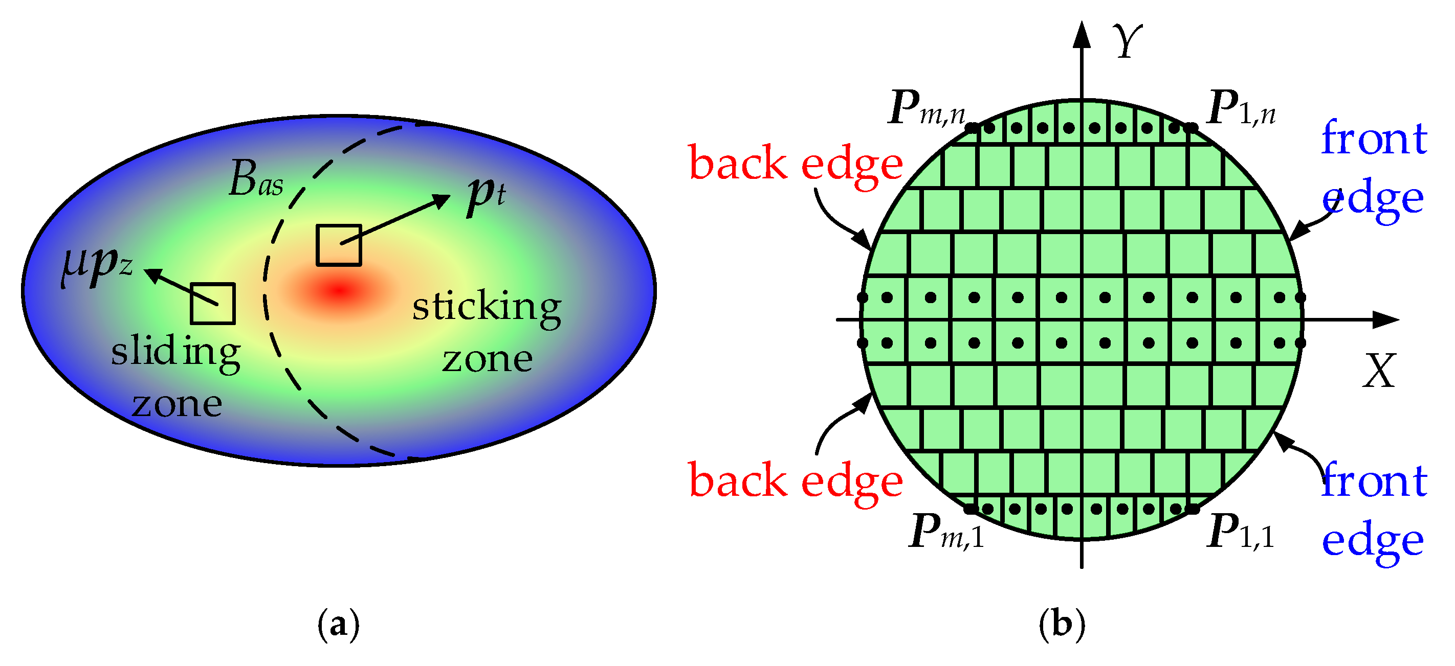
Unlike the hydrodynamic lubrication mechanism found in fluid-lubricated systems, frictional behavior in solid-lubricated or dry-lubricated contacts is primarily governed by rolling contact friction. Due to tangential elastic deformation at the contact interface, two bodies undergoing relative rolling may exist in a state that is neither full macroscopic slip nor pure rolling. In this condition, both sliding and sticking zones coexist within the contact patch—a phenomenon known as creepage. The corresponding tribological model is illustrated in
Figure 2, where
Bas means the boundary between the sliding zone and the sticking zone,
μPz is the sliding vector of the sliding particle, and
pt is the tangential elastic force of the sticking particle.
According to the simplified rolling contact theory [
42], the tangential deformation at any given contact point is solely determined by the stress acting on that point. Therefore, the stress experienced by a rolling contact particle can be inversely determined from its displacement as follows:
where
Px/y,
L, and
ux/y are the stress, elastic coefficient, and deformation of the particle, respectively, in the tangential direction. Based on the simplified rolling contact theory, the contact region is discretized into a finite number of grid elements, as illustrated in
Figure 2b. The tangential stress at the center of each grid element is then iteratively derived, starting from the leading edge of the contact region as follows [
34]:
where
s denotes the average rolling velocity vector,
c represents the creepage vector, Δ
t is the contact time step, and
l is the contact path length. By integrating the stresses acting on all the discrete particles, the total traction force over the entire contact patch can be obtained as follows:
The concentrated traction torque acting on the ball is expressed as follows:
where
M denotes the concentrated traction torque vector,
T is the traction force vector, and
rb is the radius of the ball. With the contact force, traction force, and traction torque determined, the dynamic equations of each bearing component can be established based on the Gupta dynamic model.
2.3. Dynamic Equations of the System
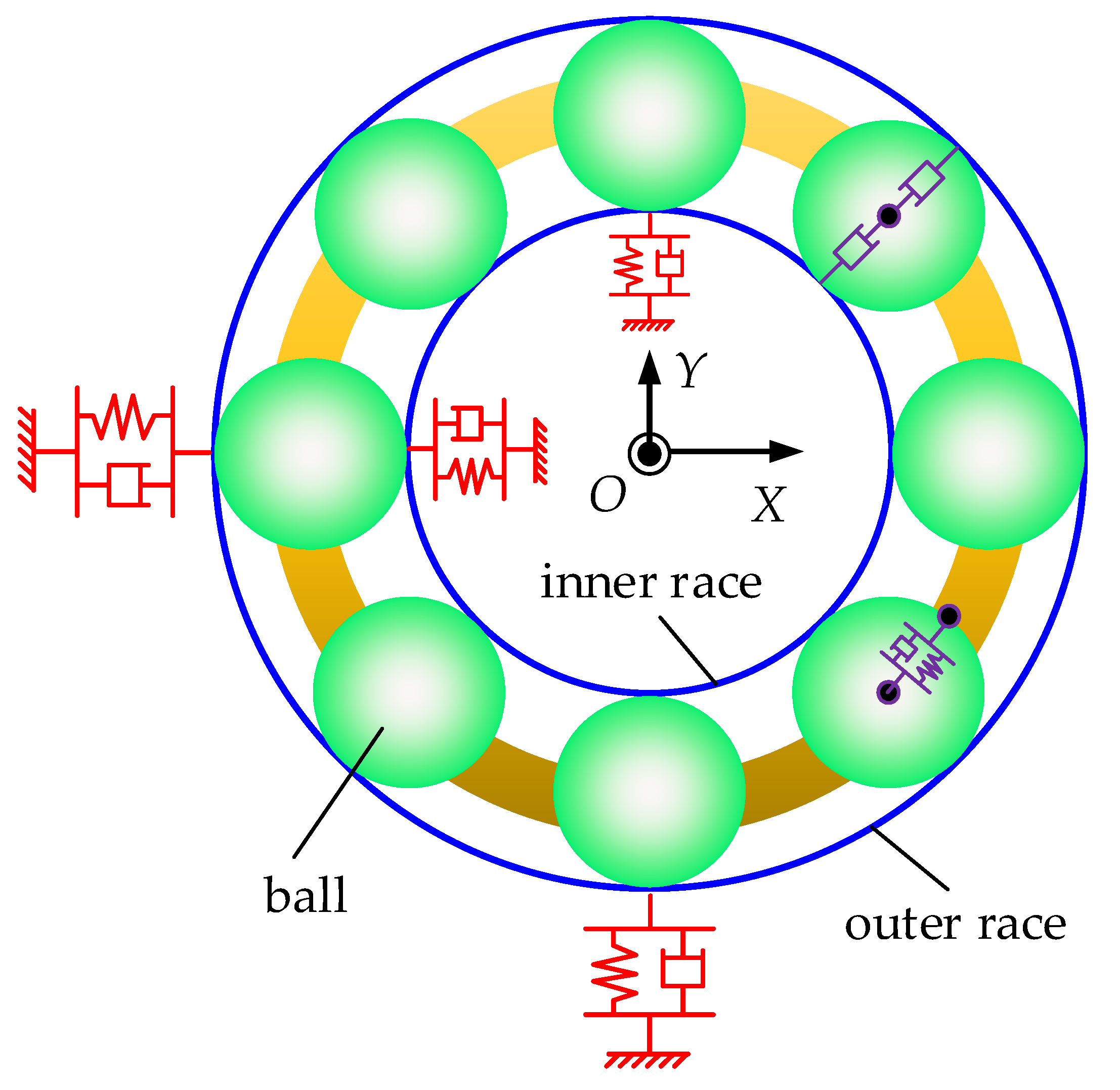
The dynamic model of the system is illustrated in
Figure 3. As the inner ring is subjected to both axial preload and radial force, it possesses three translational DOFs. The corresponding differential equations are given as follows:
The bearing outer ring is considered as a fixed component. However, to simulate its vibration response, it is assigned two translational DOFs. The differential equations of the outer ring are given as follows:
The primary function of the cage is to constrain the circumferential position of the rolling elements and to reflect the acceleration process of the bearing. It has one rotational degree of freedom, and the equation of motion is given as follows:
The ball has six DOFs. Since elastic deformation has already been accounted for when calculating the contact forces, the equation of motion for the ball excludes the stiffness terms and includes only the damping terms. The equation of motion for the translational movement is given as follows:
In Equations (11)–(19), Mi, Mo, and Mb are the masses of the inner ring, outer ring, and ball, respectively; the subscripts I, o, and b represent the inner race, outer race, and rolling element, respectively; subscripts x, y, and z represent the force components in the x, y, and z directions, respectively; C and K are the damping and stiffness coefficient, respectively; Fx/y/z is the load acting on the inner ring; Mc is the resultant torque acting on the cage from the balls; Fc is the centrifugal force of the ball; and Qn is the normal contact force exerted on the ball.
The equation of motion for the rolling element’s three-dimensional rotational motion is given as follows:
where
Ic represents the moment of inertia of the cage;
ωm is the angular velocity of the ball’s revolution;
Mg is the gyroscopic torque;
Mx/y/z are the traction torques in the respective directions;
θbx,
θby, and
θbz represent the rotational displacements of the rolling element about the local axes
xb,
yb, and
zb, respectively.
In this study, the aforementioned system of differential equations is solved using the fourth-order Runge–Kutta method with a fixed time step of 10−5 s.
3. Solving Process and Model Validation
During the numerical integration of the differential equations, the contact and friction forces are recalculated at each time step based on the real-time positions of the bearing components. The computational cost for solving the system increases with the increase in contact/traction model complexity. In addition, for nonlinear systems, accurate initial conditions can expedite the system’s convergence to a stable state. To address these challenges, this section proposes an efficient computational framework for the tribo-dynamic model, in which an interpolation method is employed to obtain the contact parameters between the rolling elements and raceways, while a previously developed quasi-static tribological model is utilized to provide accurate initial conditions for the dynamic simulation.
3.1. Solving Strategy of the Model
According to Equation (4), the normal contact stiffness at the interface between the rolling element and the raceway is closely related to the ellipticity ratio of the contact ellipse. In ball bearings, the contact between the ball and the inner raceway is convex, whereas the contact with the outer raceway is concave. In practice, the ellipticity of the contact ellipse is strongly influenced by the curvature of the raceway. Harris derived the relationship between the ellipticity ratio and the raceway curvature as follows [
40]:
where
F(
ρ) represents the curvature difference, which is a function of the contact angle. Based on Equation (23), an iterative algorithm for solving the ellipticity ratio can be derived as follows [
43]:
In fact, the semi-major and semi-minor axes of the Hertzian contact ellipse can also be expressed as functions of the ellipticity ratio:
where
a and
b denote the semi-major and semi-minor axes of the contact ellipse, respectively, while
and
represent the corresponding parameter values.
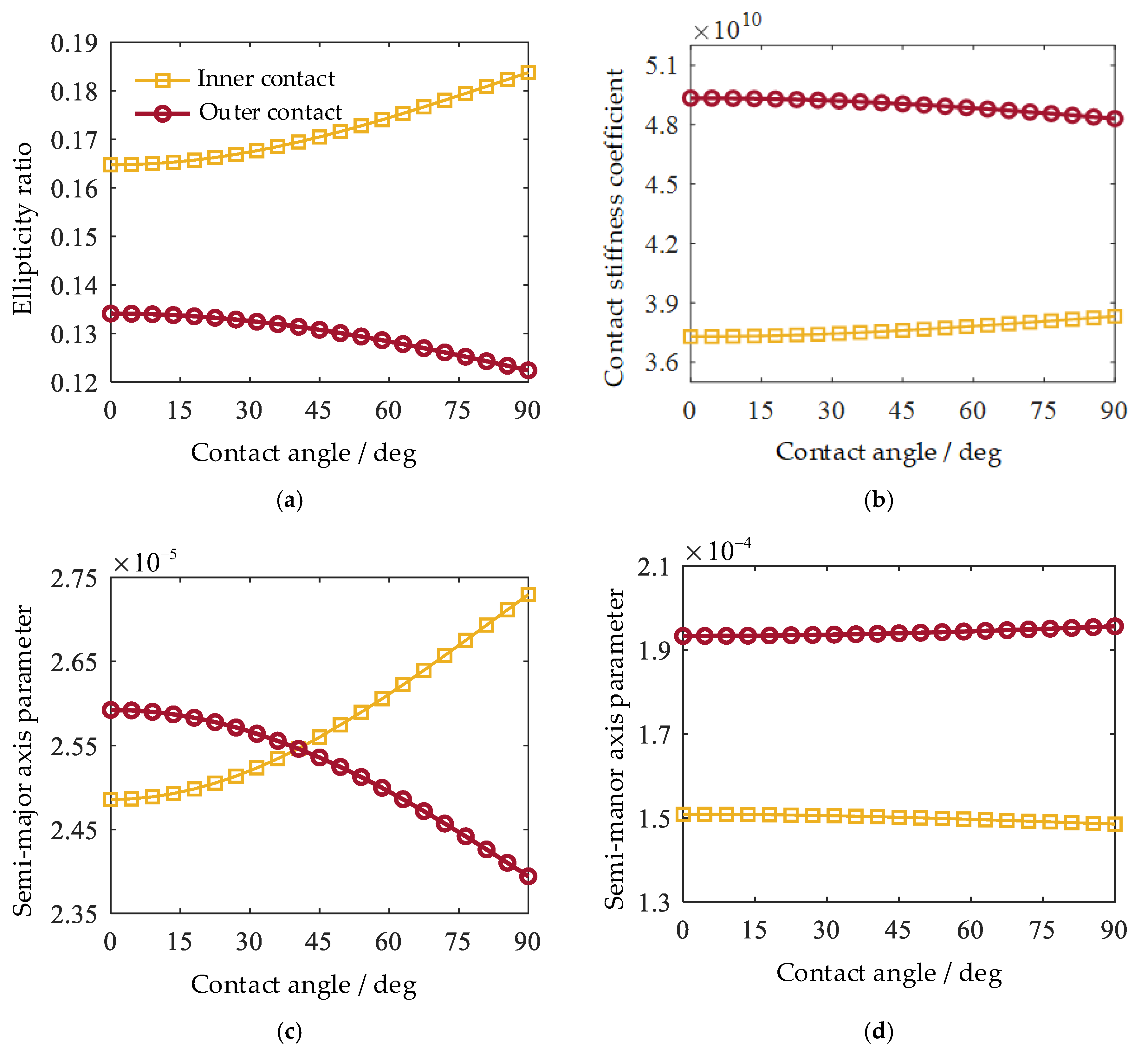
As indicated by Equations (4) and (23)–(25), the contact stiffness as well as the semi-major and semi-minor axis parameters are all functions of the ellipticity ratio k, which itself is directly related to the contact angle in ball bearings. Therefore, to improve the computational efficiency of the dynamic model, a preprocessing step is implemented in which the ellipticity ratio, contact stiffness, semi-major axis parameter, and semi-minor axis parameter corresponding to the contact angles of a specific type of angular contact ball bearing are calculated in advance. During dynamic simulations, these contact parameters are then obtained via interpolation based on the real-time contact angle.
Based on the bearing parameters provided in [
37,
44], the variations of the ellipticity ratio (
k), contact stiffness coefficient (
κ), semi-major axis parameter (
), and semi-minor axis parameter (
) within the contact angle range of [0°, 90°] are plotted in
Figure 4. As shown in the figure, all four parameters exhibit smooth and continuous changes with increasing contact angle, indicating that they are well-suited for interpolation-based retrieval during dynamic simulations.
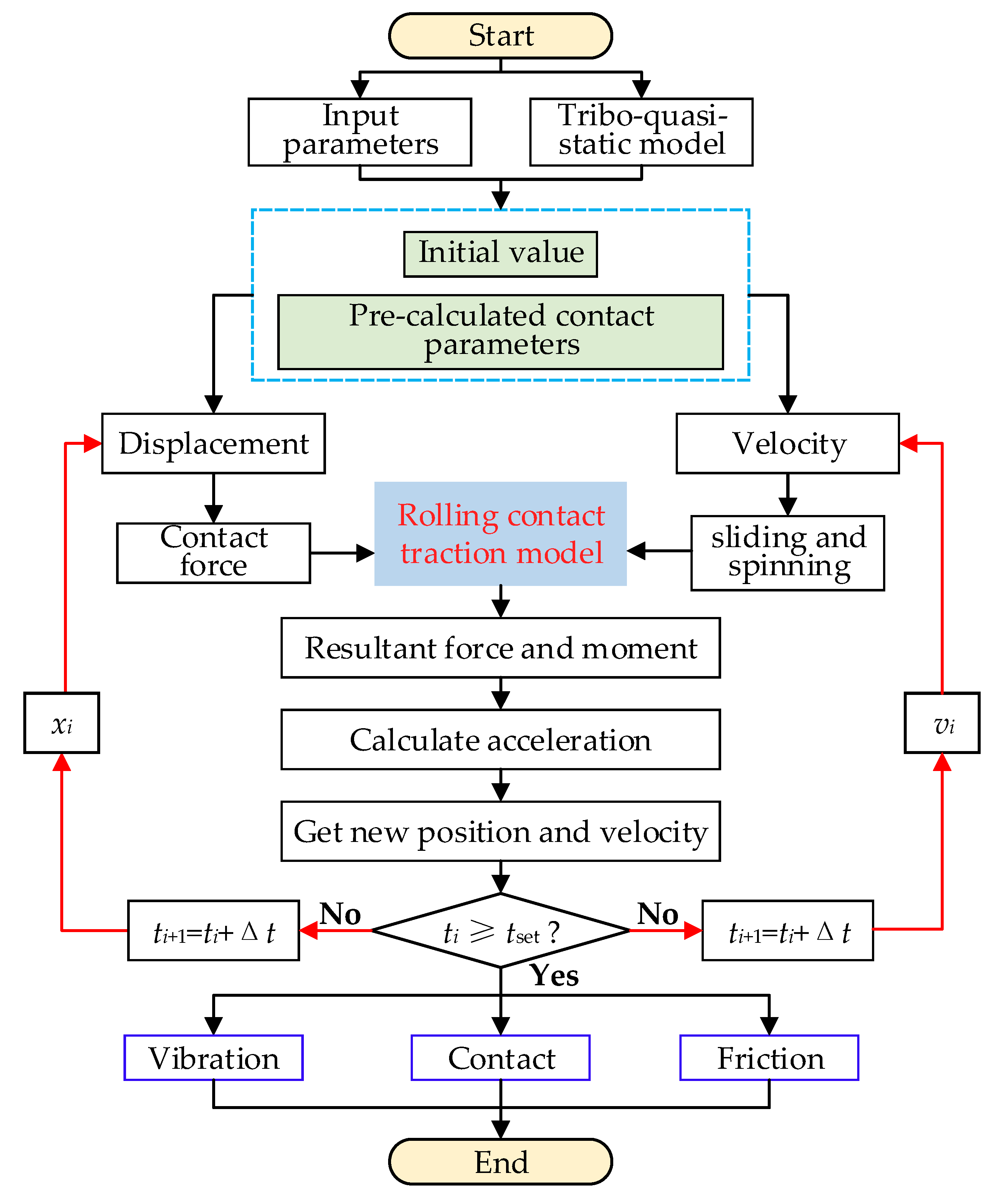
As illustrated in
Figure 5, the solution procedure of the tribo-dynamic model for solid-lubricated ball bearings consists of three main stages:
(1) The first stage is preprocessing, where, based on the given bearing parameters, initial conditions are generated using the quasi-static tribological model proposed in [
19] to enhance the convergence efficiency and enable faster stabilization of the iterative computations.
(2) The second stage involves dynamic computation, during which the contact forces between the balls and raceways are calculated in each iteration step using the positional information of bearing components. The traction forces are then determined from the relative velocity relationships, and all forces are incorporated into the differential equations, which are solved using the fourth-order Runge–Kutta method.
(3) The third stage is postprocessing, where the obtained displacements and velocities are mapped back into the model to derive the time-varying contact angles, contact forces, traction forces, relative velocities, and accelerations—capturing the dynamic response of the bearing system.
Figure 5.
Solving strategy of the tribo-dynamic model.
Figure 5.
Solving strategy of the tribo-dynamic model.
3.2. Model Validation
In this section, the validity of the proposed model is verified using both experimental and theoretical results from the literature. Three models are used for comparison: the J-H quasi-static model [
39], the solid-lubricated quasi-static tribological model [
19,
37], and the proposed tribo-dynamic model. The simulation is conducted under a radial load of 20,000 N, an axial load of 40,000 N, and an inner ring rotational speed of 14,000 r/min.
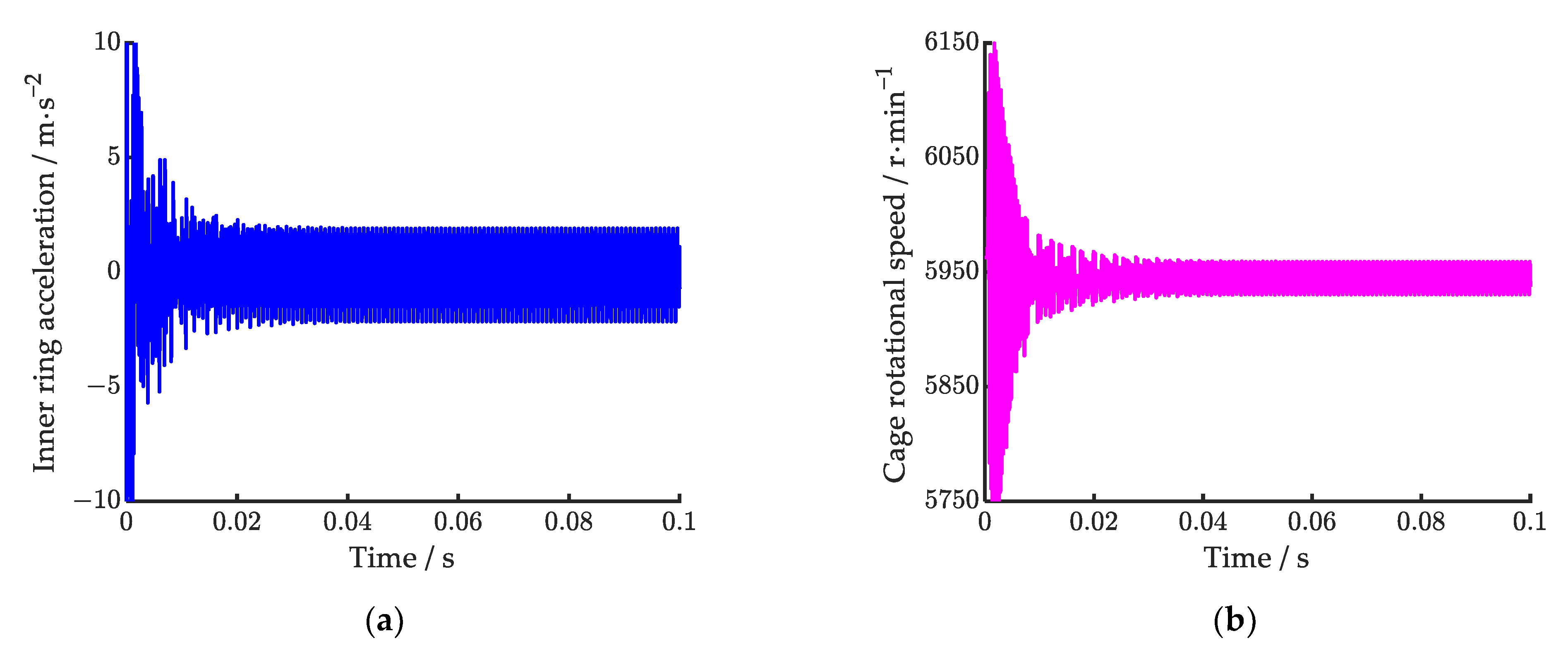
As shown in
Figure 6, the time–domain responses of the inner ring vibration acceleration and cage rotational speed calculated by the proposed model are presented. From
Figure 6a,b, it can be observed that both the vibration acceleration of the inner ring and the rotational speed of the cage become dynamically stable around 0.04 s after initial fluctuations. According to
Figure 6b, it can be calculated that the average rotational speed of the cage is 5943 r/min. Compared to the experimental result reported in [
44], which is 5787 r/min, the relative error of the proposed model is 2.70%. It is worth noting that the theoretically predicted cage speed is slightly higher than the experimental value. This discrepancy is primarily due to the fact that the experimental tests were conducted with the bearing submerged in liquid nitrogen, which introduces fluid resistance to the bearing components—a factor not accounted for in the present model. As a result, the model slightly overestimates the cage speed.
To further verify the accuracy of the proposed model in parametric analysis, a comparative study is conducted between the proposed model, the quasi-static tribological model, and the classical J-H model. As shown in
Table 1, the mean values of some key parameters from different types of models are calculated and compared, where it can be found that the results obtained from the proposed model closely align with those from the quasi-static tribological model, indicating that the latter can effectively provide accurate initial values. In contrast, while the J-H model exhibits relatively large errors in predicting the inner ring displacement and contact angles, it delivers reasonably accurate estimations of the rolling element’s self-rotational and orbital motion, with errors within 10%.
In summary, the proposed solution strategy that combines the quasi-static tribological model with the tribo-dynamic model efficiently enhances the convergence efficiency of the latter. The predicted cage rotational speed deviates from the experimental result by only 2.70% and shows good agreement with the classical J-H quasi-static model. These results collectively demonstrate the effectiveness and accuracy of the proposed modeling approach.
4. Skidding and Over-Skidding Phenomena of Solid-Lubricated ACBBs
This section analyzes the angular contact ball bearing 7218 B as an example, with the bearing parameters shown in
Table 2. To simulate the complete operating process, it is assumed that the outer ring is fixed. During the 0~0.5 s period, the bearing operates at idle speed, with the inner ring rotating at 1000 rpm. Starting from 0.5 s, the inner ring accelerates with an acceleration of 10,000 rpm/s, reaching a constant speed of 10,000 rpm at 1.4 s.
4.1. Motion State of the Bearing During Acceleration Processes
Existing studies have demonstrated that emerging solid coating technologies can achieve ultra-low interfacial friction coefficients, commonly referred to as superlubricity [
45,
46,
47]. To maintain generality in the analysis, this section investigates the skidding mechanism under two representative friction conditions: a low coefficient (0.001) and a conventional value (0.1). The results aim to gain valuable insights into the application of advanced coatings in solid-lubricated ball bearings.
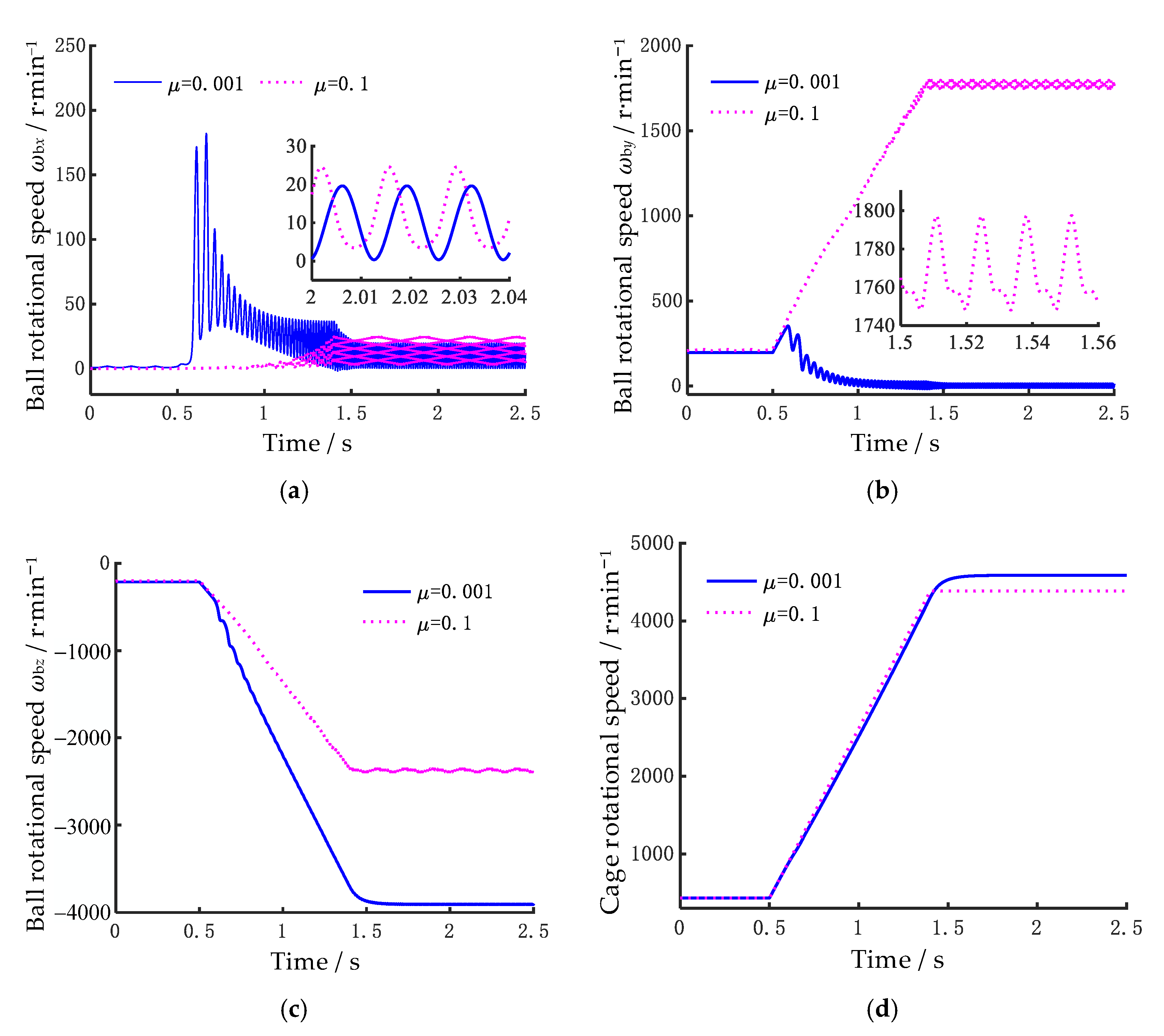
Figure 7 shows the variation of the ball’s self-rotational angular velocity and the cage’s rotational speed over time. From
Figure 7, it can be observed that the ball’s self-rotational angular velocity is significantly influenced by the friction coefficient
μ. When
μ = 0.001, the angular velocity component
ωbx of the ball exhibits considerable fluctuations, while
ωby initially increases rapidly during the acceleration process and then tends to zero. The angular velocity component
ωbz is also significantly higher than the results obtained for
μ = 0.1. The cause of this phenomenon is as follows: according to the principle of conservation of angular momentum, when
ωby decreases, it results in an increase in other angular velocity components. However, since the ball’s yaw angle
β is relatively small, the increase in
ωbx is smaller, while the increase in
ωbz is more substantial. Furthermore, as the rotational speed increases, the amplitude of the fluctuations in the ball’s self-rotational angular velocity also increases significantly. From
Figure 7a,b, it can be seen that once the inner ring reaches a stable rotational speed of 10,000 rpm, the fluctuation period of the ball’s angular velocity is 0.0131 s, which corresponds exactly to the cage’s rotational frequency of 76.45 Hz (4587 rpm). This indicates that the fluctuations in the ball’s rotational speed are primarily caused by the asymmetric loads it experiences during its revolution, which are mainly due to the radial forces. From the cage’s rotational speed in
Figure 7d, it can be observed that the time required for the cage to reach a stable state differs slightly for friction coefficients of 0.001 and 0.1, being approximately 1.77 s and 1.4 s, respectively.
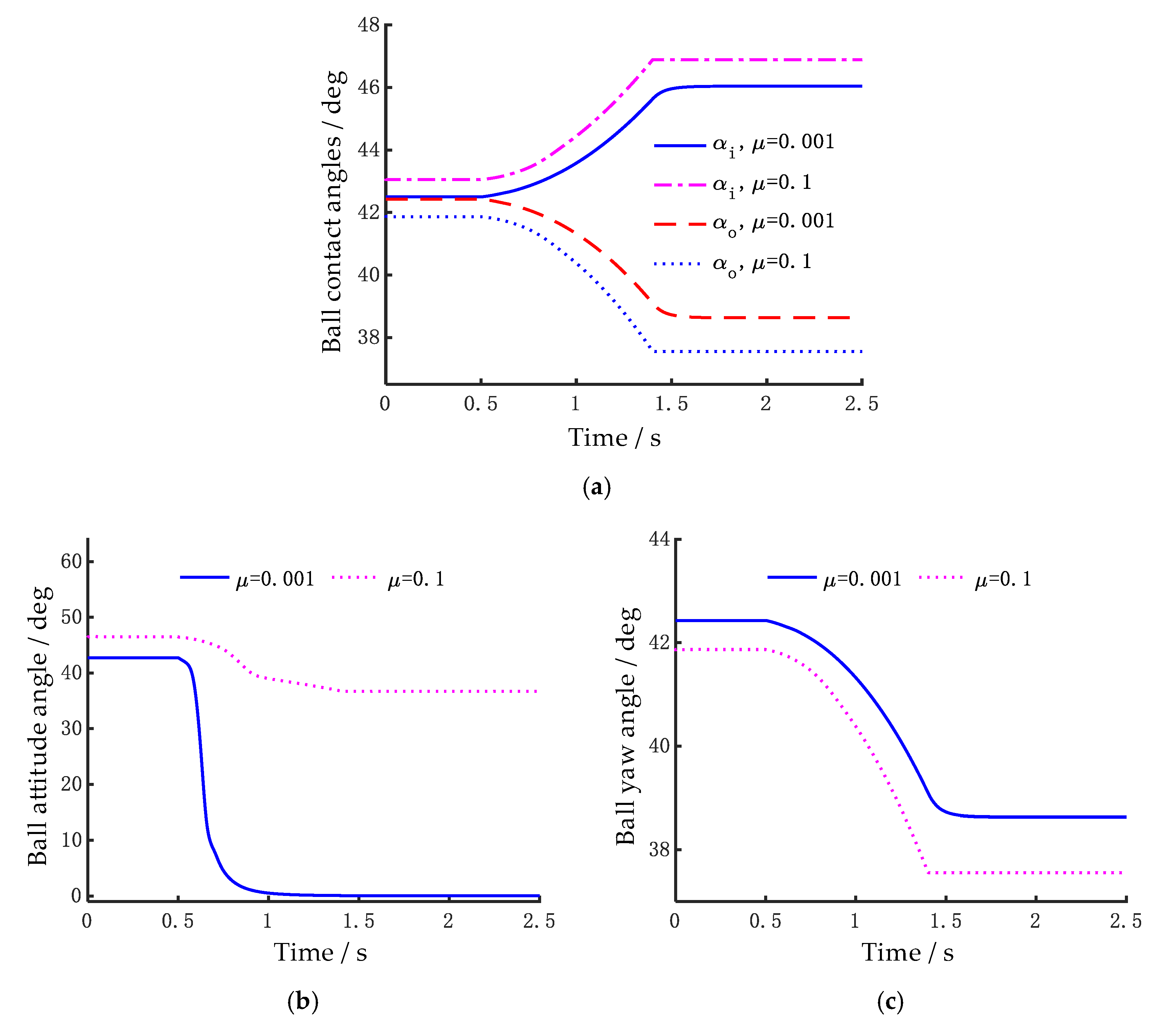
The rotational speed of the ball is closely related to its contact angle. To further explain the cause of the above mentioned phenomenon, the contact angle, attitude angle, and yaw angle are analyzed. As shown in the contact angle analysis results in
Figure 8, it can be found in
Figure 8a that as the inner ring rotational speed increases, the inner contact angle gradually increases, while the outer contact angle gradually decreases. The higher the rotational speed is, the greater the difference between the inner and outer contact angles, which is primarily caused by the centrifugal motion of balls. From the time it takes for the curve to reach equilibrium, it is evident that under low friction coefficients, the rolling element requires a longer acceleration time to reach the final contact state.
The attitude angle and yaw angle indicate the gyroscopic and pivoting motion of the ball, respectively.
Figure 8b,c shows the variation of the attitude angle and yaw angle of the ball during acceleration under two different friction coefficients. It can be observed in
Figure 8b that as the rotational speed increases, the attitude angle of the rolling element initially decreases gradually and stabilizes once the target rotational speed is reached. A key difference is that when the friction coefficient is equal to 0.001, the attitude angle of the rolling element gradually approaches zero. Typically, due to the presence of the contact angle, the self-rotation axis of the rolling element is not aligned with its revolution axis, resulting in a certain attitude angle. This misalignment between the axes generates a gyroscopic torque, leading to the “climbing” phenomenon of the rolling element. However, the reduction in the attitude angle indicates that the self-rotation axis of the rolling element is gradually aligning with the revolution axis, which signals the occurrence of macroscopic slip, namely skidding. From
Figure 8c, it can be observed that when
μ = 0.001, the yaw angle of the ball increases sharply at the initial stage of acceleration and then decreases rapidly. The yaw angle is the primary cause of the pivoting motion of the steel ball, which also explains the significant fluctuations in the
ωbx component of the ball’s self-rotational speed observed in
Figure 7a.
4.2. Skidding Mechanism of Solid-Lubricated ACBBs
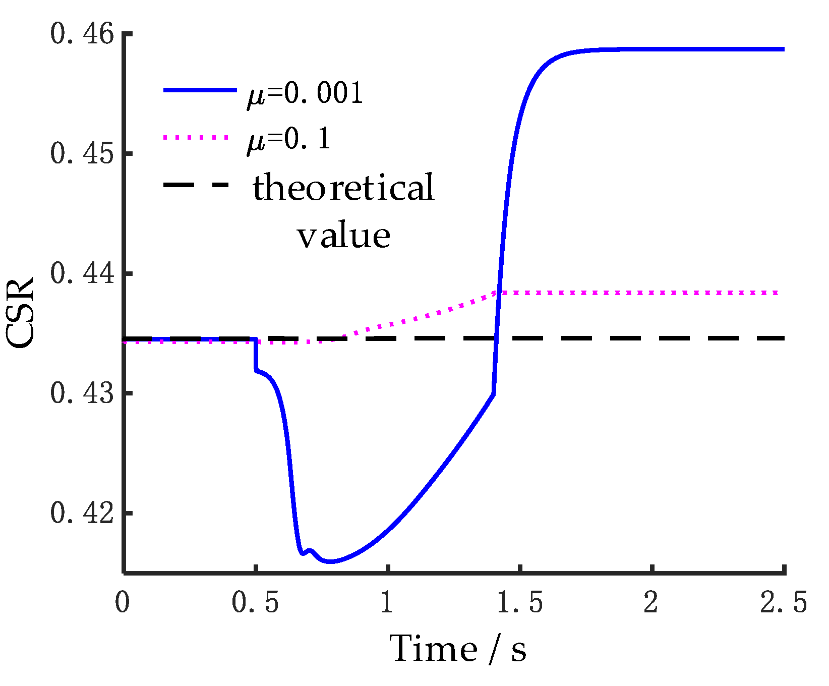
The cage-shaft speed ratio (CSR) serves as a critical indicator for detecting skidding in ball bearings. Reference [
5] investigates the skidding and over-skidding (negative skidding) effects in ball bearings using CSR and highlights that when the actual CSR is lower than the theoretical value derived from the pure rolling assumption, it indicates that the bearing is experiencing skidding. Conversely, when the actual CSR exceeds the theoretical CSR, it suggests that over-skidding is occurring. Typically, under steady low-speed conditions, the balls do not exhibit significant skidding; therefore, the calculated CSR closely aligns with the theoretical value. Based on rolling contact theory, the theoretical speed of the cage can be calculated, as shown in Equation (26), under the assumption that spinning is neglected. During the acceleration phase, due to the low friction coefficient being insufficient to provide adequate traction force for accelerating the rolling elements, skidding occurs. At this point, the CSR will be notably lower than the theoretical value. However, as time progresses, the speed of the balls increases, which in turn drives the cage to accelerate, causing the CSR to rise again, as illustrated in
Figure 9.
Here,
γ’ =
Db/
dm and
Dm is the pitch diameter of the bearing.
Figure 9.
CSR results under different friction coefficients compared with the theoretical value.
Figure 9.
CSR results under different friction coefficients compared with the theoretical value.
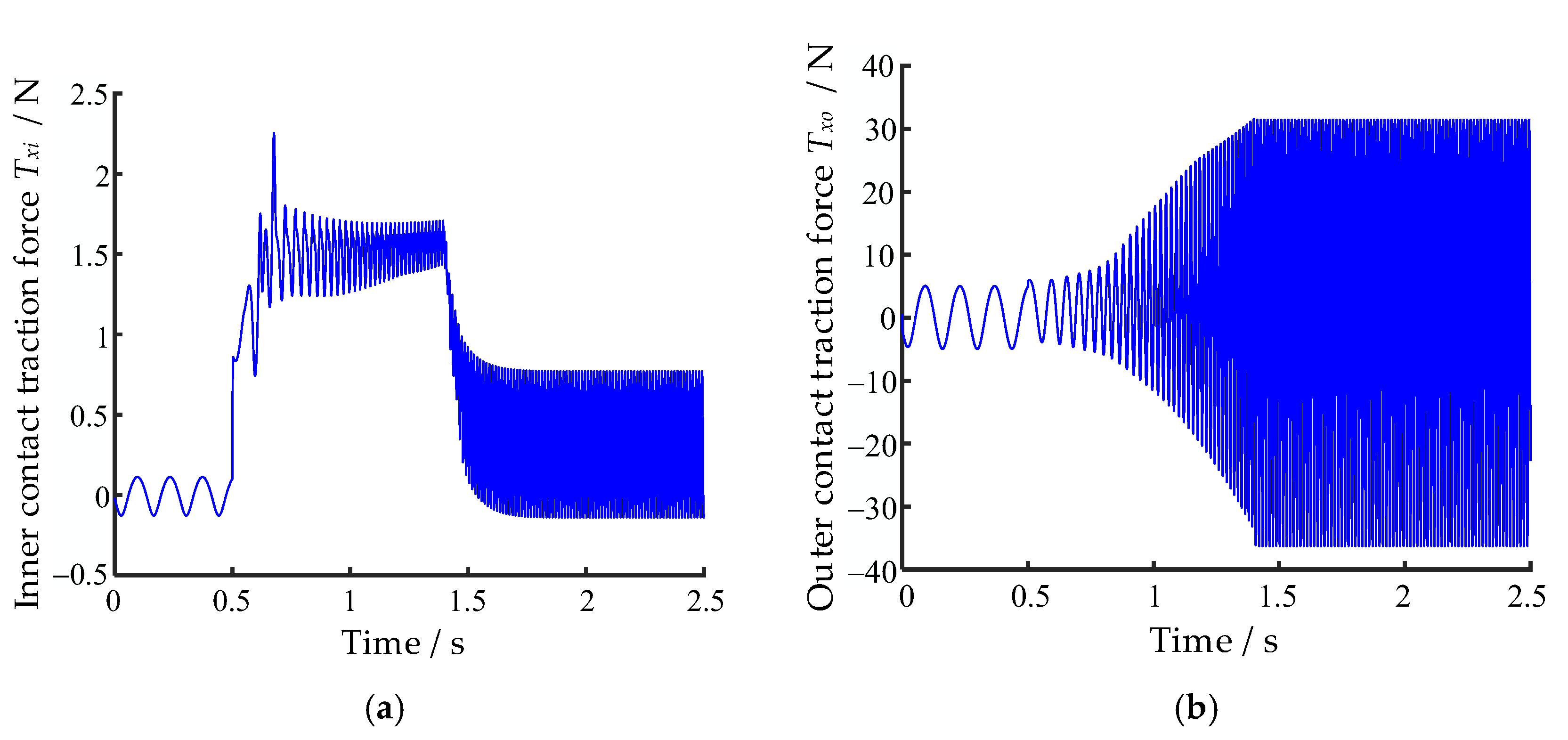
It is noteworthy that during the acceleration process, when the coefficient of friction
μ is equal to 0.1, the CSR does not exhibit a significant decrease but rather gradually increases over time. This phenomenon is primarily influenced by the traction force exerted on the balls. When the traction force is sufficient to overcome the resistance and drive the ball into translational motion, no skidding occurs, and the traction force remains stable. However, at low friction coefficients, the traction force is inadequate to overcome the resistance between the ball and the inner race, as well as the resistance from the cage. As a result, skidding occurs between the ball and the inner raceway, causing the traction force to deviate significantly from the coordinate axis. The variation in traction force on the ball caused by the inner race under two different friction coefficients is shown in
Figure 10.
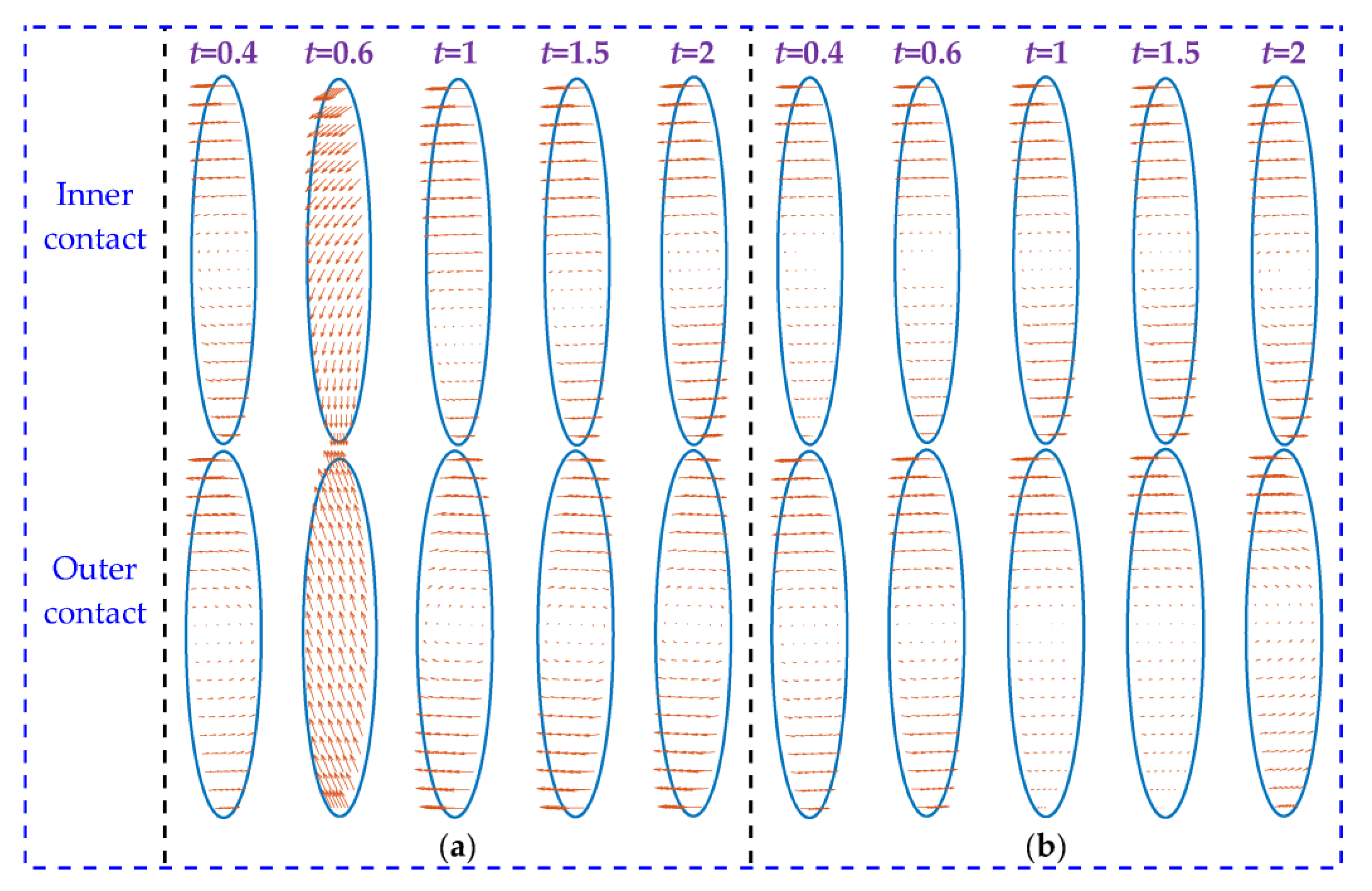
To further observe the sliding and spinning states of the ball, micro-slip diagrams of the contact spots at different time steps were plotted, as shown in
Figure 11. In these diagrams, ellipses represent the contact patches, arrows indicate the sliding direction of the contact particles relative to the raceway within the contact patch, and the blank areas represent regions where the particles exhibit no sliding, indicating a viscous state. It can be observed from
Figure 11 that based on the sliding direction of the particles in the contact patches, the sliding behavior of the ball can be classified into three states: spinning, skidding, and creepage. Under steady rotational speeds (i.e., before 0.5 s and after 1.5 s), no significant skidding occurs, and the rolling elements predominantly exhibit spinning behavior. At low speeds (1000 rpm, before 0.5 s), when the coefficient of friction is 0.1, creepage is observed within the inner contact patches, suggesting that the spinning in the inner contact is relatively small. At this point, the ball tends to exhibit “inner raceway control”. It is important to note that this raceway control phenomenon is quite subtle. In addition, it can be seen that the spinning phenomenon of the ball is more pronounced at both high and low friction coefficients, which indicates that pure rolling motion, in its absolute form, does not exist in practice.
To conclude, the cause of macroscopic skidding is the insufficiency of traction force, which leads to fluctuations in the traction force at the inner contact of the ball when it is greater than zero. However, the continuous positive traction force eventually accelerates the ball to the theoretical speed, causing the inner contact traction force to stabilize and return to a position of steady fluctuation. The direct cause of over-skidding is the significant increase in the rotational speed component ωbz of the ball, primarily attributed to the gyroscopic effect of the ball and the principle of conservation of angular momentum.
5. Skidding Characteristics During the Acceleration Process
The factors influencing skidding in rolling bearings typically include parameters such as lubrication properties [
22,
48], raceway surface roughness [
49], cage flexibility [
20], and loading [
13,
50,
51]. Based on the authors’ previous research [
19], it has been found that under conditions of high radial load and high rotational speed—characteristic of turbopump ball bearings—the skidding and spinning behaviors of the bearing are significantly affected by the friction coefficient at the rolling element–raceway interface and by the axial loading condition. Therefore, this section employs the developed tribo-dynamic model to further investigate the influence of these two factors on the dynamic skidding characteristics of the bearing during rapid acceleration.
5.1. Effects of Coefficient of Friction
As indicated by the analysis in the previous section, the coefficient of friction plays a significant role in the motion state of ball bearings. To further investigate the influence of the coefficient of friction on the skidding and spinning behaviors of the ball, the variations in the sliding and spinning ratios of the ball relative to the inner and outer races under different friction coefficients during operation are presented.
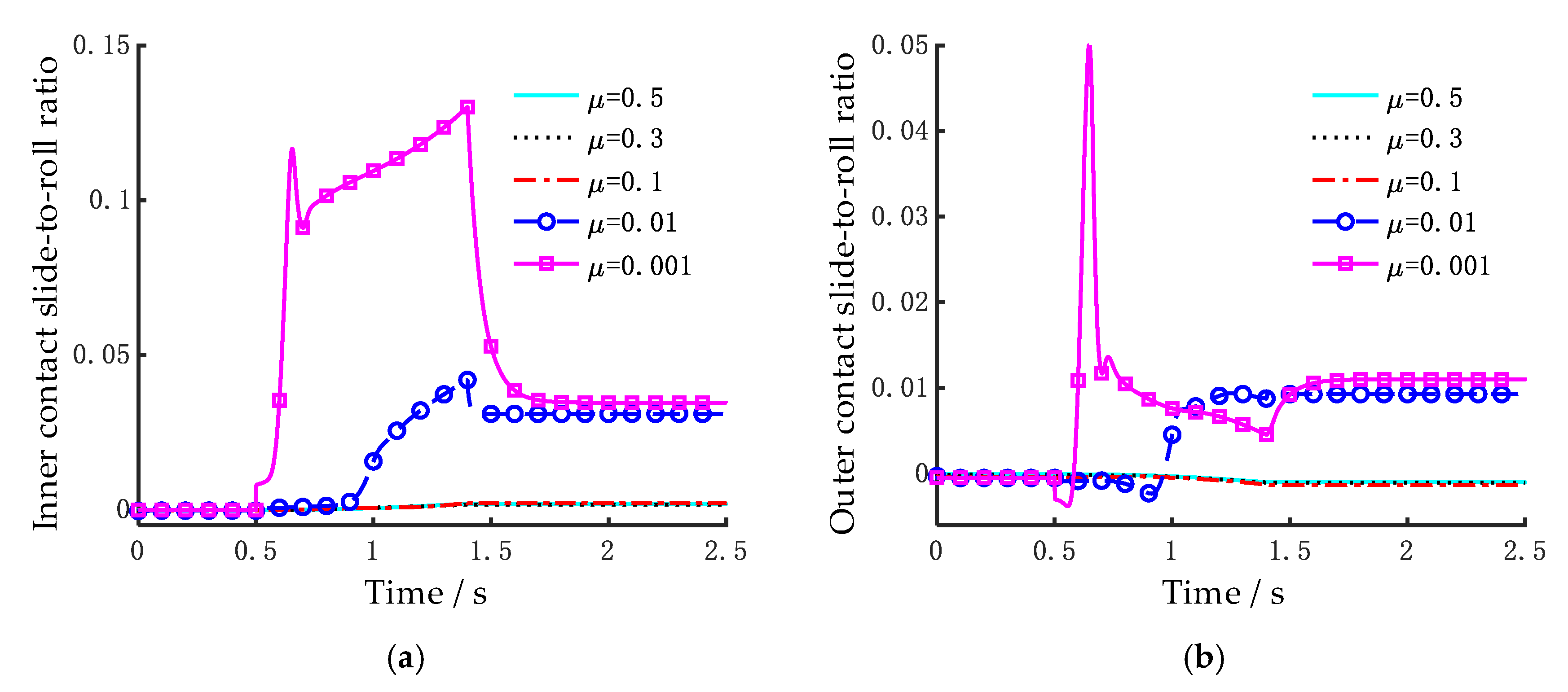
As shown in
Figure 12, under steady low-speed operating conditions, the coefficient of friction has a minimal impact on the slide-to-roll ratios of the bearing. It can be observed that the inner slide-to-roll ratio is generally larger than the outer one. This is because that when the outer race is fixed and the inner race moves, the acceleration of the inner race inevitably leads to an increase in the inner contact sliding rate. As the orbital speed of the rolling elements increases, their sliding rate relative to the inner raceway gradually decreases between 1.4 s and 1.7 s, as shown in
Figure 12a. This change is much more pronounced during macroscopic skidding (under an ultra-low friction coefficient) than during the creepage stage. As a result, it can be inferred that when the coefficient of friction is no lower than 0.1, the frictional force is sufficient to counteract the gyroscopic motion of the rolling elements, which predominantly exhibit creepage and spinning behaviors, resulting in lower sliding rates.
Due to the deviation of the spinning axis of the ball, relative spinning motion exists at the contact spots between the ball and both the inner and outer raceways. As the bearing speed increases, the angular velocity of the ball’s rotation also rises, leading to an increase in the amplitude of the spinning ratio at the inner contact, as illustrated in
Figure 13a. The behavior at the outer contact, however, differs. Influenced by centrifugal effects, the increasing angular velocity of balls during acceleration results in a significant rise in their centrifugal force, which is transferred into contact force at the outer raceway. This enhances the controlling effect of the outer raceway on the balls and consequently suppresses the spinning movement of balls at the outer contact. As a result, with increasing speed, the outer contact spinning ratio amplitude initially rises to a peak and subsequently decreases. When skidding occurs, the spinning ratio at the outer contact undergoes a directional reversal at a certain point in time. According to the kinematic analysis presented in
Figure 8, this reversal is primarily attributed to the sharp reduction in the attitude angle of the ball. Under skidding conditions, the time at which the spinning ratio at the outer contact reaches its peak increases with the coefficient of friction, as shown in
Figure 13b.
5.2. Effects of Insufficient Axial Preload
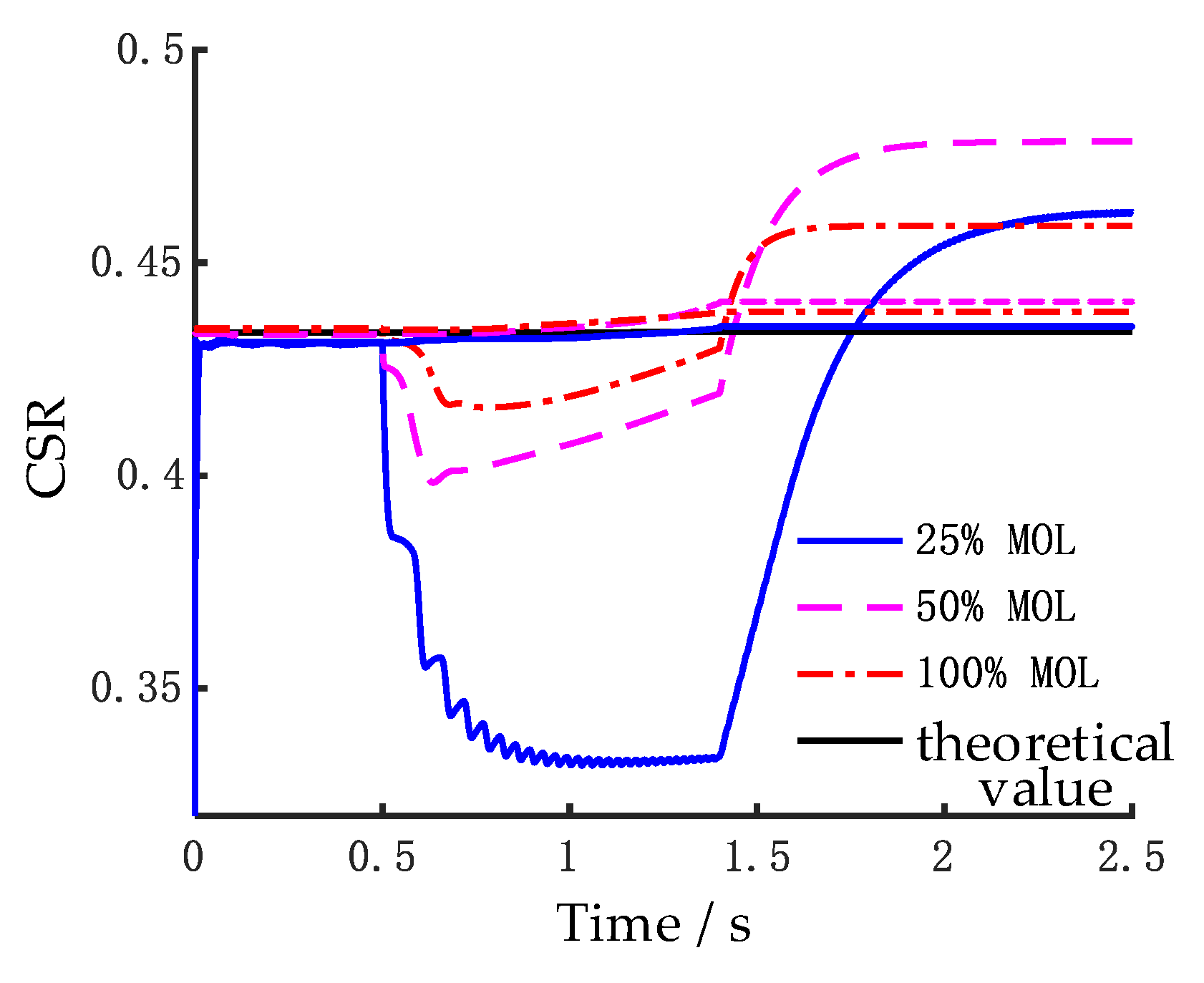
Axial preload can effectively reduce the clearance between balls and raceways, thereby promoting the stable operation of ACBBs. An insufficient axial preload not only increases the rolling-sliding ratio but may also result in significant displacement of the balls in ACBBs during operation, which can in turn induce vibration within the bearing. Therefore, the study of axial preload is of great significance for both the theoretical analysis and engineering applications of ACBBs. To investigate the tribo-dynamic characteristics of ACBBs under insufficient axial preload, this section analyzes two friction coefficients (0.001 and 0.1) under three loading conditions, including 25%, 50%, and 100% of the maximum of loading (MOL). Key parameters including the CSR, ball slide-to-roll ratio, spinning ratio, and vibration acceleration of the inner race are examined.
Insufficient axial preload leads to a reduction in the traction force acting on the balls, thereby prolonging the acceleration time of the cage. This phenomenon is particularly pronounced under low friction conditions, where skidding of the balls occurs. Under the 25% MOL condition, the cage requires more than 2.5 s to reach a steady rotational speed. Furthermore, under severely insufficient axial preload, the CSR exhibits significant fluctuations during the acceleration phase, as shown in
Figure 14. Additionally, when the friction coefficient is 0.1, where only creepage occurs without macroscopic skidding, the influence of the axial preload on the CSR is minimal, and the cage acceleration time is only slightly affected. To further investigate the influence of axial preload under conditions of macroscopic skidding, the slide-to-roll ratio and spinning ratio at a friction coefficient of 0.001 are presented in
Figure 15 and
Figure 16, respectively.
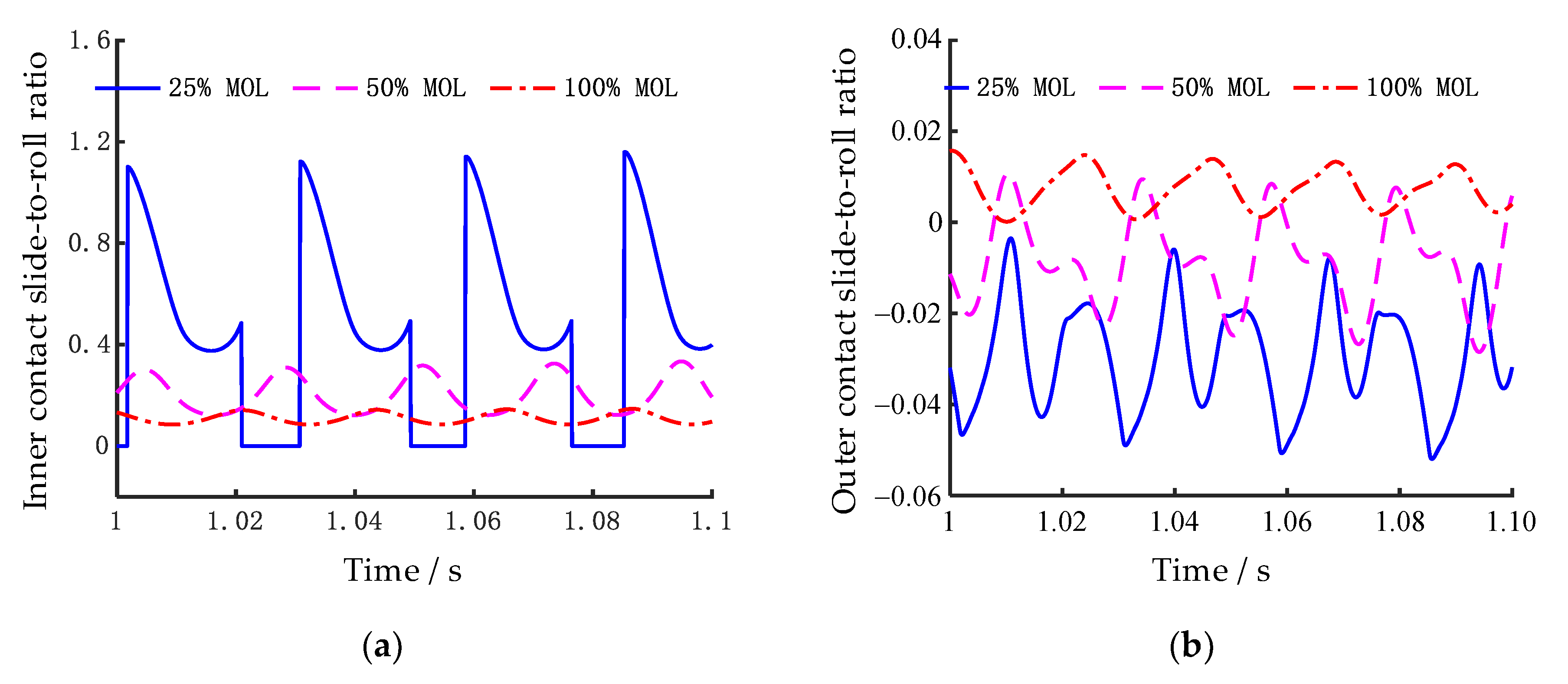
Under operating conditions with applied radial loads, the internal load experienced by the balls varies across different load zones. In the heavily loaded region, due to compression from the inner race, the balls maintain proper contact with both the inner and outer raceways. In the lightly loaded region, however, the reverse displacement of the inner race reduces the contact force between the balls and the inner raceway. When the axial preload is insufficient, excessive internal clearance may cause the balls to lose contact with the inner raceway, resulting in zero traction force and, consequently, a rolling-sliding ratio of zero at the inner contact, as shown in
Figure 15. In addition to the presence of zero rolling-sliding ratio zones,
Figure 15a also reveals that the rolling-sliding ratio exhibits greater fluctuations under low axial preloads. This is primarily attributed to the significant load variation experienced by the balls between the lightly and heavily loaded regions. Due to the influence of centrifugal effects, the balls maintain continuous contact with the outer raceway; thus, the rolling-sliding ratio at the outer contact does not drop to zero. However, as shown in
Figure 15b, greater fluctuations in the outer contact rolling-sliding ratio are also observed under low axial preload conditions.
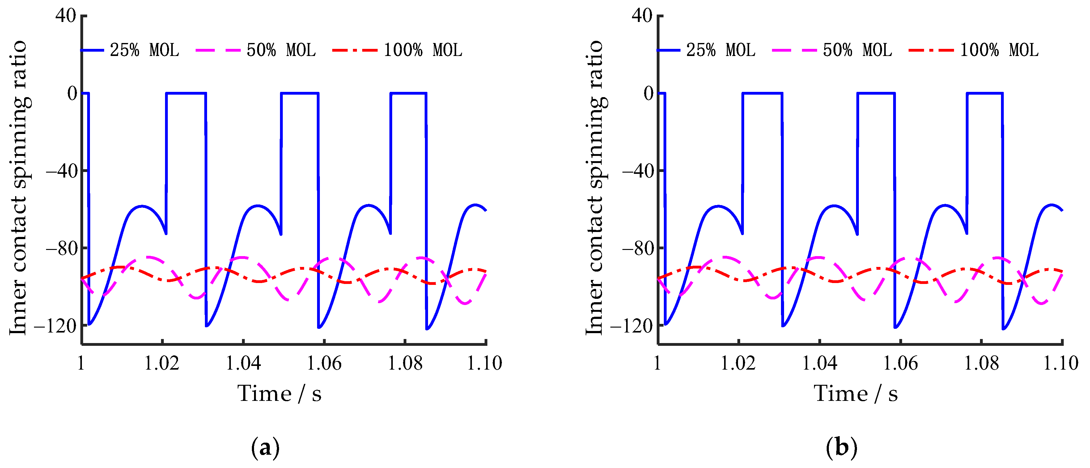
Similar to the sliding characteristics, the spinning ratio of the balls relative to the inner raceway also exhibits zero values, as shown in
Figure 16a. In practice, there exists relative rotational motion between the balls and the inner race; thus, their spinning ratio cannot be truly zero. However, in cases where contact is lost, no spin-induced traction torque is generated, and the spinning ratio is therefore considered zero in the calculations.
Figure 16b shows that the spinning ratio of the balls relative to the outer race decreases with a reduction in axial preload, while the amplitude of its fluctuation increases. This is primarily because lower axial preload results in a longer acceleration time for the cage. At a given time, the rolling elements accelerate more slowly under lower axial preload compared to higher preload conditions. Consequently, their relative spinning ratio with respect to the outer race is also lower. However, due to the greater disparity in loading conditions across different load zones, the spinning ratio exhibits larger fluctuations.
Table 3 presents the maximum vibration acceleration amplitudes of the bearing inner race in the
x-direction during the acceleration phase under different axial preload conditions. As shown in the table, the vibration of the inner race increases significantly with decreasing axial preload. A comparative analysis reveals that the coefficient of friction has a relatively minor effect on the vibration response of the inner race, indicating that the sliding behavior of the balls has limited influence on the macroscopic vibration characteristics of the bearing. The peak acceleration observed under the 25% MOL condition is primarily attributed to the intermittent detachment and impact between the balls and the inner race.
In summary, the occurrence of skidding or over-skidding in solid-lubricated ball bearings during rapid acceleration is primarily due to insufficient traction force or moment transmitted from the raceway to the rolling elements. This insufficiency may result from either an excessively low friction coefficient or inadequate contact force. While conventional tribological systems typically strive to minimize friction, a lower friction coefficient in solid-lubricated ball bearings increases the likelihood of sliding, which can, in turn, accelerate the wear of solid lubricant coatings. Therefore, when developing low-friction solid lubricant coatings in the future, it is crucial to simultaneously enhance their wear resistance to ensure longer service life.
6. Conclusions
In this study, a tribo-dynamic analysis model for solid-lubricated angular contact ball bearings is established. The mechanisms of skidding and over-skidding in such bearings are revealed, and the effects of the friction coefficient and axial preload on skidding characteristics and dynamic behavior are investigated. The main conclusions are summarized as follows:
(1) In the acceleration phase, the sliding behavior of solid-lubricated ACBBs includes skidding, creepage, and spinning, all of which are strongly influenced by the friction coefficient. Skidding is primarily characterized by a significant decrease in the balls’ attitude angle and the rotational speed component ωby.
(2) Skidding is mainly caused by insufficient traction force, which leads to unstable oscillatory motion. Over-skidding is characterized by a cage rotational speed exceeding the theoretical value, primarily due to an excessively large rotational speed component ωbz of the balls, which follows the gyroscopic effect and the principle of conservation of angular momentum.
(3) The influence of the friction coefficient on the slide-to-roll and spinning ratios of the balls is nonlinear. Increasing the friction coefficient effectively suppresses skidding. However, once macroscopic skidding is fully mitigated, further increases in the friction coefficient may cause slight increases in both the slide-to-roll and spinning ratios.
(4) Axial preload plays a critical role in ensuring the stable operation of the bearing. When the axial preload is insufficient, strong impacts may occur between the balls and the inner raceway, which not only increase the slide-to-roll rate but also significantly amplify the vibration response of the bearing.
(5) Considering that solid-lubricated bearings typically incorporate self-lubricating cages, the resulting transfer film can significantly affect the contact conditions between the rolling elements and raceways. To gain deeper insights into the tribology–dynamics coupling mechanism of solid-lubricated ball bearings, future research will focus on both theoretical and experimental investigations that incorporate non-Hertzian contact and transfer film lubrication effects.
Author Contributions
S.Z.: Methodology, Software, Investigation, Formal analysis, Writing—original draft. Y.Z. (Yuhao Zhao): Validation, Project administration, Data curation, Resources, Supervision. J.W.: Conceptualization, Resources. Y.Z. (Yanyang Zi): Data curation, Resources. All authors have read and agreed to the published version of the manuscript.
Funding
This research was supported by the Key R&D Program of Henan Province (No. 231111241300), the Natural Science Foundation of Henan Province (No. 232300420155), the Science & Technology Research Projects of Henan Province (Nos. 242102241021, 252102321137, and 252102210140), and the Key Scientific Research Projects in Higher Education Institutions of Henan Province (No. 24A460020).
Data Availability Statement
The raw data supporting the conclusions of this article will be made available by the authors on request.
Acknowledgments
The authors are grateful for the funding support from the Key R&D Program of Henan Province, the Natural Science Foundation of Henan Province, the Science & Technology Research Projects of Henan Province, and the Key Scientific Research Projects in Higher Education Institutions of Henan Province. The authors also want to express their gratitude to Yuting Ma from Luoyang Normal University for providing language editing.
Conflicts of Interest
The authors declare no conflicts of interest.
Nomenclature
| Symbols | Meaning | Symbols | Meaning |
| O-XYZ | Inertial coordinate system | Mc | Total driving torque exerted on the cage |
| ob-xbybzb | Moving coordinate system | Nb | Total number of balls |
| oi-xiyizi | Inner contact coordinate system | Px/y | Stress of the contact particle |
| oo-xoyozo | Outer contact coordinate system | L | Elastic coefficient of the contact particle |
| op-xpypzp | Cage pocket contact coordinate system | ux/y | Tangential deformation of the contact particle |
| yb | Displacements of the ball along the yb axis | s | Average rolling velocity vector of the contact particle |
| zb | Displacements of the ball along the zb axis | c | Creepage vector of the contact particle |
| ωbx/y/z | Rotational speed components of the ball | Δt | Contact time step |
| αi/o | Inner and outer contact angle | l | Contact path length of the discretized zone |
| A0 | Distance between the raceway curvature center and the ball geometry center | Tx/y | Total traction force over the entire contact patch |
| κ | Contact stiffness | M | Concentrated traction torque vector |
| δ | Contact deformation | rb | Radius of the ball |
| k | Ellipticity of the contact patch | Mi/o/b | Masses of the inner ring/outer ring/ball |
| E’ | Equivalent modulus of elasticity | C | Damping coefficient |
| F | First type of elliptic integrals | K | Stiffness coefficient |
| ε | Second type of elliptic integrals | F | Load act on the inner ring |
| R | Radius of curvature of the raceway | Mc | Resultant torque acting on the cage from the balls |
| θm | Rotational displacement of a ball | Qn | Normal contact force exerted on the ball |
| θc | Rotational displacement of the cage | Ic | Moment of inertia of the cage |
| Δθ | Difference between θm and θc | ωm | Angular velocity of the ball’s revolution |
| rp | Pitch radius of the ball | Mg | Gyroscopic torque of the ball |
| Fcbk | Contact force exerted by the k-th ball on the corresponding cage pocket | Mx/y/z | Traction torques of balls in the respective directions |
| Kcb | Contact stiffness between ball and cage pocket | ωc | Theoretical rotational speed of the cage |
| Ccb | Contact damping coefficient between ball and cage pocket | ωi | Inner ring rotational speed |
| θcl | Clearance angle of the cage pocket | Dm | Pitch diameter of the bearing |
References
- Gupta, P.K.; Gibson, H.G. Real-Time Dynamics Modeling of Cryogenic Ball Bearings with Thermal Coupling. J. Tribol.-Trans. Asme 2021, 143, 031201. [Google Scholar] [CrossRef]
- Gibson, H.; Thom, R.; Moore, C.; Haluck, D. History of space shuttle main engine turbopump bearing testing at the marshall space flight center. In Proceedings of the 57th JANNAF Joint Propulsion Meeting, Colorado Springs, CO, USA, 3–7 May 2010. [Google Scholar]
- Chase, T. Wear Mechanisms Found in Angular Contact Ball Bearings of the SSME’s LOX Turbopump; NASA-TM-103596; NASA: Washington, DC, USA, 1992. [Google Scholar]
- Tu, W.; Shao, Y.; Mechefske, C.K. An analytical model to investigate skidding in rolling element bearings during acceleration. J. Mech. Sci. Technol. 2012, 26, 2451–2458. [Google Scholar] [CrossRef]
- Gao, S.; Chatterton, S.; Naldi, L.; Pennacchi, P. Ball bearing skidding and over-skidding in large-scale angular contact ball bearings: Nonlinear dynamic model with thermal effects and experimental results. Mech. Syst. Signal Process. 2020, 147, 107120. [Google Scholar] [CrossRef]
- El-Thalji, I.; Jantunen, E. Fault analysis of the wear fault development in rolling bearings. Eng. Fail. Anal. 2015, 57, 470–482. [Google Scholar] [CrossRef]
- El-Thalji, I.; Jantunen, E. Dynamic modelling of wear evolution in rolling bearings. Tribol. Int. 2015, 84, 90–99. [Google Scholar] [CrossRef]
- Vencl, A.; Gašić, V.; Stojanović, B. Fault tree analysis of most common rolling bearing tribological failures. In Proceedings of the IOP Conference Series: Materials Science and Engineering, Busan, Republic of Korea, 25–27 August 2017; p. 012048. [Google Scholar]
- Pastukhov, A.; Timashov, E. Procedure for Simulation of Stable Thermal Conductivity of Bearing Assemblies. Adv. Eng. Lett. 2023, 2, 58–63. [Google Scholar] [CrossRef]
- Servais, C.; Bozet, J.L.; Kreit, P.; Guingo, S. Experimental validation of a thermal model of a LOx flooded ball bearing. Tribol. Int. 2014, 80, 71–75. [Google Scholar] [CrossRef]
- Harris, T.A. An Analytical Method to Predict Skidding in High Speed Roller Bearings. Asle Trans. 1966, 9, 229–241. [Google Scholar] [CrossRef]
- Liao, N.T.; Lin, J.F. Ball bearing skidding under radial and axial loads. Mech. Mach. Theory 2002, 37, 91–113. [Google Scholar] [CrossRef]
- Oktaviana, L.; Van-Canh, T.; Hong, S.-W. Skidding analysis of angular contact ball bearing subjected to radial load and angular misalignment. J. Mech. Sci. Technol. 2019, 33, 837–845. [Google Scholar] [CrossRef]
- Jain, S.; Hunt, H. A dynamic model to predict the occurrence of skidding in wind-turbine bearings. In Proceedings of the 9th International Conference on Damage Assessment of Structures, Oxford, UK, 11–13 July 2011; Ouyang, H., Ed.; Journal of Physics Conference Series. IOP Publishing: Bristol, UK, 2011; Volume 305. [Google Scholar]
- Tu, W.; Yu, W.; Shao, Y.; Yu, Y. A nonlinear dynamic vibration model of cylindrical roller bearing considering skidding. Nonlinear Dyn. 2021, 103, 2299–2313. [Google Scholar] [CrossRef]
- Tu, W.; Luo, Y.; Yu, W.; Yu, Y. Investigation of the dynamic local skidding behaviour of rollers in cylindrical roller bearings. Proc. Inst. Mech. Eng. Part K-J. Multi-Body Dyn. 2019, 233, 899–909. [Google Scholar] [CrossRef]
- Han, Q.; Chu, F. Nonlinear dynamic model for skidding behavior of angular contact ball bearings. J. Sound Vib. 2015, 354, 219–235. [Google Scholar] [CrossRef]
- Han, Q.; Li, X.; Chu, F. Skidding behavior of cylindrical roller bearings under time-variable load conditions. Int. J. Mech. Sci. 2018, 135, 203–214. [Google Scholar] [CrossRef]
- Zhao, Y.; Ma, Z.; Zi, Y. Skidding and Spinning Investigation for Dry-lubricated Angular Contact Ball Bearing under Combined Loads. Friction 2023, 11, 1987–2007. [Google Scholar] [CrossRef]
- Liu, Y.; Chen, Z.; Tang, L.; Zhai, W. Skidding dynamic performance of rolling bearing with cage flexibility under accelerating conditions. Mech. Syst. Signal Process. 2021, 150, 107257. [Google Scholar] [CrossRef]
- Gao, S.; Chatterton, S.; Pennacchi, P.; Han, Q.; Chu, F. Skidding and cage whirling of angular contact ball bearings: Kinematic-hertzian contact-thermal-elasto-hydrodynamic model with thermal expansion and experimental validation. Mech. Syst. Signal Process. 2022, 166, 108427. [Google Scholar] [CrossRef]
- Atef, M.M.; Khair-Eldeen, W.; Yan, J.; Nassef, M.G.A. A nonlinear dynamic analysis of skidding behavior in rolling bearings using lubricant traction coefficients and cage flexibility. Tribol. Int. 2024, 197, 109756. [Google Scholar] [CrossRef]
- Liu, Y.; Chen, Z.; Zhai, W.; Lei, Y. Investigation on skidding behavior of a lubricated rolling bearing with fluid–solid-heat coupling effect. Mech. Syst. Signal Process. 2024, 206, 110922. [Google Scholar] [CrossRef]
- Wang, M.; Zhu, L.; Ooi, K.T.; Li, H.; Yan, K.; Hong, J. Friction power loss in ball bearings: Correlation with bearing skidding and cage motion stability. Friction 2025. [Google Scholar] [CrossRef]
- Han, J.; Wang, W.; Zhao, Z. Slip analysis of high speed cylindrical roller bearings. Bearing 2020, 4, 9–14. [Google Scholar] [CrossRef]
- Jing, X.; Cao, H.; Chen, X. Effect of cage slipping on fault characteristic frequencies of aeroengine main-shaft bearings. J. Aerosp. Power 2019, 34, 1145–1152. [Google Scholar] [CrossRef]
- Ma, L.; Jiang, B.; Lu, N.; Xiao, L. Synergistic TransGCN for Aeroengine Bearing Skidding Diagnosis Under Time-Varying Conditions. IEEE Trans. Ind. Inform. 2024, 20, 13936–13946. [Google Scholar] [CrossRef]
- Ma, L.; Jiang, B.; Lu, N.; Xiao, L.; Guo, Q. Angular contact ball bearing skidding mechanism analysis and diagnosis considering flexible rotor characteristics. Mech. Syst. Signal Process. 2024, 207, 110942. [Google Scholar] [CrossRef]
- Ma, L.; Jiang, B.; Lu, N.; Guo, Q.; Ye, Z. Aeroengine Bearing Time-Varying Skidding Assessment With Prior Knowledge-Embedded Dual Feedback Spatial-Temporal GCN. IEEE Trans. Cybern. 2025, 55, 826–839. [Google Scholar] [CrossRef]
- Gao, S.; Han, Q.; Jiang, Z.; Zhang, X.; Pennacchi, P.; Chu, F. Triboelectric based high-precision self-powering cage skidding sensor and application on main bearing of jet engine. Nano Energy 2022, 99, 107387. [Google Scholar] [CrossRef]
- Liu, R.; Li, H.; Wang, P.; Zhu, J.; Zhang, S.; Gao, L.; Yang, Z.; Gu, L.; Cheng, T. Synchronous In-Situ Self-Powered Monitoring Method for Speed and Skidding of High-Speed Bearing Based on Triboelectric Nanogenerator. Adv. Funct. Mater. 2025, 2505831. [Google Scholar] [CrossRef]
- Hailing, J. Second Paper: Analysis of Spin/Roll Conditions and the Frictional-Energy Dissipation in Angular-Contact Thrust Ball Bearings. Proc. Inst. Mech. Eng. 1966, 181, 349–362. [Google Scholar] [CrossRef]
- Kalker, J.J. The analysis of the motion of the balls in an unlubricated angular contact thrust ball bearing. Wear 1968, 12, 3–16. [Google Scholar] [CrossRef]
- Kalker, J.J. Three-Dimensional Elastic Bodies in Rolling Contact; Springer Science & Business Media: Amsterdam, The Netherlands, 2013. [Google Scholar]
- Kalker, J.J. A fast algorithm for the simplified theory of rolling contact. Veh. Syst. Dyn. 1982, 11, 1–13. [Google Scholar] [CrossRef]
- Legrand, E.; Mondier, J.B. Estimation of friction torque in solid-lubricated ball bearings. In Proceedings of the 6th European Space Mechanisms and Tribology Symposium, Zurich, Switzerland, 4–6 October 1995; p. 401. [Google Scholar]
- Zhao, Y.; Zi, Y.; Chen, Z.; Zhang, M.; Zhu, Y.; Yin, J. Power loss investigation of ball bearings considering rolling-sliding contacts. Int. J. Mech. Sci. 2023, 250, 108318. [Google Scholar] [CrossRef]
- Gupta, P.K. Advanced Dynamics of Rolling Elements; Springer Science & Business Media: New York, NY, USA, 2012. [Google Scholar]
- Harris, T.A.; Kotzalas, M.N. Rolling Bearing Analysis: Advanced Concepts of Bearing Technology; CRC Press: Boca Raton, FL, USA, 2007. [Google Scholar]
- Harris, T.A.; Kotzalas, M.N. Rolling Bearing Analysis: Essential Concepts of Bearing Technology; CRC Press: Boca Raton, FL, USA, 2007. [Google Scholar]
- Chen, W.; Ma, Z.; Gao, L.; Li, X.; Pan, J. Quasi-static analysis of thrust-loaded angular contact ball bearings part I: Theoretical formulation. Chin. J. Mech. Eng. 2012, 25, 71–80. [Google Scholar] [CrossRef]
- Haessig, D.A., Jr.; Friedland, B. On the modeling and simulation of friction. J. Dyn. Syst. Meas. Control 1991, 113, 354–362. [Google Scholar] [CrossRef]
- Hamrock, B.J.; Dowson, D. Ball Bearing Lubrication: The Elastohydrodynamics of Elliptical Contacts; Wiley: Hoboken, NJ, USA, 1981. [Google Scholar]
- Zhao, Y.; Chen, Z.; Zi, Y.; Zhang, M.; Tang, T. Dynamic Effect Analysis of Cryogenic Solid-Lubricated Ball Bearings with Geometrical-Frictional Defects. Lubricants 2024, 12, 84. [Google Scholar] [CrossRef]
- Marian, M.; Berman, D.; Rota, A.; Jackson, R.L.; Rosenkranz, A. Layered 2D nanomaterials to tailor friction and wear in machine elements—A review. Adv. Mater. Interfaces 2022, 9, 2101622. [Google Scholar] [CrossRef]
- Meng, Y.; Xu, J.; Jin, Z.; Prakash, B.; Hu, Y. A review of recent advances in tribology. Friction 2020, 8, 221–300. [Google Scholar] [CrossRef]
- Zheng, Z.; Guo, Z.; Liu, W.; Luo, J. Low friction of superslippery and superlubricity: A review. Friction 2023, 11, 1121–1137. [Google Scholar] [CrossRef]
- Meng, F.; Gong, J.; Yang, S.; Huang, L.; Zhao, H.; Tang, X. Study on tribo-dynamic behaviors of rolling bearing-rotor system based on neural network. Tribol. Int. 2021, 156, 106829. [Google Scholar] [CrossRef]
- Wang, Y.; Wang, W.; Zhang, S.; Zhao, Z. Effects of raceway surface roughness in an angular contact ball bearing. Mech. Mach. Theory 2018, 121, 198–212. [Google Scholar] [CrossRef]
- Xu, T.; Xu, G.; Zhang, Q.; Hua, C.; Tan, H.; Zhang, S.; Luo, A. A preload analytical method for ball bearings utilising bearing skidding criterion. Tribol. Int. 2013, 67, 44–50. [Google Scholar] [CrossRef]
- Fang, B.; Zhang, J.; Wan, S.; Hong, J. Determination of Optimum Preload Considering the Skidding and Thermal Characteristic of High-Speed Angular Contact Ball Bearing. J. Mech. Des. 2018, 140, 053301. [Google Scholar] [CrossRef]
Figure 1.
Coordinate systems of the ACBB: (a) inertia and moving coordinate systems; (b) contact coordinate systems of the ball; (c) ball–cage contact coordinate system.
Figure 1.
Coordinate systems of the ACBB: (a) inertia and moving coordinate systems; (b) contact coordinate systems of the ball; (c) ball–cage contact coordinate system.
Figure 2.
The simplified rolling contact model: (a) the creepage phenomenon; (b) discretization method of the contact region.
Figure 2.
The simplified rolling contact model: (a) the creepage phenomenon; (b) discretization method of the contact region.
Figure 3.
Diagram of the dynamic model of the system.
Figure 3.
Diagram of the dynamic model of the system.
Figure 4.
Contact parameters varying with contact angle: (a) ellipticity ratio; (b) contact stiffness coefficient; (c) semi-major axis parameter; (d) semi-minor axis parameter.
Figure 4.
Contact parameters varying with contact angle: (a) ellipticity ratio; (b) contact stiffness coefficient; (c) semi-major axis parameter; (d) semi-minor axis parameter.
Figure 6.
Dynamic responses of the proposed model: (a) inner ring vibration acceleration; (b) cage rotational speed.
Figure 6.
Dynamic responses of the proposed model: (a) inner ring vibration acceleration; (b) cage rotational speed.
Figure 7.
Rotational speeds of the ball and the cage: (a) ball rotational component ωbx; (b) ball rotational component ωby; (c) ball rotational component ωbz; (d) cage rotational speed.
Figure 7.
Rotational speeds of the ball and the cage: (a) ball rotational component ωbx; (b) ball rotational component ωby; (c) ball rotational component ωbz; (d) cage rotational speed.
Figure 8.
Time-varying curves of contact, attitude, and yaw angles of the ball under different friction coefficients: (a) contact angles; (b) attitude angle; (c) yaw angle.
Figure 8.
Time-varying curves of contact, attitude, and yaw angles of the ball under different friction coefficients: (a) contact angles; (b) attitude angle; (c) yaw angle.
Figure 10.
Traction forces of the ball from the inner and outer raceway: (a) inner traction force; (b) outer traction force.
Figure 10.
Traction forces of the ball from the inner and outer raceway: (a) inner traction force; (b) outer traction force.
Figure 11.
Micro-slip distribution of particle in contact spots under different coefficients of friction: (a) μ = 0.001; (b) μ = 0.1.
Figure 11.
Micro-slip distribution of particle in contact spots under different coefficients of friction: (a) μ = 0.001; (b) μ = 0.1.
Figure 12.
Effects of friction coefficient on the slide-to-roll ratio: (a) inner contact; (b) outer contact.
Figure 12.
Effects of friction coefficient on the slide-to-roll ratio: (a) inner contact; (b) outer contact.
Figure 13.
Effects of friction coefficient on the spinning ratio: (a) inner contact; (b) outer contact.
Figure 13.
Effects of friction coefficient on the spinning ratio: (a) inner contact; (b) outer contact.
Figure 14.
CSR results under different axial preloads.
Figure 14.
CSR results under different axial preloads.
Figure 15.
Rolling-sliding ratio results under different axial preloads: (a) inner contact rolling-sliding ratio; (b) outer contact rolling-sliding ratio.
Figure 15.
Rolling-sliding ratio results under different axial preloads: (a) inner contact rolling-sliding ratio; (b) outer contact rolling-sliding ratio.
Figure 16.
Spinning ratio results under different axial preloads: (a) inner contact spinning ratio; (b) outer contact spinning ratio.
Figure 16.
Spinning ratio results under different axial preloads: (a) inner contact spinning ratio; (b) outer contact spinning ratio.
Table 1.
Results of different theoretical models.
Table 1.
Results of different theoretical models.
| Items | J-H Model
(Outer Raceway Control) | Quasi-Static Tribological Model | Proposed Tribo-Dynamic Model |
|---|
| Inner ring radial displacement xi/m | 2.2070 × 10⁻⁵ | 3.0777 × 10⁻⁵ | 2.8952 × 10⁻⁵ |
| Inner ring axial displacement zi/m | 1.7693 × 10⁻⁴ | 1.3827 × 10⁻⁴ | 1.4079 × 10⁻⁴ |
| Internal contact angle αi/deg | 26.5825 | 29.2404 | 29.1706 |
| External contact angle αo/deg | 19.8722 | 14.9111 | 15.1209 |
| Attitude angle α/deg | 16.8767 | 14.6980 | 15.3475 |
| Yaw angle β/deg | 0 | 0.0874 | 0.1203 |
| Ball rotation component ωbx/(r/min) | 0 | 57.6353 | 79.0204 |
| Ball rotation component ωby/(r/min) | 11,129 | 9877 | 10,287 |
| Ball rotation component ωbz/(r/min) | 36,693 | 37,727 | 37,491 |
| Ball orbital rotation ωbm/(r/min) | 5896 | 5963 | 5943 |
Table 2.
Parameters of the 7218B bearing.
Table 2.
Parameters of the 7218B bearing.
| Parameters | Values |
|---|
| Number of balls Nb | 16 |
| Ball diameter Db/mm | 22.23 |
| Inner ring diameter Di/mm | 102.79 |
| Outer ring diameter Do/mm | 19.8722 |
| Contact angle α0/deg | 40 |
| Young’s modulus E/GPa | 206 |
| Poisson’s ratio υ | 0.3 |
| Density ρ/kg∙m−3 | 7800 |
Table 3.
Maximum acceleration amplitudes of the inner ring under different axial preloads.
Table 3.
Maximum acceleration amplitudes of the inner ring under different axial preloads.
| Axial Preload | Acceleration Amplitude |
|---|
| μ = 0.001 | μ = 0.1 |
|---|
| 25% MOL | 11.620 | 10.498 |
| 50% MOL | 0.042 | 1.088 |
| 100% MOL | 0.022 | 0.141 |
| Disclaimer/Publisher’s Note: The statements, opinions and data contained in all publications are solely those of the individual author(s) and contributor(s) and not of MDPI and/or the editor(s). MDPI and/or the editor(s) disclaim responsibility for any injury to people or property resulting from any ideas, methods, instructions or products referred to in the content. |
© 2025 by the authors. Licensee MDPI, Basel, Switzerland. This article is an open access article distributed under the terms and conditions of the Creative Commons Attribution (CC BY) license (https://creativecommons.org/licenses/by/4.0/).


