Article

An Approach for Predicting the Vibro-Impact Behavior of Angular Contact Ball Bearing Considering Variable Clearance

1
Graduate School of Technology and Management, Kyung Hee University, Yongin-si 17104, Republic of Korea
2
School of Chemistry and Chemical Engineering, Nanjing University of Science and Technology, Nanjing 210094, China
3
School of Mechanical Engineering, Nanjing University of Science and Technology, Nanjing 210094, China
*
Author to whom correspondence should be addressed.
Lubricants 2025, 13(5), 216; https://doi.org/10.3390/lubricants13050216
Submission received: 29 March 2025 / Revised: 10 May 2025 / Accepted: 12 May 2025 / Published: 14 May 2025
(This article belongs to the Special Issue Advances in Lubricated Bearings, 2nd Edition)

Abstract

:
This work develops a comprehensive analysis method to examine the nonlinear dynamic response of angular contact ball bearings (ACBBs) with variable clearance. Based on the elastic contact theory and friction principle, the nonlinear contact-impact behavior of the ACBB is systematically investigated. A multibody dynamics model incorporating three-dimensional clearance effects is developed. First, the nonlinear vibro-impact dynamics model of the ACBB is presented considering the influence of variable clearance. Second, the kinematic analysis of the ACBB with clearance is planned, and performance tests are performed under variable conditions, which demonstrate the effectiveness of the proposed method. Furthermore, a comparative analysis of a numerical simulation of the ACBBs with variable clearance is performed. The results show that the increase in rotation speed and external load would cause the high-frequency contact impact between ball and raceway. The decline of the deviation ratio for the cage’s mass center velocity illustrates that the motion trajectory of ACBB would be irregular.

1. Introduction

The stability of ACBBs has emerged as a critical focus in rotary machinery dynamics, particularly due to its direct correlation with the kinematic performance of systems. The inevitable presence of clearance within these bearings demonstrates nonlinear dependency on multiple design parameters, including rotational velocity, axial preload, and lubrication conditions [1,2,3,4]. An increase in external load has obvious effects on the loading region, and the growth in the motion state could enhance the vibro-impact feature of contact elements. Meanwhile, the variation in the motion state would improve the dynamic complexity of ball bearings with loads. In particular, the dynamic stability of ACBBs can be affected under various motion states. Thus, numerical analysis methods for elastic vibration characteristics in ball bearings are key to finding the trajectory of variable clearance [5,6,7,8]. The contact friction characteristics at contact interfaces induce morphological evolution of surface topography, while the accurate characterization of dynamic responses (including energy dissipation and rebound phenomena) poses significant challenges in ball bearing system modeling and dynamic analysis.
Modeling methods and numerical solution approaches have attracted the attention of researchers [9,10,11]. Liu et al. [12,13] established a coupled model of ball bearings using the finite element approach. Five degrees of freedom were considered, and the Runge–Kutta approach was used for the solution of coupled dynamic equations. As the supported components in flywheel rotor systems, the dynamic force of ball bearings with clearance was studied by Zhang et al. [14]. The elastic deformation transmissibility caused by contact was expressed by Hertz’s contact theory, and the effects of unbalanced mass and fit clearance were discussed. Considering the influence of assembly clearance, Liu et al. [15] proposed the vibration analysis approach for angular contact ball bearings, which was validated using a dynamic experiment. The results showed that a reasonable clearance value could relieve the vibration phenomenon of ball bearings. Prashant et al. [16] presented a mathematical method for conducting the nonlinear vibration analysis of ball bearings. Hertz’s contact deformation theory was employed to show the nonlinear contact force between the ball and the raceway, and the vibration response was related to the clearance value and ball number. The effects of thermal deformation were introduced into the dynamic equations of angular contact ball bearings by Gao et al. [17]. The results showed that surface deformation can cause oscillation of kinematic behavior, which should be considered in the simulation and design. However, the changes in the relative positions of ball bearing elements are always analyzed using Hertz’s contact theory, which cannot reveal the dissipative characteristics of contact elements.
Meanwhile, the discussion of contact-impact characteristics is always the main content of the clearance model [18,19,20,21]. Mohamed et al. [22] proposed a contact force model with a low coefficient for representing the contact features of balls, and the compliance model with micro-deformation could reflect the process of energy conversion. Wang et al. [23] conducted a comparative analysis of contact-force models, and energy loss was introduced into the simulation model. The results showed that Hertz’s contact-force model could not describe the viscosity of the contact process, and the L-N (Lankarani–Nikravesh) contact-force model had an advantage in describing the micro-deformation phenomenon. According to elastic deformation theory, Qi et al. [24] investigated contact analysis in ball bearings. The position and penetration caused by impact were listed, and friction effects were also revealed. The continuous contact law could display the viscous damping feature of contact elements. The viscous damping term was added by Hu and Guo to represent the energy transmission [25]. Then, a case study demonstrated the effectiveness and accuracy of the proposed model. Moreover, Tian et al. [26,27] presented a new contact-force model considering lubrication characteristics, and the elastohydrodynamic response was expressed by the flexible spherical joint, which provides a guide for studying the contact-force model. Bai et al. [28,29] expanded the contact-force model with the nonlinear stiffness coefficient. The hybrid contact-force model could be satisfied with the condition of non-conformal contact, and the physical nature of energy transferred during the contact process was also represented clearly. Although the above contact-force model can show the nonlinear dynamic behavior of clearance joints, there is not a suitable model for revealing the ellipticity characteristics of ball bearings during the impact. Therefore, it is necessary to search for a modeling method of nonlinear vibro-impact characteristics in angular contact ball bearings.
The outline of this work is as follows. The work first develops a modeling approach for angular contact ball bearings based on the clearance between the ball, cage, and raceway. In line with all dynamic analysis models, the scheme assumes the existence of elastic contact deformation such that it is thought of as the reason for the contact impact for variable clearance (i.e., the different states that appear in the motion are assumed). The scheme predicts the effective properties of the contact-impact process using the force model in the normal and tangential directions. However, the calculation of this method requires a solution similar to parallel iterative computing in multibody system dynamics, and this is a computational challenge. Based on the Newton–Raphson method, a solution strategy for the dynamic equations is developed, which is demonstrated through a dynamic experiment test. Moreover, it predicts the vibration response and motion stability of a ball bearing with variable clearance. Finally, the proposed method is employed to compute the nonlinear vibro-impact characteristics of the ball bearing and estimate motion stability under different operation conditions.

2. Theoretical Analysis of Ball Bearings

With atrocious working conditions taken into account, the movement inside angular contact ball bearings is complicated. The high-frequency collision phenomenon would cause the contact force and wear in the surface of a solid, and the value of clearance can be changed. Additionally, contact and friction can cause the appearance of vibro-impact characteristics, and the nonlinear dynamic response is also expanded. As a relatively complete approach to analyzing contact characteristics, Hertz’s contact theory describes only the purely elastic deformation during the contact-impact process, without considering the energy loss in the calculation [30,31]. At the same time, it struggles to represent the nonlinear dynamic response of an angular contact ball bearing. Therefore, a new dynamic analysis model for an angular contact ball bearing with variable clearance should be established, suitable for simulating both stable and unstable states.

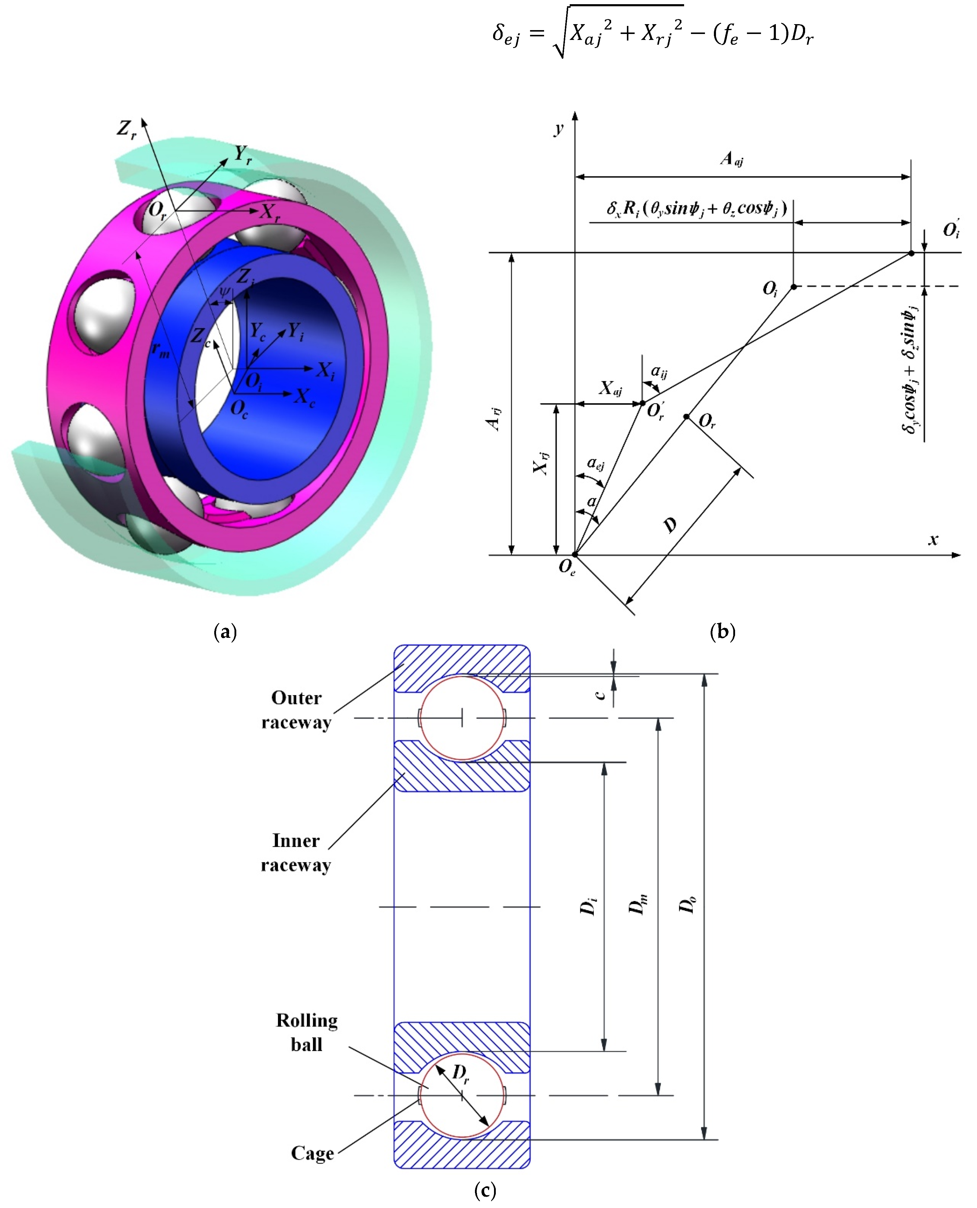
2.1. Geometric Relationship of Coordinate Systems

The relationship between displacement and deformation for angular contact ball bearings is plotted in Figure 1. Or and O r are the initial and final positions of the ball center, respectively. Oe is the fixed position of the outer raceway groove curvature center. Oi and O i represent the initial and final positions of the inner raceway center, respectively. D denotes displacement of the groove curvature center in raceways. α denotes the initial contact angle, and φ j is the angular position of the ball. θ y and θ z are the angular displacement of the inner circle around the y- and z-axes, respectively. δ x , δ y , and δ z are the displacement of the inner raceway in the x, y, and z directions, respectively. X a j and X r j are the displacement between the ball center and outer raceway groove curvature center in the axial and radial directions, respectively [32,33]. Then, A a j and A r j are the displacement of the groove curvature center in the axial and radial directions, respectively, which is written as:
A a j = D s i n α + δ x + R i θ y s i n φ j + θ z c o s φ j
A r j = D c o s α + δ y c o s φ j + δ z s i n φ j
R i = 0.5 D m + f i 0.5 D r c o s α
R e = 0.5 D m + f e 0.5 D r c o s α
D = f i + f e 1 D r
where Dm is the pitch diameter, Dr is the ball diameter, and fi and fe are the coefficients of the groove curvature for the inner and outer raceways, respectively.
The relative motion of the ball and raceway is easy to find in a ball bearing with deformation caused by contact and impact. The relative positions of a ball in the raceway are written as:
δ i j = A a j X a j 2 + A r j X r j 2 f i 1 D r
δ e j = X a j 2 + X r j 2 f e 1 D r

2.2. Equilibrium Constraint and Dynamic Motion

To analyze the effects of contact-impact features on high-frequency vibration between the ball and raceway, as well as low-frequency vibration, the equilibrium constraint is used to limit the motion of the ball [34,35]. At every time step, the dynamic differential motion of the ball center in the axial and radial directions can be described by the support force, as shown in Figure 2. According to the equilibrium constraint equations, the position of the ball center should be given in the coordinate systems, which is represented as
Q n i j s i n α i j Q n e j s i n α e j Q f i j c o s α i j + Q f e j c o s α e j = 0
Q n i j c o s α i j Q n e j c o s α e j + F e j Q f i j s i n α i j + Q f e j s i n α e j = 0
where Q n i j and Q n e j represent the contact force between the ball and raceway, respectively; i and e are inner and outer raceways, respectively; Q f i j and Q f e j are the friction force in the tangential direction; α i j and α e j are contact angle of inner and outer; and F e j denotes the centrifugal force of the ball.
According to the distribution of support force, the inner raceway center position has three degrees of freedom, and the position can be obtained using the equilibrium equation, which is given as
F x j = 1 N Q n i j s i n α i j Q f i j c o s α i j = 0
F y j = 1 N Q n i j c o s α i j + Q f i j s i n α i j s i n φ j = 0
F z j = 1 N Q n i j c o s α i j + Q f i j s i n α i j c o s φ j = 0
M g j = J ω r ω i j ω m ω i j ω i 2 s i n β
where F x , F y , and F z are the external loads (F) on the inner raceway, M g j is the gyroscopic moment, and N is the number of balls.
The differential equation can present the position of the ball center in the circumferential direction, which is written as
m r r φ ¨ = F φ
I r ω ˙ r x = M r x I r ω ˙ r y I r ω r z φ ˙ j = M r y I r ω ˙ r z I r ω r y φ ˙ j = M r z
Then, the radius of the ball center trajectory r is given as
r = X r j + R e
where m r is the mass of the ball, F φ denotes the applied force of the ball in the circumferential direction, I r represents the inertia moment of the ball, and M r and ω r are the total moment and angular velocity of the ball, respectively.
The motion equation and moment of momentum for a cage are obtained as
m c x ¨ c = F c x m c y ¨ c = F c y m c z ¨ c = F c z
I c x ω ˙ c x + I c z I c y = ω c y ω c z = M c x I c y ω ˙ c y + I c x I c z = ω c z ω c x = M c y I c z ω ˙ c z + I c y I c x = ω c x ω c y = M c z
where m c is the mass of the cage, I c is the inertia moment of the cage, and F c and M c are the total applied force and total moment of momentum, respectively.

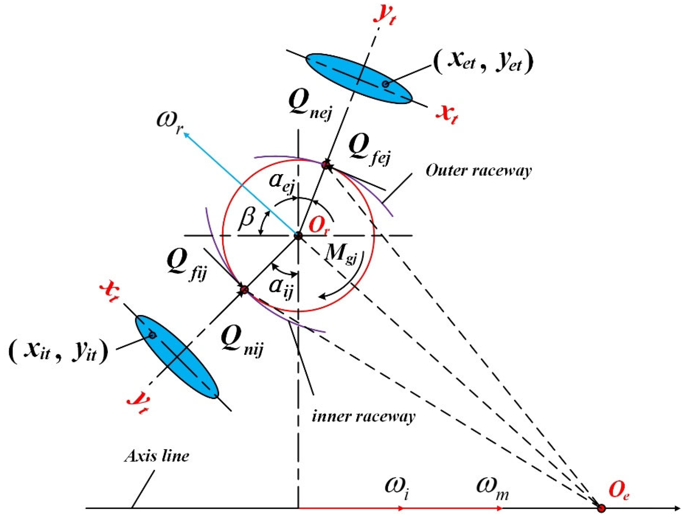
2.3. Interactive Force of Contact Elements

Contact and friction are common motion phenomena in ball bearings, originating from clearance. In the traditional dynamic model of ball bearings, Hertz’s contact theory is used for the contact-impact process of the ball, cage, and raceway. However, energy loss and damping hysteresis cannot be reflected by a purely elastic contact condition [36,37]. As is well known, dissipative energy is a real characteristic of movement in ball bearings. In an effort to clearly expose nonlinear vibration, the damping hysteresis characteristics and non-conformal features should be incorporated into the contact-force model. Based on the L-N contact-force model, the IMPACT function is developed, and the STEP term is employed to replace the hysteresis damping coefficient. The damping hysteresis is introduced into the contact-force model [28]. Compared with the traditional model of stiffness coefficient, the expression is revised by the structural parameters of raceway [27,31]. The expression of the contact-force model is depicted as:
Q n = K δ n + S T E P δ , 0 , 0 , d m a x , c m a x δ ˙ δ > 0 0 δ 0
S T E P δ , 0 , 0 , d m a x , c m a x = 0 δ < 0 c m a x δ d m a x 2 3 2 δ d m a x 0 < δ < d m a x c m a x δ d m a x
where δ is the penetration value of impact, and dmax and cmax are the boundary penetration and maximum damping coefficients, respectively.
Moreover, it is different from the revolute clearance joint, and the elliptical characteristics of the contact surface should be considered in the calculation of the general stiffness for angular contact ball bearings [8]. Then, the stiffness coefficient is written as
K k = π k e E r k ξ 3 ζ 3 1 2               k = i , e , c
where k e , ξ , and ζ are the ellipticity feature values, and E and r k denote the modulus elasticity and curvature sum, respectively.
Meanwhile, the friction force of contact elements should be listed. The modified Coulomb’s friction model is usually applied to represent the tangential force during the contact-impact process, which is denoted as
Q t = c f c d Q n υ t υ t
where c f and υ t are the friction coefficient and tangential velocity, respectively.
Then, the dynamic correction coefficient c d is defined as
c d = 0 i f υ t υ 0 υ t υ 0 υ 1 υ 0 i f υ 0 υ t υ 1 1 i f υ t υ 1
where ν 0 and ν 1 display the tangential velocity tolerance of the contact surface.

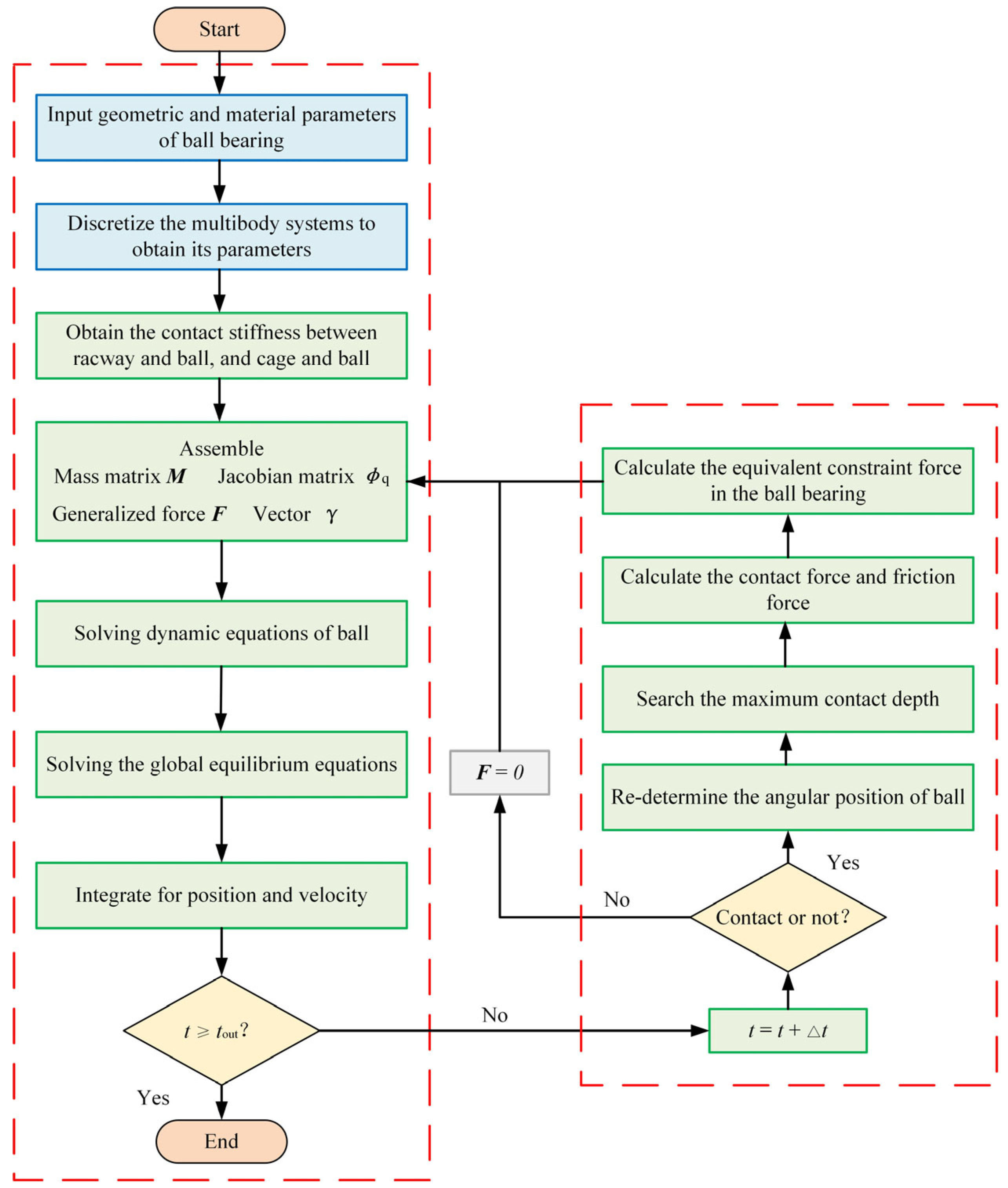
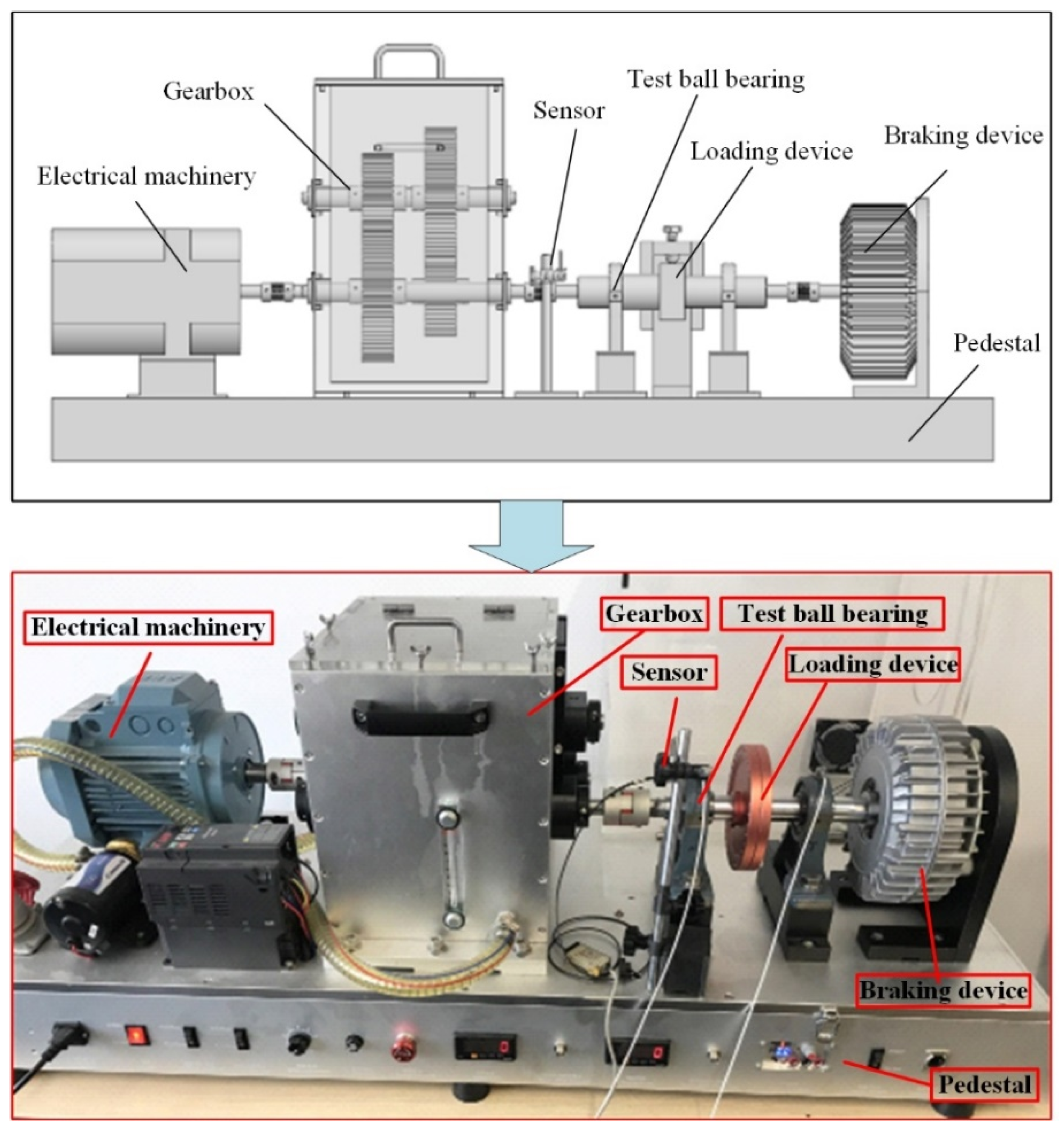
3. Solution and Experiment

The solution process of dynamic equations was an essential part of the numerical analysis, and the flowchart is shown in Figure 3. First, the multibody system of the angular contact ball bearing needed to be discretized with parameters such as geometrical relationships and material properties. Moreover, the contact stiffness of the ball, raceway and cage was calculated, and the results were used as the basic parameters of the dynamic simulation of the angular contact ball. To maintain better computational efficiency and accuracy, a multi-step integration approach was used in solving the nonlinear equations, and the Newton–Raphson was applied to satisfy the maximum iteration requirements for the calculation. Then, the dynamic and equilibrium equations were solved. When the iteration of the nonlinear equations converged, the kinematic characteristics and dynamic stability of the ball bearing were obtained.
According to the test object, the test platform consisted of the transmission part, loading device, and test element, as shown in Figure 4. The test ball bearing was located under the bearing seat, and the inner raceway was driven by the shaft. The gearbox was used to regulate the working conditions, and the external load was obtained by the loading device. Then, the motion state of the cage was recorded by the sensor. The parameters of the test ball bearing are listed in Table 1. According to the dynamic study, the clearance should be defined in the structural feature of a ball bearing, and the different working conditions are usually given in the experiment [2,4]. Based on the results in Refs. [30,35], the working conditions included rotation speed, external load and clearance size, which had crucial effects on dynamic behavior of ball bearing. In particular, the external load was closely related to the contact angle, and the external load was given in the axial and radial directions. Meanwhile, the design requirement of a ball bearing showed that the loading value and rotation speed should be satisfied by the dynamic response. In the simulation model, the outer raceway was fixed, and contact constraints were added between the ball, raceway, and cage. The driving speed was applied to the inner raceway, and the center of rotation was fixed to the ground. The comparison results of the test and simulation are plotted in Figure 5. It is clear that the velocity of the cage increases with the growth in the inner raceway. There is only a slight difference between the simulation and the experiment, which may have been caused by rotation speed fluctuations in the electrical machinery. The results illustrate that the proposed dynamic model could reveal the kinematic response of ball bearings under different conditions.

4. Results and Discussion

4.1. Dynamic Characteristics of the Ball Bearing Under a Uniform Motion State

The stable motion state is an important element of ball bearings during motion, and stability evaluation can be conducted using the dynamic characteristics, which include contact force, trajectory of mass center, and vortex motion characteristics. In this section, the inner raceway maintained a uniform motion state. Additionally, the deviation ratio of mass center velocity for a cage was used to expose the nonlinear motion response of the ball bearing. The expression can be written as
σ v = 1 q 1 i = 1 q v i v ¯ 2 v ¯
where v i is the instantaneous velocity of the mass center for the cage at any time, v ¯ denotes the average velocity of the mass center, and q represents the number of sampling points.
First, the influence of rotational speed on the vibration and impact of the ball bearing was considered. As the operating condition parameter, rotation speed changes the initial contact velocity and collision frequency. The effects of rotational speed on the vibro-impact feature of the ball bearing are given in this section. Figure 6 shows the contact force between the ball and the raceway, which clearly reveals the vibration of the contact-impact process. A higher working speed caused an obvious increase in the peak value of the contact-force trajectory. When the rotation speed was between 6000 and 8000 rpm, a larger contact force was found, mainly focusing on the loading region. The variation in the initial conditions changed the velocity and position of contact, and it was closely related to the value of the contact force based on the contact-force model. The variation in the gyroscopic moment also enhanced the vibro-impact phenomenon of contact elements, which was also a factor in the vibration of the angular contact ball bearing. Moreover, the contact frequency of ball and raceway retained a higher value, which was decided by the motion state of the ball. While the ball retains the free flight state, the value of the contact force is zero, which was the main reason that at some points the magnitude was intermittently zero. In addition, the active time of vibro-impact was very short, which made the contact force value fluctuate, and the phenomenon of intermittent zero was captured. In the steady state of ACBBs, the trajectory of the cage’s mass center is shown in Figure 7 and the deviation ratio of cage’s mass center velocity is represented in Figure 8. The results show that the motion trajectory of the cage gradually approached a regular circle at higher speeds, and the deviation ratio of the cage’s mass center velocity decreased at the same time. Although micro-vibration appeared in the motion of the cage, the stability of the vortex motion for the ball bearing improved. The main reason for the micro-vibration phenomenon could be concluded to be the high-frequency nonlinear contact of the ball. When the rotation speed was 4000 rpm, the ball exerted only slight traction forces on the cage, which caused an unstable vortex motion of the cage. The central zone of the motion trajectory was relatively chaotic, and the deviation ratio of the cage’s mass center velocity was larger. Then, the obvious vibro-impact phenomenon occurred in the motion, and the stability of the angular contact ball bearing was poor. The increase in rotation speed was the main reason for the growth in centrifugal force and friction effects, which satisfied the requirement of a traction force for vortex motion. This phenomenon of the ball provided a helpful guiding effect on the cage, and the deviation ratio of the cage’s mass center velocity was significantly reduced. Although the motion state of the cage was close to regular, the non-coincidence degree of the trajectory boundary was still clear. When the rotation speed exceeded 10,000 rpm, the trajectory boundary of the cage gradually became regular, following a circular pattern, and the ball bearing exhibited better motion stability. Furthermore, the working speed had a tenuous effect on the contact angle of the ball bearing, as plotted in Figure 9. Although the deviation was smaller, the contact angle changed at different position angles of the ball bearing. The results suggest that the loading value is closely related to the dynamic response of the ball, and the contact force in the unloading region is smaller than that in the loading zone. It is worth noting that the variation feature of the contact angle between ball and inner raceway differs from that between ball and outer raceway.
Second, the variation in external load was always considered in vibration and stability analyses of ball bearings. As the main parameter, external load was selected to determine the contact characteristics of the ball bearing. The contact force between ball and inner raceway was used to describe the contact characteristics during the motion, which is represented in Figure 10. The contact frequency and impact strength were sensitive to the loading region and squeezing force, which was caused by the center position. A larger external load generated a bigger deviation in the inner raceway center. Meanwhile, the greater penetration caused by the external load enhanced the production of contact force, and the motion of the ball became unstable. In the unloading region, the contact force showed a decreasing trend. It was generalized that the inner raceway gradually moved downward due to the external load, and the movement area of the ball expanded in the unloading region. It is worth noting that the elastic deformation of ball and raceway was produced by the vibro-impact. Additionally, the intermittent zero was mostly related to the vibro-impact phenomenon. Then, the contact frequency and penetration value were relatively small, which was the main reason for the decrease in contact force. The effects of the external load on the motion trajectory of the cage are displayed in Figure 11 and Figure 12. With the increase in external load, the trajectory of the cage’s mass center became disordered gradually, and the deviation ratio of the cage’s mass center velocity increased obviously, indicating a decrease in the stability of the ball bearing. When the external load exceeded 5000 N, the motion trajectory remained relatively regular, and the coincidence of the trajectory boundary was high. However, vibration appeared in the trajectory boundary of the cage as the external load grew. The reason for this can be explained by the decrease in the friction force between the ball and cage, which became lower than the demand for vortex motion. Under the condition F = 12,500 N, chaotic characteristics of the cage appeared in the motion trajectory. The geometric relationship between the ball and cage became mismatched and unstable, leading to an increase in the deviation ratio of the cage’s mass center. Moreover, the damping effects of the contact-impact phenomenon were revealed in the contact force and trajectory of the cage’s mass center. With high-frequency contact, the value of the contact force changed, and the recurrent fluctuations were caused by the damping force. A similar phenomenon was also found in the motion trajectory of the cage’s mass center, and the change of position was close related to the contact deformation, which would produce the energy loss. Furthermore, the influence of external load on the contact angle is shown in Figure 13. As the external load varied, the contact angle showed different appearances at different position angles. The contact angle decreased slowly in the unloading region and increased in the loading zone. The results also reflect worsened kinematic features and stability of the ball bearing with clearance under a larger external load. Meanwhile, the contact angle could determine the transmission direction of loading and applied forces, which are associated with the bearing capacity. A bigger contact angle would provide a higher supporting force in the axial direction. In traditional bearing modeling approaches, the Hertzian contact theory was widely adopted to describe the nonlinear elastic deformation at the contact interface, which inherently neglected damping effects. This simplification remained valid under low-speed conditions or light loading scenarios where the relative radial motion between rolling elements and races was minimal. However, at high rotational speeds or under heavy loads, significant tangential sliding velocities occurred at the contact zones due to centrifugal forces, gyroscopic moments, and dynamic load redistribution. Neglecting damping in such scenarios led to an overestimation of high-frequency vibrations in the simulated system. This was because the undamped model cannot dissipate the energy generated by rapid transient interactions between components, resulting in unphysical oscillations that deviate from real-world behavior. By incorporating a velocity-dependent viscous damping termed into the contact model (e.g., through a linear or nonlinear damping coefficient), the energy dissipation mechanism was captured. This phenomenon allowed the model to attenuate high-frequency vibrational modes while preserving low-frequency dynamic characteristics, thereby aligning simulation results more closely with actual situations. The results demonstrate that damping played a critical role in suppressing resonance amplification and improving the accuracy of vibration spectra predictions, particularly in high-speed operational regimes.
In addition, the clearance size was also the main factor in the motion stability of the ball bearing. Clearance was the key source of the contact impact, and the distribution region of the contact characteristics also changed, as shown in Figure 14. The dynamic failure of the ball bearing usually originated from chaotic motion. Because the variation in clearance size affected the initial contact velocity, the contact force and impact deformation also changed at the same time. The growth in clearance size caused a decline in the contact velocity at the initial contact point, and the interaction between the ball and the raceway weakened. When the ball was located in the unloading region, the contact force decreased significantly, reaching zero in the special zone. The results show that the inner raceway moved downward due to the clearance and external load, and the ball had a larger space for movement in the unloading region. Additionally, the time of the free flight state for the ball in the unloading region was increased. Figure 15 and Figure 16 show that a larger clearance value disturbed the movement trajectory of the cage, and the stability of vortex motion also changed. When the clearance size was 0.02 mm, the geometric relationship between the ball and cage was well matched, and the cage maintained a steady vortex motion due to greater traction force. When the clearance size was 0.08 mm, the guiding effect of the ball on the cage was weakened, which could not promote a stable vortex motion of the cage, and chaotic characteristics appeared. As the clearance size increased, the vortex motion of the cage completely disappeared, and the boundary of motion became concentrated. A smaller traction force was not enough to maintain the vortex motion of the cage, and the larger deviation ratio of the cage’s mass center led to a weakening of motion stability. Meanwhile, the sliding phenomenon could appear under this condition, and the nonlinear vibration of motion was promoted. The variation rule of the contact angle of the ball bearing is shown in Figure 17. Although a deviation in the contact angle was observed, the change path was similar, and the reduction speed was relatively gentle. This feature was explained by the fact that a larger clearance size could break the constraint effect of the raceway on the ball, which caused a decrease in contact force and contact angle. The contact angle of the outer raceway had a similar motion trajectory, and the contact angle reached the maximum value in the loading region.

4.2. Dynamic Characteristics of the Ball Bearing Under Various Motion States

In fact, the motion of the inner raceway was not always uniform, and the fluctuation in rotation speed was inevitable due to the effects of operating conditions. The unstable motion state caused a decline in the stability of the angular contact ball bearing, and the clearance size in the ball bearing components changed with the variation in working conditions. Therefore, it was necessary to investigate the vibro-impact characteristics of the ball bearing under various motion states, which included different types of waves and acceleration conditions.
As shown in Figure 18, three types of waves were chosen to be introduced into the driving speed (rectangle, triangle, and sine). The external load was 5000 N, and the driving speed was 10,000 rpm. The period and amplitude of the three types of waves were conducted under the same conditions. Figure 19 shows the effect of different rotation speeds on the motion state of the cage. The triangle and sine waves had little effect on the motion trajectory of the cage, and the movement followed a relatively regular path. However, with the effect of the rectangle wave, bifurcation characteristics were found in the motion trajectory, and the degree of coincidence was lower than that of the other waves. The negative effects on dynamic behavior were closely related to the variation in clearance size, which played an important role in the contact force during the motion. Due to the obvious mutation, the rectangle wave enhanced the contact-impact process and acting force, which caused a decline in motion stability for the ball bearing. Although the mutation feature also existed in the triangle and sine waves, the velocity gradient was smaller, and the change process was relatively slower, which helped to restrain the appearance of the contact-impact phenomenon. The motion state of the ball had significant nonlinear characteristics, and the fluctuation phenomenon appeared in the trajectory of the cage’s mass center. Figure 20 illustrates the relationship between various types of rotation speed and contact force. According to the results, fluctuation was observed in the contact-force value, which made the nonlinear response more obvious. Meanwhile, the motion of the elements in the ball bearing was in an unstable state. Relatively speaking, the contact characteristics are more sensitive to the change in the rectangle wave, while the variation effects of the sine wave were the lowest. In Figure 21, the nonlinear vibration behavior in the motion trajectory is shown in greater detail. The features of the three types of waves led to the appearance of periods in the axial displacement of the inner raceway, but the rectangle wave produced clear vibration. Furthermore, the variation in rotation speed affected the motion stability of the cage, and nonlinear fluctuations appeared in the sliding ratio of the cage, which was an important factor in the design of the ball bearings.
In addition, the acceleration of the inner raceway had serious effects on the dynamic behavior of the angular contact ball bearing. The contact and vibration damaged the ball bearing components during the acceleration process, and the continuous variation in clearance size produced a complex vibro-impact phenomenon in the motion trajectory. The acceleration value was also a significant factor in determining the nonlinear vibro-impact characteristics of the ball bearing. The acceleration value was defined as constant, and the driving speed followed a linear growth. The transient motion trajectory of the cage’s mass center is shown in Figure 22. The results explain that the movement state of the cage retained high-frequency vibration characteristics during the acceleration. The increase in acceleration enlarged the motion range of the cage, and the kinematic trajectory became erratic. The results indicate that a higher rotation speed of the inner raceway could improve the activity level and promote chaotic motion. The larger contact force and higher contact frequency produced a more active motion for the cage (in Figure 23), which was the main factor contributing to unstable motion. It is clearly seen that there are more points of magnitude with intermittent zero values. Moreover, the transient axial position of the inner raceway moved faster within the same time as the acceleration increased (Figure 24). Based on the growth in acceleration, there were larger action forces and higher response frequencies, and the obvious contact characteristics led to variations in the inner raceway position. A similar change feature was observed in the transient rotation speed of the cage, as displayed in Figure 25. The rotation speed of the cage with different accelerations showed various vibration amplitudes. The conclusion drawn was that smaller acceleration values are associated with weaker dynamic effects. When the acceleration remains at a lower value, the kinematic characteristics of ACBB cannot retain the smooth variation. With the increase in free flight motion time for ball and cage, the impact strength was improved, especially in the process of constraint condition conversion. The kinematic features and dynamic stability of the ball bearing components were highly unstable due to the stronger nonlinearity of the contact process. Consequently, obvious vibrations and transient impacts were observed in the dynamic response of the ball bearing.

5. Conclusions

Considering clearance effects, an analysis method for nonlinear vibro-impact characteristics in angular contact ball bearings was presented, which was employed to predict the dynamic response and analyze the parameter sensitivity. The relative motion state of contact elements and micro-deformation were determined by the motion state, where the continuous contact-force model and modified friction model were applied to represent the contact features of ball bearing elements. The dissipative term of contact impact was introduced into the motion equations, and the kinematic constraints of components were determined by the reaction forces. Moreover, the velocity vector of components was used to describe the uncertain parameters of kinematics and dynamics. Based on the Newton–Raphson method, the recommended solution process and dynamic experiment for angular contact ball bearings demonstrate the effectiveness of the proposed method. The conclusions can be summarized as follows:
(1)
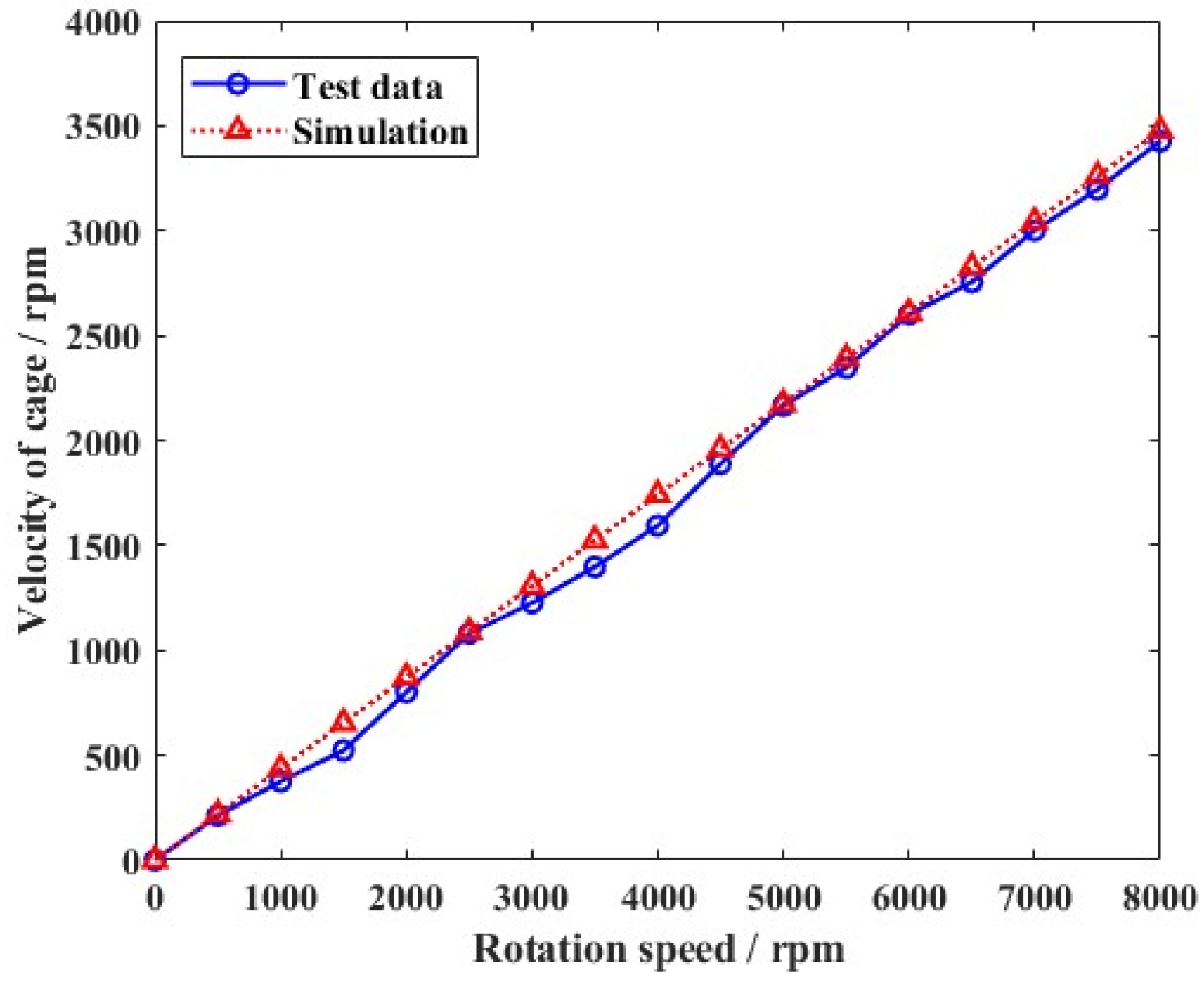
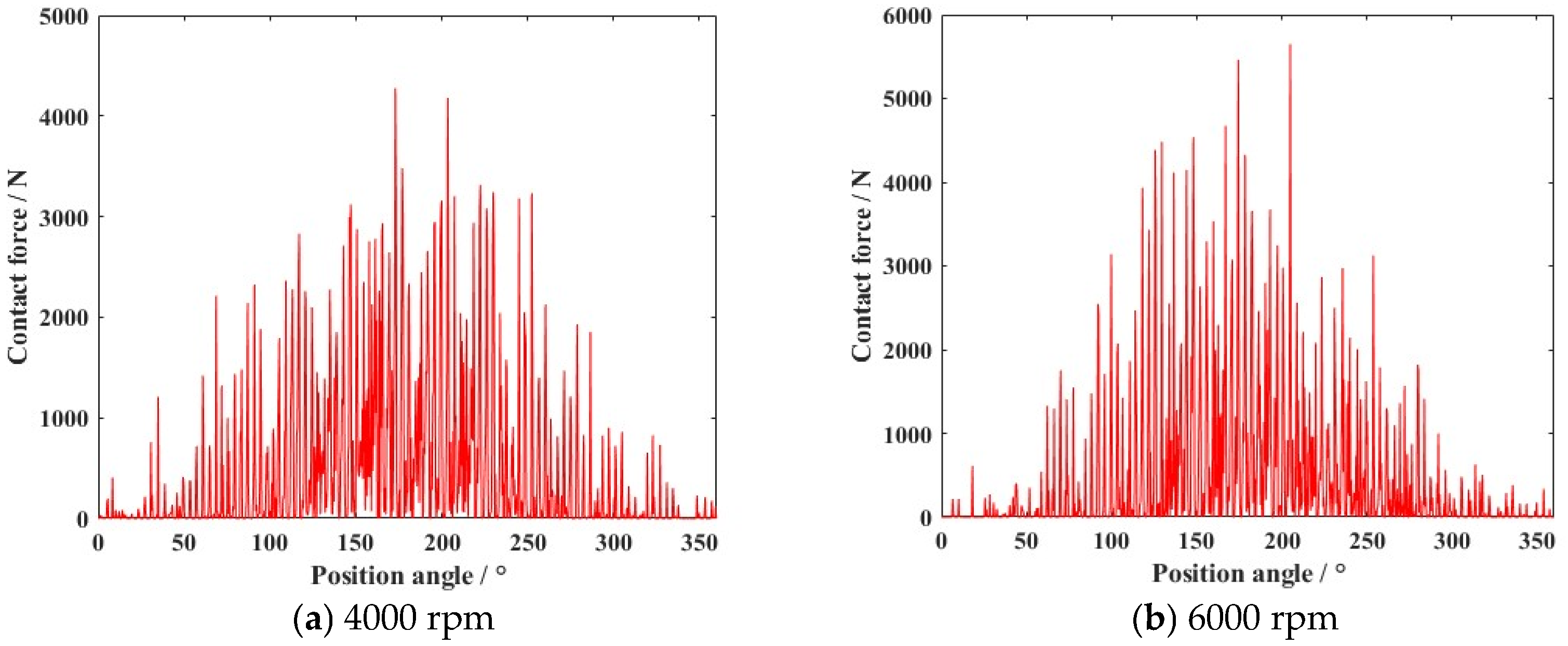
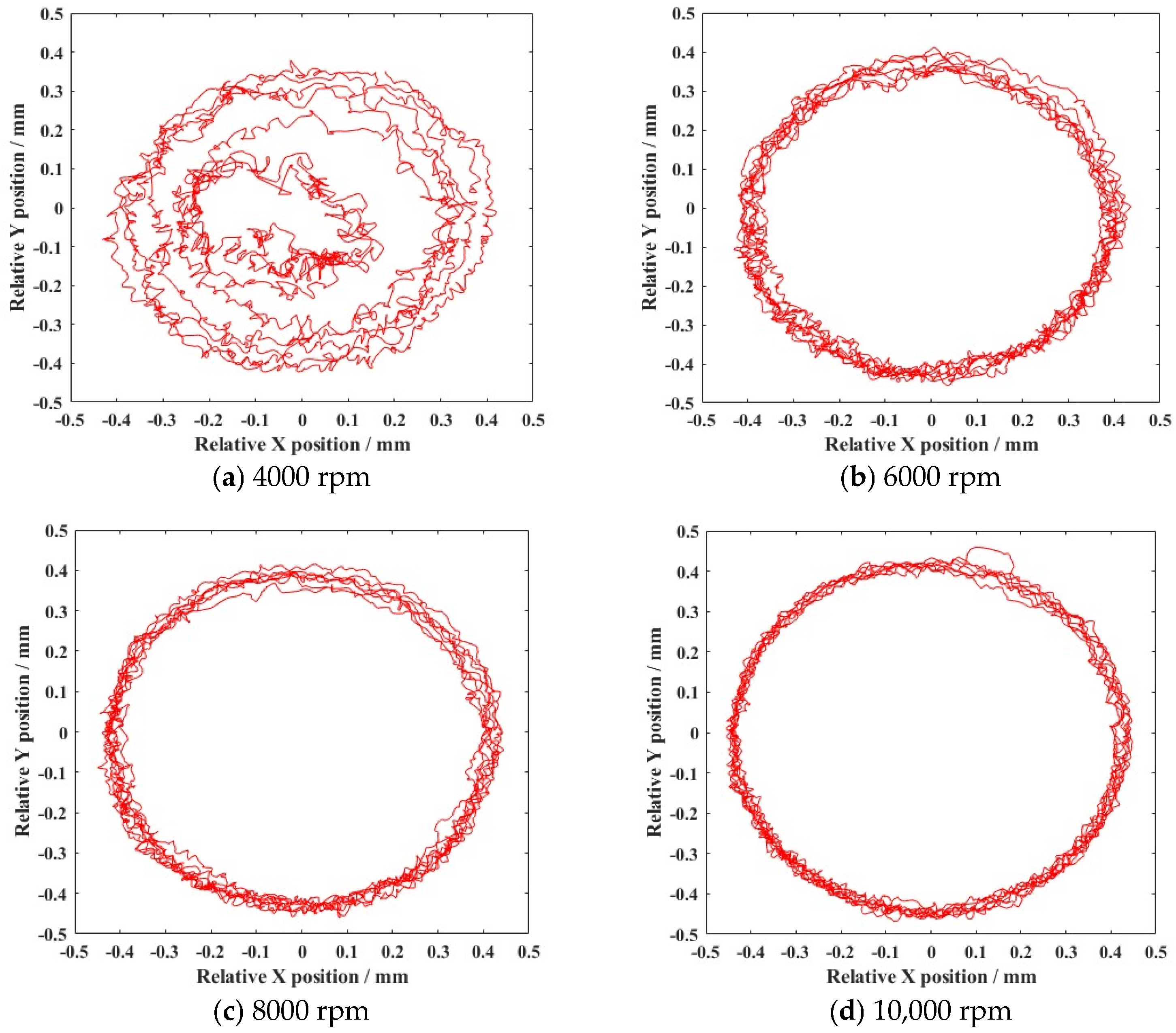
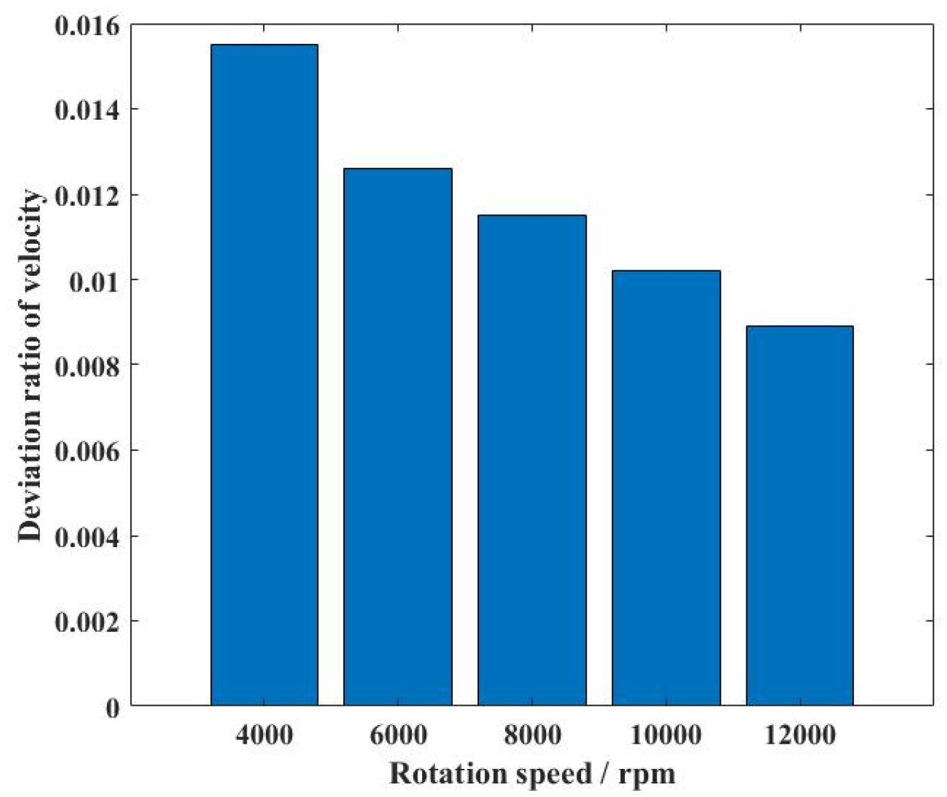
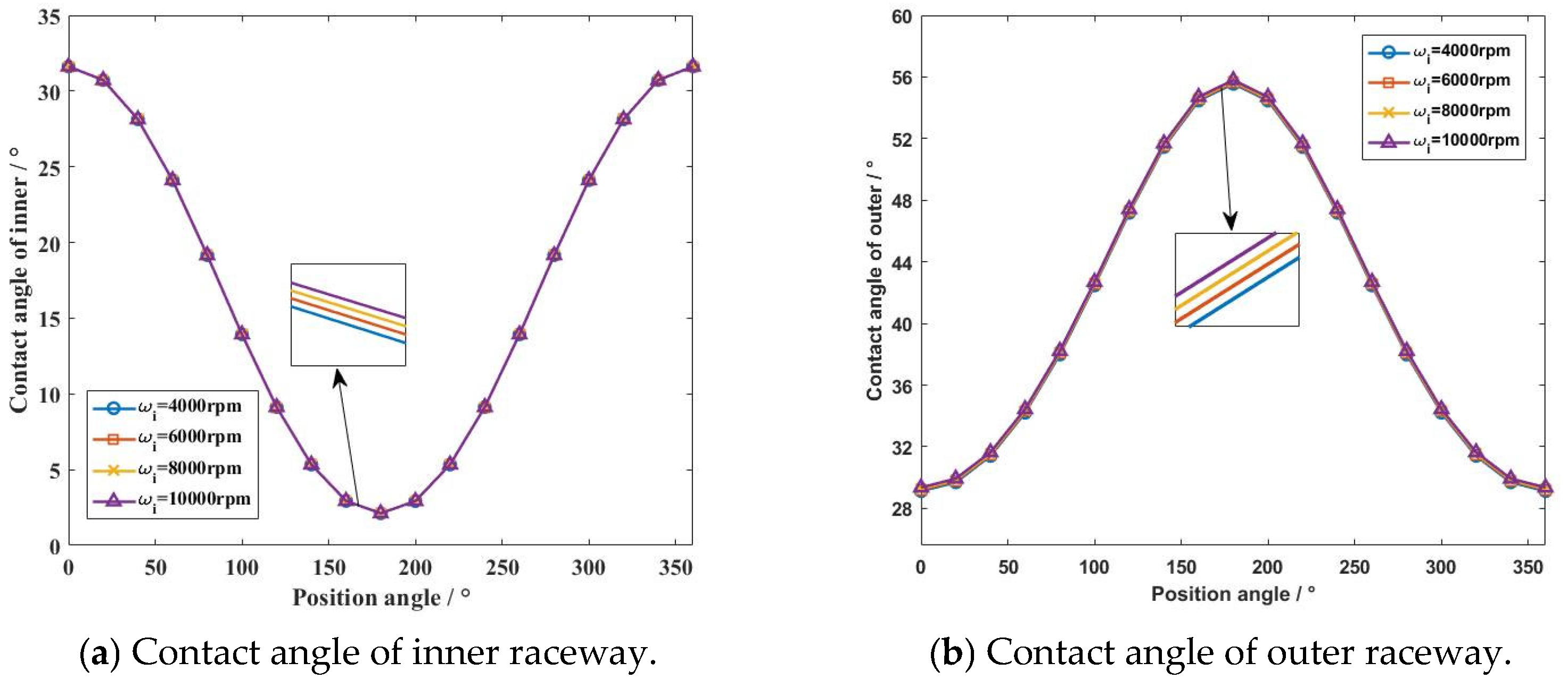
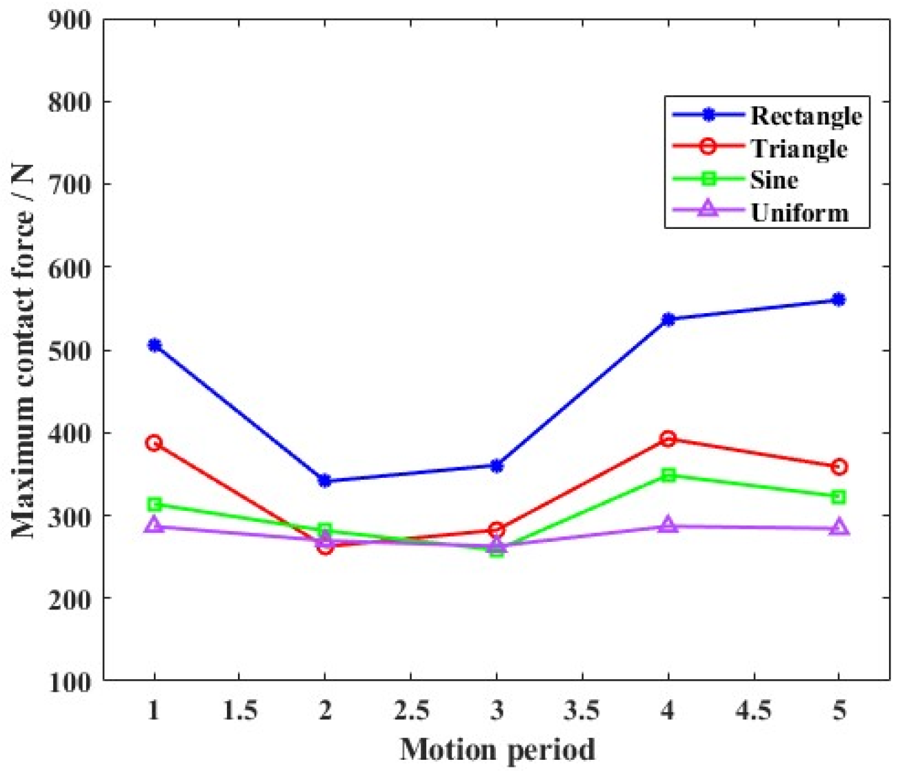
According to the simulation results, clearance caused high-frequency collisions of the ball bearing elements. In the uniform motion state, the contact force increased with the growth in rotation speed, and the deviation in vortex motion led to worsened stability of the cage.
(2)
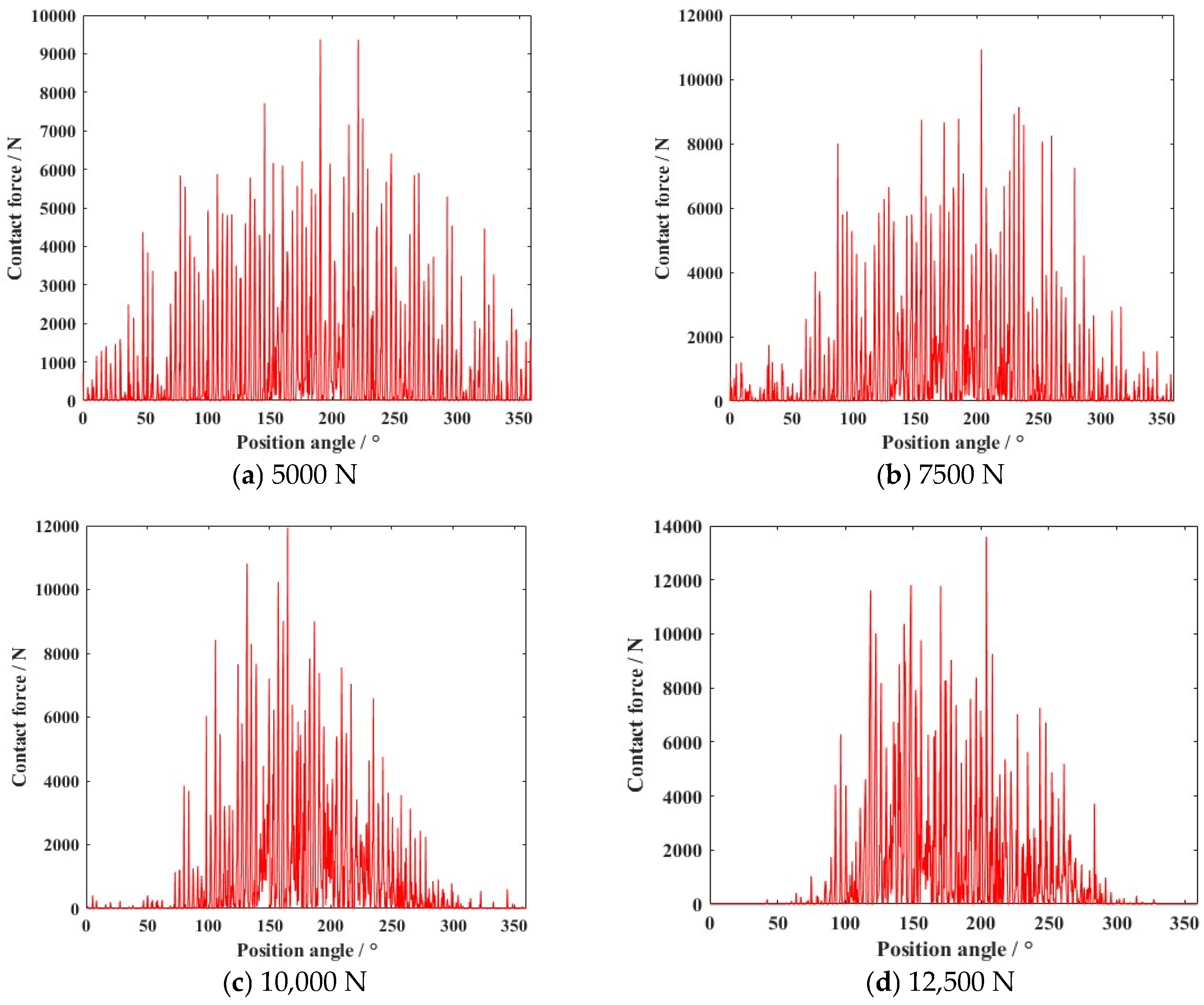
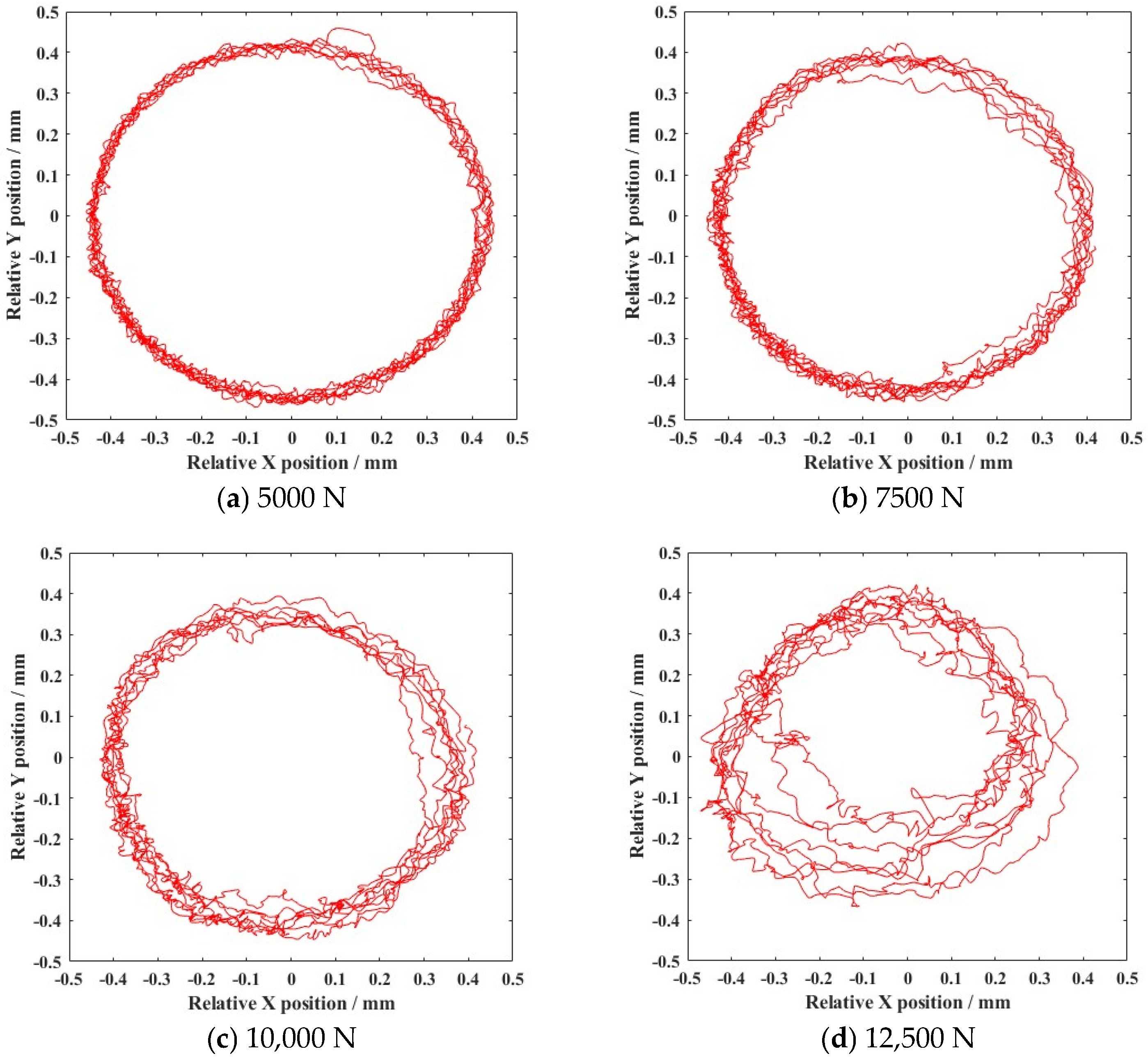
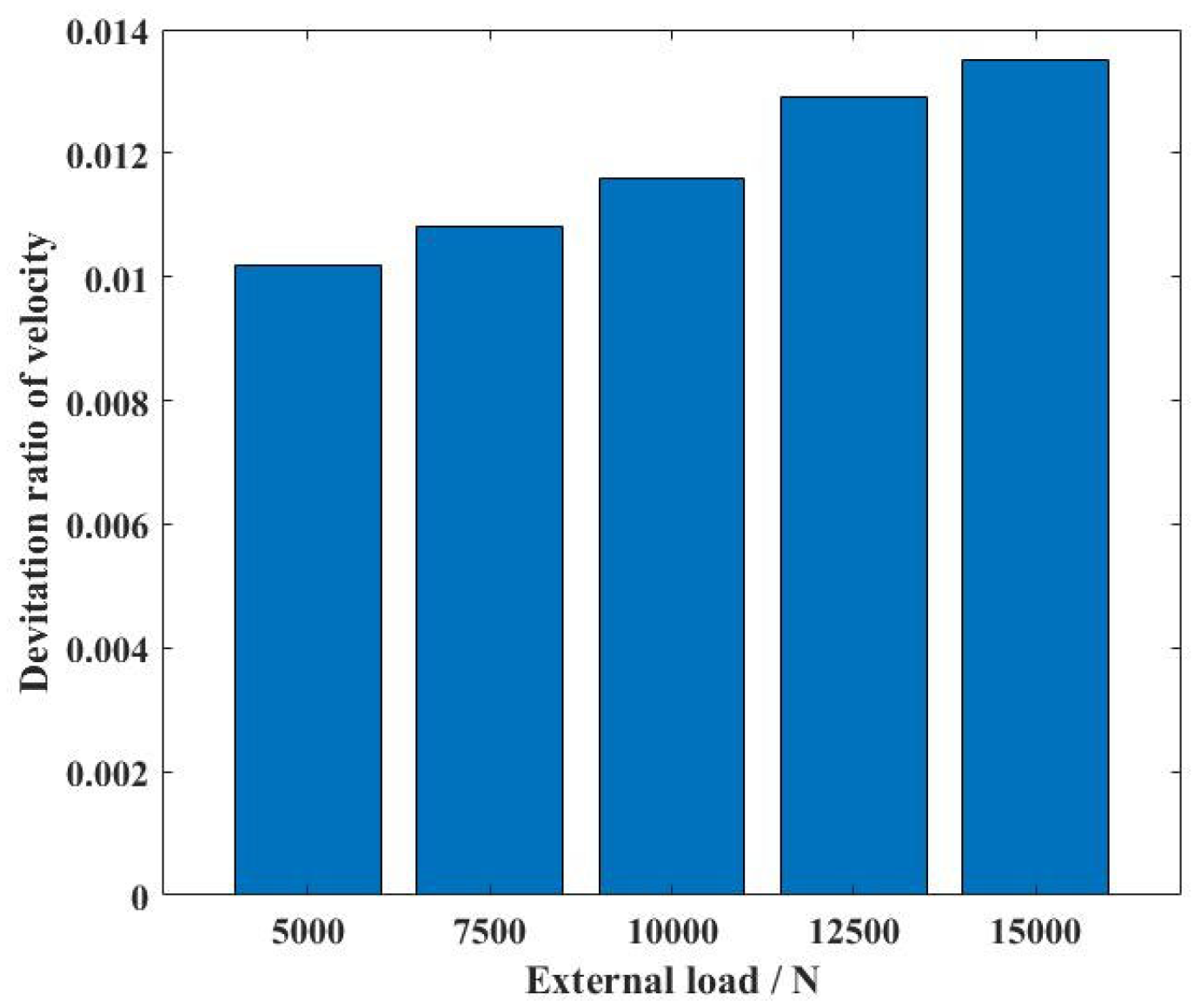
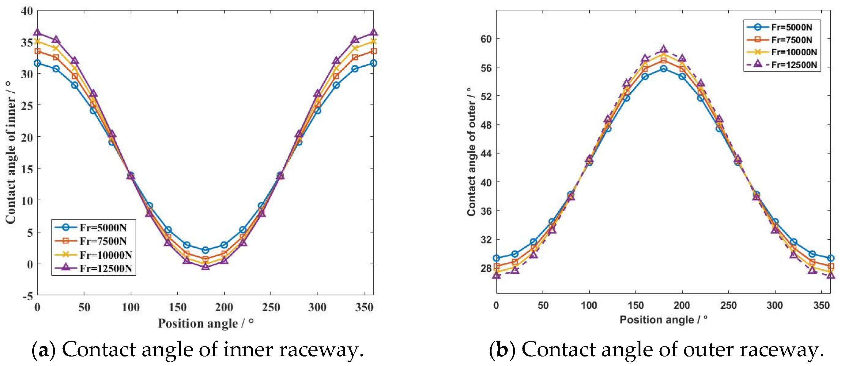
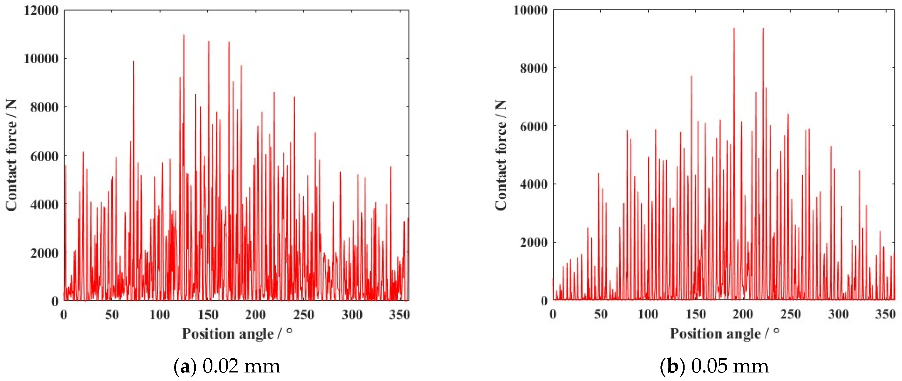
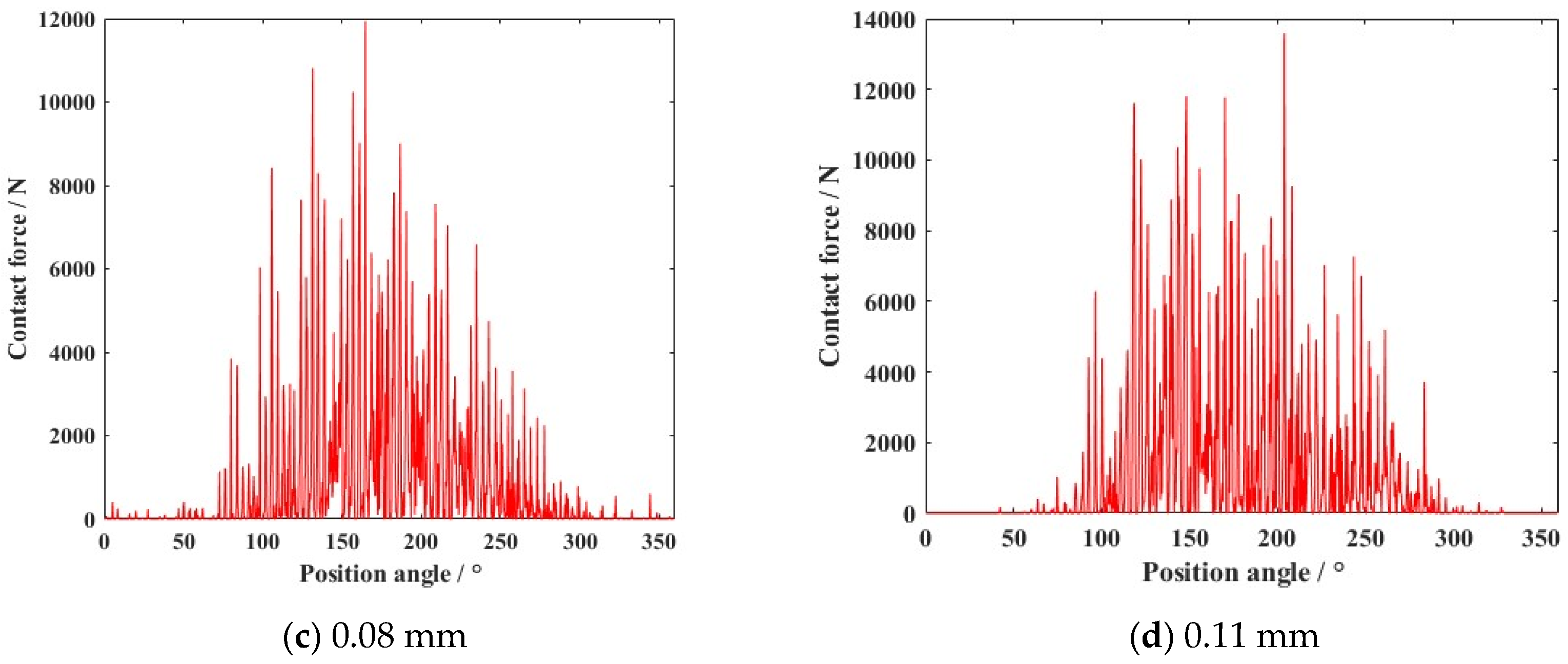
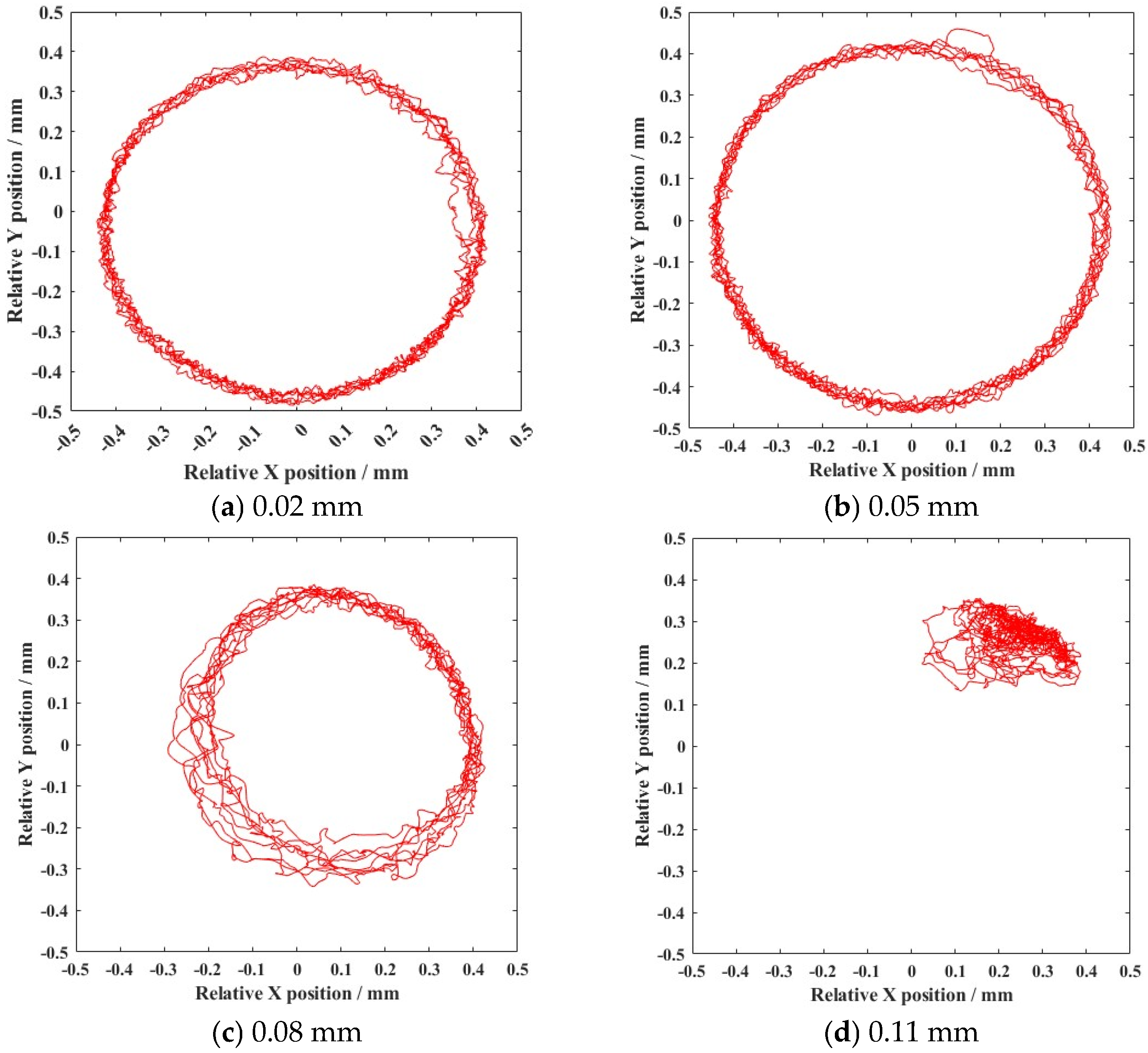
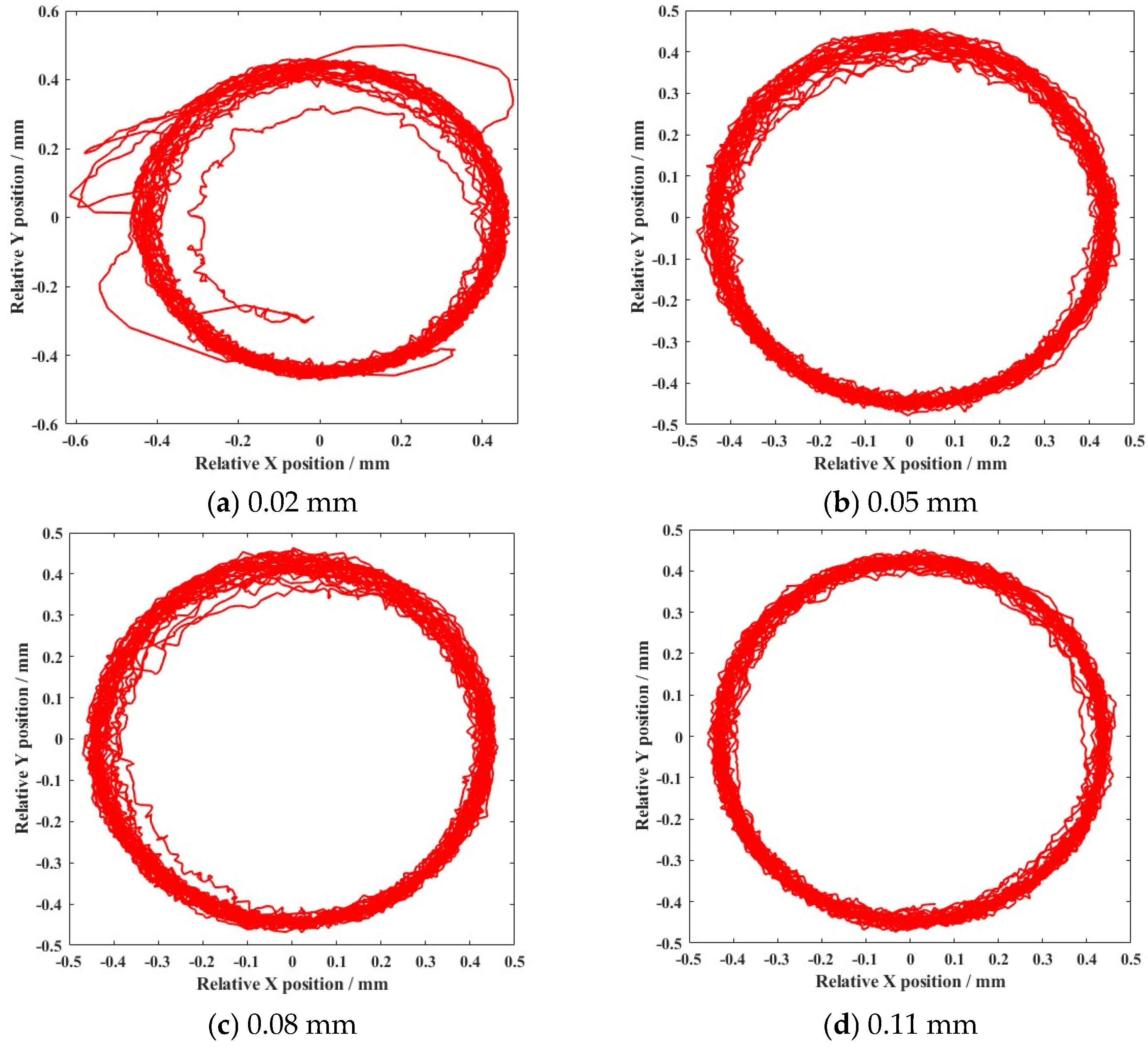
The variation in external load and clearance size were the main factors contributing to the appearance of nonlinear dynamic responses. With the growth in external load increase (from 5000 N to 12,500 N), the deviation ratio of the cage’s mass center velocity increased to 24.44%. The change of clearance size (from 0.02 mm to 0.14 mm) improved the deviation ratio of cage’s mass center velocity (33.11%).
(3)
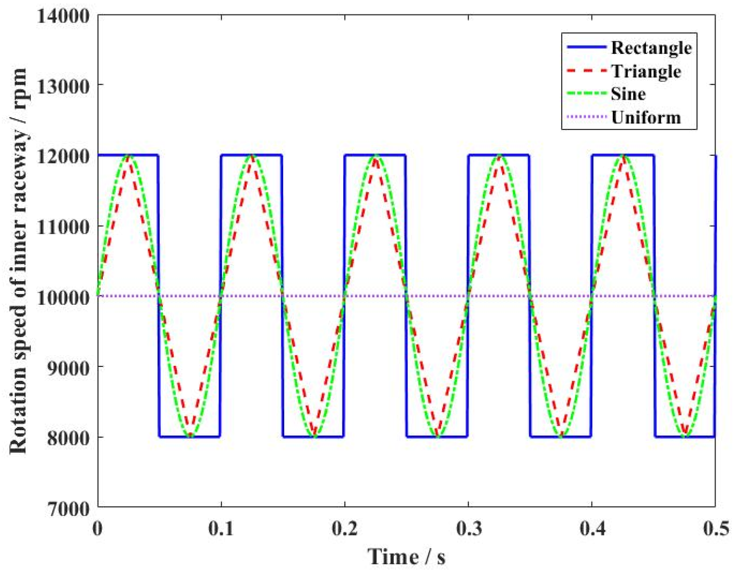
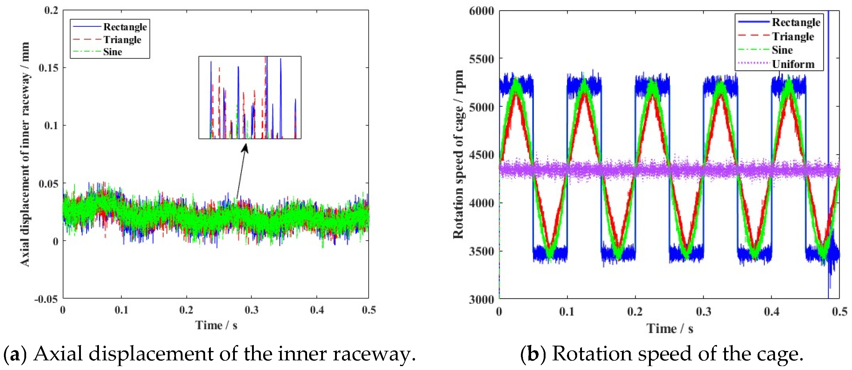
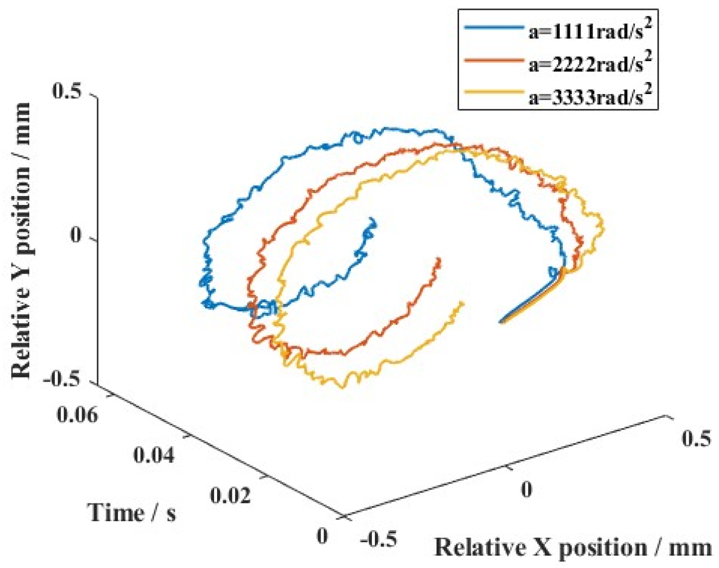
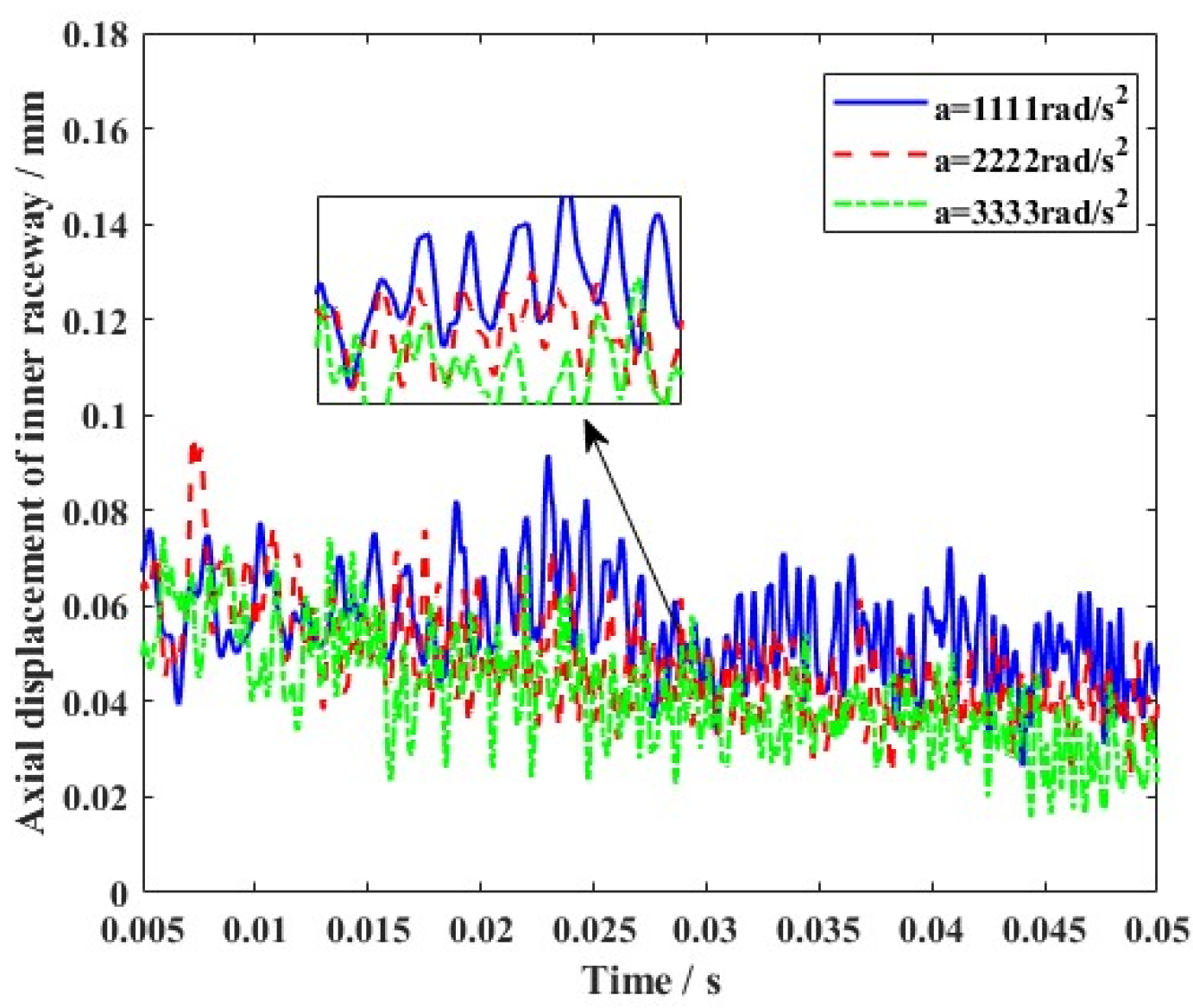
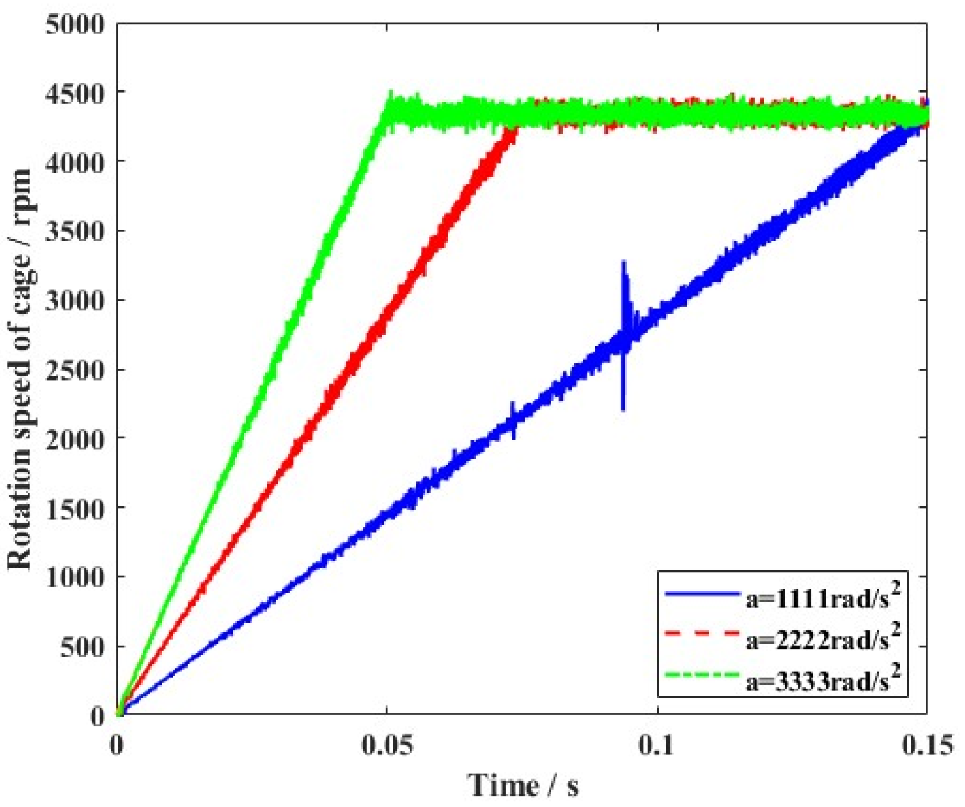
Furthermore, variable clearance in ball bearing components was produced in various motion states. Although vibration was always observed during motion, the varying gradient was sensitive to the outline of the rotation speed wave. The slow change in operating conditions helped restrain the nonlinear vibration characteristics, which was more suitable for the stability of angular contact ball bearings.

Author Contributions

Methodology, Software Y.Z.; Validation, X.P.; Writing—review & editing, Y.C. All authors have read and agreed to the published version of the manuscript.

Funding

This research received no external funding.

Data Availability Statement

The original contributions presented in this study are included in the article. Further inquiries can be directed to the corresponding author.

Conflicts of Interest

The authors declare that they have no conflicts of interest with the contents of this article.

References

  1. Deng, S.; Gu, J.; Cui, Y. Dynamic analysis of a tapered roller bearing. Ind. Lubr. Tribol. 2017, 70, 191–200. [Google Scholar] [CrossRef]
  2. Xu, L.; Li, Y. Modeling of a deep-groove ball bearing with waviness defects in planar multibody system. Multibody Sys. Dyn. 2015, 33, 229–258. [Google Scholar] [CrossRef]
  3. Bover, C.; Zamponi, I. An approach for predicting the internal behavior of ball bearings under high moment load. Mech. Mach. Theory 2016, 101, 1–22. [Google Scholar]
  4. Chen, Y.; Wu, X.; Wang, X. Clearance-induced contact trajectory uncertainty of angular contact ball bearing under coupling operating condition. Meccanica 2023, 58, 43–66. [Google Scholar] [CrossRef]
  5. Liu, J.; Shao, Y. Dynamic modeling for rigid rotor bearing systems with a localized defect considering additional deformations at the sharp edegs. J. Sound Vib. 2017, 398, 84–102. [Google Scholar] [CrossRef]
  6. Xi, H.; Wang, H.; Han, W. Contact trajectory of angular contact ball bearings under dynamic operating condition. Tribol. Int. 2016, 104, 247–262. [Google Scholar] [CrossRef]
  7. Ma, S.; Li, W.; Yan, K.; Li, Y.; Zhu, Y.; Hong, J. A study on the dynamic contact feature of four-contact-point ball bearing. Mech. Syst. Signal Pract. 2022, 174, 109111. [Google Scholar] [CrossRef]
  8. Chen, X.; Wang, T.; Jiang, S. Study on dynamic behavior of planar multibody system with multiple lubrication clearance joints. Eur. J. Mech. A Solid. 2022, 91, 104404. [Google Scholar] [CrossRef]
  9. Yao, T.; Xian, L.; Wang, L.; Liu, X. Multibody contact dynamics on mechanisms with deep groove ball bearing joints. J. Mech. Sci. Technol. 2017, 31, 4119–4135. [Google Scholar] [CrossRef]
  10. Yan, K.; Wang, N.; Zhai, Q.; Zhu, Y.; Zhang, J.; Niu, Q. Theoretical and experimental investigation on the thermal characteristics of double-row tapered roller bearings of high speed locomotive. Int. J. Heat Mass Transf. 2015, 84, 1119–1130. [Google Scholar] [CrossRef]
  11. Han, Q.; Li, X.; Chu, F. Skidding behavior of cylindrical roller bearings under time-variable load conditions. Int. J. Mech. Sci. 2018, 135, 203–214. [Google Scholar] [CrossRef]
  12. Li, H.; Li, H.; Liu, Y.; Liu, H. Dynamic characteristics of ball bearing with flexible cage lintel and wear. Eng. Fail. Anal. 2020, 117, 104956. [Google Scholar] [CrossRef]
  13. Liu, Y.; Liu, H. A coupled model of angular-contact ball bearing-elastic rotor system and its dynamic characteristics under asymmetric support. J. Vib. Eng. Technol. 2021, 9, 1175–1192. [Google Scholar] [CrossRef]
  14. Zhang, D.; Wu, D.; Han, Q.; Wang, H. Dynamic force transmissibility of flywheel rotor systems supported by angular contact ball bearings considering clearance fit. Eur. J. Mech. A Solids 2022, 92, 104457. [Google Scholar] [CrossRef]
  15. Liu, P.; Wang, L.Q.; Ma, F.; Zheng, D.; Wu, J.; Li, Z. Influence of assembly clearance on vibration characteristics of angular contact ball bearings in the thermal environment. Tribol. Int. 2023, 181, 108317. [Google Scholar] [CrossRef]
  16. Prashant, H.J.; Santosh, P.B. Mathematical modeling, simulation and analysis of non-linear vibrations of a ball bearing due to radial clearance and number of balls. Mater. Today Proc. 2023, 72, 927–936. [Google Scholar]
  17. Gao, S.; Wang, L.; Zhang, Y. Modeling and dynamic characteristics analysis of high speed angular contact ball bearing with variable clearance. Tribol. Int. 2023, 182, 108330. [Google Scholar] [CrossRef]
  18. Xiao, S.; Liu, S.; Wang, H.; Lin, Y.; Song, M.; Zhang, H. Nonlinear dynamics of coupling rub-impact of double translational joints with subsidence considering the flexibility of piston rod. Nonlinear Dyn. 2020, 100, 1203–1229. [Google Scholar] [CrossRef]
  19. Shishvan, S.S.; Zarnagh, M.H.D.; Deshpande, V.S. Energy dissipation and effective properties of a nominally elastic composite material. Eur. J. Mech. A Solids 2022, 92, 104452. [Google Scholar] [CrossRef]
  20. Saeed, E.; Esmaeil, S.; Mohsen, M. Application of the method of multiple scales for nonlinear vibration analysis of mechanical systems with dry and lubricated clearance joints. J. Theor. Appl. Vib. Acoust. 2017, 3, 41–60. [Google Scholar]
  21. Zheng, E.; Wang, T.; Guo, J. Dynamic modeling and error analysis of planar flexible multilink mechanism with clearance and spindle-bearing structure. Mech. Mach. Theory 2019, 131, 234–260. [Google Scholar] [CrossRef]
  22. Mohamed, G.; Yildirim, H. A new contact force model for low coefficient of restitution impact. J. Appl. Mech. 2012, 79, 064506. [Google Scholar]
  23. Wang, X.; Liu, G.; Ma, S. Dynamic analysis of planar mechanical systems with clearance joints using a new nonlinear contact force model. J. Mech. Sci. Technol. 2016, 30, 1537–1545. [Google Scholar] [CrossRef]
  24. Qi, Z.; Wang, G.; Zhang, Z. Contact analysis of deep groove ball bearings in multibody systems. Multibody Syst. Dyn. 2015, 33, 115–141. [Google Scholar] [CrossRef]
  25. Hu, S.; Guo, X. A dissipative contact force model for impact analysis in multibody dynamics. Mulibody Syst. Dyn. 2015, 35, 131–151. [Google Scholar] [CrossRef]
  26. Tian, Q.; Lou, J.; Mikkola, A. A new elastohydrodynamic lubricated spherical joint model for rigi-flexible multibody dynamics. Mech. Mach. Theory 2017, 107, 210–228. [Google Scholar] [CrossRef]
  27. Tian, Q.; Flores, P.; Lankarani, H.M. A comprehensive survey of the analytical, numerical and experimental methodologies for dynamics of multibody mechanical systems with clearance or imperfect joints. Mech. Mach. Theory 2018, 122, 1–57. [Google Scholar] [CrossRef]
  28. Bai, Z.; Sun, Y. A study on dynamics of planar multibody mechanical systems with multiple revolute clearance joints. Eur. J. Mech. A Solids 2016, 60, 95–111. [Google Scholar] [CrossRef]
  29. Bai, Z.; Jiang, X.; Li, J.; Zhao, J.; Zhao, Y. Dynamic analysis of mechanical system considering radial and axial clearances in 3D revolute clearance joints. J. Vib. Control 2020, 27, 1893–1909. [Google Scholar] [CrossRef]
  30. Gao, S.; Chatterton, S.; Naldi, L.; Pennacchi, P. Ball bearing skidding and over-skidding in large-scale angular contact ball bearings: Nonlinear dynamic model with thermal effects and experimental results. Mech. Syst. Signal Process. 2021, 147, 107120. [Google Scholar] [CrossRef]
  31. Li, Y.; Wang, Z.; Wang, C.; Huang, W. Planar rigid-flexible coupling spacecraft modeling and control considering solar array deployment and joint clearance. Acta Astronaut. 2018, 142, 138–151. [Google Scholar] [CrossRef]
  32. Li, Y.; Yang, Y.; Li, M.; Liu, Y.; Huang, Y. Dynamics analysis and wear prediction of rigid-flexible coupling deployable solar array system with clearance joints considering solid lubrication. Mech. Syst. Signal Process. 2022, 162, 108059. [Google Scholar] [CrossRef]
  33. Zhang, J.; Fang, B.; Yan, K.; Hong, J. A novel model for high-speed angular contact ball bearing by considering variable contact angles. J. Mech. Sci. Technol. 2020, 34, 809–816. [Google Scholar] [CrossRef]
  34. Bai, Z.; Chen, J.; Sun, Y. Effects of contact force model on dynamics characteristics of mechanical system with revolute clearance joints. IJST Trans. Mech. Eng. 2014, 38, 375–388. [Google Scholar]
  35. Tu, W.; He, H.; Luo, Y. Dynamic skidding behavior of rolling elements under bearing steady working conditions. J. Vib. Shock 2019, 38, 94–99. [Google Scholar]
  36. Liu, J.; Shao, Y. An improved analytical model for a lubricated roller bearing including a localized defect with different edge shapes. J. Vib. Control 2018, 24, 3894–3907. [Google Scholar] [CrossRef]
  37. Yu, C.; Zhu, Y.; Shi, F. Accurate prediction method of initial value of high-speed ball bearing model and gyroscopic torque. J. Sound Vib. 2020, 481, 115419. [Google Scholar] [CrossRef]
Figure 1. Geometric relationship of a ball bearing. (a) Structural feature; (b) Geometric position; (c) Geometric parameters.
Lubricants 13 00216 g001
Figure 2. Applied force distribution in a ball bearing.
Lubricants 13 00216 g002
Figure 3. Calculation flowchart of the simulation.
Lubricants 13 00216 g003
Figure 4. Experimental mechanism of a ball bearing.
Lubricants 13 00216 g004
Figure 5. Comparison of the simulation and the experiment.
Lubricants 13 00216 g005
Figure 6. Contact force (ball and inner raceway) under different rotation speeds.
Lubricants 13 00216 g006aLubricants 13 00216 g006b
Figure 7. Trajectory of mass center for cage under different rotation speeds.
Lubricants 13 00216 g007
Figure 8. Deviation ratio of cage’s mass center velocity under different rotation speeds.
Lubricants 13 00216 g008
Figure 9. Variation in the contact angle under different rotation speeds.
Lubricants 13 00216 g009
Figure 10. Contact force (ball and inner raceway) under different external loads.
Lubricants 13 00216 g010
Figure 11. Trajectory of cage’s mass center under different external loads.
Lubricants 13 00216 g011
Figure 12. Deviation ratio of cage’s mass center velocity under different external loads.
Lubricants 13 00216 g012
Figure 13. Variation in the contact angle under different external loads.
Lubricants 13 00216 g013
Figure 14. Contact force (ball and inner raceway) under different clearance sizes.
Lubricants 13 00216 g014aLubricants 13 00216 g014b
Figure 15. Trajectory of cage’s mass center under different clearance sizes (uniform motion state).
Lubricants 13 00216 g015
Figure 16. Deviation ratio of cage’s mass center velocity under different clearance sizes.
Lubricants 13 00216 g016
Figure 17. Variation in the contact angle under different clearance sizes.
Lubricants 13 00216 g017
Figure 18. Different types of waves in rotation speed.
Lubricants 13 00216 g018
Figure 19. Trajectory of cage’s mass center under different clearance sizes (various motion state).
Lubricants 13 00216 g019
Figure 20. The maximum contact force with different types of waves.
Lubricants 13 00216 g020
Figure 21. Nonlinear vibration of angular contact ball bearing.
Lubricants 13 00216 g021
Figure 22. Transient motion trajectory of cage’s mass center at different accelerations.
Lubricants 13 00216 g022
Figure 23. Contact force (ball and inner raceway) under different accelerations.
Lubricants 13 00216 g023
Figure 24. Transient axial displacement of inner raceway at different accelerations.
Lubricants 13 00216 g024
Figure 25. Transient rotation speed of cage at different accelerations.
Lubricants 13 00216 g025
Table 1. Simulation parameters (7010C).
DescriptionValueDescriptionValue
Inner diameter (mm)50Elasticity modulus (ball and raceway (GPa)207
Outer diameter (mm)80Poisson’s ration of the ball and raceway0.29
Pitch diameter (mm)64.94Density of the ball and raceway (kg/m3)7800
Rolling element diameter (mm)8.73Elasticity modulus (cage) (GPa)28.3
Mass of the inner ring (kg)0.088Poisson’s ration of the cage0.4
Mass of the outer ring (kg)0.113Density of the cage (kg/m3)1150
Mass of the cage (kg)0.027Contact angle (°)15
Mass of the ball (kg)0.003External load in axial direction (N)1500
Number of balls18Rotation speed (rpm)8000
Groove curvature of inner (mm)4.58Groove curvature of outer (mm)4.63
Disclaimer/Publisher’s Note: The statements, opinions and data contained in all publications are solely those of the individual author(s) and contributor(s) and not of MDPI and/or the editor(s). MDPI and/or the editor(s) disclaim responsibility for any injury to people or property resulting from any ideas, methods, instructions or products referred to in the content.

