1. Introduction
Thrust collars are a standard component of integrally geared compressors, which transfer thrust from the compressor wheel to the bull gear. This leads to greater overall efficiency, as no hydrodynamic axial bearing is needed on the high speed side, which would have a greater power loss than the slow speed side axial bearing and the thrust collar combined. Thrust collar bearings consist of disks mounted next to the pinion acting on a track ground on the side face of the bull gear (
Figure 1). The tracks are conical, which leads to a convergent gap with a very large reduced radius, usually in the order of meters. Apart from their main application in compressors, they are employed to deal with the issues caused by the tilting moment generated by the axial force of helical gears, e.g., in very large single-stage gear ratios or when the gear is mounted on the outside ring of a bearing in a planetary gearbox.
Previous thrust collar simulation programs [
1,
2,
3,
4,
5,
6,
7] do not differ fundamentally from elastohydrodynamics (or rigid-hydrodynamics) simulation codes one would use for other machine elements like gears or roller bearings except for their unique geometry generation algorithm. Some employ rigid tracks [
6] or make isothermal assumptions [
1,
5,
7]. Refs. [
4,
6] do not consider flash track heating in their thermal calculations.
An overarching research goal is to increase specific thrust collar load, as this can lead to more efficient thrust collars with less overlap
o (cf.
Figure 1) and therefore less slip closer to the gear pitch circle as well as enabling previously inaccessible applications outside of compressors. To this end, arising failures need to be better understood. In industrial practice [
8,
9] as well as test rig operation [
10], failures often occur only on part of the track due to angular errors from tolerances and plate bending. In order to correctly simulate their lubrication state and to compare these failures to the general knowledge in tribology, novel calculation methods incorporating these effects are required.
Straight (unprofiled) thrust collars exhibit a phenomenon called “edge thinning” [
3], in which the minimum lubrication gap occurs on the edges of the tracks. Computations using FEM models developed to simulate plate bending (as described in this paper) showed the need for corrections to the half-space assumption, which is usually used in scenarios where no computationally expensive plate bending FE models are needed.
When trying to analyze failures of specimens run in the mixed-lubrication regime, anisothermal calculations seem appropriate. Preceding complex experimental measurements of local temperatures, it is reasonable to gauge the importance of heating using simulation tools that have been validated on other machine elements. Previously, thermal simulation methods employed simplifications concerning track heating along a clearly inaccurate straight path instead of the correct curved one, although estimates were made to justify these assumptions [
3].
This paper accordingly discusses implementations of these three previously neglected effects. The general approach to elastohydrodynamics (EHD) simulation is not discussed, as the treatment of the thrust-collar-specific issues could be incorporated into arbitrary EHD codes (the authors’ code is based on the methods described in [
11]).
For completeness, this report starts with a geometry generation algorithm, which is simpler than previously described ones.
2. Geometry Generation
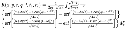
The steps for generating the lubrication gap geometry formed by the thrust collar (TC) and bull gear (BG) track as an essential simulation input are visualized in
Figure 2. The profiles are defined on a 2D section plane (the same as used in
Figure 1) as functions
z of the radius
r (
Figure 2a). For a “straight” profile, i.e., a cone in 3D, it is a triangle:
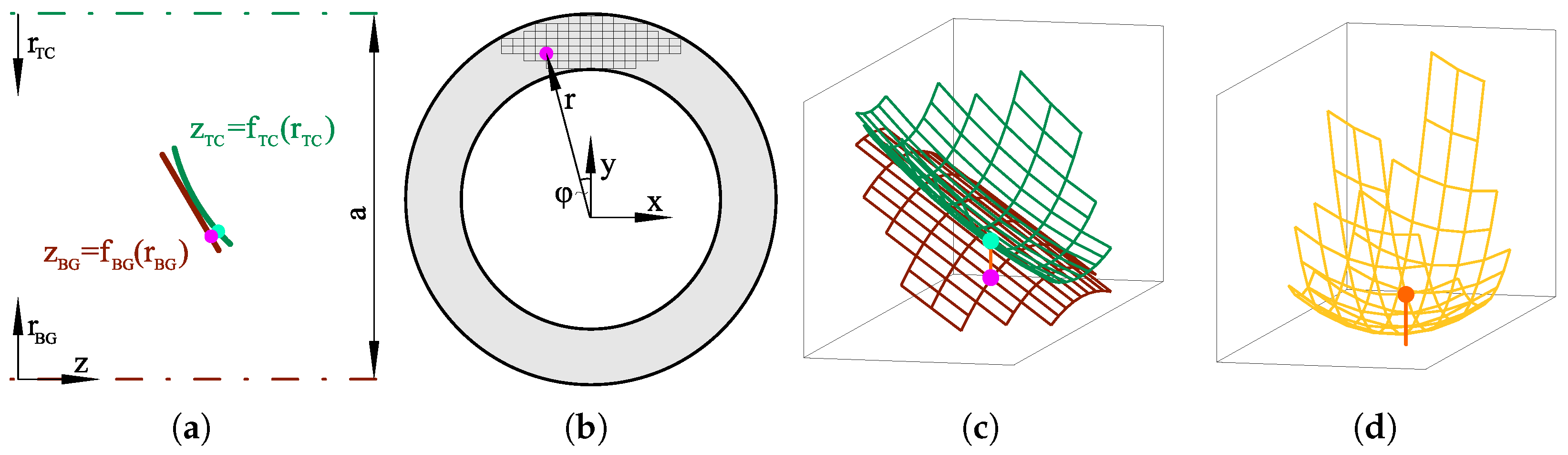
For crowned profiles, the point of contact (POC) needs to be found first:
Sketches used for obtaining these formulas via trigonometric analysis are provided in
Figure 3 as an expansion of
Figure 2a. These functions with polar coordinate input
are evaluated at each position
of the mesh spanning the area overlapped by both tracks after coordinate transformation from Cartesian coordinates (
Figure 2b). In this way, gap height distributions of the thrust collar and bull gear track are obtained as shown in
Figure 2c. The height input to the
Reynolds equation is calculated by subtracting these two profiles to obtain the combined gap height (
Figure 2d).
The track speeds
u in direction
x and
v in direction
y as well as the speed differences
can be calculated at the radial coordinates
by the following equations:
3. Plate Stiffness from FEM
The simplest and fastest way to obtain track deformation under pressure is the use of a
Boussinesq half-space approximation. This assumes that the tracks are not bounded on any side (see the following section) and infinitely deep. This is a reasonable approximation when the pressure build-up is situated relatively far from the edges and when the bodies are thick compared to the interior stress field caused by the surface pressure, as is the case for contacts with smaller radii like roller bearings. When thrust collars are mounted via interference fits, which is standard practice in compressors, they are very thick to prevent gaping of the interface under the eccentric circulating force, which would lead to fretting corrosion [
13]; the issue with plate thickness is not relevant in these cases. When thrust collars are welded to the shaft, which is standard practice in vehicular gearboxes (e.g., [
14]), they can be built considerably thinner, which can lead to issues with the infinite depth assumption. Furthermore, thrust collars bend under load—more so with thinner designs. Most thrust collars do not satisfy the assumptions of the
Kirchhoff plate theory [
13]. For a full analysis of these effects, which would be neglected by the
Boussinesq half-space theory, the finite element method (FEM) is an obvious tool.
A first implementation of plate stiffness into a solver for thrust collars was published in [
15]. In this version, the FE stiffness matrix was obtained from an automatically meshed thrust collar geometry; thus, the meshes of the solid and fluid simulation did not match. Quantities were interpolated between these two meshes via radial basis functions.
In order to simulate highly loaded thrust collars, a different solution method to the
Reynolds equation from the one employed at the time of the mentioned publication was needed for stability when simulating parallel gaps. The newly implemented solution method based on [
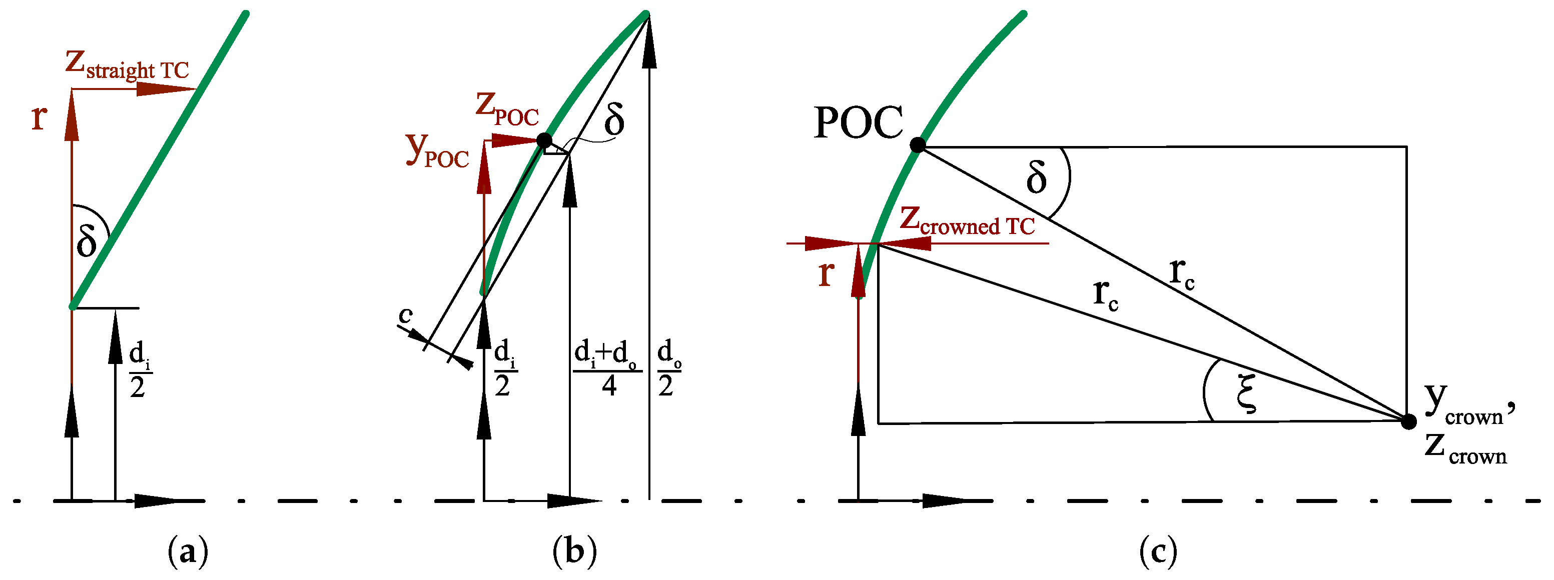
11] requires the solid stiffness at specific fluid mesh points for its relaxation technique. As point loads can not reasonably be interpolated between meshes, the solid and fluid simulation meshes need to match. In order to be able to simulate more complex geometries than hollow cylinders, such as the annular groove used as a grinding run-out shown in Figure 5a, a combination of an automatic mesh generator and manually programmed routines seems optimal.
An initial attempt was made using the simple technique of embedding nodes, as this is readily available in most meshers and does not require special provisions on the users’ side. When embedding nodes, nodes from the fluid mesh are prescribed to the automatic mesh generator for incorporation into its solid mesh. As a quick plausibility check of the obtained mesh, the continuity of the distribution of the maximum depressions resulting from individual nodal loadings can be examined. Neighboring nodes should sink in similarly. The result of this sequence of individual solutions for single point loads is plotted in
Figure 4a in a concatenated form where the square colorization shows the maximum depression at each successively probed node. The results from the mesh using embedded nodes are significantly non-monotonous despite not violating common mesh quality metrics (scaled Jacobian); albeit visual inspection shows a considerably distorted tetrahedral mesh.
Figure 4b shows the expected, physically sound result (from the ultimately implemented method), where there is no oscillation between neighboring points and a small increase towards the outside edge, which lies at the top of this plot. The oscillation on the bottom of
Figure 4b is caused by bad quality elements due to the annular groove as shown in
Figure 5a.
The meshing steps of a refined method are visualized in
Figure 5. First, a base geometry is created as a computer-aided design (CAD) model (
Figure 5a). The prescribed fluid mesh is then cut out from the contact region (
Figure 5b). This resulting geometry is meshed by an automatic mesh generator—this work uses GMSH [
16]. For automeshing, numbers of divisions are prescribed at the edges of the cut out contact region to generate a compatible mesh transition without hanging nodes. Finally, the elements for the cut out region are added via a manually programmed routine (
Figure 5d). A
Cholesky decomposition of the stiffness matrix
of this mesh is calculated, as the FEM equation system
is now solved repeatedly for various right hand sides. By consecutively setting the entries of
, each node of the contact region is loaded with a unit load of 1
and the corresponding displacement of the nodes in the contact region is saved in a matrix
, which can be used the same way as when using the
Boussinesq half-space theory (see, e.g., [
17]) for calculating depression
w at position
due to pressure
p at position
:
All illustrating calculations in this paper are performed on an example gearbox derived from a gear test rig. The details are given in
Table 1. The reduced radius
in this instance is
:
Figure 6 provides a cross-section view of the gap at its minimum height orthogonal to the direction of lubricant entrainment for a
Boussinesq half-space solution (without edge correction; see following section), for equally thick thrust collar and bull gear
and for a combination of a thick bull gear
and a relatively thin thrust collar
.
The results are very close for the thick geometry and the
Boussinesq solution. In this specific example, minor plate bending evens out differences from uncorrected edge effects (following section). For the thin thrust collar, edge loading sets in for the straight track (
Figure 6a). The crowned track is able to compensate; the contact point moves radially (
Figure 6b). There remains some margin before the thin crowned collar would experience edge loading as well; this margin is needed in order to compensate for further angular errors from manufacturing tolerances, etc., which are not input into the geometry generator in this instance.
4. Edge Effect on Half-Space
As the precomputation of from FEM takes a long time and requires a rather large amount of memory not present in most personal computers when using fast direct solvers, a half-space method is preferred for rough dimensioning of thick thrust collars. Plate bending can be approximated by a tilting angle chosen from engineering experience in this case. The tilting angle from bending needs to be added to other sources of misalignment, also required for FEM-based calculations, such as manufacturing tolerances and possibly shaft bending and movement in bearing clearances.
In this case, the effect of the close edge remains to be corrected for. The larger and more extensive depression due to a unit load close to the edge is compared exemplarily to a unit load in the center in
Figure 7.
Reusner [
18] proposed an approximate correction of the edge effect to model an elastic “quarter-space” instead of a “half-space” by mirroring the pressure distribution along the edge to the outside, technically nonexistent region when using half-space theory. This correctly compensates the shear stresses to the same state as in the case of a free surface but doubles the normal stresses in the mirror plane. Exploratory FEM calculations, discussed in depth below, were not satisfactory using this simple
Reusner correction for conditions relevant to thrust collars (Figure 9).
Hetényi introduced an iterative—and therefore computationally expensive—method for correcting this issue [
19,
20]. On this basis,
Guilbault [
21] developed a simplified method which corrects the mirrored pressure
in the
Reusner method by a factor
:
For the standard case of
for steel,
equals 1.39. Calculations by [
21] for general contacts have an error of 9.55% instead of 21.9% without this correction factor.
In contrast to the quarter-space, a thrust collar does not have a planar but a curved edge. The “mirroring method” thus becomes a “radial projection method”. For a radial projection of a point
inside the contact area, its position in a polar coordinate system about the thrust collar or bull gear rotation axis is
The position of the projected point
is found by extending the position vector by twice the distance to the edge of the TC/BG:
The deformation
w of the lubrication gap at position
due to pressure
p at position
can be calculated by (cf. Equation (
16))
C is a distance weighting factor according to the
Boussinesq half-space theory, e.g., described in [
17].
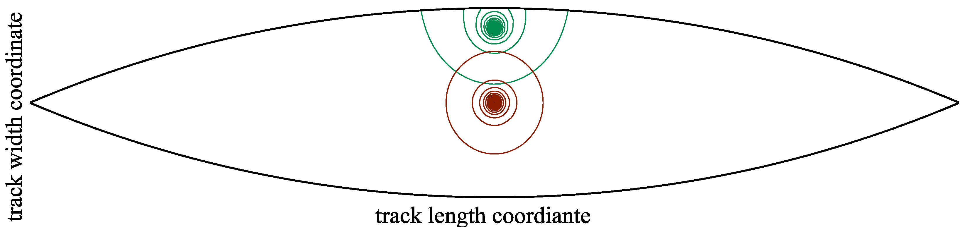
The suitability of this correction method is checked for variously curved edges by comparing it to the results obtained from an FEM model. In one version of this model, a half-space is approximated by a large cuboid, and the pressures are either not projected or projected with or without correction; in another, part of it is suppressed to create an edge close to the pressurized region. An exemplary result can be found in
Figure 8; the region that is suppressed when simulating with an edge is displayed as semiopaque. A variety of
Hertzian pressure distributions relevant to thrust collars with ratios of pressure ellipse width to contact area width of
and ratios of pressure ellipse width to length of
are investigated.
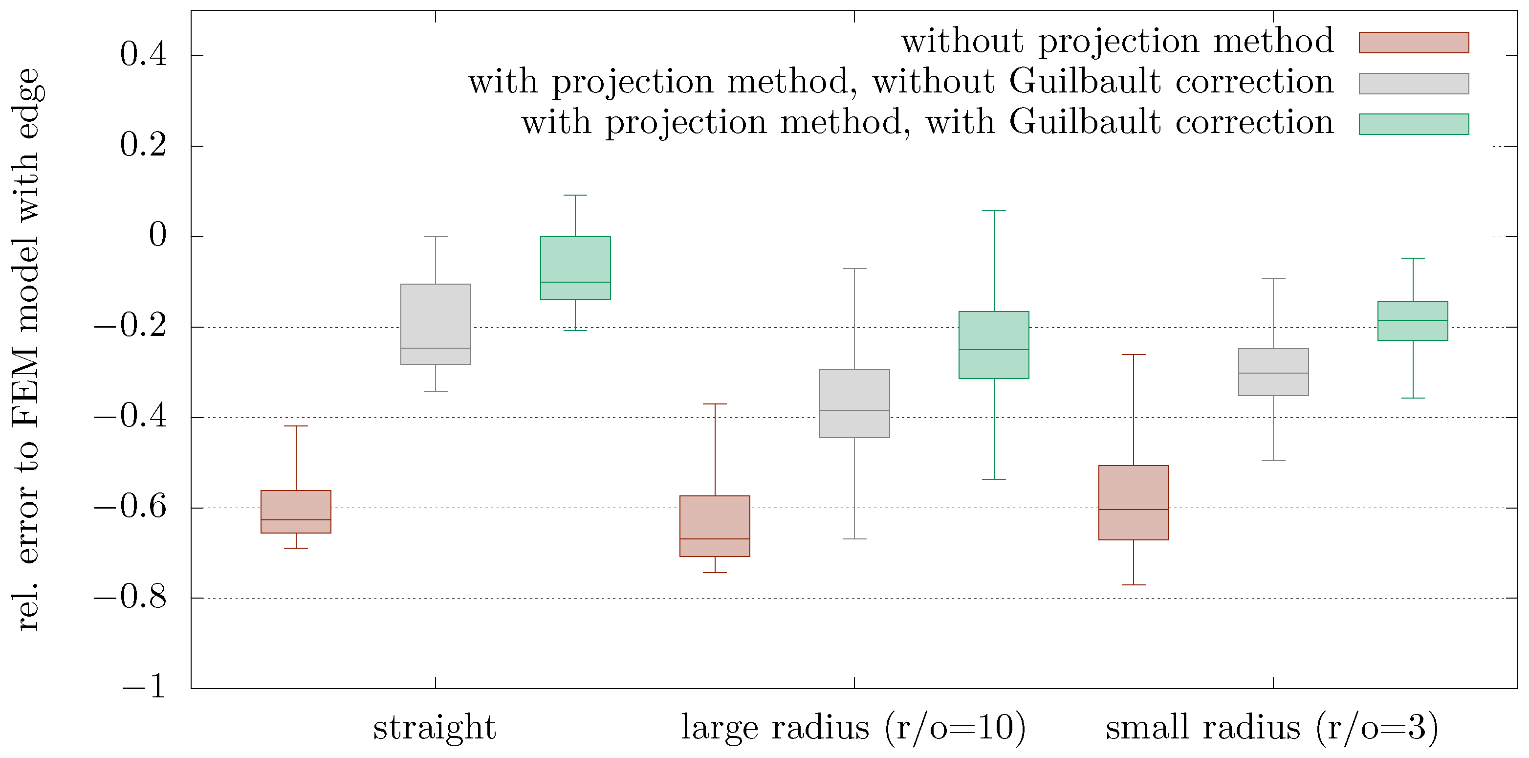
Figure 9 compares the distribution of the relative error of all mesh nodes of the contact area (dashed line in
Figure 8) and all geometrical ratios combined. This summary is chosen as the error is distributed quite uniformly inside the contact area.
The projection method can apparently be used for curved edges, and the correction methods work. However, the error is larger than it is for straight edges.
We choose not to correct the remaining error by using the more expensive Hetényi method, as the FEM method is available for more precise calculations and additionally does not rely on approximations for plate bending.
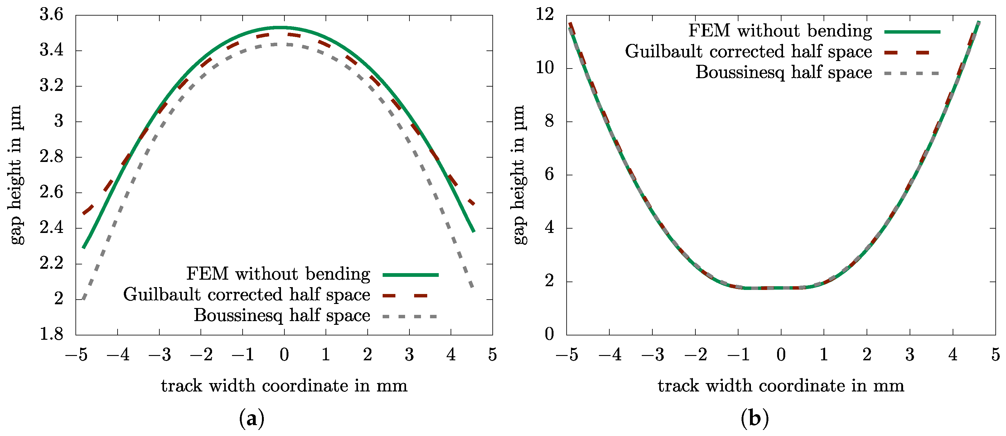
Figure 10 provides a cross-section view of the gap at its minimum height orthogonal to the direction of lubricant entrainment for an uncorrected
Boussinesq half-space solution, for a
Guilbault-corrected half-space solution and for an FEM based solution (model described in
Figure 5) with the back sides supported in order to suppress bending deformation for the example thrust collar from
Table 1.
When the load zone lies far away from the edges, as is the case for this crowning radius needed to compensate for thin plate bending, the edge effect is irrelevant (
Figure 10b). For the straight track (
Figure 10a), as well as for crowned tracks simulated with large angular errors, differences can be found. The
Guilbault-corrected half-space solution is closer to the FEM solution than the uncorrected
Boussinesq half-space, yet there is no exact match.
5. Track Heating on a Circular Arc
Whereas a Cartesian grid (
Figure 2b) is preferred for a finite volume discretization for the solution of the
Reynolds equation, points on the tracks of thrust collar and bull gear do not follow an axis of this grid but move through it on circular arcs. The calculation of track heating thus is more complicated than, e.g., in gears.
Track heating due to a heat flow from the sheared lubricant can be calculated using the
Carslaw/Jaeger solution for a moving point heat source on an infinite heat sink [
22]. The temperature rise
at point
due to a heat flow
q at point
from time
to
is given by:
An analytical solution of the space integral over a grid element is known for horizontal movement along the x-axis [
23]; time integration has to be performed numerically using the substitution
as a treatment of the singularity at
:
R is the heat kernel [
23]:
This can readily be modified for a movement along a circular arc:
Attention should be paid to the surface instead of the heat source moving through the reference system, as is the case in the classical
Carslaw/Jaeger solution, when choosing the integration direction.
Figure 11 shows the track heating due to a point heat source at the center. The heated center point is the hottest; the temperature trace goes through the nodes which have already passed under the heat source.
For a movement along a Cartesian axis, all path integrals are the same, therefore only one integration has to be performed explicitly, and the heat kernels for the remaining nodes can be obtained by shifting the solution. For a movement along a circular arc, a numerical integration has to be performed for each node individually, which is much more time consuming. As the influence of far away nodes is negligible, the path integration can be started at the current time and truncated if the contribution of the past remote point is substantially less than at the current time.
The
Carslaw/Jaeger half-space heating solution inherently has the same issues regarding edge effects as the previously discussed
Boussinesq deformation solution. However, it can be concluded from
Figure 11, that thermal edge effects are much more insignificant than deformation effects, as the thermal trail primarily extends along the 1D trajectory trailing the point source and is hardly orthogonal to it.
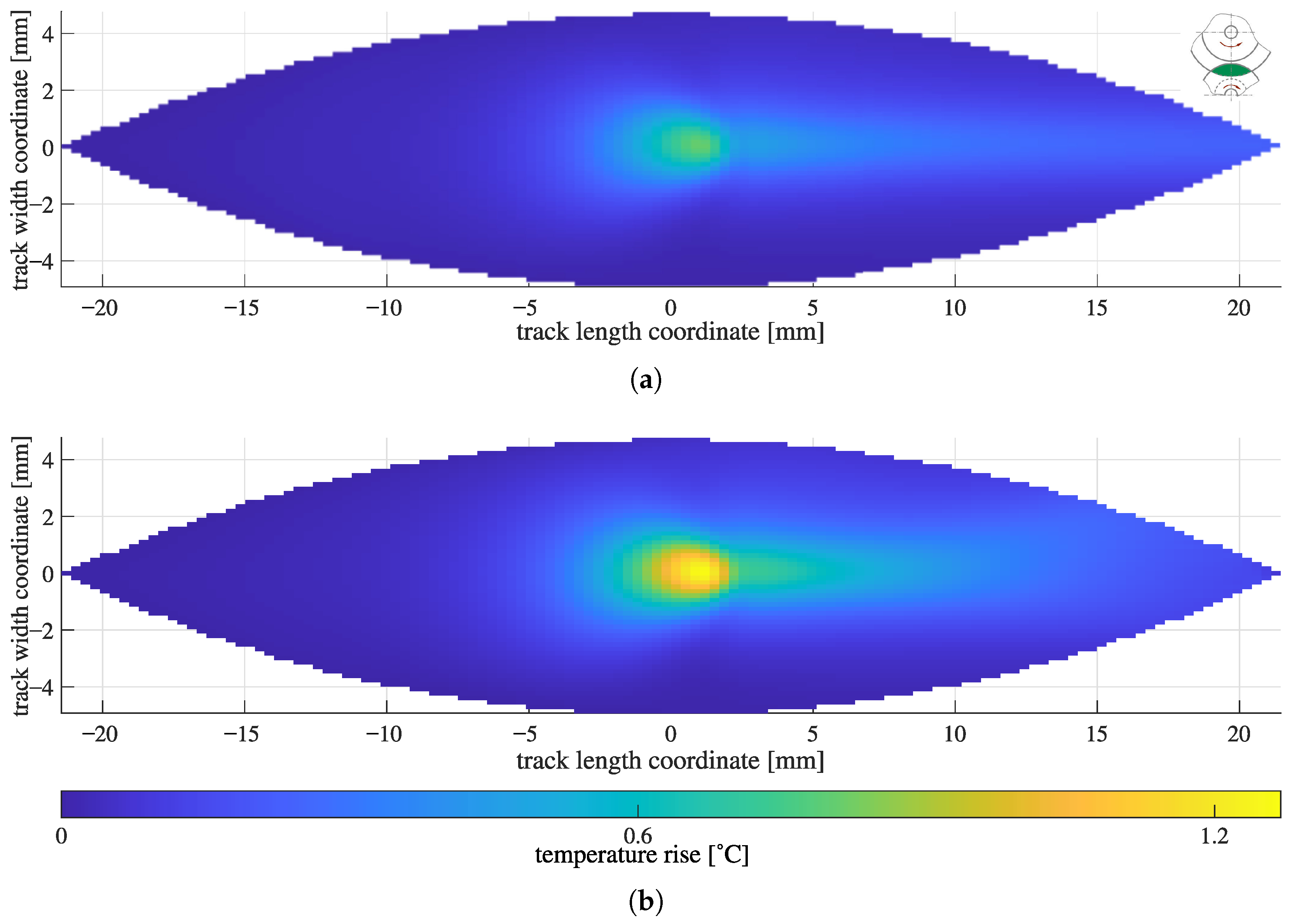
Figure 12a shows the thrust collar track heating of the example thrust collar from
Table 1 for a straight trajectory following the horizontal axis.
Figure 12a shows the thrust collar track heating for a (correct) curved trajectory.
Due to the very high efficiency of thrust collars, in this example with a power loss of a mere 14 , thermal effects could be disregarded. For comparing the mechanisms of the two track heating implementations, this case is advantageous, as only the temperature distribution changes significantly but not the gap height or power loss, which would retroact on temperature. In cases where temperature is relevant, i.e., at very high speeds or in the mixed lubrication regime, one can only see outright differences but not their inherent causes.
Two faint branches can be distinguished in the outlet of the curved trajectory variant (
Figure 12b) compared to a temperature rise just in the middle of the track in the straight trajectory variant (
Figure 12b). As this is in the outlet, the effect on temperature (and gap height) in the loaded zone is minor. The peak temperature is noticeably higher for the curved trajectory variant. This is caused by the greater arc length going through the heated zone in the case of the curved variant. Off the middle, the arc length going through the heated zone is longer for one track (e.g., the thrust collar) and shorter for the other (e.g., the bull gear) when going to a specific point. This reciprocity is not even though and in sum leads to greater temperatures. This can be proven by calculating the temperature rise in a single off-center point of the two tracks passing under the same temperature distribution for curved and straight heating calculations.
7. Conclusions
The improved modeling of thrust collar stiffness leads to vastly different results compared to those which would be obtained by simulation programs not adapted to thrust collars. When edge loading is possible, the results are so disparate that no general error estimate can be given. In order to match simulation and experimental results, the consideration of these effects seems indispensable. Equally, curved trajectories lead to vastly different temperature results compared to straight trajectories, although there are many practical applications where isothermal simulation is sufficient.
The precomputations needed for the FEM-based method are computationally expensive. Theoretically, they could be parallelized without limit by solving the FEM equation system for unit loading of each node at the same time; in practice, this is heavily limited by the available computing capacity. An intermediate method based on correction methods to plate theory, possibly combined with the Hetényi edge correction method, seems worthwhile to pursue.


