Abstract
This study compares the hard turning performance under dual-nozzle minimum quantity lubrication (MQL) using mineral oil and 1-butyl-3-methylimidazolium chloride-based ionic fluids. Key performance indicators, including tool life (based on tool wear), surface roughness, cutting power, cutting temperature, cutting sound, carbon emission, and circularity error, were evaluated to assess manufacturing sustainability. The results revealed that ionic fluid-assisted MQL significantly outperformed mineral oil, improving tool life by 28.75% and reducing surface roughness by 5.58%, attributed to the superior lubrication and cooling ability of ionic fluids. Additionally, after 85 min of machining, the power consumption and carbon emission were greatly reduced under ionic fluid conditions, indicating a lower environmental impact. For precision machining concerns, the ionic fluid proved more favorable, as circularity error under mineral oil conditions was 2.67 times higher than with ionic fluids. The weighted Pugh matrix awarded ionic fluid a higher sustainability score (+7) than mineral oil (+1), establishing it as the superior cooling option for hard turning, enhancing sustainability in machining difficult-to-cut metals.
1. Introduction
Hard turning is a machining process that involves the turning of workpiece with hardness greater than 45 HRC, serving as a viable alternative to traditional grinding methods. This technique has gained traction in various industries, particularly in automotive and manufacturing, due to its efficiency and ability to produce high-quality surface finishes. The evolution of hard turning has been significantly influenced by advancements in cutting tool materials and cooling strategies, which enhance tool life and machining performance [1,2].
The turning process during dry cutting shows a higher temperature, which induces a higher tool wear rate, thus resulting in a shorter tool life, poor surface quality, and larger dimensional deviations [3,4]. Therefore, to control the temperature, many researchers have utilized various cooling techniques such as flood cooling, high-pressure cooling, spray impingement cooling, and minimum quantity lubrication systems. Among these, the MQL technique is effective, efficient, and economical.
The minimal quantity lubrication (MQL) method is extensively employed in hard machining to discharge an air–oil mist coolant to the machining zone. MQL technology is recognized as an environmentally friendly cooling technology for a variety of cutting processes. This approach reduces coolant consumption while enhancing lubrication performance at higher cutting speeds [5,6]. MQL offers benefits such as reduced cutting fluid utilization, cost-effectiveness, environmental affability, increased machining performance, and surface quality [7]. Several articles have demonstrated MQL’s effectiveness in reducing friction at machining interfaces, minimizing adhesion and temperature rise, extending tool life, and enhancing surface quality in conventional cutting processes such as drilling, turning, milling, and grinding [2,8]. The effectiveness of MQL in cooling applications is influenced by the choice of lubricant and operating factors. Using environmentally friendly lubricants, like vegetable-based oils, fatty alcohols, and synthesized esters, helps to reduce the environmental impact of machining processes. Ionic liquids (ILs) serve as a unique aid in lubrication and are widely favored in industries for their exceptional properties. ILs have a melting point below 100 °C and are composed of charged delocalized anions [9]. The use of ionic fluids in hard turning processes offers significant advantages, particularly in enhancing machining performance and sustainability. These fluids improve lubrication and cooling, leading to better surface quality and reduced tool wear. This method not only enhances machining performance but also promotes sustainability by reducing the environmental impact associated with traditional cooling methods [8,10]. Pereira et al. [11] used natural biodegradable oils as an alternative to traditional canola oils in the MQL system, comparing five different alternatives such as sunflower oil, high oleic sunflower oil, castor oil, and ECO-350 recycled oil during the machining of Inconel 718. The result shows that the use of high oleic sunflower oil improved the machining process compared to the currently used canola oil and provided an ecofriendly environment during machining. In another study, Pereira et al. [12] performed a hard turning operation on ASP23 steel under dry and cryogenic environments using both CBN positive and negative inserts and compared the results. It was observed that under cryogenic cooling, negative inserts exhibited a 19.6% improvement in tool life compared to dry cutting, while positive inserts showed a 69.5% increase in tool life compared to dry conditions. In another study, Pereira et al. [13] compared the performance of cryo-MQL cooling with other cooling conditions (wet, dry, MQL, and CO2 cryogenic) in spiral face milling of Inconel 718 alloy. Wet cooling outperformed the other methods, followed by cryo-MQL. Although wet cooling demonstrated the best performance, environment regulation makes cryo-MQL the best sustainable option. Fernández-Abia et al. [14] examined the effects of process variables on cutting forces, shearing, and edge cutting coefficient using a multi-layered carbide cutting tool in the turning of austenitic stainless steel. All three machining forces increased linearly with the feed rate at a fixed cutting speed.
Many studies have used tribometers to evaluate ionic liquids for various material pairs, including steel and steel [15]. ILs are promising lubricant additives for cutting fluid because of their special physiochemical characteristics, which include low volatility, high thermal stability, higher surface adsorption, and increased thermal conductivity. Furthermore, because of their stronger polarity, the use of ILs as a lubricant additive is a key factor in improving tribological interactions between various metal sliding pairs. However, it is interesting to apply ILs as an additive for metalworking fluids for machining applications.
Previously published research indicated that adding ILs to vegetable oils improved machining performance by retarding friction, surface roughness, and tool wear [16,17,18]. Gondi et al. [17] evaluated the performance of three different IL-based cutting fluids (BMIMBF4, BFIMPF6, and BMIM) and reported that ionic liquids performed better than conventional oils in terms of friction and wear reduction. Sabarinath et al. [19] investigated the tribological and rheological properties, along with erosion behavior, of sesame oil enhanced with SiO2 nanoparticles and imidazolium-based ionic liquids. Babu et al. [20] experimented on H13 tool steel using three different cutting conditions (dry, MQL, and IL MQL), and reported that IL MQL gives good results as compared to MQL and dry in terms of reduction in tool wear. Sah et al. [21] examined the impact of halogen-based ionic liquids on jatropha oil by evaluating thermophysical and tribological properties. The study found that tetra butyl ammonium bromide ionic liquids when combined with jatropha oil, enhanced thermal conductivity and specific heat compared to pure jatropha oil. Davis et al. [22] used 1-butyl-3-methylimidazolium hexafluorophosphate ILs with MQL and observed a significant decrease in wear. Furthermore, ILs resulted in lower surface roughness than dry machining. Srinivas et al. [23] prepared a neem oil-based emulsion by the addition of 2% wt of trihexyltetradecyl phosphonium bis (2,4,4-trimethyl pentyl phosphinate) ionic liquid and observed that the produced emulsion contributed to increased performance in axial force and surface roughness during the drilling process.
Based on the literature survey, it can be summarized that the use of ionic liquids as additives to metalworking fluids has not been extensively explored. The synthesis of ionic liquids as additives to mineral oil for machining coolant applications has not yet been reported, even though mineral oil is widely used as a cutting fluid in the metal machining industry. Additionally, commercially available ionic liquids are predominantly used for synthesizing ionic liquid-based coolants. However, no research has reported the process of ionic liquid synthesis specifically for machining coolant applications.
In recent years, dual-nozzle MQL has gained popularity over single-nozzle MQL due to its superior cooling and lubrication capabilities. Nonetheless, its application with ionic liquid coolants in hard turning is noteworthy and unique. Based on these novel aspects and identified research gaps, the current study focuses on the synthesis of ionic liquids and ionic liquid-based coolants for the hard turning of AISI D2 steel using dual-nozzle MQL. Machining responses, such as tool life (based on flank wear), surface quality, power consumption, cutting temperature, cutting sound emission, carbon emissions, and circularity error, are compared between mineral oil and ionic liquid-based coolants (ionic fluid) to identify the most sustainable machining process.
2. Synthesis of Cutting Fluids and Experimental Details
2.1. Synthesis of Ionic Liquids
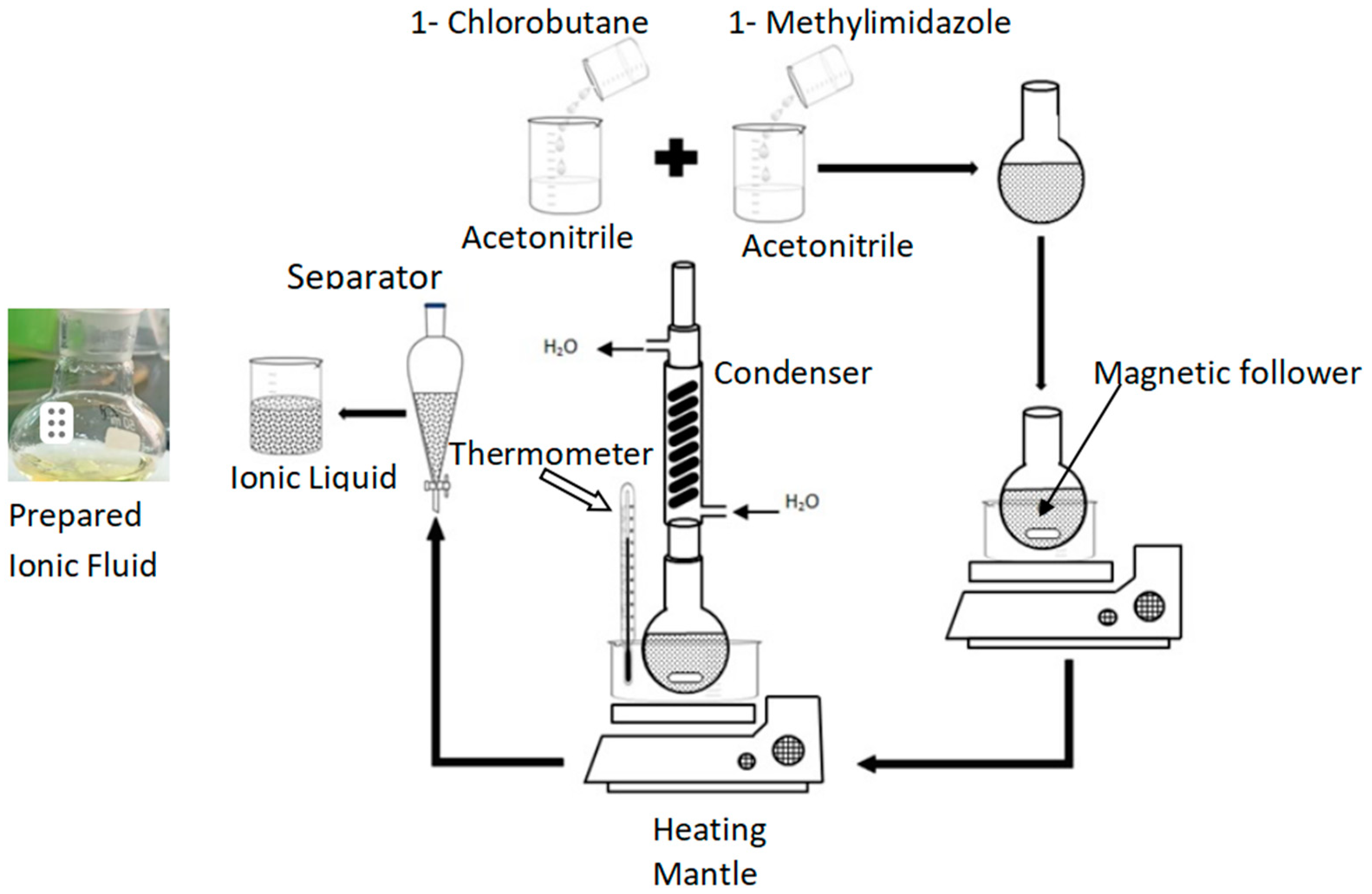
The ionic liquid synthesis was carried out using a two-step methodology as shown in Figure 1. Initially, an equimolar mixture of 1-chlorobutane (n-BuCl) and n-methylimidazole (n-MIM) was prepared by adding 5.23 mL of n-BuCl and 3.5 mL of n-MIM to 50 mL of acetonitrile. The resulting solution was stirred at room temperature for 20 min. Further, the mixture was refluxed at 80 °C for 2 days. Subsequently, the solution was evaporated using a rotary evaporator to obtain the ionic liquid. Further, to confirm whether the synthesized ionic liquid was 1-butyl-3-methylimidazolium chloride or not, 1H-NMR testing was performed using an NMR spectrometer (JNM-ECZ400S/L1:400MHz, JEOL). The 1H-NMR spectrum of [C14mim][Cl] in CDCl3 used as a solvent is shown in Figure 2 as 77.88 (3H, triplet), 18.82 (2H, doublet), 136.73 (2H, doublet), 12.91 (1H, singlet), 121.89 (3H, triplet), and 128.41 (1H, singlet). The obtained data for the synthesized ionic liquid in this test are like the literature [24]. Therefore, the synthesized liquid is 1-butyl-3-methylimidazolium chloride.

Figure 1.
Synthesis of ionic liquid.
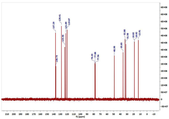
Figure 2.
1H-NMR spectra of the developed ionic liquid.
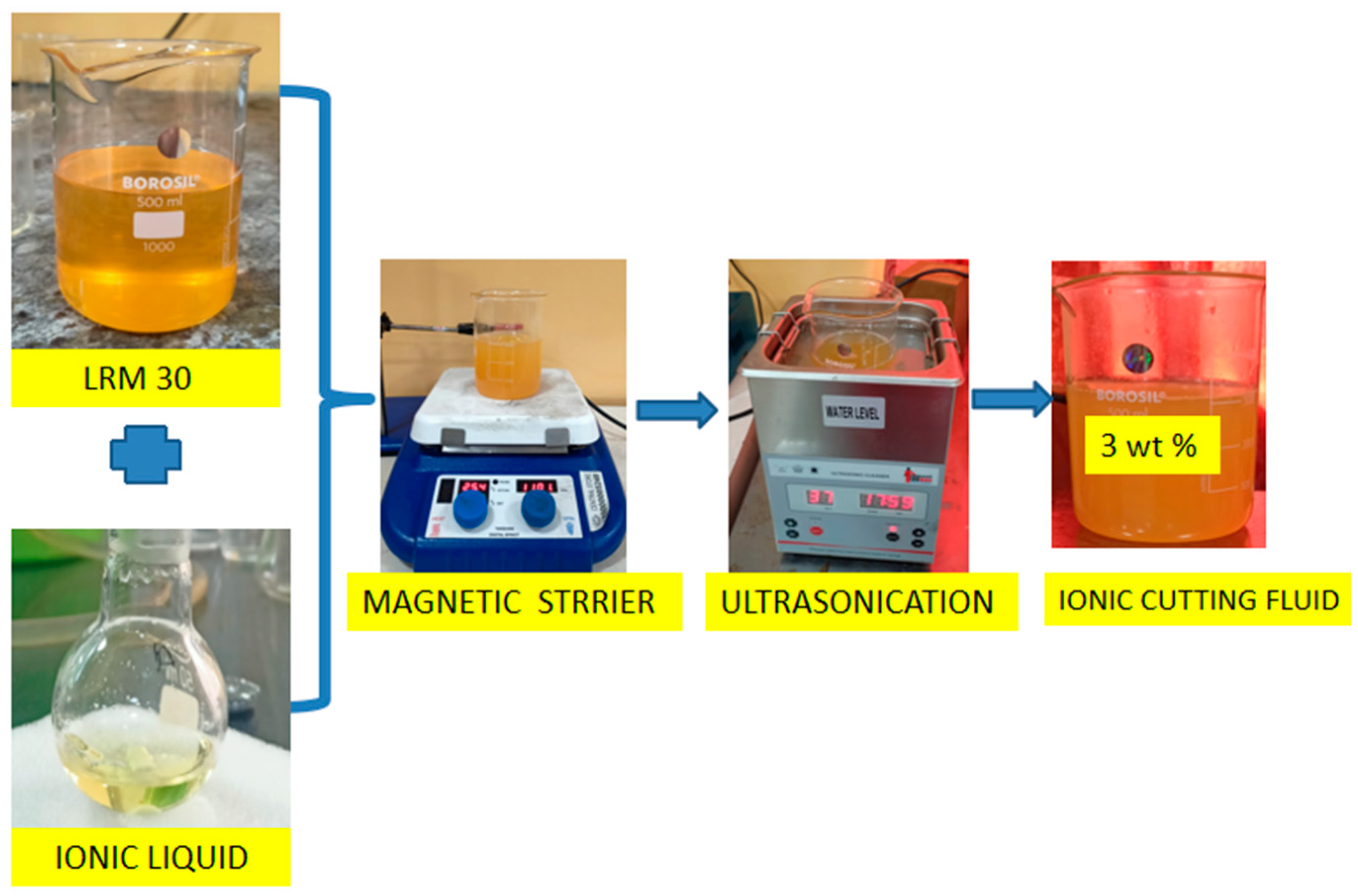
2.2. Ionic Liquid-Based Cutting Fluid Preparation
A two-step methodology was implemented to prepare the ionic liquid-based new cutting fluid. The preparation methodology is shown in Figure 3. Initially, 500 g of mineral oil (LRT 30, Supplied by DROPSA, Vimodrone, Italy) was placed in a glass beaker and stirred using a magnetic stirrer at a speed of 1200 rpm. The 15 g (3 wt% concentrations) of ionic liquid was then gradually added to the base oil, and stirring continued for 2 h at the same speed. Further, ultrasonication was performed for 3 h. The sonication process utilized ultrasonic pulses of 50 W power and a frequency of 40 kHz. In this way, the ionic liquid coupled with cutting fluid was prepared. Further, the stability, viscosity, and thermal conductivity of the newly developed cutting fluid were measured. The synthesized cutting fluid exhibited stability for up to 96 h, after which sedimentation of the ionic liquid began. Using a Brookfield viscometer (Model LVDV-1), the viscosity of the cutting fluid was determined at room temperature (27 °C) and found to be 32.46cP. Its thermal conductivity was assessed using a Transient Hot Wire instrument (Model THW-12), yielding a value of 0.173 W/mK.
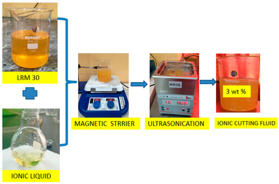
Figure 3.
Schematic view of preparing ionic liquid-based cutting fluid.
2.3. Experimental Details
In this research, two different cutting conditions (mineral oil and ionic fluid) were used through dual-nozzle MQL in turning hardened tool steel (AISI D2 of diameter 48 mm and machining length 200 mm). A CNC turning machine, model DX 2004A (Jyoti CNC Automated Ltd., Rajkot, India), was used for the turning tests. LRT 30 is an industrial-grade mineral oil while ionic fluid is a mixture of 3 wt% of 1-butyl-3-methylimidazolium chloride ILs and LRT 30. The comparison of both cooling technologies was assessed using increasing machine time with fixed cutting parameters (a = 0.15 mm, f = 0.06 mm/rev, v = 100 m/min). A CVD carbide tool, coated with TiCN/Al2O3 and with an ISO signature of CNMG 120408, was used for turning. Its geometry included a 0.8 mm nose radius, a 95° approach angle, a −6° back rake angle, a 0° neutral clearance angle, a 0° side relief angle, a 6° end cutting edge angle, and an 80° included angle. A dual-nozzle setup of MQL was used to deliver coolant into the cutting zone. The lubricant flow speed of both nozzles was equal to 50 mL/h with an air pressure of 6 bars. The first nozzle was oriented from the flank face direction (30° from the tool holder axis) and the second nozzle was placed vertically to-wards the rake face or cutting zone. The nozzle distance from the heat source (tool–workpiece contact) was fixed at 25 ± 3 cm. The experimental facilities are shown in Figure 4.
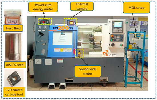
Figure 4.
Experimental facilities.
The machinability performance under both cooling situations was examined using results of tool wear, surface quality, cutting power, cutting temperature, cutting sound, carbon emission, and circularity error. An Olympus STM6 optical microscope was used to measure wear length, while surface roughness was recorded by a roughness tester (Mitutoyo made Surface SV-2100). The cut-off value for surface roughness measurement was set to 0.8 mm. For both measurements, the mean of five readings was considered. An FLIR thermal camera was used to monitor temperature variations in the cutting zone, with the maximum recorded temperature considered for analysis. The experimentally determined emissivity value of 0.81 (using the black tape method) was set in the thermal camera before the final measurement. A Fluke-made noise meter was used to measure the noise emission, and a three-phase energy meter was used to record the cutting power value. Circularity error was evaluated using a Mitutoyo coordinate measuring machine.
3. Results and Discussion
The results of flank wear (VBc), surface roughness (Ra), power consumption (Pc), Temperature (T), cutting noise (Cn), and carbon emission (Ce) concerning machining time are displayed in Table 1.

Table 1.
Measured results of responses studied.
3.1. Tool Wear Assessment
The tool wear of the turning tool was analyzed based on the tool flank wear criterion (VBc = 0.3 mm). Flank wear increases with machining time under booth cooling scenarios as displayed in Figure 5. This result may be attributed to uninterrupted use, leading to higher friction and heat generation, thereby accelerating tool flank wear. Under both cooling scenarios, abrasive marks are produced due to rubbing of hard phases, such as the austenite in AISI D2 steel, against the tool tip. Moreover, as cutting progressed, the cutting load and temperature increased, leading to micro-chipping of the cutting edge, which eventually resulted in tool tip fracture, as shown in Figure 5. Considering the flank wear criterion (VBc = 0.3 mm), the tool life under ionic fluid was found to be approximately 103 min, which is 28.75% longer than that of the mineral oil (80 min). Ionic fluids excel in reducing friction between materials, offering high specific heat capacity to effectively dissipate heat from the machining zone to the environment. Their ionic structure forms a barrier on surfaces, minimizing abrasion, enhancing heat conductivity, and delaying machining wear [22,25]. Moreover, due to their ionic structure, ionic fluids exhibit a strong propensity for adsorption and rapid surface interaction, forming a robust, protective barrier between mating surfaces of tool and workpiece. This ionic shielding effect minimizes direct metal-to-metal contact, consequently reducing wear. Additionally, the superior thermal conductivity of ionic fluids facilitates effective heat transfer, thereby diminishing abrasive wear within the cutting region and prolonging tool life [22]. In the tool life estimation, as the cutting process continues, the tool’s flank face is constantly rubbed by hard particles (C, Cr, Si, etc.) present in the work material. This phenomenon leads to micro-abrasion, which progressively erodes the tool surface and accelerates flank wear [26]. Once the wear exceeds the limiting value of 0.3 mm, the tool coating layers, along with parts of the carbide substrate, are removed from the tool tip, resulting in catastrophic tool failure under both cooling scenarios. During the initial machining stages, abrasive scratches were noticed followed by adhesion between the tool and workpiece portion, eventually leading to tool-tip breakage.
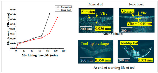
Figure 5.
Obtained flank wear under mineral oil and ionic fluid conditions.
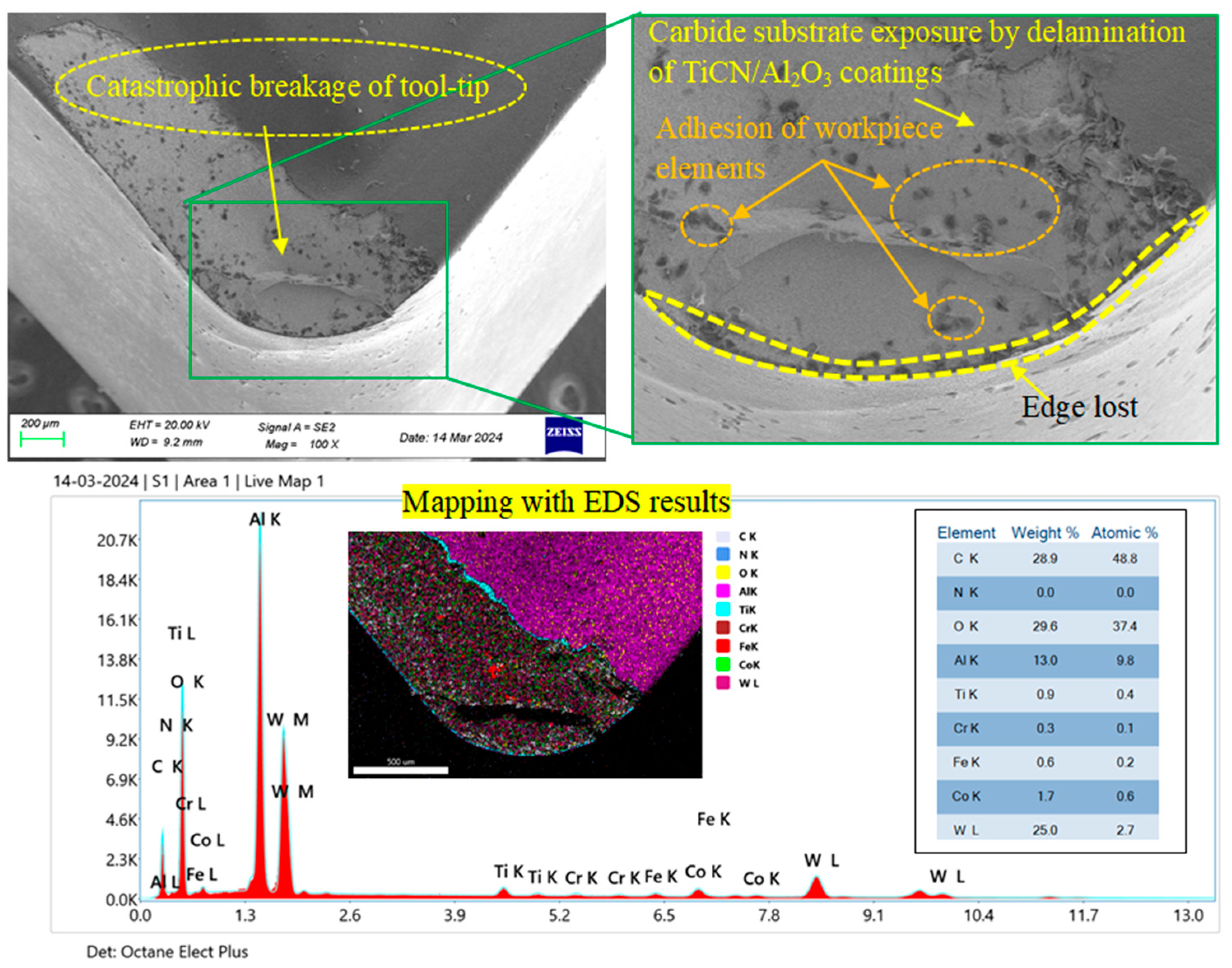
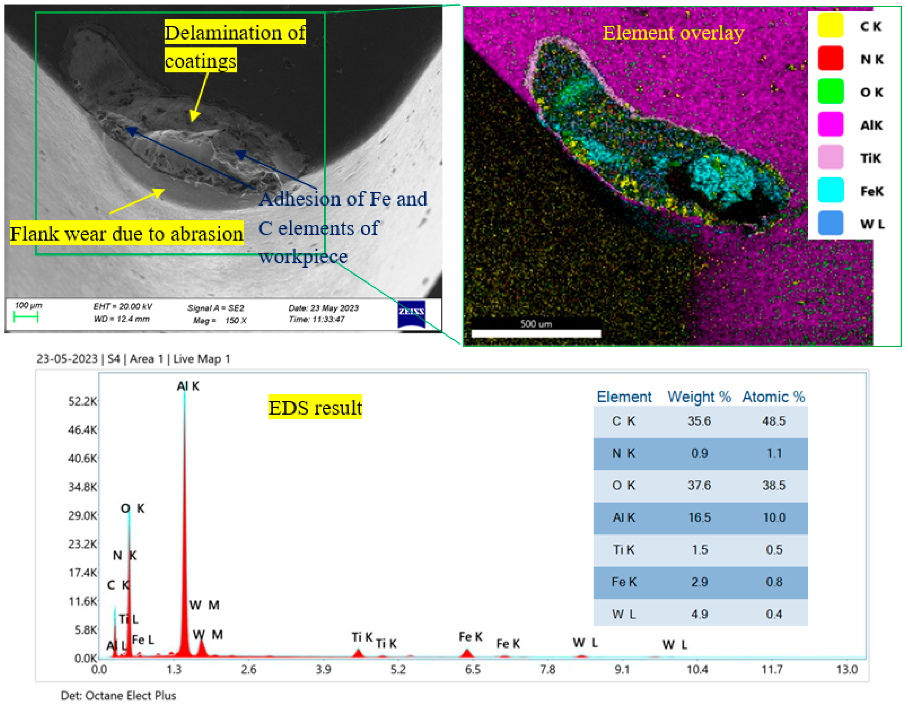
The mechanics of flank wear were analyzed using SEM, mapping, and EDS analysis of the tool tip at the end of its tool life, as shown in Figure 6. The SEM image revealed catastrophic tool-tip failure caused by high stress and elevated temperatures. The coating layers (TiCN and Al2O3) were removed, exposing the carbide substrate, and significant tool edge loss was observed. Mapping results further confirmed the removal of coating layers. The SEM image also indicated the adhesion of workpiece elements on the worn tool rake surface. Workpiece components like Cr, Fe, and C were found by EDS analysis on the worn tool surface; this was probably caused by adhesion under extreme heat and stress. Furthermore, the exposure of the carbide substrate near the end of the tool’s life was confirmed by the presence of cobalt and tungsten carbide on the broken tool tip.
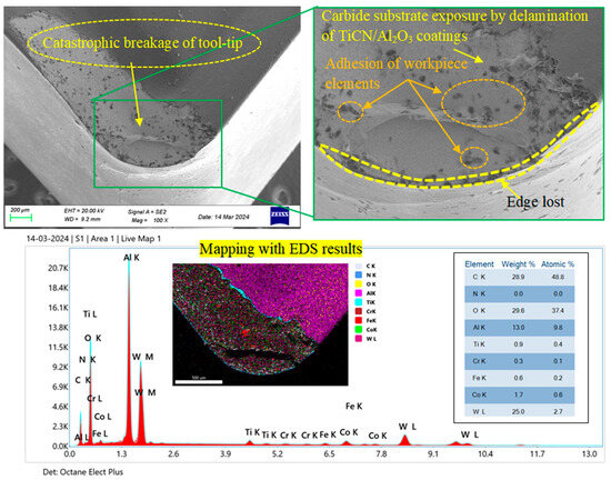
Figure 6.
SEM, mapping, and EDS test results of failure tool tip under mineral oil conditions.
Similarly, as shown in Figure 7, SEM, mapping, and EDS analysis were carried out on the tool tip under ionic fluid at the end of tool life. The carbide substrate (W) was visible in the SEM image, which conformed that the coating layers had been removed from the tool tip. Mapping and EDS results further revealed the adhesion of workpiece elements, such as Fe and C, on the tool tip, indicating the occurrence of adhesion wear as the dominant mechanism at the end of the tool’s working life.
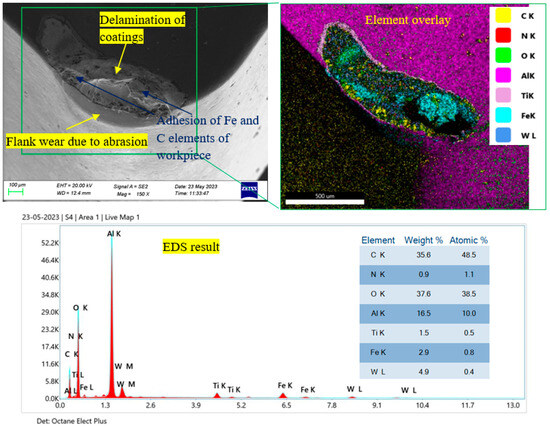
Figure 7.
SEM, mapping, and EDS test results of failure tool tip under ionic liquid conditions.
3.2. Surface Roughness and Surface Texture Assessment
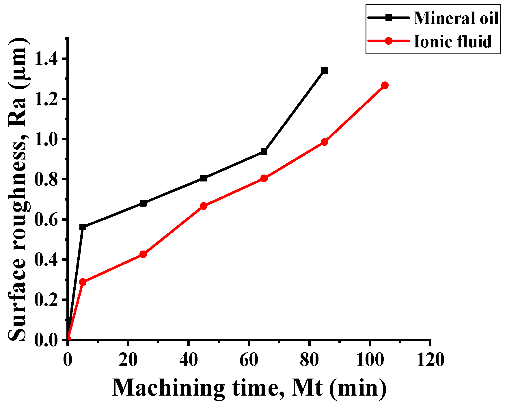
Surface roughness was assessed based on roughness criteria of 1.6 µm [8]. At the end of the tool’s life, the surface roughness was acceptable under both cooling conditions. The surface roughness under both cooling conditions was snowballing with cutting time due to growing temperature and tool wear (Figure 8). Considering the tool failure criteria (VBc = 0.3 mm), the surface roughness under ionic fluid conditions was found to be 5.58% lower than mineral oil. After 85 min of machining, the surface roughness under ionic fluid was 26.60% lower than mineral oil. With the use of a dual jet nozzle system, the lubricant seeps deeper into the work–tool interface, hence there is declining friction between workpiece and tool resulting a significant reduction in cutting temperature and surface roughness. Due to these reasons, the Ra was found to be lower for hard turning. Furthermore, the ionic fluid comprises positively charged cations and negatively charged anions, which interact to form a lubricating molecular film between the tool and workpiece. This ultra-thin boundary layer minimizes direct contact thus effectively minimizing friction in the cutting zone. As a result, surface roughness is considerably diminished, leading to improved machining performance. Babu et al. [20] conveyed that the adhesion of the ionic fluid components within the machining zone played a crucial role in expressively lowering the coefficient of friction. This fall in friction coefficient directly contributed to an improvement in surface quality by minimizing the roughness of the machined component.
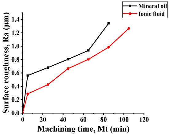
Figure 8.
Machining time vs. surface roughness comparison.
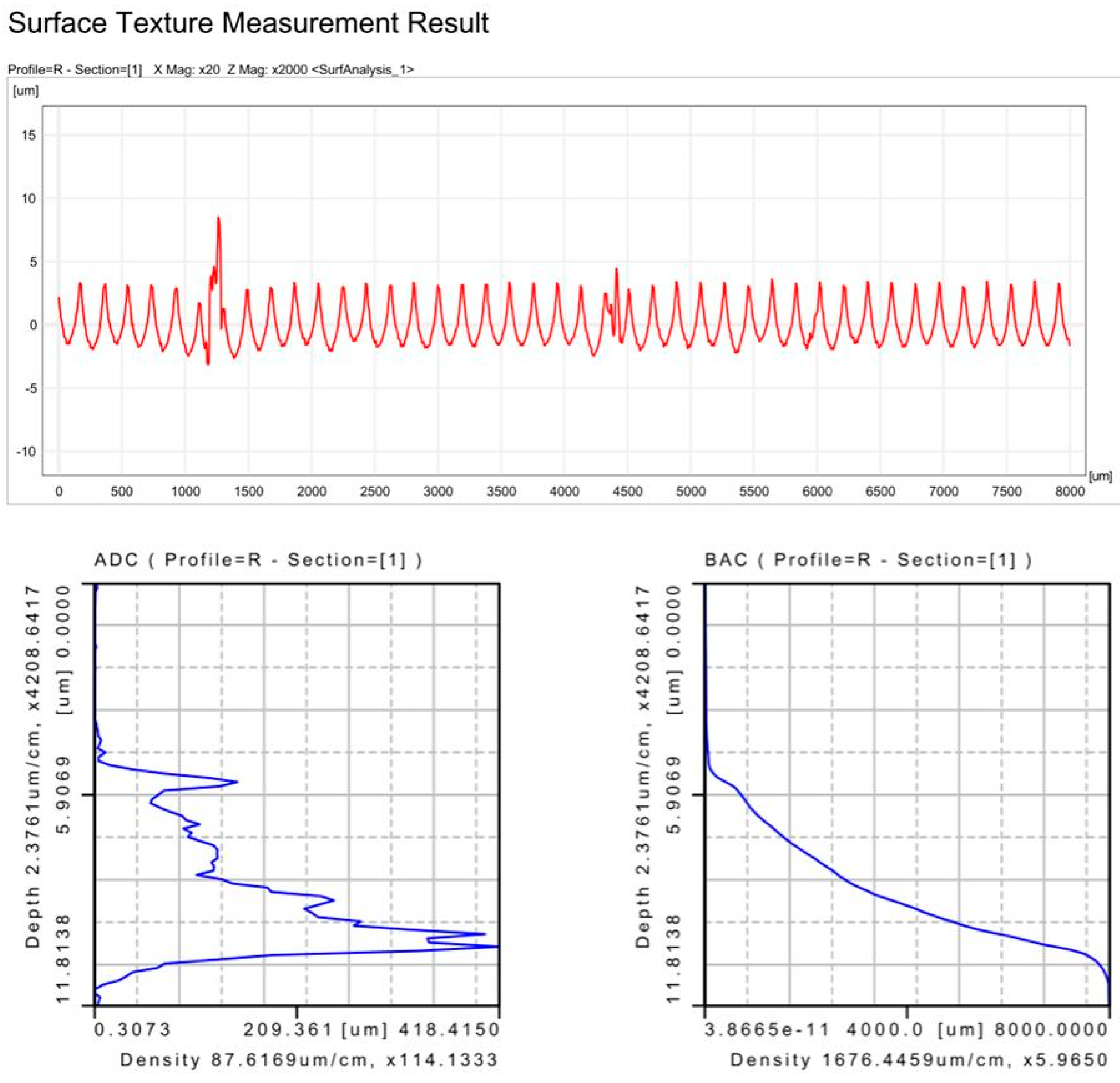
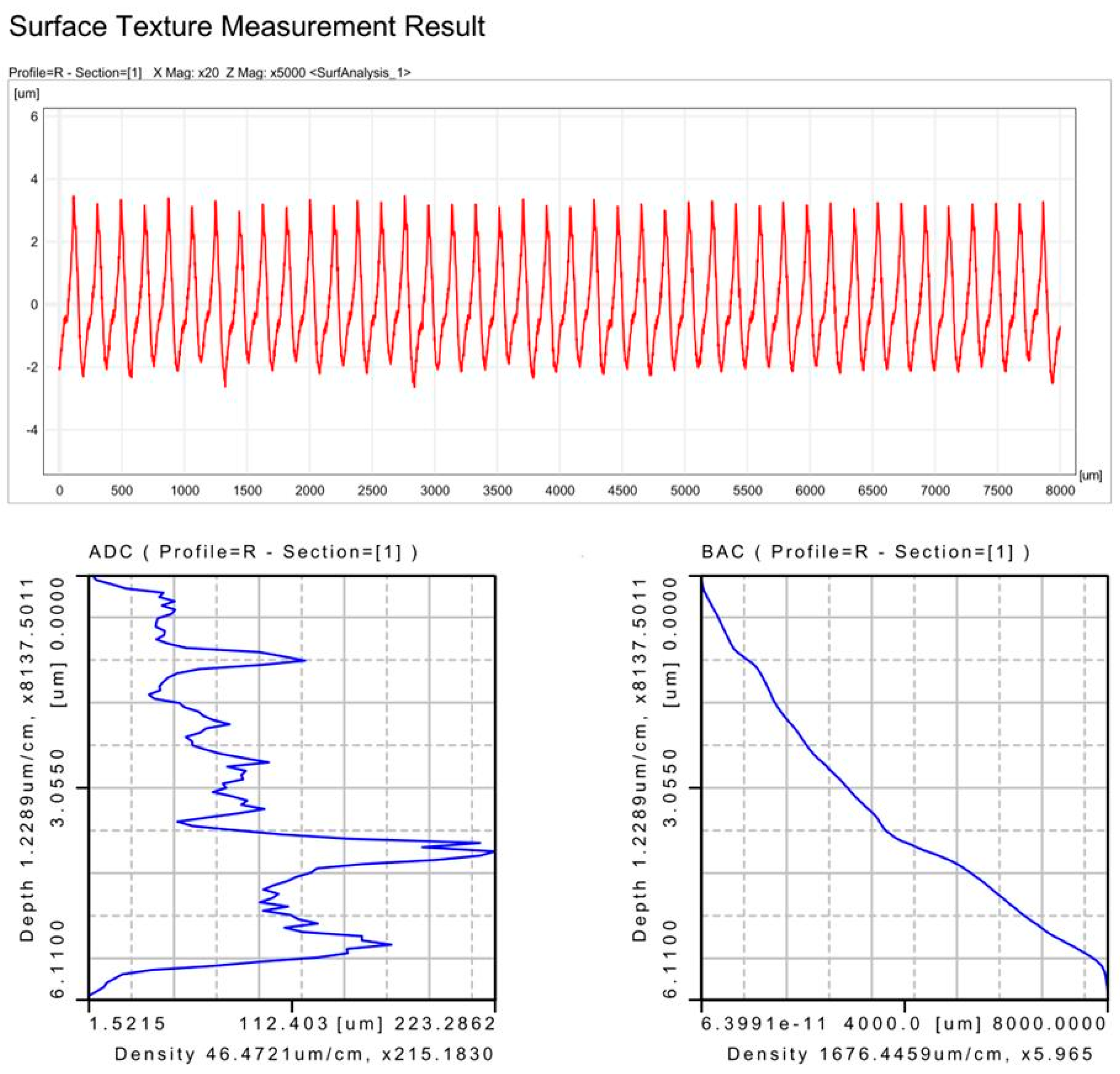
Moreover, the surface texture of the machined surface under both cooling conditions was studied as displayed in Figure 9 and Figure 10, respectively. Under both cooling conditions, the surface texture has uniform spacing, but in mineral oil conditions, the surface profile curve is increased suddenly due to the presence of chip debris on the surface. The ADC (amplitude density curve) under both cooling conditions is non-symmetric showing non-uniform variations in roughness heights. This is probably due to the breakage of the tip of the tool at the end of its working life under both cooling conditions. Moreover, the BAC (bearing area curve) under both cooling conditions does not follow the S-shape resulting in more variations in surface roughness throughout the measuring length.
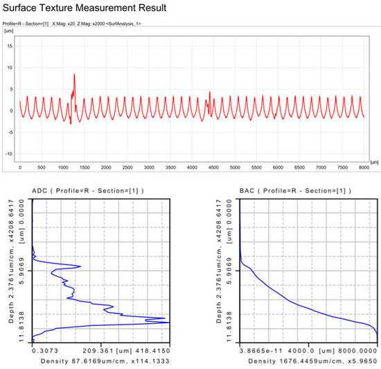
Figure 9.
Surface texture profile of test sample under mineral oil conditions.
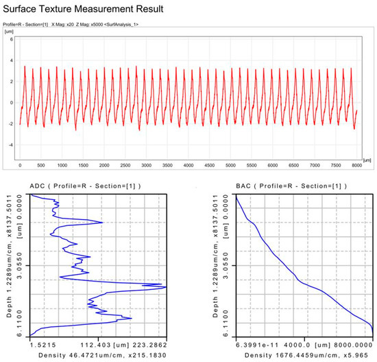
Figure 10.
Surface texture profile of test sample under ionic fluid.
3.3. Cutting Power Consumption Assessment
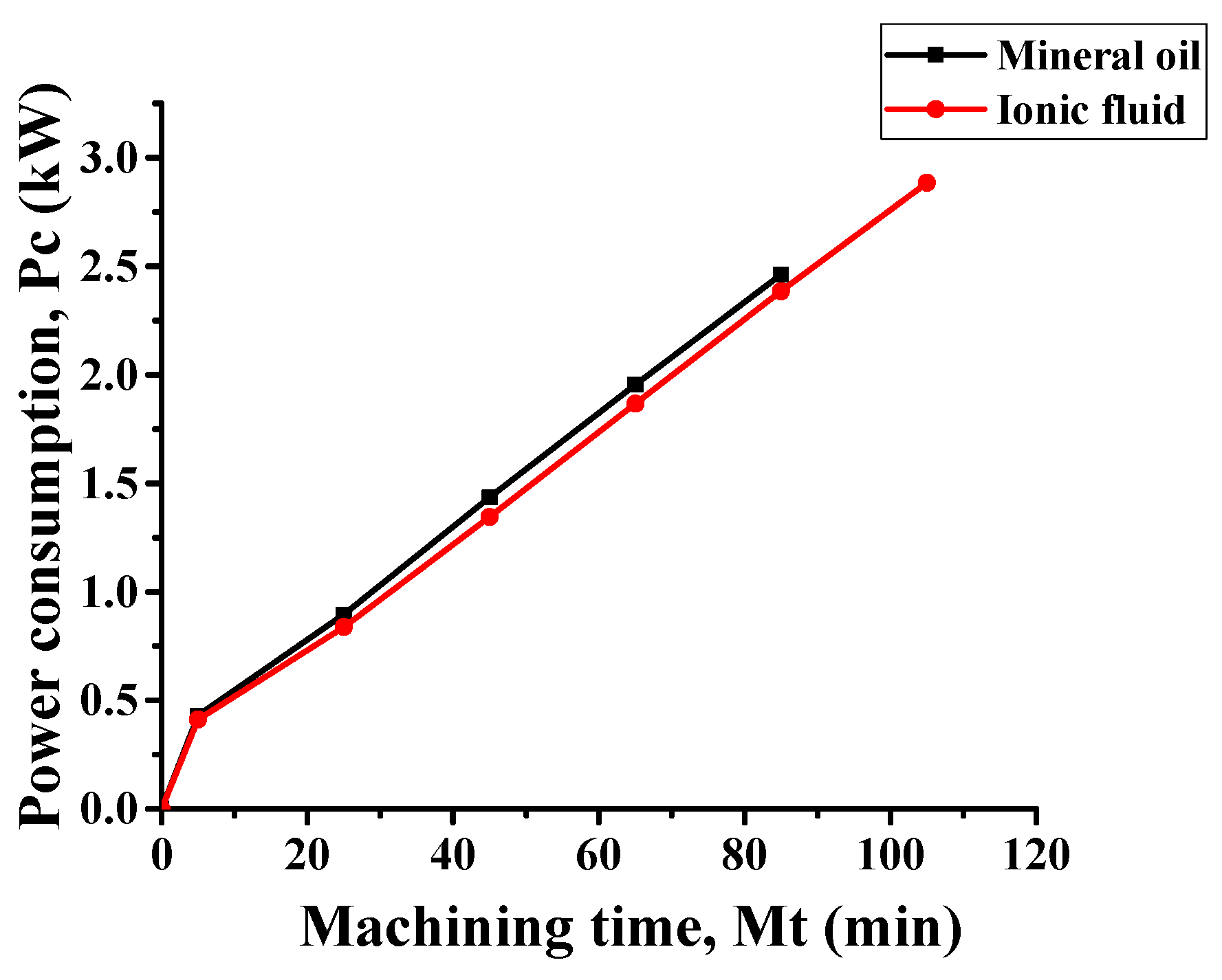
Power consumption in machining is one of the important aspects that affect the total machining cost of a product. Furthermore, it affects the generation of carbon footprint during machining. However, to achieve sustainable machining, power consumption should be as low as possible [27]. Power consumption under both cooling conditions increased with machining time (Figure 11). However, as the working life of the tool under ionic liquid was higher, higher power consumption as compared to mineral oil was noted at the end of the tool’s life. The decrease in cutting power consumption under ionic fluid conditions can be attributed to the formation of an ultra-thin, low-shear lubrication film at the tool–workpiece interface. This protective layer minimizes direct contact, effectively lowering friction and facilitating smoother cutting. As a result, machining resistance decreases, leading to a significant reduction in power consumption [28]. After 85 min of machining, the power consumption under ionic fluid conditions was found to be 3.12% smaller than that of mineral oil.
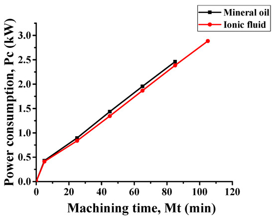
Figure 11.
Machining time vs. power consumption comparison.
3.4. Cutting Temperature Assessment
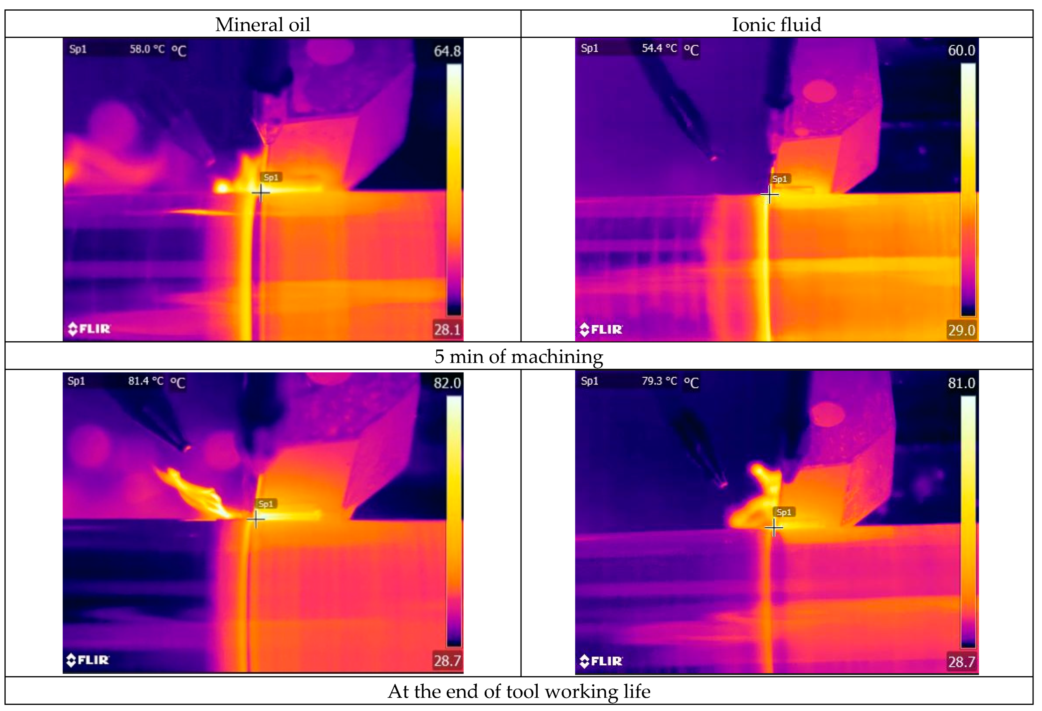
The temperature increased with machining time, as depicted in Figure 12. Thermal images captured under both cooling conditions, recorded after 5 min of machining and at the end of the tool’s working life (determined by a tool wear criterion of VBc = 0.3 mm), are presented in Figure 13. With an increase in time, the friction between the tool and workpiece increased as a result temperature increases with machining time. After 5 min of machining, the cutting temperature under ionic fluid was found to be 6.20% lower than mineral oil. Similarly, after 85 min of machining, the tool life under ionic fluid was observed to be 9.4% lower than mineral oil. However, a significant amount of reduction in temperature was noticed with the use of ionic fluid in comparison to mineral oil. The ionic liquid molecules, densely packed within base oil, create a protective thin film at the tool–workpiece interface. This layer effectually lessens abrasion, leading to a considerable decrease in temperature [29]. According to Syahir et al. [30], the enhanced wettability characteristics of ionic cutting fluid facilitates smooth interaction between the surfaces and promotes rapid heat dissipation from the cutting zone thus producing lower temperature during hard part turning. Research by Banbam and Gajrani further confirms that adding ionic liquid to base mineral oil improves heat removal by promoting the evaporation of fine droplets, which reduces machining temperatures [17].
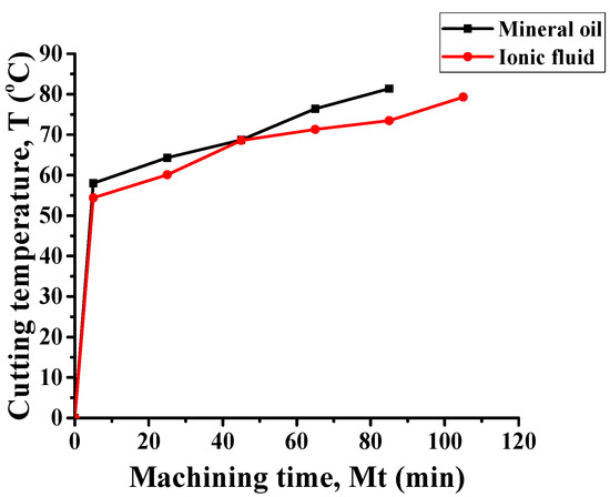
Figure 12.
Machining time vs. cutting temperature comparison.

Figure 13.
Obtained cutting temperature under mineral oil and ionic fluid conditions.
3.5. Cutting Noise Assessment
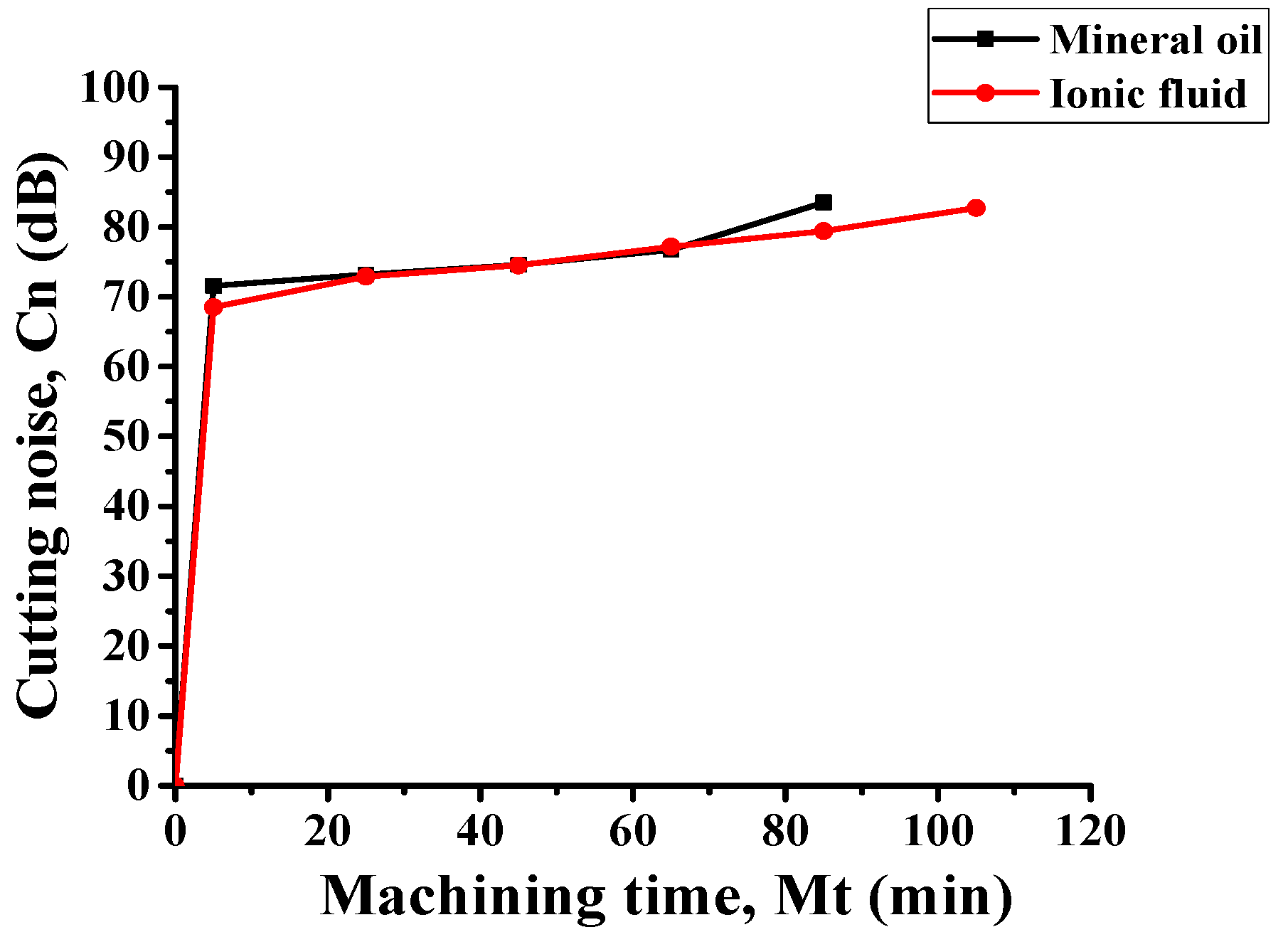
In recent years, noise emission during machining has also been a challenging aspect of achieving sustainable manufacturing. Many researchers have recommended controlling the noise emission within 85 dB to avoid any severe hearing loss to the operators while doing the machining [31]. In the current study, the cutting noise grows with machining time due to the enlarging contact region between the workpiece and tool. With the progress of machining time, the tool wear increases; thus, the contact region between the tool and workpiece increases resulting in more friction and thus more noise generation. At the end of the tool’s working life, noise emissions were recorded as 83.5 dB under mineral oil conditions and 82.7 dB under ionic fluid conditions, both remaining below the 85 dB threshold. Figure 14 illustrates that the noise levels for both cooling conditions are almost identical.

Figure 14.
Machining time vs. cutting noise comparison.
3.6. Carbon Emission Assessment
Nowadays, low carbon emissions during machining are desirable to meet the global demand. There are many sources for generating carbon emissions in a machining plant. In the current study, the carbon emission measurement while cutting was estimated. The carbon emission during cutting is greatly influenced by energy consumption. However, for a complete cycle of machining, the carbon emission is estimated by multiplying the energy consumption by the carbon emission factor. The carbon emission factor for the Indian power grid is taken as 0.71 Kg CO2/KWh [32]. The estimated cumulative carbon emission after each interval is shown in Table 1. The carbon emission grows with machining time as energy consumption increases with cutting time (Figure 15). Under ionic fluid conditions, the carbon emission was relatively less than mineral oil due to the easy shearing of material and thus lesser energy consumption. After 85 min of machining, the carbon emission under ionic fluid conditions was 3.1% lower than mineral oil. Although the % difference is lower, for mass production, ionic fluid-assisted machining may be more favorable than mineral oil in machining hardened AISI D2 steel.
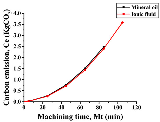
Figure 15.
Machining time vs. carbon emission comparison.
3.7. Circularity Assessment
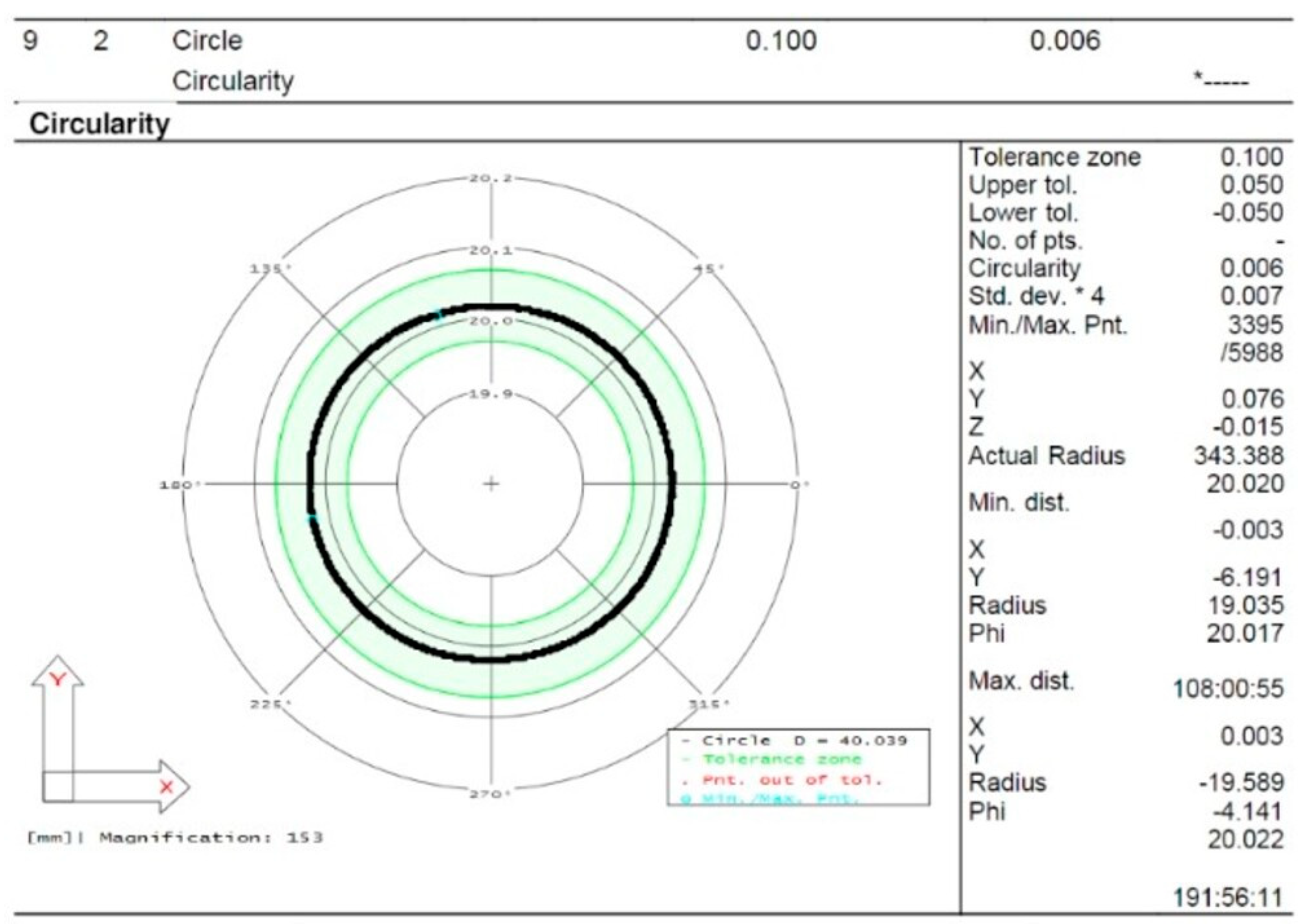
Precision machining is one of the most important outputs for sustainable manufacturing as it directly affects the applicability of the finished product [32]. In the current study, circularity measurement was performed at the end of the tool’s working life. The circularity under mineral and ionic fluid conditions was found to be 0.022 mm (Figure 16) and 0.006 mm (Figure 17), respectively. However, the circularity error under mineral oil conditions was 2.67 times higher than ionic fluid. This might have happened due to the better lubrication capability of ionic fluid than mineral oil. Moreover, at the end of the tool’s working life under mineral oil, the contact between the tool and workpiece was not uniform throughout the run due to more auxiliary wear by the removal of thicker material from the tool edge resulting in higher circularity error. Under mineral oil conditions, a lobe in the circular profile can be seen in Figure 16. The formation of this lobe can be explained as follows: according to Denavit–Hartenberg principles [33], lobes in circularity error arise due to variations in kinematics parameters, such as small deviations in tool positioning or unexpected backlash in feed drives. These factors introduce a non-uniform cutting path, leading to lobe formation on the circular profile. Additionally, spindle errors and inaccuracies in guideway movement cause uneven radial displacement, further contributing to lobed circularity errors. Poor stiffness in the CNC lathe can also lead to self-excited vibrations, resulting in irregular cutting forces that promote lobe-shaped errors. Additionally, heavy cutting forces may cause tool deflection, leading to non-uniform material removal and the formation of lobes in the circular profile [34]. According to Ghorbani et al. [35], tool vibration during the cutting activity may arise from improper joint alignment, leading to non-uniform machining and lobe formation. Tunc et al. [36] stated that inadequate cutting tool stiffness increases tool wear, resulting in machining inaccuracy that may contribute to lobe formation. According to Diaz-Tena et al. [37], stiffness error, geometric error, thermal error, kinematic error, and bending deformation error affect the quality of final product. Stiffness error is more pronounced when the machine tool lacks rigidity, while geometrical error arises from improper axis alignment, joint misalignment, and slideways wear. Thermal error is caused by friction between mating surfaces, such as gear to gear contact, feed mechanisms, power transmission through the motor, heated chips, and workshop temperature fluctuations. Kinematic error results from improper tool positioning due to uncertainty in machine slide movement, backlash, couplers, and motors. Bending deformation error occurs due to tool deflection, distortion of the lathe machine, and deformation of its components. In this study, lobe formation in the circular profile may have occurred due to these errors in the CNC lathe machine tool.
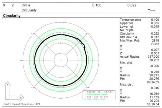
Figure 16.
Circularity results of the machined workpiece under mineral oil conditions.

Figure 17.
Circularity results of the machined workpiece under ionic liquid conditions.
4. Sustainability Assessment
Sustainability assessment of the machining process is vital to meet global demands. This study compared mineral oil and ionic fluid performance in hard turning using a sustainability score derived from a weighted Pugh matrix. The Pugh matrix aids decision-making by evaluating alternatives against weighted criteria, balancing subjective and objective parameters for optimized solutions [38,39]. The weighted Pugh matrix approach evaluates sustainable manufacturing parameters using mathematical scores. Criteria are assigned weights ranging from 10% to 20%, reflecting their importance in decision-making. Weight percentages are converted into integer scores, and alternatives are compared against a baseline. Performance scores are assigned on a scale of −2 (worst), −1 (poor), +1 (good), and 2 (excellent), which are multiplied by the weight scores to calculate weighted scores for each parameter.
In this analysis, the sustainability of mineral oil and ionic fluids was evaluated based on seven key parameters measured after 85 min of machining (Table 2): tool wear, surface quality, cutting power, cutting temperature, cutting noise, carbon emissions, and coolant cost. Lower tool wear is desirable as it increases tool life and reduces replacement costs. Ionic fluid outperforms mineral oil with significantly lower tool wear, receiving a score of +2 compared to +1 for mineral oil. Lower surface roughness indicates better surface quality, critical for part precision. Both fluids meet the industrial standard of 1.6 µm, but ionic fluid demonstrates superior surface quality, scoring +2, while mineral oil scores +1.
Table 2.
Estimated sustainability scores.
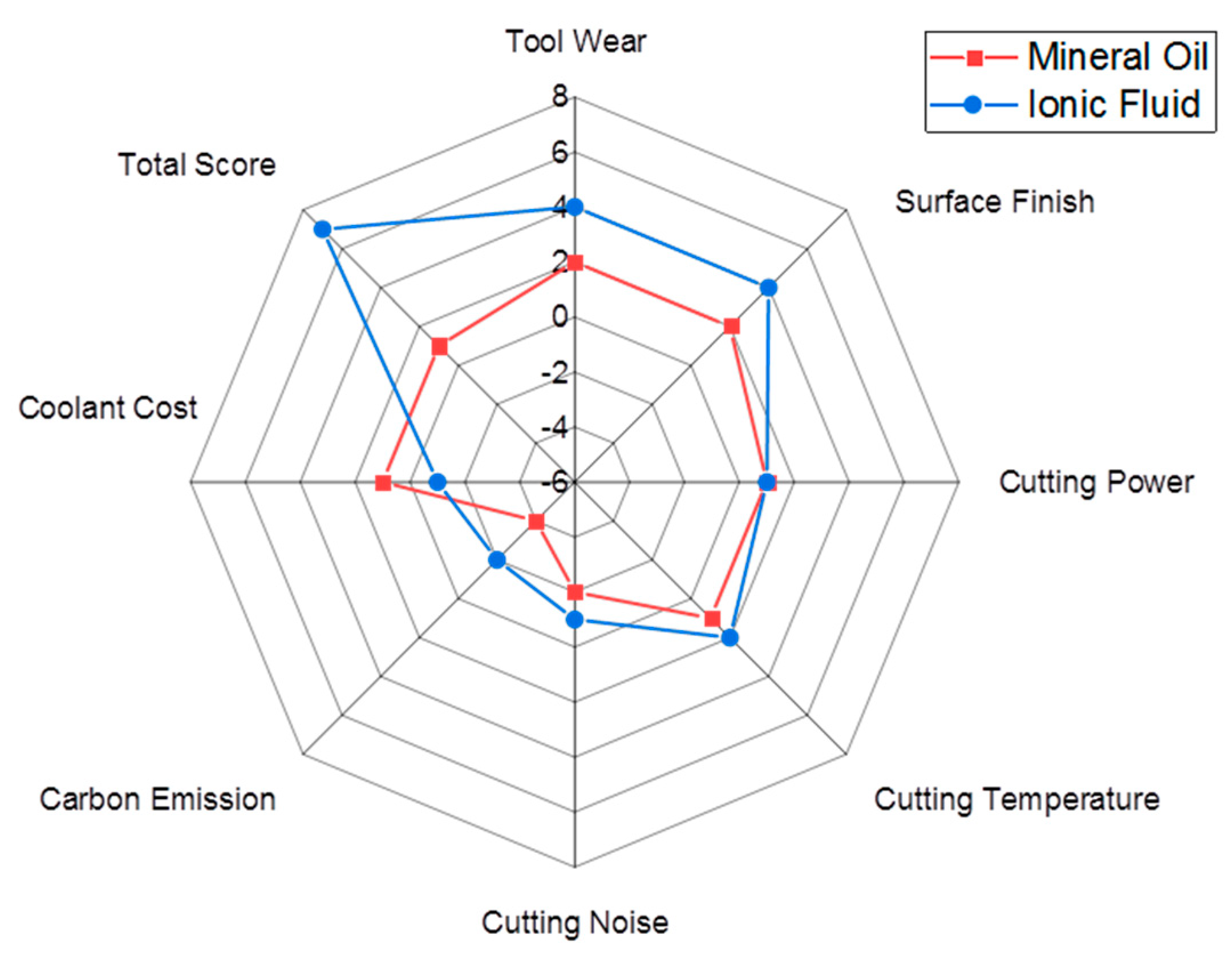
Lowering power consumption reduces energy costs. Ionic fluid slightly outperforms mineral oil in this aspect, but both receive a score of +1 due to the marginal difference. Lower cutting temperature improves tool life and surface quality. The ionic fluid shows significantly lower cutting temperatures, scoring +2, while mineral oil scores +1. Lower noise levels contribute to a safer working environment. Ionic fluid produces less noise, scoring −1, while mineral oil is assigned −2. Carbon emissions are critical for sustainability. Ionic fluid produces lower emissions, scoring −1, compared to −2 for mineral oil. Lower coolant costs enhance cost efficiency; mineral oil scores +1 for its slightly lower cost, while ionic fluid scores −1. Ionic fluid outperforms mineral oil in key areas, achieving a total weight score of +7, compared to +1 for mineral oil. The sustainability comparison is graphically represented using the Kiviat radar plot shown in Figure 18. The scores indicate that the ionic fluid is a more favorable sustainable cooling approach for hard turning.

Figure 18.
Kiviat radar plot illustrating the sustainability scores.
5. Conclusions
In this study, a comparative evaluation of the performance of mineral oil and ionic Taguchi-based cutting fluids in hard turning was conducted. The following major observations were made:
- The tool life under ionic fluid was found to be approximately 103 min, which is 28.75% higher than that of mineral oil (80 min). Abrasion and adhesion were identified as the dominant wear mechanisms leading to tool failure;
- The surface roughness, power consumption, cutting temperature, and carbon emissions under ionic fluid conditions were relatively lower compared to mineral oil, attributed to the better shearing ability of material, reduced tool wear, and extended tool life;
- Cutting noise emission improved with machining time and remained below 85 dB, making it safer for operators in terms of hearing health;
- A significant improvement in circularity error reduction was observed under ionic fluid conditions, with the error being 267% lower than that with mineral oil;
- The weighted Pugh matrix approach gave a higher sustainability score to ionic fluid (+7) compared to mineral oil (+1), making ionic fluid the more sustainable cooling option for hard turning.
Author Contributions
Abstract, R.K.; Introduction, R.M., R.K. and D.D.; Implementation methodology, R.M., R.K., A.P. and D.D.; Experimentation, R.M. and A.P.; Results and Discussion, A.K.S. and R.K.; Writing–review and editing, A.K.S. and R.K.; Supervision, R.K. and A.P.; Sustainability analysis, A.P. and R.K. All authors have read and agreed to the published version of the manuscript.
Funding
This research has no financial support.
Institutional Review Board Statement
Not applicable.
Data Availability Statement
Data are contained within the article.
Acknowledgments
The authors expressed their thanks to KIIT-DU and IIT (ISM) Dhanbad for providing their research facilities to accomplish this novel work.
Conflicts of Interest
The authors declared no conflicts of interest.
References
- Chinchanikar, S.; Choudhury, S.K. Machining of hardened steel—Experimental investigations, performance modelling and cooling techniques: A review. Int. J. Mach. Tools Manuf. 2015, 89, 95–109. [Google Scholar] [CrossRef]
- Davim, J.P. Machining of Hard Materials; Springer: London, UK, 2011. [Google Scholar]
- Craig, M.; Raval, J.; Tai, B.; Patterson, A.; Hung, W. Effect of Channel Roughness on Micro-Droplet Distribution in Internal Minimum Quantity Lubrication. Dynamics 2022, 2, 336–355. [Google Scholar] [CrossRef]
- Paul, I.D.; Bhole, G.P.; Chaudhari, J.R. A Review on Green Manufacturing: It’s Important, Meth-odology and Its Application. Procedia Mater. Sci. 2014, 6, 1644–1649. [Google Scholar] [CrossRef]
- Leppert, T. Surface layer properties of AISI 316L steel when turning under dry and with minimum quantity lubrication conditions. Proc. Inst. Mech. Eng. B J. Eng. Manuf. 2012, 226, 617–631. [Google Scholar] [CrossRef]
- Zhang, S.; Li, J.F.; Wang, Y.W. Tool life and cutting forces in end milling Inconel 718 under dry and minimum quantity cooling lubrication cutting conditions. J. Clean. Prod. 2012, 32, 81–87. [Google Scholar] [CrossRef]
- Bhowmick, S.; Alpas, A.T. The role of diamond-like carbon coated drills on minimum quantity lubrication drilling of magnesium alloys. Surf. Coat. Technol. 2011, 205, 5302–5311. [Google Scholar] [CrossRef]
- Mallick, R.; Kumar, R.; Panda, A.; Sahoo, A.K. Hard Turning Performance Investigation of AISI D2 Steel under a Dual Nozzle MQL Environment. Lubricants 2023, 1, 16. [Google Scholar] [CrossRef]
- Cai, M.; Yu, Q.; Liu, W.; Zhou, F. Ionic liquid lubricants: When chemistry meets tribology. Chem. Soc. Rev. 2020, 49, 7753–7818. [Google Scholar] [PubMed]
- Sultana, M.N.; Dhar, N.R.; Zaman, P.B. A review on different cooling/lubrication techniques in metal cutting. J. Appl. Mech. 2019, 7, 71–87. [Google Scholar] [CrossRef]
- Pereira, O.; Martín-Alfonso, J.E.; Rodríguez, A.; Calleja, A.; Fernández-Valdivielso, A.; De Lacalle, L.L. Sustainability analysis of lubricant oils for minimum quantity lubrication based on their tribo-rheological performance. J. Clean. Prod. 2017, 164, 1419–1429. [Google Scholar]
- Pereira, O.; Rodríguez, A.; Fernández-Valdivielso, A.; Barreiro, J.; Fernández-Abia, A.I.; López-De-Lacalle, L.N. Cryogenic hard turning of ASP23 steel using carbon dioxide. Procedia Eng. 2015, 132, 486–491. [Google Scholar] [CrossRef]
- Pereira, O.; Rodríguez, A.; Barreiro, J.; Fernández-Abia, A.I.; López-De-Lacalle, L.N. Nozzle design for combined use of MQL and cryogenic gas in machining. Int. J. Precis. Eng. Manuf.-Green Technol. 2017, 4, 87–95. [Google Scholar]
- Fernández-Abia, A.I.; Barreiro, J.; López de Lacalle, L.N.; Martínez-Pellitero, S. Behavior of austenitic stainless steels at high speed turning using specific force coefficients. Int. J. Adv. Manuf. Technol. 2012, 62, 505–515. [Google Scholar]
- Jiménez, A.E.; Bermúdez, M.D.; Iglesias, P.; Carrión, F.J.; Martínez-Nicolás, G. 1-N-alkyl-3-methylimidazolium ionic liquids as neat lubricants and lubricant additives in steel–aluminium contacts. Wear 2006, 260, 766–782. [Google Scholar]
- Amiril, S.S.; Rahim, E.A.; Syahrullail, S. A review on ionic liquids as sustainable lubricants in manufacturing and engineering: Recent research, performance, and applications. J. Clean. Prod. 2017, 168, 1571–1589. [Google Scholar] [CrossRef]
- Bambam, A.K.; Gajrani, K.K. In pursuit of sustainability in machining titanium alloys using phosphonium-based halogen-free ionic liquids as potential metalworking fluid additives. Trib. Int. 2024, 199, 109995. [Google Scholar]
- Goindi, G.S.; Chavan, S.N.; Mandal, D.; Sarkar, P.; Jayal, A.D. Investigation of ionic liquids as novel metalworking fluids during minimum quantity lubrication machining of a plain carbon steel. Procedia CIRP 2015, 26, 341–345. [Google Scholar]
- Sabarinath, S.; Rajendrakumar, P.K.; Nair, P.K. Evaluation of tribological properties of sesame oil as biolubricant with SiO2 nanoparticles and imidazolium-based ionic liquid as hybrid additives. Proc. Inst. Mech. Eng. Part J IME J. Eng. Tribol 2019, 233, 1306–1317. [Google Scholar]
- Babu, M.N.; Anandan, V.; Babu, M.D. Performance of ionic liquid as a lubricant in turning Inconel 825 via minimum quantity lubrication method. J. Manuf. Process. 2021, 64, 793–804. [Google Scholar]
- Sah, N.K.; Singh, R.; Sharma, V. Experimental investigations into thermophysical, wettability and tribological characteristics of ionic liquid based metal cutting fluids. J. Manuf. Process. 2021, 65, 190–205. [Google Scholar]
- Davis, B.; Schueller, J.K.; Huang, Y. Study of ionic liquid as effective additive for minimum quantity lubrication during titanium machining. Manuf. Lett. 2015, 5, 1–6. [Google Scholar]
- Srinivas, M.S.; Panneer, R.; Suvin, P.S.; Kailas, S.V. Synthesis and testing of novel neem oil-based cutting fluid with ionic liquid additives. In Industry 4.0 and Advanced Manufacturing: Proceedings of I-4AM; Springer: Singapore, 2021; pp. 311–322. [Google Scholar]
- Dharaskar, S.A.; Varma, M.N.; Shende, D.Z.; Yoo, C.K.; Wasewar, K.L. Synthesis, characterization and application of 1-butyl-3 methylimidazolium chloride as green material for extractive desulfurization of liquid fuel. Sci. World J. 2013, 1, 395274. [Google Scholar]
- Jadam, T.; Datta, T.S.; Masanta, M. Studies on Chip Morphology and Modes of Tool Wear During Machining of Ti-6Al-4V Using Uncoated Carbide Tool: Application of Multi-Walled Carbon Nanotubes Added Rice Bran Oil as Nanocutting Fluid. Mach. Sci. Technol. 2021, 25, 237–287. [Google Scholar]
- Huda, Z. Machining Processes and Machines: Fundamentals, Analysis, and Calculations, 1st ed.; CRC Press: Boca Raton, FL, USA, 2020. [Google Scholar]
- Bilga, P.S.; Singh, S.; Kumar, R. Optimization of energy consumption response parameters for turning operation using Taguchi method. J. Clean. Prod. 2016, 137, 1406–1417. [Google Scholar]
- Avilés, M.D.; Sánchez, C.; Pamies, R.; Sanes, J.; Bermúdez, M.D. Ionic Liquid Crystals in Tribology. Lubricants 2019, 7, 72. [Google Scholar] [CrossRef]
- Donato, M.T.; Colaço, R.; Branco, L.C.; Saramago, B.; Canongia Lopes, J.N.; Shimizu, K.; Freitas, A.A.D. Molecular Interactions between Ionic Liquid Lubricants and Silica Surfaces: An MD Simulation Study. J. Phys. Chem. B 2024, 128, 2559–2568. [Google Scholar] [PubMed]
- Syahir, A.Z.; Zulkifli, N.W.M.; Masjuki, H.H. Tribological Improvement Using Ionic Liquids as Additive in Synthetic and Bio-Based Lubricant for Steel-Steel Contact. Tribol. Trans. 2020, 63, 235–250. [Google Scholar]
- Şahinoğlu, A.; Rafighi, M.; Kumar, R. An investigation on cutting sound effect on power consumption and surface roughness in CBN tool-assisted hard turning. Proc. Inst. Mech. Eng. Part E J. Process Mech. Eng. 2022, 236, 1096–1108. [Google Scholar]
- Mallick, R.; Kumar, R.; Panda, A.; Sahoo, A.K.; Sahu, R.; Swain, J. Assessing hard-turning performance improvement using ionic liquid-infused cutting fluids: Tribological benefits, tool life assessment, and sustainable machining. Proc. Inst. Mech. Eng. Part C J. Mech. Eng. Sci. 2025. [Google Scholar] [CrossRef]
- Lamikiz, A.; López de Lacalle, L.N.; Ocerin, O.; Díez, D.; Maidagan, E. The Denavit and Hartenberg approach applied to evaluate the consequences in the tool tip position of geometrical errors in five-axis milling centres. Int. J. Mach. Tools Manuf. 2008, 37, 122–139. [Google Scholar]
- Madhu, P.; Rao, A.S. Interactive approach in improving rigidity of lathe structure. Int. J. Interact. Des. Manuf. 2021, 15, 35–45. [Google Scholar]
- Ghorbani, S.; Kopilov, V.V.; Polushin, N.I.; Rogov, V.A. Experimental and analytical research on relationship between tool life and vibration in cutting process. Arch. Civ. Mech. Eng. 2018, 18, 844–862. [Google Scholar] [CrossRef]
- Tunc, L.T.; Budak, E. Effect of cutting conditions and tool geometry on process damping in machining. Int. J. Mach. Tools Manuf. 2012, 6, 10–19. [Google Scholar]
- Díaz-Tena, E.; Ugalde, U.; López de Lacalle, L.N.; De la Iglesia, A.; Calleja, A.; Campa, F.J. Propagation of assembly errors in multitasking machines by the homogenous matrix method. Int. J. Adv. Manuf. Technol. 2013, 68, 149–164. [Google Scholar] [CrossRef]
- Ross, N.S.; Rai, R.; Ananth, M.B.J. Carbon emissions and overall sustainability assessment in eco-friendly machining of Monel-400 alloy. Sustain. Mater. Technol. 2023, 37, e00675. [Google Scholar]
- Roy, S.; Kumar, R.; Panda, A.; Sahoo, A.K.; Rafighi, M.; Das, D. A Comparative Performance Investigation of Single- and Double-Nozzle Pulse Mode Minimum Quantity Lubrication Systems in Turning Super-Duplex Steel Using a Weighted Pugh Matrix Sustainable Approach. Sustainability 2023, 15, 15160. [Google Scholar] [CrossRef]


Disclaimer/Publisher’s Note: The statements, opinions and data contained in all publications are solely those of the individual author(s) and contributor(s) and not of MDPI and/or the editor(s). MDPI and/or the editor(s) disclaim responsibility for any injury to people or property resulting from any ideas, methods, instructions or products referred to in the content. |
© 2025 by the authors. Licensee MDPI, Basel, Switzerland. This article is an open access article distributed under the terms and conditions of the Creative Commons Attribution (CC BY) license (https://creativecommons.org/licenses/by/4.0/).