Abstract
To enhance the operational stability and service life of tapered roller bearings (TRBs), this study investigates the application of surface texturing technology using laser marking to fabricate micro-dimples with controlled diameters and distributions on the TRB outer ring. An orthogonal experimental design was implemented to systematically evaluate the effects of three key dimple parameters—diameter, depth, and angular distribution—on the tribological performance under starved lubrication. The results demonstrate that the textured surfaces significantly improve friction-reducing performance and wear resistance. Optimal dimple parameters (diameter: 200 μm, depth: 10 μm, angular interval: 0.9°) were identified, achieving a 43.6% reduction in the average coefficient of friction (COF) and a 75.7% decrease in wear loss compared to smooth bearings. These findings would offer a practical approach to enhancing the durability and operational reliability of TRBs in industrial applications.
1. Introduction
Tapered roller bearings (TRBs) are widely recognized for their ability to support both axial and radial loads, making them indispensable in industries such as the automotive, machine tools, and heavy machinery industries [1,2]. With the advancement of industrial transmission systems toward higher speeds and heavier loads, TRBs encounter critical technical challenges, including excessive energy consumption due to friction, reduced service life caused by severe wear, and difficulties in controlling vibration and noise [3,4,5]. These challenges not only lower the energy conversion efficiency of transmission systems, but also compromise the dynamic stability and long-term reliability of bearing operation [6,7]. Consequently, enhancing the tribological performance of TRBs and mitigating wear have become essential for improving their service life and efficiency [8,9].
Since the emergence of surface texturing technology in the 1960s, extensive research has demonstrated that surface textures can store lubricants, decrease the actual contact area, and trap wear debris, thereby improving lubrication conditions [10,11,12,13]. In addition, studies have shown that the roughness within and outside of the laser texture is different [14]. The combination of surface textures and different surface roughness values can enhance the lubrication performance [15,16,17]. By strategically designing the shape and distribution of dimples, tribological performance can be significantly enhanced, wear progression can be slowed, and the service life of TRBs can be effectively prolonged.
Sun et al. [18] investigated the effect of initial deflection angles on the tribological performance of dimple-textured gray cast iron surfaces. Their experiments revealed that, compared to smooth surfaces, the textured surfaces generated distinct high-temperature zones between adjacent dimple configurations. When the initial deflection angle was 45°, both the coefficient of friction (COF) and wear loss reached their lowest values, demonstrating superior wear resistance. Lin et al. [19] employed picosecond laser technology to fabricate dimple textures on WC-Ni composite coatings and conducted an in-depth analysis of their impact on tribological performance. The results indicated that circular dimples effectively retained lubricants and trapped wear debris, leading to a significant reduction in the COF and wear loss. Yan et al. [20] utilized selective laser melting and high-temperature melt infiltration techniques to fabricate 60NiTi biomimetic surface textures with self-lubricating composite materials. Their study found that samples with moderate dimple density exhibited the best performance in reducing wear loss and enhancing lubrication.
The application of surface texturing in critical regions of rolling bearings, such as raceways and rolling elements, has shown great potential in mitigating edge stress concentration, delaying fatigue spalling, and enhancing fluid dynamic lubrication under mixed or boundary lubrication conditions [21,22,23,24]. Consequently, numerous researchers have conducted extensive studies in this field. Sun et al. [25] investigated the effects of dimple textures on the frictional and wear behavior of rolling bearings under dry friction conditions. Their study focused on how variations in dimple diameter, depth, and circumferential spacing influence bearing performance. The results indicated that, in dry friction environments, dimple textures significantly improve the friction and wear properties of bearings, and an optimized texture design can effectively reduce frictional forces and wear levels. Chen et al. [26] proposed multiple surface texture patterns and examined their tribological performance when applied to different locations on bearings. Their findings revealed that, under starved lubrication conditions, an appropriate dimple distribution can effectively reduce friction and wear, thereby enhancing bearing durability. Zhao et al. [27,28,29] analyzed the influence of dimple textures on both the tribological and dynamic performance of rolling bearings operating under lubricant contamination conditions. Their results demonstrated that dimple textures not only improve tribological performance but also suppress high-frequency vibration energy within bearings. Additionally, the diameter and coverage area of the dimples play a crucial role in their ability to trap contaminants. Wu et al. [30,31] developed an innovative self-lubricating biomimetic composite texture for thrust ball bearings. Experimental results showed that, compared to normal bearings, the self-lubricating biomimetic textured bearings exhibited superior vibration suppression and tribological performance. The improved lubrication efficiency of the textured bearings was attributed to the enhanced lubricant retention capability of the surface textures.
Cylindrical and spherical rolling bearings, such as ball bearings and cylindrical roller bearings, have achieved significant advancements in surface texturing [32,33,34,35,36]. However, the application of surface texture in TRBs remains underdeveloped, and related research is relatively limited. Gimeno et al. [37] explored the effects of laser texturing technology on the tribological performance of TRBs, considering multiple factors such as fatigue life, friction, and wear. They initially analyzed the influence of dimple diameter, height, and density on sample surfaces, and subsequently applied the optimal texture parameters to the entire bearing system. Their study confirmed that surface texturing offers notable advantages for rolling surfaces under lubrication conditions. Wang et al. [38,39] employed laser marking technology to generate dimple textures on bearing raceways and investigated how different laser texturing parameters—including dimple diameter, depth, and area density—affect the friction and vibration characteristics of TRBs under varying lubrication conditions. The findings demonstrated that dimple textures significantly reduced friction, highlighting their potential for enhancing the tribological performance of TRBs.
However, despite the significant impact of dimpled textures on enhancing the tribological performance of TRBs, research on the precise parameter design of these textures—particularly the effects of dimple diameter, depth, and distribution angle on friction and wear performance—remains relatively scarce.
Therefore, building upon the team’s previous work [13,18,25,26,38,39], this study employs an orthogonal experimental approach in combination with laser marking technology to design various dimpled textures on the outer ring surface of TRBs. A systematic investigation is conducted to evaluate the influence of texture parameters on the tribological performance of the bearings, and the optimal dimple parameter combination is experimentally validated. The findings of this study provide valuable insights for optimizing the performance of mechanical components, extending their service life, enhancing reliability, and reducing energy consumption through surface texturing.
2. Materials and Methods
2.1. Preparation of Dimpled Textures
A 30206 tapered roller bearing (HRB, Harbin, China) was selected for this study. The bearing comprises outer ring, cage, 17 rollers, and inner ring, with the cage, rollers, and inner ring forming an integrated unit, as illustrated in Figure 1a,b. Before the surface texture treatment of the bearing, a standardized pretreatment process needs to be completed, including removing the anti-rust grease attached to the packaging and storage, ultrasonic cleaning with acetone solution for 10 min, and hot air drying to ensure that the surface cleanliness meets the subsequent processing requirements.
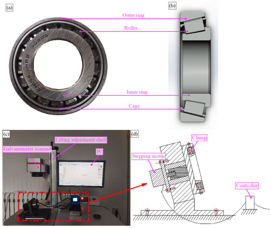
Figure 1.
(a) the 30206 TRB; (b) cross-section view of the TRB; (c) laser marking machine and fixture; (d) fixture design diagram.
The surface of the outer raceway of the bearing was textured using a PL100-30W laser marking machine (Sepbase, Shenyang, China). Marking parameter settings were as follows: pulse frequency 80 kHz, scanning speed 200~300 mm/s, laser power 1~3 W, and wavelength 1064 nm. Combined with the servo motor motion controller, the vertical laser marking with a fixed angle on the inner surface of the outer raceway was realized. The outer ring of the bearing was installed on the fixture, and the laser marking was started after entering the marking parameters. First, a position was marked on the surface of the raceway, and then the servo motor rotated to the next position according to the set angle and continued to mark. The process was repeated until the entire surface marker was completed. The fixture and laser marking machine setups are shown in Figure 1c,d.
After laser texture treatment, the outer ring surface was polished with 1200#, 1500#, and 2000# sandpaper in turn to remove the molten edge formed during the laser marking process. Finally, the outer ring of the bearing was ultrasonically cleaned in acetone for 15 min to remove residual debris and dried with a hot air blower. The arithmetic mean height of the surface roughness of the outer raceway of the bearing is within the range of 6 ± 0.5 μm.
2.2. Orthogonal Experimental Design
In order to study the influence of dimple texture parameters (diameter, depth, and distribution angle) on the friction performance of the outer raceway of TRBs, the orthogonal test design of three factors and three levels was adopted, and based on Wang’s research [29], the representative parameter combination was selected for the test. The L9 (34) orthogonal table was used in the experimental design, and the D column was used as the error column for variance analysis. The orthogonal table used is listed in Table 1. All pits are arranged in a 300 μm spacing, with 40 pits per row, as shown in Figure 2.

Table 1.
L9 (34) Orthogonal experimental design.
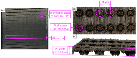
Figure 2.
(a) pits on the outer ring; (b) surface morphology of the pits; (c) the 3D topography of the pits is enlarged by 1000% in the Z-direction.
2.3. Friction and Wear Test
Friction and wear tests were performed using a vertical multifunctional friction and wear testing machine (see Figure 3a). Based on preliminary research, the test parameters were set as follows: spindle speed of 250 rpm, axial load of 2600 N, and a duration of 37,000 s. During the experiment, the temperature was maintained at room temperature, which was 25 ± 5 °C. Before the experiment, the cleaned inner and outer rings were weighed three times using an electronic balance (see Figure 3b). Subsequently, 6 mg of lubricant (kinematic viscosity 14.45 mm2/s, density 0.8678 kg/L, 30 °C) was evenly applied to the outer raceway of the bearing. The outer ring was assembled with an inner ring/rolling element/cage into a complete bearing and rotated 10 times. No lubricant was added during the test.
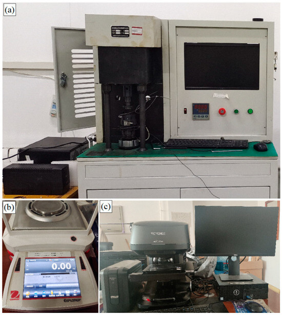
Figure 3.
(a) wear test rig; (b) electronic balance; (c) the 3D surface profilometer.
The testing machine adopts a numerical control hydraulic servo control system to achieve precise load application. The specific load application process is as follows: after the bearing is installed, first, the initial pressurization rate of the lower fixture is set to 100 to make the bearing move upward rapidly. When the bearing is about to make contact with the upper fixture, the pressurization rate is immediately reduced to 20 to ensure smooth contact. After the initial contact is established, the basic rotational speed of the bearing is set at 50 rpm. When the system detects that the actual load reaches 500 N, the pressurization rate is further adjusted to 2, and simultaneously, the rotational speed is slowly increased to the target value of 250 rpm. When the feedback value of the load sensor reaches 2000 N, the loading continues at a micro-feed rate of 0.2. Finally, the test load is stably controlled within the range of 2600 ± 100 N until the end of the test. This progressive loading strategy based on multi-stage variable parameters effectively avoids the stress impact caused by traditional step loading and ensures the accuracy of test data.
After the test, the bearing was cleaned in an acetone ultrasonic cleaner for 15 min, and the mass of the inner and outer rings was measured by an electronic balance (EX225D, Ohaus, Changzhou, China, 0.01 mg readability). The wear loss was calculated by the average mass difference before and after the test. As shown in Figure 3c, The worn surface was characterized by a 3D surface profilometer (VK-X 1050, Keynes, Osaka, Japan). The test process is shown in Figure 4.
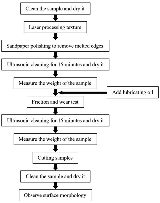
Figure 4.
Schematic diagram of the test process.
To reduce system and random errors, each group of pit parameter tests was repeated three times, and the average value of the friction curve and wear loss was taken. All tests were carried out strictly according to the same procedure to ensure that the test conditions were consistent.
3. Results and Analysis
3.1. Tribological Performance
Figure 5 shows the influence of different pit parameter combinations on the COF curve of TRBs under starved lubrication conditions, i.e., without any oil supplied during the whole process, and compares it with the non-textured bearings (G00). The label ‘G01-200-5-0.9’ represents ‘group number-diameter-depth-distribution angle’. The friction curve analysis shows that the running state of the bearing can be divided into two stages: the running–in period and the stable period. The duration of the running–in period state ranges from 0 to 10,800 s. During this period, the COF of each group exhibits significant fluctuating characteristics. The reason for this lies in the fact that the surface of a new bearing has randomly distributed micro-asperities. The actual contact area is relatively small and concentrated at the tips of these micro-asperities, resulting in a relatively large COF. During the initial operation of the bearing, with the relative motion, the micro-asperities continuously collide, extrude, and deform with each other. This leads to continuous changes in the magnitude of the frictional force, thus causing fluctuations in the frictional force. In the later stage of the running–in period state, these micro-asperities are gradually worn away. As a result, the contact area increases, the contact pressure distribution becomes more uniform, and the contact surface gradually becomes smoother. Consequently, the COF shows a decreasing trend. Moreover, as time progresses further, the COF gradually stabilizes, indicating that the bearing has entered the stable period.
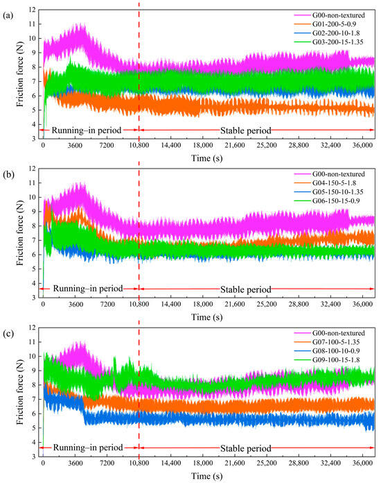
Figure 5.
COF curves of G00 and G01-G09 under starved lubrication, grouped as (a) G01-G03, (b) G04-G06, and (c) G07-G09.
Compared with the non-textured group (G00), except for the fact that the COF of G09 was slightly higher in the stable period, the other eight groups were lower, indicating that the pit texture can reduce the bearing COF. In addition, there are differences in the range of friction fluctuation between different experimental groups during the stable period. The COF of the group with a smaller fluctuation is more stable, the wear is lighter, the lubrication is better, and the running state is more stable. On the contrary, the group with large fluctuations indicates increased wear, insufficient lubrication, and unstable operation. This fluctuation may be affected by texture parameters (diameter, depth, and angle).
Furthermore, the textured bearings exhibited a positive effect on reducing the running–in period, facilitating a quicker transition to the stable period, and extending the bearing’s service life. As shown in Figure 5, the running–in period for the non-textured bearings lasted approximately 10,800 s, whereas the presence of pit textures effectively reduced the contact area between the friction pairs. In addition, the pit can capture wear debris, reduce its secondary damage to the friction surface, make the contact surface smoother, and accelerate the bearing into the stable period. In the later stage of stable period, the COF of non-textured bearings increase due to insufficient lubrication and wear debris accumulation. In contrast, only the COF of the G04 and G09 groups increased significantly, indicating that the textured surface extended the lubrication time through the ‘secondary lubrication‘ mechanism and reduced the wear during the stable period, thereby increasing the bearing’s service life.
The average COF and wear loss of all test groups are summarized in Figure 6. In order to reduce the influence of initial operation instability, the average COF calculation is based on the 3600~37,000 s period. From the point of view of wear loss, the wear loss of the outer ring accounts for 73~83% of the total wear loss, which is relatively large. In order to further analyze the effect of pit texture on wear loss, the total wear loss was evaluated. The total wear loss of pit-textured bearings is 3.36~13.14 mg, of which eight groups are lower than the non-textured group (13.07 mg), and the lowest is 3.36 mg, which is reduced by 74.29%. This shows that the reasonable design of the pit texture can significantly reduce wear loss. However, the wear loss of the G09 group reached 13.14 mg, which was higher than that of the non-textured group, indicating that improper combination of texture parameters may aggravate wear loss. Therefore, in order to achieve the best anti-friction effect, the texture parameters need to be further optimized.
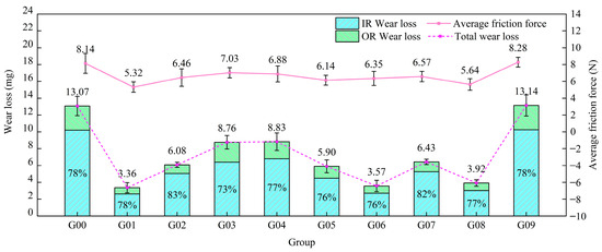
Figure 6.
Average COF and wear loss of G00-G09 under starved lubrication.
3.2. Analysis of Average COF
Analysis of COF Range
As shown in Table 2, based on the orthogonal experimental design, the range analysis method was used to determine the optimal texture parameter combination that minimizes the friction. In the table, Kin (n = 1, 2, 3) represents the sum of the indicators of each factor at the same level, and kin (n = 1, 2, 3) is the corresponding average. In this study, three levels were set for each factor, and the calculation formula was kin = Kin/3.
Table 2.
Analysis of average COF for pit-textured TRBs.
For the pit diameter, the results show that ki3 > ki2 > ki1, indicating that the COF decreases with an increase in the pit diameter. For pit depth, the average COF ki2 of level 2 (depth: 10 μm) is 6.08, which is slightly lower than that of level 1 (ki1 = 6.26), but significantly lower than that of level 3 (ki3 = 7.22). This phenomenon may be due to the fact that the lubricant is trapped in the pit when the depth of the pit is large, which hinders the formation of a uniform lubricating film on the contact surface. This trap effect reduces the distribution of the lubricant between the contact surfaces, which in turn hinders the pits from effectively providing secondary lubrication, resulting in deterioration of the lubrication conditions. With the thinning of the lubricating film, the COF increases, resulting in higher friction, which may lead to fretting wear. In addition, when the pit distribution angle is 0.9°, 1.35°, and 1.8°, the average COF is 5.77, 6.58, and 7.21, respectively, indicating that the COF increases with an increase in the pit distribution angle.
The range analysis of an orthogonal experiment is a simple and effective method for analyzing the results of orthogonal experiments. It can help us determine the influence degree of each factor on the experimental index and identify the optimal combination of factor levels. Based on the magnitudes of the average values of the test indicators under different levels of each factor, we can select the combination of factor levels that enables the test indicators to reach the optimal state. For TRBs, lower COF means less surface wear and better lubrication performance. Based on the test results, the optimal texture parameter combination of TRBs is A1B2C1, that is, the pit diameter is 200 μm, the depth is 10 μm, and the distribution angle is 0.9°.
The R value (range) in Table 2 is calculated by the formula R = max{kin} − min{kin}, where the R value reflects the degree of influence of each factor on the average friction. The larger the range, the more significant the influence of this factor on friction. The range of the error sequence (D) is the smallest, indicating that the pit spacing, diameter, and depth have a certain influence on the COF. The R value of the pit distribution angle (factor C) is the largest, which is 1.44, indicating that it has the greatest influence on the COF. The second is the pit depth (factor B), and its R value of 1.14, which also has a great influence on the COF. The R value of the pit diameter (factor A) is the smallest, which is 0.56, indicating that it has little effect on the COF.
The orthogonal test results show that the pit distribution angle has the greatest influence on the average COF, followed by the pit depth, and that the pit diameter has less influence. In addition, the optimal combination of pit parameters is a pit diameter of 200 μm, depth of 10 μm, and distribution angle of 0.9°. This combination helps to improve the wear resistance and overall lubrication performance of the bearing.
4. Verification Test
4.1. COF and Wear Loss
In order to verify the performance of the optimal texture combination obtained by orthogonal experiments in practical applications, we performed laser processing on the optimized A1B2C1D2 samples (diameter 200 μm, depth 10 μm, and distribution angle 0.9°), labeled as the G10 group. Subsequently, the test of the textured bearing was carried out under the same conditions, and the results were compared with the non-textured TRB (G00) and the groups with the smallest and largest friction in the orthogonal experiment (G01 and G09). The variation curves of COF with time in each group is shown in Figure 7.
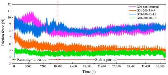
Figure 7.
COF curves of G00, G01, G09, and G10 groups.
It can be seen from the friction curve in Figure 7 that under the same test of G00, G01, G09, and G10 conditions, the optimized experimental group (G10) passed the runing-in period quickly and entered the stable stage. In the stable stage, the friction of each group tends to be stable. The COF of the G00 group remained at a high level (8~10 N), while the pit texture group showed significantly lower COF. In contrast, the COF of the G10 group is the lowest (3~5 N), and the fluctuation is the smallest. This indicates that compared with the G01 group, the texture parameters of G10 are more effective at reducing friction and maintaining stable lubrication. The enhanced stability and reduced friction of the G10 group can be attributed to the optimization of the pit depth, which provides better lubrication storage and collects more wear debris, thereby significantly reducing the COF.
Figure 8 shows the wear loss and average COF of G00, G01, G09, and G10. The smooth surface group (G00) showed a higher wear loss (13.07 mg), while the pit texture groups (G01 and G10) were significantly better than the smooth group. The optimized G10 group showed the lowest wear loss, with only 3.18 mg. This result further proves that the optimized G10 pit texture has a significant advantage in reducing wear and shows better tribological properties.
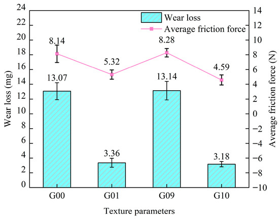
Figure 8.
Average COF and total wear loss of G00, G01, G09, and G10 groups.
The average COF of the G10 group was significantly reduced to 4.59 N, which was 13.72% lower than that of the G01 group (5.32 N), with the lowest COF in the orthogonal test. This shows that the texture parameters (G10) obtained by orthogonal experiments are indeed the optimal combination to achieve the lowest friction.
Compared with the G01 group, the G10 group has a more reasonable pit depth to ensure the uniform distribution of the lubricating oil on the contact surface. In addition, the pits effectively capture the wear debris and reduce the occurrence of third-body wear. The optimized combination of texture parameters in G10 can better achieve the secondary lubrication effect, significantly reducing the COF and wear loss.
4.2. Surface Morphology Analysis
The wear morphologies of the rollers and outer rings of G00, G09, G01, and G10 samples after ultrasonic cleaning are shown in Figure 9. The surface of the roller and outer ring of the G00 group showed obvious wear marks during the friction process. Due to the lack of any texture structure, the lubricating oil cannot be effectively stored and distributed, resulting in high contact stress on the contact surface, resulting in deep and wide parallel scratches. These scratches are mainly due to insufficient lubrication and adhesive wear caused by direct contact between metal and metal. In addition, dark brown discoloration appeared in the right area of the roller and the outer ring, indicating that high temperature ablation occurred.
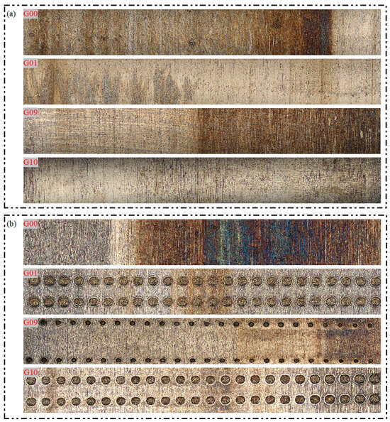
Figure 9.
Surface morphology of the G00, G01, G09, and G10 groups: (a) roller surface; (b) inner surface of the outer ring.
Compared with the G00 group, the G09 group has a pit with a diameter of 100 μm and a depth of 15 μm. However, due to the sparse distribution of the pits, the distribution of the lubricating oil on the contact surface between the roller and the outer ring is uneven, resulting in insufficient lubrication in the area between the pits. Local stress was concentrated, especially in these areas, resulting in significant adhesive wear. High temperature ablation occurred, and the surface color of the high stress area deepened. Although the pit design of the G09 sample improves the lubrication to a certain extent, the overall wear control effect is not significantly better than that of the G00 group due to the insufficient optimization of the pit depth and distribution.
Compared with G00 and G09, G01 shows better wear resistance on the surface of roller and outer ring. The morphology shows that the depth and number of scratches are significantly reduced, and the adhesive wear is effectively controlled. The pit design improves the storage and release of lubricating oil and reduces the risk of high temperature ablation. However, although the lubrication performance of G01 is significantly improved, some fatigue pitting corrosion still occurs in the high stress area, which is manifested as a small range of spalling and pits, indicating that the material will still undergo fatigue damage under cyclic stress.
Under the optimized pit parameters, the G10 sample showed the best wear resistance. The surface morphology shows shallow and evenly distributed scratches, and there is almost no sign of high temperature ablation. The optimized pit parameters ensure that the lubricating oil can effectively cover the high stress area and prevent the oxidation reaction caused by friction heat accumulation. In addition, no obvious fatigue pitting was observed, indicating that G10 achieved the optimal stress distribution and lubrication effect, which effectively inhibited the material fatigue under cyclic stress [11,12,40].
Based on the above analysis, the performance of G10 is obviously better than other groups. By further optimizing the pit parameters, G10 significantly improves the continuity and uniformity of lubrication supply, effectively suppresses high-temperature ablation and fatigue pitting, and achieves the best wear resistance. These results highlight the key role of pit depth, diameter, and distribution density optimization in improving lubrication, reducing adhesive wear and preventing high temperature ablation. The design of the G10 group provides an effective solution to improve the wear resistance of rollers and outer rings under high load friction conditions, and has broad practical application potential.
5. Conclusions
The key conclusions of the study are as follows:
- (1)
- Through the orthogonal test analysis, the R values reflecting the influence of pit diameter, pit depth, and pit distribution angle on the average COF are 0.56, 1.14, and 1.44, respectively. This clearly shows that the influence of the pit distribution angle on the average COF is the most significant, followed by the pit depth, and that the influence of the pit diameter is relatively small. The optimal combination of pit texture parameters is as follows: diameter 200 μm, depth 10 μm, and distribution angle 0.9°.
- (2)
- The dimple texture significantly reduces the COF of the bearing during operation, especially under the condition of insufficient oil lubrication. The optimized texture parameters effectively achieve a 43.6% reduction in COF, accelerate the stable transition of the bearing, and reduce friction wear.
- (3)
- The optimized texture design significantly reduces the wear. Compared with the G00 group, the wear of the optimized bearing in the G10 group is reduced by up to 75.7%. This shows that the surface texture design effectively improves the retention and distribution of the lubricant and reduces wear.
Author Contributions
R.L., Q.M., Q.S., H.W., Y.Y., Y.W. and L.Z. conceived the idea, carried out the experiments, and analyzed the results. R.L. wrote and revised the manuscript. All authors have read and agreed to the published version of the manuscript.
Funding
This research was funded by Natural Science Foundation of Liaoning Province (No. 2023-MS-234), the Scientific Research Fund of Liaoning Provincial Education Department (No. LJKMZ20220800), “Da Biao Li Xiang” project of Shenyang University of Chemical Technology (No. 512000001185), the National Natural Science Foundation of China (No. 52275156), the National Natural Science Foundation of China Young Scientist Fund (No. 52402484) and the University-level doctoral special research start-up fund support project (No. szy2024bs002).
Data Availability Statement
The original data used to support the findings of this study are available from the corresponding author upon request.
Conflicts of Interest
The authors declare no competing interests.
References
- Li, X.B.; Liu, J.; Huang, S.H.; Pan, G. Friction moment calculation method for tapered roller bearings under combined loads. Sci. China-Technol. Sci. 2024, 67, 2565–2578. [Google Scholar] [CrossRef]
- Wang, X.H.; Bian, Q.; Gao, X.H.; Zhao, C.J.; Liu, M.H.; Xie, X.H.; Jiao, B.W. Study on the vibration characteristics of double-row tapered roller bearings for high-speed rail axle box. Ind. Lubr. Tribol. 2024, 76, 678–687. [Google Scholar]
- Ansari, A.K.; Kumar, P. Vibration and acoustics analyses of tapered roller bearing. J. Vib. Eng. Technol. 2023, 12, 2467–2484. [Google Scholar] [CrossRef]
- Wang, A.L.; Wang, J.G. Temperature distribution and scuffing of tapered roller bearing. Chin. J. Mech. Eng. 2024, 27, 1272–1279. [Google Scholar] [CrossRef]
- Liebrecht, J.; Si, X.; Sauer, B.; Schwarze, H. Investigation of drag and churning losses on tapered roller bearings. Stroj. Vestn.—J. Mech. Eng. 2015, 61, 399–408. [Google Scholar]
- Metcalfe, R.G.; Costanzi, R.; Horner, G.; Vance, J. Hydrogen embrittlement of a tapered roller bearing due to lubricant breakdown. Eng. Fail. Anal. 2022, 139, 106436. [Google Scholar] [CrossRef]
- Jain, A.; Singh, A.; Singh, A.P. Effect of tribological parameters on sliding wear and friction coefficient which relates to preload loss in tapered roller bearing. Ind. Lubr. Tribol. 2019, 71, 61–73. [Google Scholar] [CrossRef]
- El-Thalji, I.; Jantunen, E. A descriptive model of wear evolution in rolling bearings. Eng. Fail. Anal. 2014, 45, 204–224. [Google Scholar] [CrossRef]
- Zhou, R.; Li, M.; Liu, H.; Pan, W.; Zhang, R.F.; Liu, Y. Theoretical and experimental study on the evolution of contact load during wear failure of cylindrical roller bearings. Eng. Fail. Anal. 2025, 169, 109218. [Google Scholar]
- Hamilton, D.B.; Walowit, J.A.; Allen, C.M. A theory of lubrication by micro irregularities. J. Basic. Eng. 1966, 88, 177–185. [Google Scholar]
- Costa, H.L.; Hutchings, I.M. Hydrodynamic lubrication of textured steel surfaces under reciprocating sliding conditions. Tribol. Int. 2007, 40, 1227–1238. [Google Scholar] [CrossRef]
- Tang, Z.Q.; Liu, X.J.; Liu, K. Effect of surface texture on the frictional properties of grease lubricated spherical plain bearings under reciprocating swing conditions. Proc. Inst. Mech. Eng. Part J J. Eng. Tribol. 2017, 231, 122–135. [Google Scholar] [CrossRef]
- Long, R.S.; Shang, Q.Y.; Sun, S.N.; Wang, S.W.; Ma, C.; Zhang, J.W.; Marian, M. Influence of Monstera riedrichsthalii bionic textures on the tribological and vibration behavior of rolling bearings. Friction 2025, 13, 9440949. [Google Scholar] [CrossRef]
- Xiang, G.; Yang, T.Y.; Guo, J.; Wang, J.X.; Liu, B.; Chen, S.A. Optimization transient wear and contact performances of water-lubricated bearings under fluid-solid-thermal coupling condition using profile modification. Wear 2022, 502, 204379. [Google Scholar]
- Deng, L.F.; Su, J.; Jin, Z.Y. Effect of composite textured rough surfaces on the lubrication performance of cylindrical roller bearings. Ind. Lubr. Tribol. 2024, 76, 852–863. [Google Scholar] [CrossRef]
- Yin, B.F.; Zhou, H.Q.; Xu, B.; Jia, H.K. The influence of roughness distribution characteristic on the lubrication performance of textured cylinder liners. Ind. Lubr. Tribol. 2019, 71, 486–493. [Google Scholar] [CrossRef]
- Zhang, F.Y.; Yang, J.M.; Shui, H.C.; Dong, C.C. Effect of roughness on sealing performance of oil seals with surface texture. Ind. Lubr. Tribol. 2019, 72, 525–532. [Google Scholar]
- Sun, S.N.; Long, R.S.; Zhang, Y.M.; Li, M.H. The influence of initial deflection angle on the tribological properties of gray cast iron rings with curve distributed pits under dry sliding. Proc. Inst. Mech. Eng. Part. J-J. Eng. Tribol. 2021, 235, 1659–1668. [Google Scholar]
- Lin, G.P.; Cai, Z.B.; Lu, B.W.; Gu, L.; Wang, Y.L.; Yan, X.C.; Qiu, H.; Guo, J.F.; Dong, Z.; Li, F.H. Enhanced wear resistance of laser cladded WC-Ni composite coatings by picosecond laser surface texturing. Tribol. Int. 2025, 204, 110517. [Google Scholar]
- Yan, X.F.; Yan, H.; Zhang, P.L.; Lu, Q.H.; Shi, H.C. Fabrication and tribological properties of bionic surface texture self-lubricating 60NiTi alloy via selective laser melting and infiltration. Tribol. Int. 2025, 202, 110364. [Google Scholar]
- Li, X.Y.; Liu, Y.B.; Huang, J.; Sang, D.Y.; Yang, K.; Ling, J.B. Influence of surface texture on pocket pairs lubrication performance of cylindrical roller bearings. Ind. Lubr. Tribol. 2024, 76, 1085–1097. [Google Scholar] [CrossRef]
- Xu, X.; Zhang, Y.M.; Gao, S.Z. Effects of surface texture on tribological performance and bonding strength of phosphate coatings in cylindrical thrust roller bearings. Ind. Lubr. Tribol. 2025, 77, 561–572. [Google Scholar] [CrossRef]
- Vidyasagar, K.E.C.; Pandey, R.K.; Kalyanasundaram, D. Improvement of deep groove ball bearing’s performance using a bionic textured inner race. J. Bionic Eng. 2021, 18, 974–990. [Google Scholar] [CrossRef]
- Rosenkranz, A.; Grützmacher, P.G.; Gachot, C.; Costa, H.L. Surface Texturing in Machine Elements—A Critical Discussion for Rolling and Sliding Contacts. Adv. Eng. Mater. 2019, 21, 1900194. [Google Scholar] [CrossRef]
- Sun, S.N.; Long, R.S.; Jin, Z.H.; Zhang, Y.M.; Ju, Z.C.; Du, X.Y. Research on the friction and wear properties of dents textured rolling element bearings under dry wear. Coatings 2022, 12, 684. [Google Scholar] [CrossRef]
- Chen, Y.Z.; Long, R.S.; Jin, Z.H.; Zhao, C.; Wang, M. Influence of the distribution of pits on the friction and wear performance of textured rolling bearings under starved lubrication. Lubricants 2023, 11, 197. [Google Scholar] [CrossRef]
- Zhao, X.D.; Zhang, Y.M.; Gao, S.Z. Analysis and evaluation of the synergistic effect of ceramic materials and surface texture on anti-abrasive particle wear under rolling conditions. Tribol. Int. 2024, 197, 109821. [Google Scholar] [CrossRef]
- Zhao, X.D.; Zhang, Y.M. Tribological and dynamic performance analysis of rolling bearings with varied surface textures operating under lubricant contamination. Wear 2023, 532, 205109. [Google Scholar] [CrossRef]
- Zhao, X.D.; Zhang, Y.M. Analysis of the tribological and dynamic performance of textured bearings under contaminated conditions. Tribol. Int. 2023, 187, 108732. [Google Scholar] [CrossRef]
- Wu, C.; Zheng, C.; Zhao, H.J.; Ghazali, M.J.; Wei, Y.; Zhu, Z.F. Enhancement of thrust ball bearings performance through biomimetic composite textures: A comparative analysis under grease-starved lubrication condition. Tribol. Int. 2025, 204, 110483. [Google Scholar] [CrossRef]
- Wu, C.; Zheng, C.; Teal, P.D.; Han, Y.; Xu, J.; Li, X.J. Investigation on the performances of thrust ball bearing with a novel oil self-transportation biomimetic composite guiding surface. Alex. Eng. J. 2025, 110, 579–594. [Google Scholar] [CrossRef]
- Napadłek, W. Analysis of selected properties 100CrMnSi6–4 surface layer after laser micro-smelting. Arch. Metall. Mater. 2017, 62, 757–762. [Google Scholar] [CrossRef][Green Version]
- Bhardwaj, V.; Pandey, R.K.; Agarwal, V.K. Performance studies of textured race ball bearing. Ind. Lubr. Tribol. 2019, 71, 1116–1123. [Google Scholar] [CrossRef]
- Xu, J.; Gao, X.; Dou, H.; Zhang, C.P.; Wang, W.; Liu, K. Improved cryogenic frictional properties of thrust ball bearings in liquid nitrogen through PTFE cages and dimple-type textures. Cryogenics 2023, 135, 103748. [Google Scholar] [CrossRef]
- Vidyasagar, K.E.C.; Pandey, R.K.; Kalyanasundaram, D. An exploration of frictional and vibrational behaviors of textured deep groove ball bearing in the vicinity of requisite minimum load. Friction 2021, 9, 1749–1765. [Google Scholar] [CrossRef]
- Li, Z.; Yin, S.J.; Zhang, Q.S.; Zhang, X.Q.; Zhang, H. Analysis of lubrication characteristics and friction test of texture topography of angular contact ball bearing based on computational fluid dynamics. Lubricants 2025, 13, 41. [Google Scholar] [CrossRef]
- Gimeno, S.; Mescheder, H.; Quintana, I.; Gasión, A.; Arias–Egido, E.; Carbonell, A.; Mallo, C.; Miguel, I.; Paredes, J.; Zalakain, I. Effect of different laser texturing patterns on rolling contact surface and its tribological & fatigue life behavior on 100Cr6 bearing steel. Wear 2023, 522, 204717. [Google Scholar]
- Wang, Y.Y.; Liu, T.J.; Luo, D.; Du, Z.L.; Yao, L.; Zhang, Y.M. Study on the tribological and tribo-vibration characteristics of laser textured tapered roller bearings under full oil lubrication. Ind. Lubr. Tribol. 2024, 77, 281–290. [Google Scholar] [CrossRef]
- Wang, Y.Y.; Zhang, Y.M.; Long, R.S. Influence of pits on the tribological properties and friction-induced vibration noise of textured tapered roller bearings. Tribol. Trans. 2023, 66, 399–412. [Google Scholar] [CrossRef]
- Lu, P.; Wood, R.J.K.; Gee, M.G.; Wang, L.; Pfleging, W. The use of anisotropic texturing for control of directional friction. Tribol. Int. 2017, 113, 169–181. [Google Scholar] [CrossRef]
Disclaimer/Publisher’s Note: The statements, opinions and data contained in all publications are solely those of the individual author(s) and contributor(s) and not of MDPI and/or the editor(s). MDPI and/or the editor(s) disclaim responsibility for any injury to people or property resulting from any ideas, methods, instructions or products referred to in the content. |
© 2025 by the authors. Licensee MDPI, Basel, Switzerland. This article is an open access article distributed under the terms and conditions of the Creative Commons Attribution (CC BY) license (https://creativecommons.org/licenses/by/4.0/).