Abstract
The disc cutter is a key rock-breaking component of tunnel boring machines, and during operation, improper assembly preload often leads to uneven wear of the cutter. To study the effect of preload force on the friction torque of paired tapered roller bearings during rock-breaking, the transmission of preload and rock-breaking loads within the disc cutter structure is first analyzed, and a bearing load distribution model is established. Based on this model, a method for calculating the friction torque of the tapered roller bearings in the disc cutter, considering both external loads and preload force, is proposed. Next, finite element analysis is conducted to investigate the impact of preload displacement on preload force, and a relationship equation is derived using polynomial fitting. Finally, experiments on bearing preload displacement and friction torque are carried out under no-load conditions. The results show that the simulation results for the relationship between preload force and preload displacement are in good agreement with the experimental results. Additionally, the experimental results for the friction torque of the tapered roller bearings are close to the theoretical calculation results, with the overall trend matching, thus verifying the reliability of both the simulation and theoretical models.
1. Introduction
Tunnel boring machines (TBMs) are extensively used in underground engineering. As the primary rock-breaking tool, the disc cutter rolls, compresses, and fractures rock along the surface. In some projects, the use and replacement of disc cutters account for approximately one-third of the total cost and time [1,2,3]. The service life of the disc cutter directly determines construction efficiency and cost. However, abnormal failures, such as uneven wear of the disc cutter [4,5], can significantly reduce its service life. Uneven wear of the disc cutter and bearing damage are the two most common causes of abnormal failure in disc cutters [6,7], with bearing damage serving as one of the primary contributors to uneven wear. The fundamental reason for uneven wear is that the internal friction torque of the disc cutter exceeds the external torque provided by the rock [8,9]. Uneven wear of the disc cutter is often associated with assembly issues [10,11]. Improper preload can lead to excessive frictional torque or premature failure of the disc cutter bearings, resulting in uneven wear [12]. At present, the application of preload primarily relies on manual adjustment without sufficient theoretical guidance. Workers adjust the axial preload of the disc cutter under no-load conditions, fine-tuning the preload by repeatedly measuring the frictional torque to ensure optimal performance of the disc cutter. However, the frictional torque during rock-breaking operations differs significantly from the no-load frictional torque, which can result in improper preload. Moreover, the friction torque during rock-breaking is difficult to measure. Therefore, establishing a predictive model for the internal frictional torque during rock-breaking operations is essential for effectively guiding preload adjustment.
During the operation of a disc cutter, the rock-breaking load has a significant impact on the internal friction torque. Research on the rock-breaking load of disc cutters primarily focuses on the effects of geological conditions and excavation parameters on the load. These studies are conducted through theoretical analysis [13,14], simulation modelling [15,16], and experimental simulations [17,18], ultimately leading to the development of mechanical models for predicting rock-breaking loads [13]. However, limited attention has been given to the effect of rock-breaking loads on the internal friction torque of the disc cutter. Zhou, through experimental simulations, found a positive correlation between the thrust and torque of a TBM [19]. This study indirectly demonstrates that rock-breaking load is one of the critical factors influencing the internal friction torque of the disc cutter.
The internal friction torque of the disc cutter is generated by the paired tapered roller bearings and the floating seal. Among these, the bearing frictional torque has a decisive impact on the internal frictional torque of the disc cutter. Currently, researchers study bearing friction torque through theoretical analysis, simulations, and experiments [20,21,22,23]. Liu proposed a frictional torque prediction method for needle roller bearings based on roundness error. Using this approach, the impacts of radial load, inner race velocity, and roundness error on the increment of frictional torque were analyzed [24]. Heras investigated the effects of preload, manufacturing errors, ring flexibility, and external loads on the load distribution in ball bearings and proposed a method for calculating the frictional torque in ball bearings [25]. Escanciano developed an estimation model for ball bearing friction torque considering preload and external loads [26]. For tapered roller bearings, Liu investigated the influence of roller geometric uniformity on the friction torque of tapered roller bearing [27]. Zhang developed a frictional torque calculation formula that takes into account the effects of preload and roller misalignment [28]. Wingertszahn proposed a parametric multi-body simulation model to predict the friction torque of a single tapered roller, investigating the influence of axial load (preload) and radial load on the friction torque [29]. Currently, researchers focus on predicting the frictional torque of single bearings, studying the effects of radial load and preload on frictional torque. However, tapered roller bearings are often used in a paired configuration, and under the influence of complex multi-directional external loads, existing studies find it difficult to predict the frictional torque of paired tapered roller bearings. During the rock-breaking process with a disc cutter, the paired tapered roller bearings experience tri-axial rock-breaking loads combined with preload. Therefore, comprehensively considering the effects of external loads and preload on the bearing friction torque in the disc cutter is a critical issue for accurately regulating the preload of disc cutters.
This study aims to investigate the effects of preload and rock-breaking load on the bearing friction torque in the disc cutter and to establish a predictive model for bearing friction torque under rock-breaking conditions. First, the transmission processes of preload and rock-breaking load in the disc cutter are analyzed, and a bearing load distribution model is established under the combined influence of rock-breaking force and preload. Based on this model, a theoretical model for bearing friction torque is constructed. Next, the effect of preload displacement on preload is examined through finite element analysis, and a polynomial fitting is used to establish the relationship between preload force and preload displacement. Finally, the reliability of the simulation model and theoretical model is validated through no-load experiments. This study provides a theoretical foundation for predicting the bearing frictional torque during rock-breaking operations and for regulating the preload in the assembly of the disc cutter.
2. Construction of the Friction Torque Model for Paired Tapered Roller Bearings in the Disc Cutter
In this section, a friction torque model for paired bearings in the disc cutter is established using a general single-row tapered roller bearing as an example. This model is only applicable to single-row tapered roller bearings. During the rock-breaking process, the disc cutter is primarily influenced by rock-breaking forces and preload. This section analyzes the forces acting on both the disc cutter and the tapered roller bearings, establishing the relationship between rock-breaking load, preload, and bearing load distribution. Using the slice method, the relationship between bearing load distribution and both sliding and rolling frictional torques is derived. Finally, a theoretical model for bearing frictional torque is developed, considering both external loads and preload.
2.1. Relationship Between Disc Cutter Forces and Bearing Load Distribution
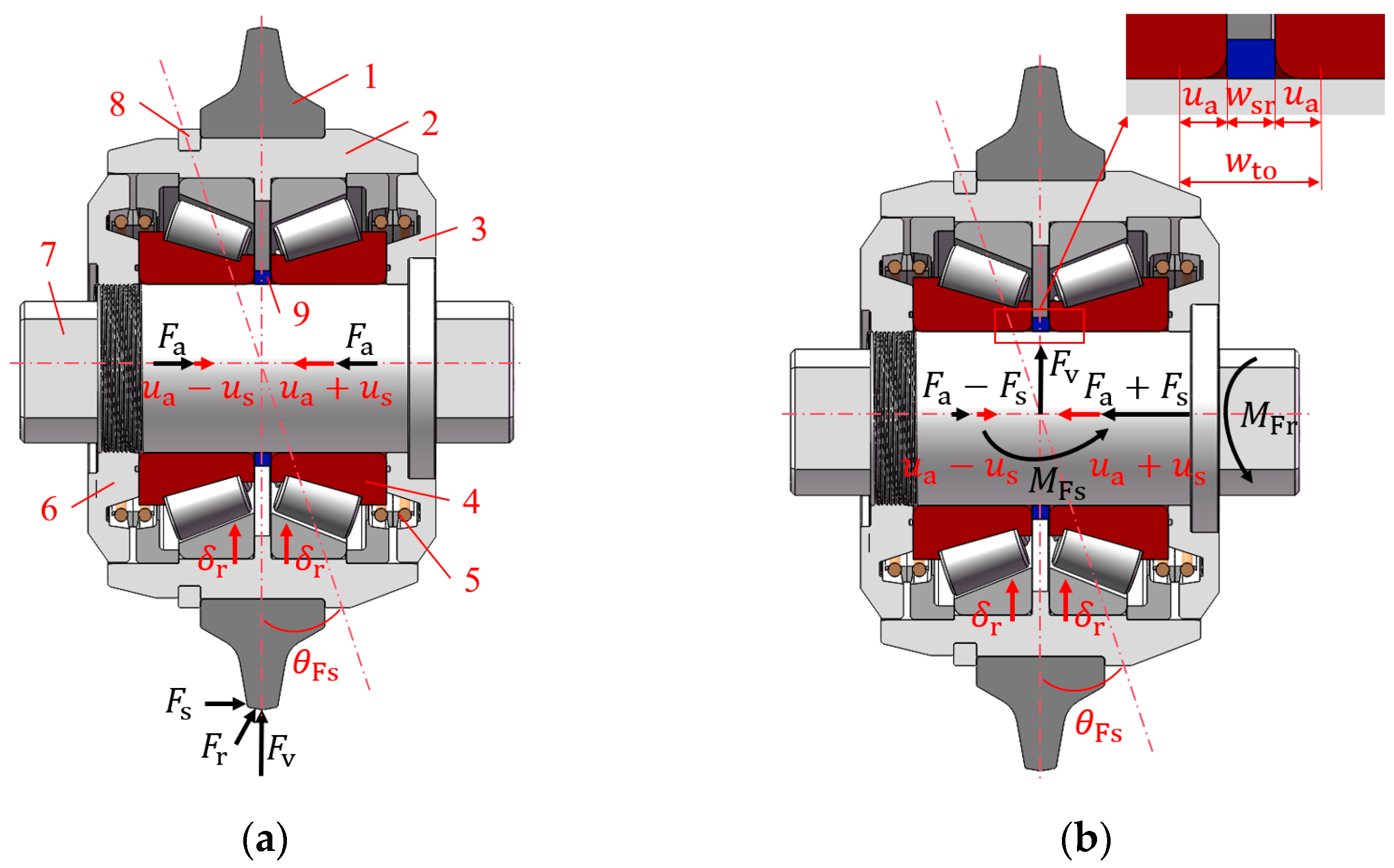
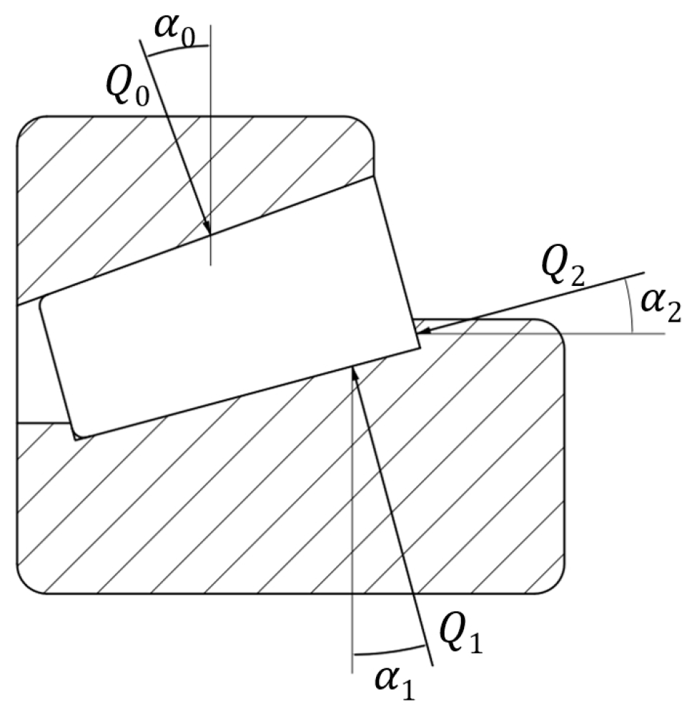
During the rock-breaking process, the disc cutter rolls along the rock surface and applies pressure on the rock, generating a rock-breaking load at the contact area between the cutter ring and the rock. The rock-breaking load consists of three directional forces: the radial force , the lateral force , and the rolling force . The is generated by the thrust of the disc cutter as it feeds into the rock surface, and it is the primary force responsible for rock fragmentation. Under the combined effect of and the rotation of the cutterhead, friction occurs at the contact surface between the cutter ring and the rock, resulting in the . The arises from the combined pressure on both sides of the cutter ring when cutting the rock. As shown in Figure 1a, the preload is generated by the end caps at both ends of the cutter shaft pressing towards the center. The rock-breaking load is transmitted from the cutter ring to the cutter hub and then to the paired tapered roller bearings. The rock-breaking load is equivalently applied at the bearing axis, as shown in Figure 1b. The moves from the cutter ring to the axis. The on the cutter ring is converted into at the axis and an overturning moment . The is converted into the disc cutter friction torque at the axis. Under the action of , , , and , the bearings undergo deformation, which creates the conditions for the generation of bearing friction torque. When induces a rotational tendency in the disc cutter, bearing friction torque is generated. During normal operation of the disc cutter, is approximately equal to the friction torque of the paired bearings in the disc cutter. In the cutter assembly, the preload displacement of the bearing is controlled by adjusting the width of the spacer ring, thereby regulating the preload . As shown in Figure 1b, represents the distance between the small end faces of the inner rings of the paired bearings when the rollers in the disc cutter just make contact with the raceways. This contact state is similar to a transitional fit of the bearing. is the relative displacement of the bearing caused by the at the bearing axis. is the relative angular rotation between the inner and outer rings of the bearing under the action of the . To simplify the analytical method, the loads are converted into displacement-related expressions and superimposed. By combining these expressions with the deformation equations for the forces acting on the rollers, the bearing load states are determined.

Figure 1.
Cross-sectional view and force diagram of the disc cutter: (a) external forces loading; (b) load transmission and preload; 1—cutter ring; 2—cutter hub; 3—right end cap; 4—tapered roller bearing; 5—floating seal; 6—left end cap; 7—cutter shaft; 8—retaining ring; 9—spacer ring.
2.1.1. Solution for the Deformation Displacement of the Rollers
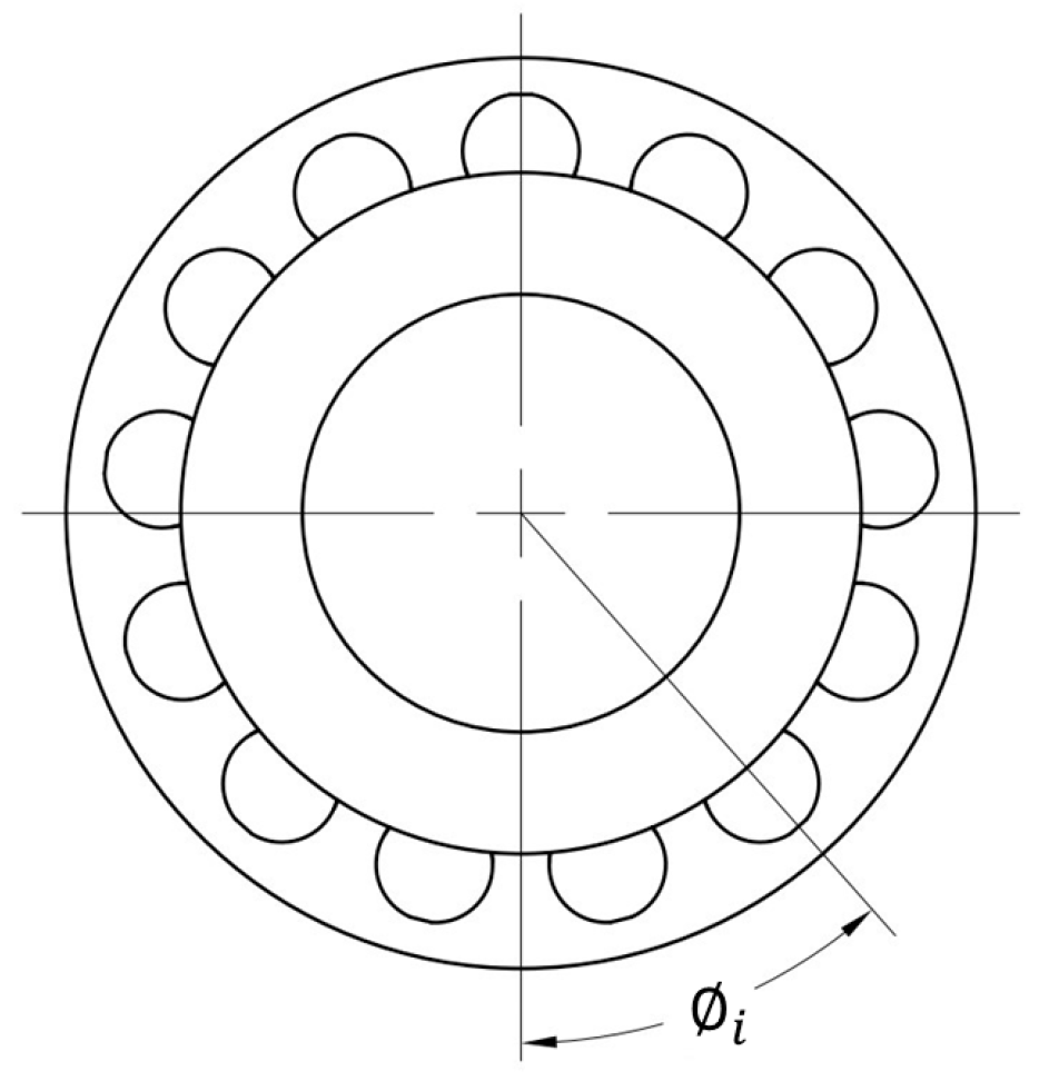
As the disc cutter rotates during the rock-breaking process, the inner race of the bearing undergoes relative motion with the outer race. The force and deformation states of the bearing rollers and raceways change depending on the phase in which the rollers are positioned. Figure 2 shows a schematic diagram of the bearing roller phase angle, where represents the phase angle of the -th roller.
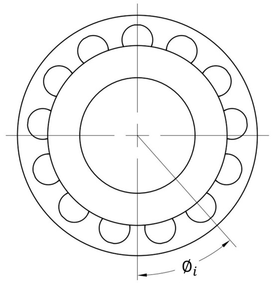
Figure 2.
Schematic diagram of roller phase angle.
To simplify the analysis, the rigid ring assumption is adopted, where the deformation of the bearing under external loads is considered as radial translation and rotation of the inner and outer rings, without any shape changes to the rings.
Under the action of the radial force , a relative radial deformation is generated between the inner and outer rings, as illustrated in Figure 3. The radial deformation component and axial deformation component of the i-th roller at the phase angle are expressed as:
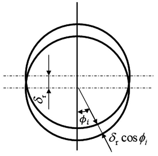
Figure 3.
Radial deformation component diagram of the rollers.
Under the influence of the overturning moment , if a relative radial rotation angle occurs between the inner and outer rings, the radial rotation angle of the roller at the position is given by:
Based on geometric relationships, the radial deformation component and axial deformation component of the -th roller at phase angle are expressed as:
where is the distance from the roller axis to the rotation axis, and is the equivalent diameter of the tapered roller.
Under the combined action of the assembly preload force and the lateral force , as shown in Figure 1b. The radial deformation component and axial deformation component of the -th roller at phase angle are expressed as:
where is the bearing preload displacement, and is the displacement caused by the lateral force .
By combining Equations (1)–(4), the total radial deformation and total axial deformation of the -th roller are expressed as:
2.1.2. Roller Load Calculation
During the loading process of a tapered roller bearing, the force applied in a single direction is decomposed into other directions. Therefore, the force balance of the roller is the result of the combined action of multiple forces. As shown in Figure 4 the contact loads between the tapered roller and the outer ring, inner ring, and flange of the outer ring are denoted as , , , respectively, with corresponding contact angles , , . The contact angles are related to the roller’s half-cone angle and tilt angle.
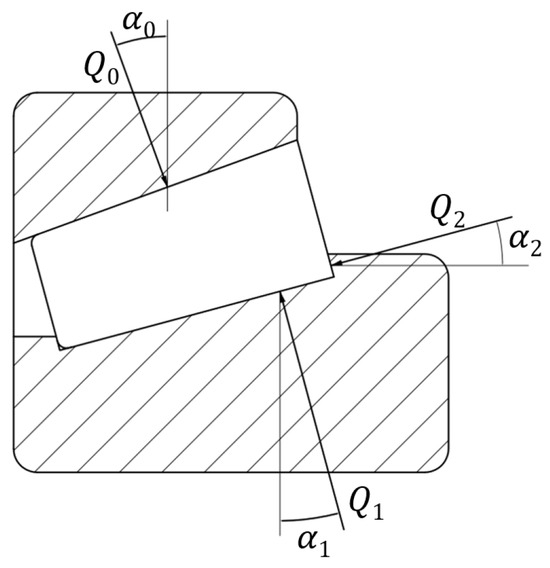
Figure 4.
Schematic diagram of bearing roller loads.
The mechanical equilibrium equations for the roller are:
By selecting the contact load on the outer ring as the reference variable, the equations can be simplified as:
where and are load coefficients:
The contact deformations and between the tapered roller and the raceways of the outer and inner rings can be expressed as:
where and are the compliance coefficients between the roller and the raceways of the outer and inner rings:
where . is the equivalent diameter of the tapered roller. is the raceway diameter. And is the length of the tapered roller.
The i-th tapered roller is typically subjected to both radial and axial loads, resulting in relative radial deformation and axial deformation with respect to the outer ring. As a result, the load applied to the outer race is the combined effect of these deformations. However, since the contact angles between the roller and the inner and outer rings differ, the deformations cannot be directly superimposed. Instead, the axial and radial deformations of the roller need to be projected onto the normal direction of the contact with the outer ring. The projection relationship of these deformations is illustrated in Figure 5.
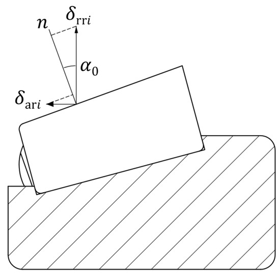
Figure 5.
Deformation projection diagram.
The total deformation displacement of the i-th roller along the contact normal n of the outer ring is given by:
Based on Equations (7)–(11), the total stiffness coefficient at the contact point can be calculated as:
Furthermore, the relationship between the contact load and the total deformation displacement of the i-th roller can be expressed as [30]:
2.1.3. Relationship Between External Forces and Bearing Load
The external forces are decomposed into radial force, axial force, and moment. By establishing the equilibrium equations for each force, the relationship between the external forces and the bearing loads can be derived. By combining the roller contact load expressions and balancing the bearing radial loads with the radial external force, the radial force equilibrium equation of the bearing is derived as:
where j is the index of the paired bearings in the disc cutter. denotes the bearing where and are in the same direction. denotes the bearing where and are in the opposite direction. is the index of the rollers, and z is the number of rollers in the bearing.
By balancing the bearing axial loads with the axial external forces, the axial force equilibrium equation for the bearing is derived as:
The moments generated by the axial and radial components of the contact loads for the j-th bearing are defined as and , respectively. The total moment acting on the j-th bearing is expressed as:
where is the center distance between the pair of tapered roller bearings.
By establishing the balance equation for the overturning moment and the bearing reaction moments, the following equation is obtained:
where is the distance from the point of action of on the cutter ring to the axis.
The rock-breaking loads (, and ) of the disc cutter in various types of rock can be obtained through theoretical calculations [13,14,31], experimental measurements [17,18], and simulation modeling [15,16]. The multifunctional cutter performance experimental system developed by the research group can effectively simulate the rock-breaking process of the disc cutter and measure the rock-breaking loads [32]. In the disc cutter assembly, the preload force is regulated by adjusting the preload displacement. The relationship between the bearing preload and preload displacement will be discussed in Section 3.
At this point, the load distribution of each roller in the bearing during the rock-breaking process can be calculated based on external forces. This provides a theoretical foundation for calculating bearing friction torque using roller loads and establishes a connection between external forces and bearing friction torque.
2.2. Construction of the Bearing Friction Torque Model
The friction experienced by the bearing in the disc cutter during operation mainly consists of three parts. The first part is the rolling friction between the cone rollers and the raceways of the inner and outer rings. The second part is the sliding friction at the contact points between the cone rollers, cage, inner ring flange, and seals. The third part is the friction torque caused by phenomena such as drag losses, splashing, and eddy currents in the lubricant [33]. During the rock-breaking process, the disc cutter operates at a relatively low rotational speed, typically less than 2 revolutions per second. However, the working load can reach several hundred kilonewtons, placing the cutter under low-speed, heavy-load conditions [34]. Furthermore, the cutter is grease-lubricated. Therefore, the friction caused by the lubricant is considered negligible.
The bearing frictional torque discussed in this study primarily considers the rolling frictional resistance between the deformed tapered rollers and the inner and outer raceways, as well as the sliding frictional resistance between the large end faces of the tapered rollers and the inner ring flanges. The friction torque of the paired bearings in the disc cutter can be expressed as:
where and are the rolling friction torque and sliding friction torque of the paired bearings, respectively.
2.2.1. Relationship Between Bearing Load and Rolling Friction Torque
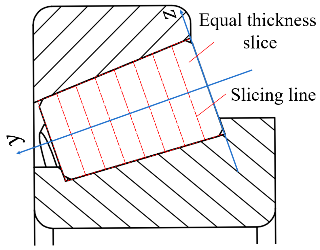
To calculate the rolling frictional torque, the deformation of a single roller is considered as the basis. Under the influence of both external loads and preloading, the tapered roller generates contact forces and deformations along the contact line. The rolling frictional torque of the roller is then calculated based on these contact forces and deformations. Finally, the rolling frictional torques of the pair of tapered rollers in the disc cutter are summed to obtain the total rolling frictional torque. The curvature of the tapered roller varies linearly at different positions along the rotating axis. The tapered roller is treated as a series of slices, with each slice assumed to have a constant curvature. The tapered roller is transformed into a combination of multiple cylindrical segments. The rolling frictional torque for each slice is calculated, and the total frictional torque of the tapered roller is obtained by summing the contributions from all slices [35,36]. The schematic diagram of the slicing process is shown in Figure 6.

Figure 6.
Schematic diagram of roller slicing process.
The rolling friction torque in a slice analysis essentially results from the deformation of the rolling element under force during the rolling process. It is a resistance moment generated due to the non-collinearity between the external force and the actual support force, as illustrated in Figure 7. The resistance torque at the slicing position of the roller can be expressed as:
where is the resistance arm of the slice on the inner raceway, is the resistance arm of the slice on the outer raceway.
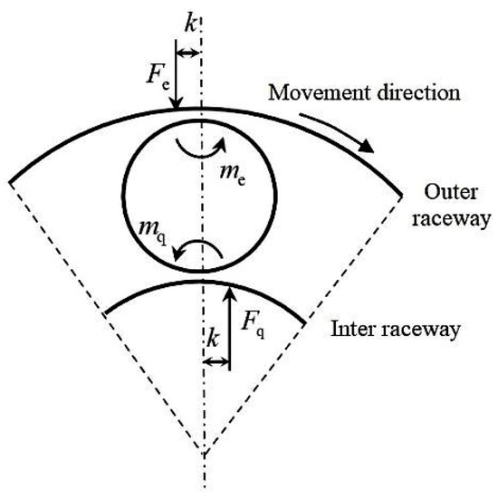
Figure 7.
Force diagram of the roller slice in the vertical direction.
The magnitude of the force offset is related to the semi-major axis of the contact surface. Previous studies suggest [37]:
where is the offset between the external force and the support force. is the semi-major axis of the contact surface.
According to Hertzian contact theory, the semi-major axis can be expressed as:
where is the equivalent radius of curvature, is the maximum contact stress on the contact surface, and is the equivalent elastic modulus.
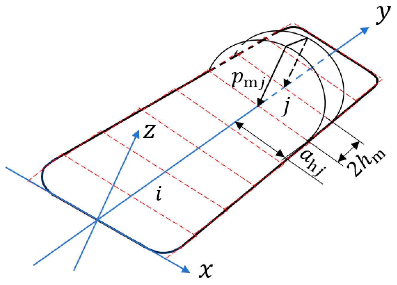
To calculate the loads , , and the maximum contact stress acting on a single slice, the tapered roller is divided into cylindrical slices, each with a width of . The corresponding contact region between the roller and the outer ring is divided into arch-shaped units, each with a width of . The load pressure within each arched element is uniformly distributed along the y-axis and exhibits a Hertzian distribution along the x-axis. The distribution is illustrated in Figure 8.
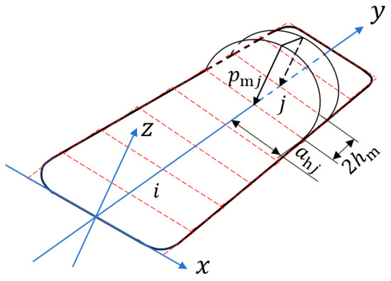
Figure 8.
Schematic diagram of contact load distribution on the roller.
Using the force equilibrium of the cylindrical slices with the outer ring, the following equilibrium equation can be established:
However, this equation cannot directly solve for on the strip elements. To address this, the displacement equation between the strip elements and the roller is introduced. Based on the Boussinesq solution for elastic half-space, the displacement at the center of element caused by the stress on element is given by:
The elastic deformation of the roller is expressed as:
Together with Equations (22)–(24), this forms a system of + 1 linear equations, which can be solved to determine the maximum contact stress for the strip elements in the outer ring contact region and the elastic deformation .
In conjunction with Figure 8, the load exerted by the outer ring on the slice can be expressed as:
Similarly, by repeating the above process, the load exerted by the inner ring on the slice can be determined.
At this point, the calculation of the frictional torque for a specific slice of the tapered roller has been completed. Combining Equation (19), the rolling friction resistance torque of the pair of tapered roller bearings in the disc cutter can be expressed as:
where z is the number of rollers, and is the number of slices.
2.2.2. Relationship Between Bearing Load and Sliding Friction Torque
The sliding friction torque of the disc cutter bearings primarily originates from the sliding friction force between the large end of the tapered roller and the inner ring flange. The force state is illustrated in Figure 9.

Figure 9.
Schematic diagram of sliding friction torque.
The sliding friction torque at the contact point between the roller and the outer ring can be expressed as:
where e is the effective contact length between the inner ring flange and the tapered roller end face.
The expression for is:
where is the sliding friction coefficient between the inner ring and the roller, and is the normal load on the tapered roller’s motion surface.
The total sliding friction torque within the tapered roller bearing can be expressed as:
3. Simulation Analysis of the Relationship Between Bearing Preload and Preload Displacement
To establish the relationship between the preload force and preload displacement, this study focuses on the HH926749/10 tapered roller bearing used in a 19-inch disc cutter. A simulation analysis of the bearing preload process will be performed.
3.1. Establishment of the Bearing Finite Element Model
3.1.1. Material Properties and Mesh Division
Since the simulation primarily focuses on the axial deformation of the bearing under axial assembly pressure, the 3D model excludes the bearing cage, which has minimal impact on the simulation results. The fillets on the inner and outer rings and the chamfers on the rollers are retained to ensure simulation accuracy while minimizing computational costs. The simulation is conducted using a combined HyperMesh and Abaqus approach. The bearing material is defined as isotropic, and the material model parameters are listed in Table 1.

Table 1.
Bearing material parameters.
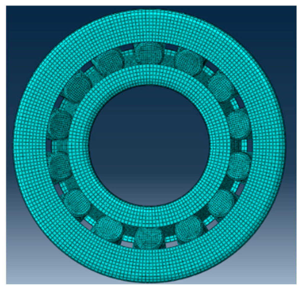
To enhance the quality of the mesh and ensure the finite element model produces accurate and reasonable results, hexahedral elements with better computational precision and anti-distortion performance were used for the mesh generation of all bearing components in HyperMesh. The 2D mesh nodes of the model were manually optimized to improve the mesh quality, ensuring more precise finite element calculations. The mesh quality parameters are shown in Table 2. After optimization, the bearing model contains 126,800 elements, all of which are 8-node hexahedral linear reduced-integration elements (C3D8R). The final finite element mesh model of the tapered roller bearing is shown in Figure 10.
Table 2.
Element division quality parameters extremes.
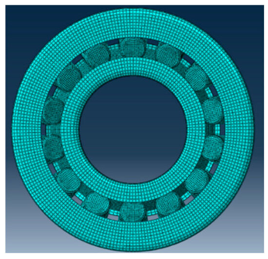
Figure 10.
Finite element model of the bearing.
3.1.2. Setting Analysis Step and Interaction Parameters
In the bearing preloading process, the inner ring of the bearing undergoes axial deformation due to the thrust from the end cap. The cone rollers transfer the force to the outer ring through the displacement of the inner ring, while the outer ring remains stationary due to the action of the hub flange. Throughout this process, the movement of all components is driven by the thrust on the inner ring’s end face. The inner ring’s movement speed is relatively slow, which can be regarded as a static equilibrium state. Therefore, the simulation analysis step for the preloading process is created as a single static analysis step.
Three surface-to-surface contact pairs are defined: the large end face of the roller and the inner ring flange, the inner ring raceway and the tapered surface of the roller, and the outer ring raceway and the tapered surface of the roller. For the primary and secondary surfaces, the bearing material parameters are set according to bearing steel. Although the elastic moduli are the same, it is known from practical applications that the inner and outer rings of the bearing are interference-fitted with the shaft and tool body, respectively. The structural stiffness of the rings is much greater than that of the rollers, and the rollers are the main deformed components under load. Therefore, the inner and outer rings, which have greater stiffness, are selected as the master surfaces, while the surfaces related to the rollers are selected as the secondary surfaces. The normal contact property for all surface-to-surface contacts is set to hard contact, and the tangential contact properties are set using penalty functions. The friction coefficient for the contact pair between the roller end face and the inner ring’s edge is set to 0, while the friction coefficient for the other contact pairs is set to 0.15.
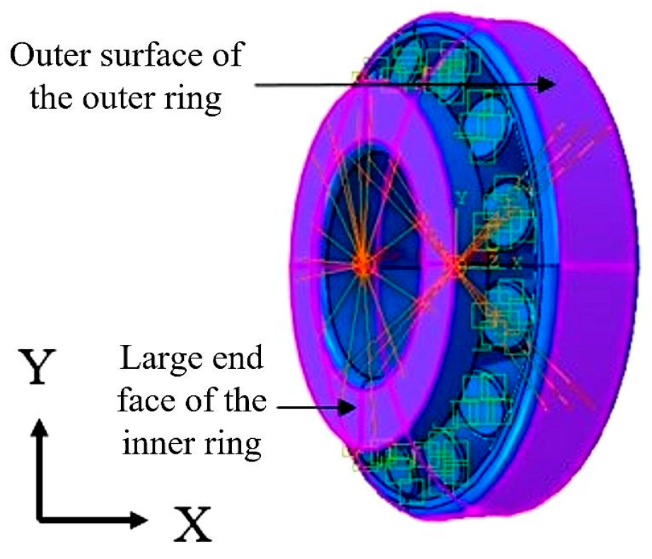
3.1.3. Setting of Boundary Conditions
According to the bearing preloading of the disc cutter, the outer surface of the bearing outer ring is in a tight fit with the hub of the cutter. Therefore, all six degrees of freedom of the outer surface of the bearing are fixed, while no constraints are applied to other surfaces of the outer ring. The inner ring, which undergoes displacement due to the thrust from the end cap, has a specified displacement applied to its large end face. The final constrained model of the bearing is shown in Figure 11.

Figure 11.
Model diagram of bearing constraint.
From the actual assembly and usage of the 19-inch disc cutter, it is known that the working preload displacement of a single-bearing inner ring is typically adjusted to be between 0.05 mm and 0.125 mm under the influence of the spacer ring. In addition, during the modeling of the tapered roller bearing, an initial axial clearance of 0.05 mm was reserved to ensure the reliability of contact and simulation. Therefore, the simulation preloading displacement range for a single bearing is between 0.1 mm and 0.175 mm. To cover the extreme cases as much as possible, the simulation preloading displacement range is set between 0.095 mm and 0.2 mm.
3.2. Results of Finite Element Analysis
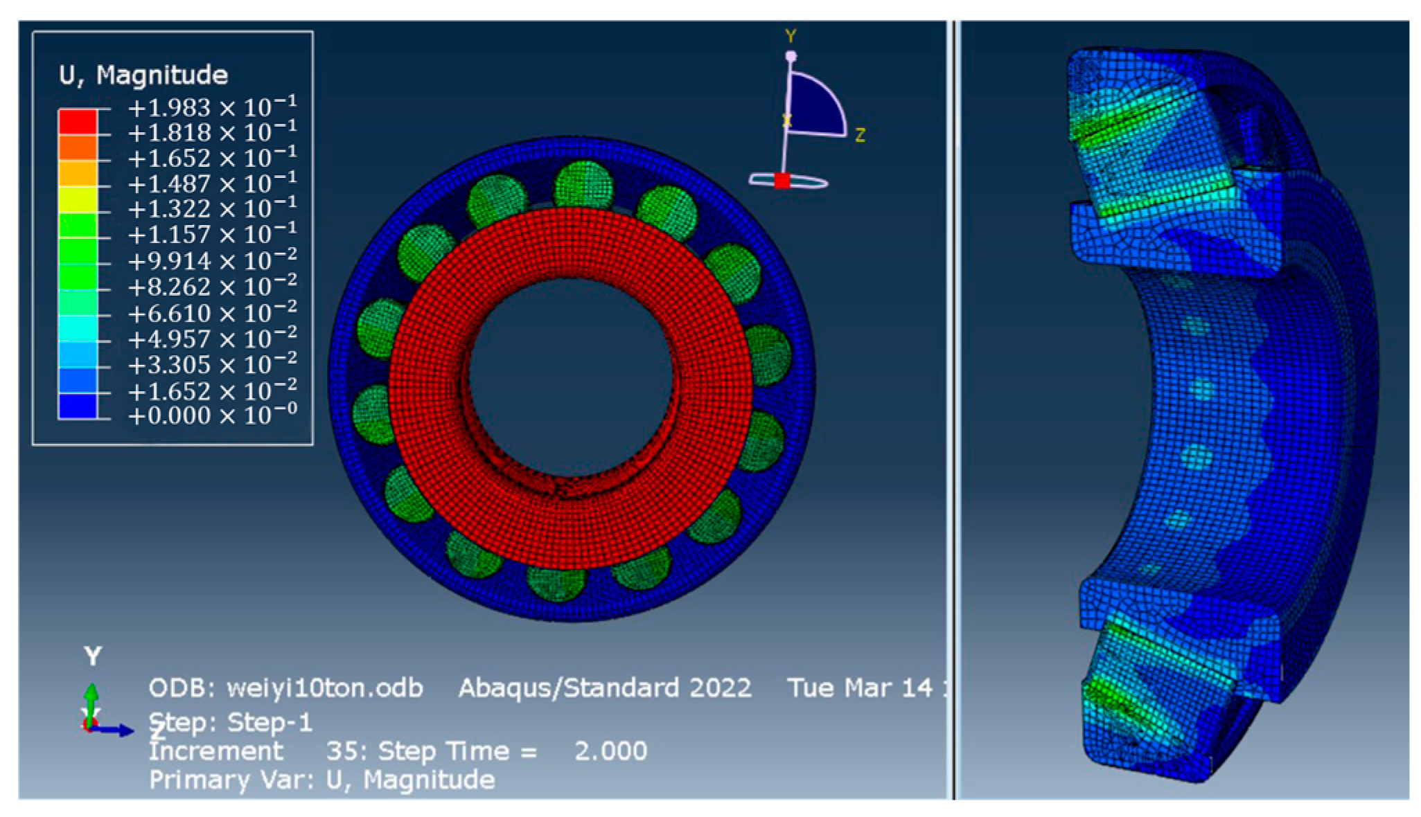
3.2.1. Analysis of Bearing Preload
Figure 12 shows the displacement cloud diagram of the HH926749/10 bearing under a preload displacement of 0.2 mm. Although the displacement of the bearing inner ring is applied only to the large end face, the overall displacement of the inner ring elements is essentially uniform. The displacement along the contact line between the bearing rollers and the inner ring is approximately 0.10 mm. This displacement primarily consists of two components. The first component arises from the axial movement of the inner ring, causing deformation of the roller due to compression from the tapered surface of the inner ring. The second component is the sliding displacement of the roller, supported by the inner ring. The displacement at the large end of the bearing roller is 0.12 mm, which is greater than the displacement at the contact area between the roller and the inner ring. This is because the end face of the roller is also directly compressed by the inner ring flange. The outer surface of the outer ring of the rolling bearing is fixed, so the overall displacement of the unit is essentially zero. In summary, the displacement of each part of the bearing is generally consistent with actual conditions, demonstrating the validity and rationality of the parameter settings in the simulation model.
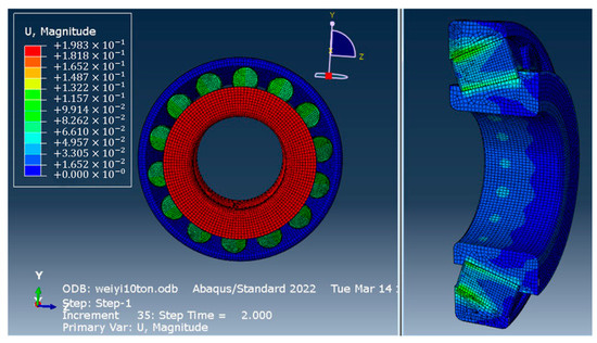
Figure 12.
Cloud diagram of HH926749/10 bearing displacement.
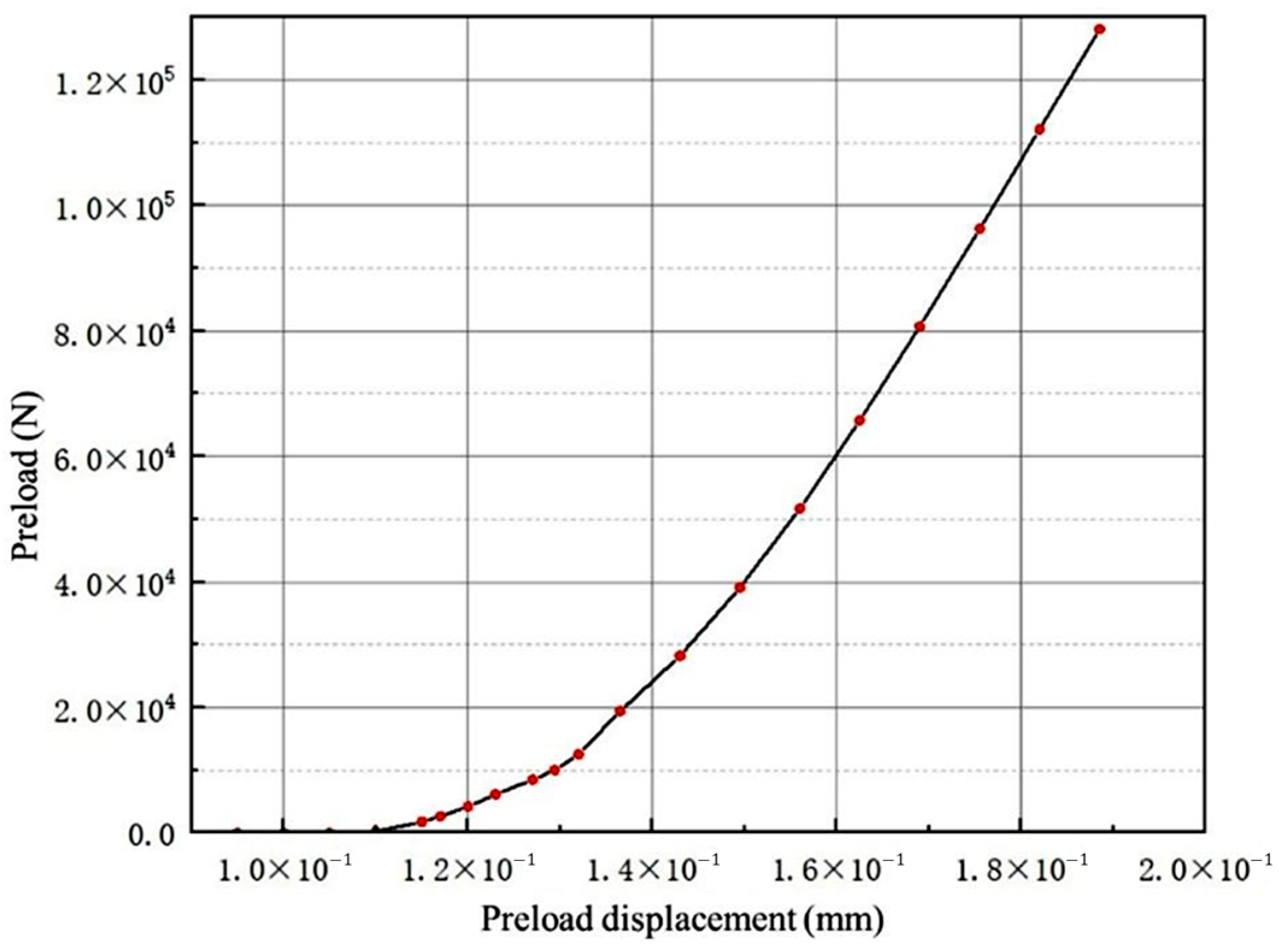
3.2.2. Relationship Between Preload and Preload Displacement
Since the displacement is applied at the large end face of the bearing inner ring in the preload simulation process, the required preload force can be extracted at the coupling point on the large end face of the inner ring. Figure 13 shows the relationship between preload displacement and the preload force.
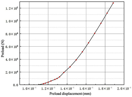
Figure 13.
Relationship chart between preload displacement and preload force.
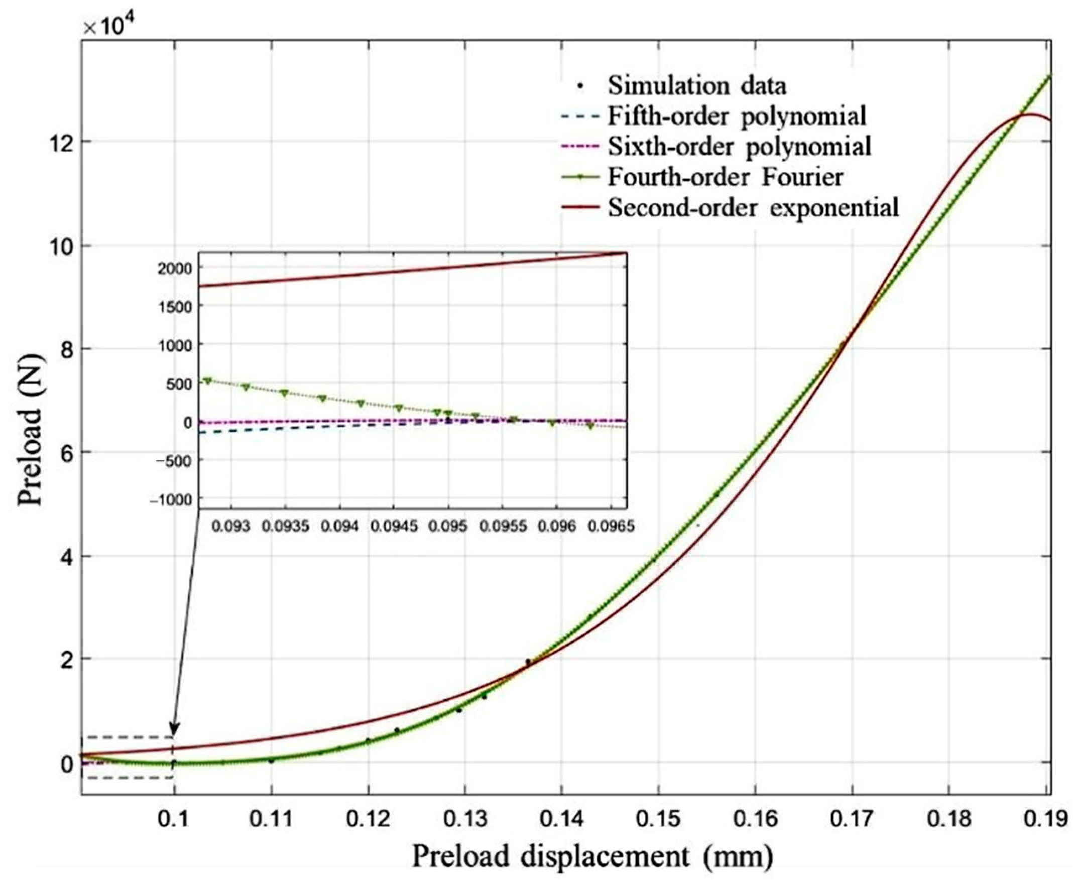
Taking the preload displacement as the independent variable of the fitting function and the preload force as the dependent variable, 20 sets of simulation data were used for fitting. There are various types of data fitting methods, and the selection of the fitting function is a key factor affecting the accuracy of data fitting. Given the abundance of simulation data and the similarity between the simulation result curve and an exponential function, three types of functions—polynomial interpolation, Fourier trigonometric functions, and exponential functions—were selected for fitting analysis of the simulation data in MATLAB 2021.
Table 3 shows the results of the fitting using the three types of functions. The fitting results are evaluated based on multiple parameters, including root mean square error (RMSE), sum of squared errors (SSE), multiple correlation coefficient (R-sq), and adjusted multiple correlation coefficient (Adj R-sq). As shown in Table 3, the greater the number of coefficients (Coeff) in the function model, the better the fitting performance tends to be. However, the evaluation parameters mentioned above only reflect the relationship between the sample points and the fitting function. Excessively high orders in the fitting function can lead to overfitting, resulting in significant discrepancies between values outside the sample points and the predicted values. Therefore, it is necessary to combine graphical analysis with practical considerations to avoid overfitting the function.
Table 3.
Fitting results parameter table.
Figure 14 shows the curves obtained after fitting with different functions. Except for the exponential function, the other fitting functions coincide almost completely within the range of 0.11 mm to 0.1885 mm, with the main difference occurring between 0.09 mm and 0.11 mm. The fourth-order Fourier function shows that, in the low preload displacement range, the preload force initially decreases and then increases. However, in the actual bearing preload process, the preload force gradually increases in the low preload displacement range. The fourth-order Fourier function demonstrates overfitting. The trends of the fifth-order polynomial and sixth-order polynomial are generally consistent with the actual situation. From Table 3, the performance of the sixth-order polynomial is superior to that of the fifth-order polynomial. Therefore, the sixth-order polynomial is considered the optimal fitting function.
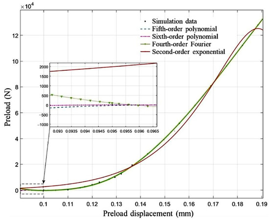
Figure 14.
Fitting curves.
The relationship between preload force and preload displacement can be expressed as:
where is the preload displacement, are the polynomial coefficients, as shown in Table 4.
Table 4.
Polynomial parameters.
4. Experiments of Disc Cutter Preload Displacement and Friction Torque
The study focuses on the 19-inch disc cutter, with the bearing model HH926749/10. The experiment aims to measure the preload displacement and bearing friction torque of the disc cutter under different preloading forces.
4.1. Experiment of Disc Cutter Preload Displacement
The purpose of this experiment is to measure the preload force and preload displacement during the assembly of the disc cutter, in order to verify the relationship between preload force and preload displacement through fitting.
- Experimental setup
As shown in Figure 15, the experimental setup includes a hydraulic press with a maximum working pressure of 100 tons and a control accuracy of 0.5 tons. The experimental disc cutter consists of only the bearing, cutter hub, and cutter ring. The bearing inner ring base is placed on the hydraulic press, and the disc cutter is then positioned on the base, as shown in Figure 16a. The other end of the disc cutter’s bearing inner ring is connected to the hydraulic press through a sleeve. During the experiment, preload is applied to the bearing in the disc cutter by loading through the hydraulic press.
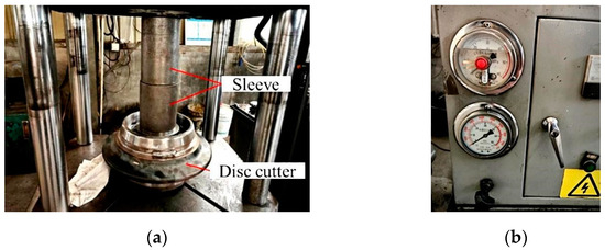
Figure 15.
Experimental setup: (a) hydraulic press; (b) hydraulic gauge.

Figure 16.
Measurement principle and physical diagram of the disc cutter: (a) principle; (b) physical.
- Preload displacement measurement
The preload displacement of the bearing is measured using an indirect measurement method, as shown in Figure 16. The distance between the calibration plate and the bearing inner race is measured, and the preload displacement is calculated. An electronic vernier caliper, with a precision of 0.01 mm, is used for distance measurement.
where is the distance measured after the loading pressure has stabilized. is the initial distance measured after the maximum pressure is unloaded, in order to avoid the influence of the initial gap within the disc cutter.
- Analysis of preload displacement experimental results
The preload displacement measurement results are shown in Table 5.
Table 5.
Preload displacement measurement results.
Figure 17 shows a comparison between the experimental fitting curve and the simulation fitting curve. There is a certain difference between the experimental and simulation results, with an average relative error of approximately 13.6%. Overall, the experimental and simulation results are in good agreement, which validates the reliability of the preload force and preload displacement relationship in the simulation model.
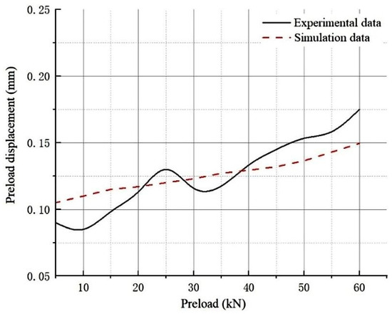
Figure 17.
Experimental fitting curve and simulation polynomial curve.
- Error analysis
The forces and contact conditions in the simulation model are relatively ideal, resulting in a more uniform force distribution on the roller and a smaller variation in preload force compared to the actual process. During the experiment, although the measurement points on the bearing inner ring surface were kept as consistent as possible within the same region, slight variations in the actual measurement positions still occurred. This led to some data points where the preload force increased while the actual displacement remained unchanged or even decreased.
4.2. Experiment of Disc Cutter Bearing Friction Torque
This experiment was conducted under the no-load condition of the disc cutter. The objective is to verify the reliability of the bearing friction torque theoretical model by measuring the preload force and the bearing friction torque of the disc cutter.
- Experimental setup
The disc cutter was positioned in the same manner as shown in Figure 15. The bearing friction torque of the disc cutter is measured using the balance measurement method [38], as depicted in Figure 18. The torque wrench used for measurement has an accuracy of 0.5 N∙m. After applying the preload force, the torque wrench is slowly used to apply thrust until it causes the disc cutter to rotate. At this point, the inner ring of the bearing remains stationary under the hydraulic press, while the outer ring rotates. The reading from the torque wrench represents the bearing friction torque of the disc cutter.
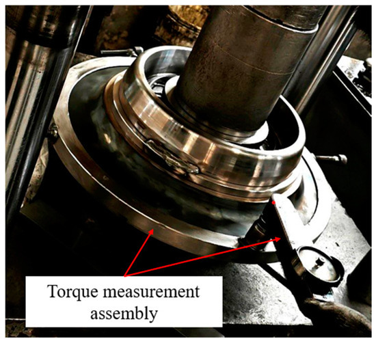
Figure 18.
Experimental setup of bearing friction torque measurement.
- Analysis of friction torque experimental results
The bearing friction torque measurement results under no-load conditions are shown in Table 6.
Table 6.
Friction torque results.
In the same five sets of preload forces and no-load conditions as the experiment, the bearing friction torques are calculated using the theoretical model. Table 7 shows the constant parameter values used in the theoretical model. Figure 19 shows a comparison between the theoretical and experimental values of the bearing friction torque. At a preload force of 5 kN, the maximum discrepancy between the experimental and theoretical friction torque is observed, with a maximum error of approximately 5 N∙m. As the preload force increases, the error between the theoretical and experimental values initially decreases and then increases, eventually reaching a fixed value. The average relative error is approximately 13.3%, which validates the reliability of the bearing rolling friction torque model.
Table 7.
Constant parameter values.
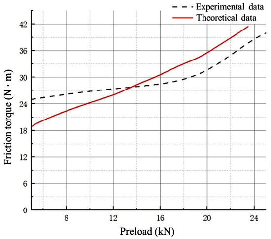
Figure 19.
Theoretical and experimental comparison of bearing friction torque.
- Error analysis
The actual bearing roller material consists of two components, and the deformation calculation of the rollers in the theoretical model is slightly smaller than the actual deformation. As a result, the rolling friction torque calculated by the model is also relatively smaller. This causes the experimental friction torque of the disc cutter to be greater than the theoretical friction torque at low preload forces. As the preload increases, the roller deformation does not increase linearly with the preload force, and the contribution of rolling friction torque decreases. At this point, the friction torque is more influenced by the sliding friction of the bearing, and thus the difference between the experimental and theoretical values becomes smaller at higher preload forces, and the trends are more consistent.
5. Discussion and Conclusions
This study investigates the impact of disc cutter preload force on bearing friction torque under rock-breaking conditions. By analyzing the propagation of rock-breaking loads within the disc cutter, a model was established to describe the deformation displacement and load distribution of the bearing rollers in the cutter. Based on the force equilibrium equation, the relationship between rock-breaking load, preload force, and bearing load was developed. The bearing friction torque is decomposed into rolling and sliding friction torques. Using the Hertzian contact torque and the slice method, a calculation model for the sliding friction torque of the bearings is established. This model is then used to derive the relationship between bearing load and friction torque. By combining the bearing load distribution model, the influence of rock-breaking load and preload force on the bearing friction torque is determined. Finite element analysis is performed to determine the impact of preload displacement on the preload force. Using simulation data, a fitting relationship between preload displacement and preload force is established. Based on the variation trends of preload displacement and preload force in practical situations, the phenomenon of overfitting in higher-order fitting functions is identified, and a sixth-order polynomial fitting is found to be the optimal fitting function. Experiments on the preload displacement and friction torque of the bearings in the disc cutter were conducted. The results show that the average relative error between the simulation values and experimental results for the relationship between preload force and preload displacement is approximately 13.6%. Overall, the experimental results are in good agreement with the simulation results. The average relative error between the theoretical and experimental results for the relationship between preload force and friction torque is approximately 13.3%, with both showing similar trends. The experiments validate the reliability of both the theoretical model and the simulation model.
Despite these achievements, the proposed method is not without limitations. First, the dynamic loads during TBM operation have a significant impact on the friction torque of the disc cutter. The rolling force is proportional to the external friction torque of the cutter, while the radial force and lateral force have a positive correlation with the bearing friction torque. In future research on optimizing the preload of the disc cutter, the effects of dynamic loads and vibrations on cutter eccentric wear and bearing lifespan should be considered. Secondly, due to the limitations of the existing experimental setup, it is challenging to conduct experiments with applied rock-breaking loads. This experiment only verified the relationship between preload and friction torque in the theoretical model. Future work should focus on improving the experimental setup, increasing the amount of experimental data, and conducting validation experiments under the combined action of rock-breaking loads and preload. Finally, the theoretical and simulation models were simplified. This paper primarily focuses on the rolling friction torque and sliding friction torque generated by roller deformation, while neglecting factors such as lubrication, temperature, surface roughness, and manufacturing errors, which resulted in some discrepancies between experimental and theoretical values. The simulation model also overlooks factors like bearing dimensional accuracy, assembly precision and material variations, leading to discrepancies between experimental and simulation results. Future work should aim to further improve both the theoretical and simulation models to better align with actual operating conditions.
Author Contributions
Conceptualization, G.H. and H.L.; methodology, G.H., C.Y. and H.L.; SOFTWARE, G.H., H.L. and C.Y.; validation, G.H., H.L. and C.Y.; formal analysis, G.H. and C.Y.; investigation, G.H. and H.L.; resources: H.Z., G.H. and Z.Z.; data curation, G.H. and C.Y.; writing—original draft preparation, G.H. and C.Y.; writing—review and editing, G.H., C.Y., H.L., H.Z. and Z.Z.; visualization, G.H.; supervision, H.Z.; project administration, H.Z.; funding acquisition, H.Z., G.H. and Z.Z. All authors have read and agreed to the published version of the manuscript.
Funding
The work was financially supported by Special funding support for the Yuelu Mountain National University Science and Technology City “Ranking the Top of the List” Research Project: (Tunnel Boring Machine High-performance Long-life Cutting Tools) and the Graduate Research and Innovation Projects of Hunan Province under Grant CX20240193. This work also was sponsored by the Graduate Innovation Project of Central South University.
Data Availability Statement
Data are contained within the article.
Conflicts of Interest
The authors declare no conflicts of interest.
References
- Fu, J.; Liu, H.; Feng, L.; Wu, D.; Tang, H.; Xia, Y. Wear performance of modified H-13 and H418E steels for TBM disc cutter ring. Eng. Fail. Anal. 2024, 156, 107783. [Google Scholar] [CrossRef]
- Shen, X.; Chen, X.; Fu, Y.; Cao, C.; Yuan, D.; Li, X.; Xiao, Y. Prediction and analysis of slurry shield TBM disc cutter wear and its application in cutter change time. Wear 2022, 498, 204314. [Google Scholar] [CrossRef]
- Hu, G.; Zhao, H.; Fu, J.; Xue, J.; Xia, Y. Impact fracture failure analysis and mechanism study of a TBM disc cutter ring. Eng. Fail. Anal. 2024, 163, 108508. [Google Scholar] [CrossRef]
- Yang, H.; Liu, B.; Wang, Y.; Li, C. Prediction model for normal and flat wear of disc cutters during TBM tunneling process. Int. J. Geomech. 2021, 21, 6021002. [Google Scholar]
- Hu, G.; Yu, L.; Zhang, Z.; Yang, C.; Fu, J.; Xue, J.; Zhao, H.; Xia, Y.; Yu, L.; Chang, L. Research on fatigue failure analysis and fracture mechanisms of a cutter ring in tunnel boring machine. Eng. Fail. Anal. 2025, 169, 109232. [Google Scholar] [CrossRef]
- Sun, R.; Mo, J.; Zhang, M.; Su, Y.; Zhou, Z. Cutting performance and contact behavior of partial-wear TBM disc cutters: A laboratory scale investigation. Eng. Fail. Anal. 2022, 137, 106253. [Google Scholar] [CrossRef]
- Ge, Y.; Liu, Y.; Lin, P.; Xu, Z. Effects of rock properties on the wear of TBM disc cutter: A case study of the Yellow River diversion project, China. Int. J. Geomech. 2022, 22, 4022011. [Google Scholar]
- Pan, Y.; Liu, Q.; Peng, X.; Kong, X.; Liu, J.; Zhang, X. Full-Scale Rotary Cutting Test to Study the Influence of Disc Cutter Installment Radius on Rock Cutting Forces. Rock. Mech. Rock. Eng. 2018, 51, 2223–2236. [Google Scholar] [CrossRef]
- Huang, Y.; Hao, R.; Li, J.; Wang, H.; Guo, J. Failure Analysis on the Chordal Eccentric Wear of Disk Cutter in Shield Machine. J. Fail. Anal. Prev. 2024, 24, 817–827. [Google Scholar] [CrossRef]
- Cheng, Y.F. Mechanism Analysis and Maintenance of Cutter Head Damage Phenomenon in TBM Construction. Plant Maint. Eng. 2022, 4, 112–113. [Google Scholar] [CrossRef]
- Tang, H. Improvement of Shield Cutters Used in Guangzhou Mass Transit Rail Line. Rock Drill. Mach. Pneum. Tools 2023, 49, 31–36. [Google Scholar] [CrossRef]
- Li, F.; Li, S.X.; Liu, Q.Q. Wear and wear reduction measures of shield cutters. J. Mach. Des. 2021, 38, 126–130. [Google Scholar] [CrossRef]
- Sun, J.; Wang, K.; Wei, J.; Shang, Y.; Sun, C.; Ma, F. A mechanics model of constant cross-section type disc cutter based on dense core forming mechanism. Tunn. Undergr. Space Technol. 2023, 140, 105301. [Google Scholar] [CrossRef]
- Zhang, K.; Zhang, Y.; Liu, J.; Lin, L.; Zheng, X. Research on Spatial Kinematics and Cutting Load Characteristics of TBM Disc Cutters. Geotech. Geol. Eng. 2023, 41, 337–352. [Google Scholar] [CrossRef]
- Zhang, Z.; Zhang, K.; Dong, W.; Zhang, B. Study of Rock-Cutting Process by Disc Cutters in Mixed Ground based on Three-dimensional Particle Flow Model. Rock. Mech. Rock. Eng. 2020, 53, 3485–3506. [Google Scholar] [CrossRef]
- Labra, C.; Rojek, J.; Onate, E. Discrete/Finite Element Modelling of Rock Cutting with a TBM Disc Cutter. Rock. Mech. Rock. Eng. 2017, 50, 621–638. [Google Scholar] [CrossRef]
- Entacher, M.; Lorenz, S.; Galler, R. Tunnel boring machine performance prediction with scaled rock cutting tests. Int. J. Rock. Mech. Min. Sci. 2014, 70, 450–459. [Google Scholar] [CrossRef]
- Thyagarajan, M.V.; Rostami, J. Study of cutting forces acting on a disc cutter and impact of variable penetration measured by full scale linear cutting tests. Int. J. Rock. Mech. Min. Sci. 2024, 175, 105675. [Google Scholar] [CrossRef]
- Zhou, X.; Zhang, Y.; Gong, G.; Yang, H. Experimental Study on Partial Wear of TBM Disc Cutter. In Proceedings of the 2024 Prognostics and System Health Management Conference (PHM), Stockholm, Sweden, 28–31 May 2024; pp. 260–265. [Google Scholar]
- Hammami, M.; Martins, R.; Fernandes, C.; Seabra, J.; Abbes, M.S.; Haddar, M. Friction torque in rolling bearings lubricated with axle gear oils. Tribol. Int. 2018, 119, 419–435. [Google Scholar] [CrossRef]
- Houpert, L. Ball bearing and tapered roller bearing torque: Analytical, numerical and experimental results. Tribol. Trans. 2002, 45, 345–353. [Google Scholar] [CrossRef]
- Cai, G.; Hou, Y.; Wang, X.; Sun, S.; Zhang, Y.; Wang, N. A measurement method for friction torque between rollers and raceways of tapered roller bearings under radial heavy load conditions. Tribol. Int. 2024, 200, 110071. [Google Scholar] [CrossRef]
- Wu, C.; Yang, K.; Ni, J.; Lu, S.; Yao, L.; Li, X. Investigations for vibration and friction torque behaviors of thrust ball bearing with self-driven textured guiding surface. Friction 2023, 11, 894–910. [Google Scholar] [CrossRef]
- Liu, J.; Yan, Z.; Shao, Y. An investigation for the friction torque of a needle roller bearing with the roundness error. Mech. Mach. Theory 2018, 121, 259–272. [Google Scholar] [CrossRef]
- Heras, I.; Aguirrebeitia, J.; Abasolo, M.; Coria, I.; Escanciano, I. Load distribution and friction torque in four-point contact slewing bearings considering manufacturing errors and ring flexibility. Mech. Mach. Theory 2019, 137, 23–36. [Google Scholar] [CrossRef]
- Escanciano, I.; Heras, I.; Macareno, L.M.; Aguirrebeitia, J. An engineering approach to assess friction torque in generally loaded four-point contact slewing bearings. Mech. Mach. Theory 2024, 192, 105542. [Google Scholar] [CrossRef]
- Liu, Y.; Fan, X.; Wang, J.; Liu, X. An Investigation for the Friction Torque of a Tapered Roller Bearing Considering the Geometric Homogeneity of Rollers. Lubricants 2022, 10, 154. [Google Scholar] [CrossRef]
- Zhang, C.; Gu, L.; Mao, Y.; Wang, L. Modeling the frictional torque of a dry-lubricated tapered roller bearing considering the roller skewing. Friction 2019, 7, 551–563. [Google Scholar] [CrossRef]
- Wingertszahn, P.; Koch, O.; Maccioni, L.; Concli, F.; Sauer, B. Predicting Friction of Tapered Roller Bearings with Detailed Multi-Body Simulation Models. Lubricants 2023, 11, 369. [Google Scholar] [CrossRef]
- Yuan, Y.; Wang, J.; Ren, L.; Chen, J. Influence of axial clearance on load distribution in double supported tapered roller bearings of wind turbine main shaft. Proc. Inst. Mech. Eng. Part C J. Mech. Eng. Sci. 2024, 238, 10536–10552. [Google Scholar] [CrossRef]
- Sun, B.; Guo, W.; Zhu, D.H.; Song, L.W.; Liu, J.Q.; Sun, H.Y. The Improvement of TBM Cutter’s force Formula Based on CSM Model. Mach. Des. Res. 2015, 31, 121–124. [Google Scholar] [CrossRef]
- Ning, B.; Xia, Y.; Lin, L.; Zhang, X.; He, Y.; Liu, Y. Experimental study on the adaptability of cutters with different blade widths under hard rock and extremely hard rock conditions. Acta Geotech. 2020, 15, 3283–3294. [Google Scholar] [CrossRef]
- Xu, C.; Chen, Q.; Li, B.X.; Yuan, W. Relationship between axial loading and tightening torque of tapered roller bearing. Machinery 2012, 39, 24–26. [Google Scholar]
- Huo, J.Z.; Sun, X.L.; Li, G.Q.; Li, T. The structural design and dynamic characteristics of a new type of disc cutter under sliding support. J. Harbin Eng. Univ. 2015, 36, 1509–1514. [Google Scholar]
- Li, Y.; Gao, Y. Internal load distribution of single-row tapered roller bearings doubly supporting main shaft of wind turbine. Adv. Mech. Eng. 2022, 14, 1669512079. [Google Scholar] [CrossRef]
- Stirling, J. Internal Load Modelling of Tapered-Roller Main Bearings in Wind Turbines. Ph.D. Thesis, University of Strathclyde, Glasgow, UK, 2023. [Google Scholar]
- Wei, Q.L. On the Rolling Friction Law of Coulombian Bodies. J. Wuhan. Univ. Sci. Technol. 1985, 2, 108–110. [Google Scholar]
- Wrzochal, M.; Adamczak, S.; Domagalski, R.; Piotrowicz, G.; Wnuk, S. A New Device Proposed for the Industrial Measurement of Rolling Bearing Friction Torque. Strojniski Vestn.-J. Mech. Eng. 2022, 68, 610–622. [Google Scholar] [CrossRef]


Disclaimer/Publisher’s Note: The statements, opinions and data contained in all publications are solely those of the individual author(s) and contributor(s) and not of MDPI and/or the editor(s). MDPI and/or the editor(s) disclaim responsibility for any injury to people or property resulting from any ideas, methods, instructions or products referred to in the content. |
© 2025 by the authors. Licensee MDPI, Basel, Switzerland. This article is an open access article distributed under the terms and conditions of the Creative Commons Attribution (CC BY) license (https://creativecommons.org/licenses/by/4.0/).