Article

Method for Maintaining Technical Condition of Marine Diesel Engine Bearings

1
Department of Ship’s Power Plant, National University “Odessa Maritime Academy”, 8, Didrikhson Street, 65052 Odessa, Ukraine
2
Department of Cars and Carriage Facilities, State University of Infrastructure and Technologies, Kyrylivska Street, 9, 04071 Kyiv, Ukraine
3
Institute of Automotive Engineering, Faculty of Mechanical Engineering, Brno University of Technology, Technická 2896/2, 616 69 Brno, Czech Republic
*
Author to whom correspondence should be addressed.
Lubricants 2025, 13(4), 146; https://doi.org/10.3390/lubricants13040146
Submission received: 25 February 2025 / Revised: 18 March 2025 / Accepted: 23 March 2025 / Published: 25 March 2025
(This article belongs to the Special Issue Anti-Wear Lubricating Materials)

Abstract

:
The aim of the research was to determine the impact of antifriction coatings on the technical condition of marine diesel engine bearings. Various epilams were used as antifriction coatings, with a thin layer applied to the surfaces of the bearings of the marine diesel engines 12V32/40 MAN-Diesel&Turbo. The thickness of the epilam coating adsorbed on the metal surface was controlled by ellipsometry. It was found that the thickness of the epilam layer on the surfaces of marine diesel engine bearings could reach 11.2 nm to 17.0 nm. The adsorption time required does not exceed 10 min. It was shown that the epilam nanolayer applied to the metal surface led to an increase in the structural characteristics of the oil boundary layer (thickness: from 12.3 µm to 15.2–18.3 µm; contact angles: from 10.2 deg to 15.8–17.4 deg). It was experimentally confirmed that the epilam coating of bearing surfaces significantly reduced their wear. For the 12V32/40 MAN-Diesel&Turbo marine diesel engine, in the case of epilaminating, the wear of the bearing shell surface was reduced by 6.1–27.6%, with the greatest reduction in wear occurring for the stern (most loaded) bearings. This helped to maintain the technical condition of the bearings of marine diesel engines.

1. Introduction

Internal combustion engines are the most common types of heat engines. They are used to convert the kinetic energy of gases that are formed in their cylinder during fuel combustion into shaft torque and then into useful work. Internal combustion engines are installed on various automobile, rail, and sea transport vehicles, ensuring their efficient use [1,2,3].
The functioning and operational reliability of internal combustion engines are provided by various systems [4,5]. The main ones are fuel, oil, cooling, starting air, and exhaust gases. These systems ensure the process of fuel combustion and exhaust of combustion products, as well as the lubrication and cooling modes of the main parts of the diesel engine.
The lubrication system, which can act as a lubricating or circulation system for marine diesel engines, provides the supply of lubricant to the main contact pairs of the diesel engine—piston ring–cylinder liner and bearing shell–crankshaft [6,7].
Low-speed marine diesel engines that operate on a two-stroke cycle are equipped with two lubrication systems. The lubrication system supplies oil to the diesel cylinder; the circulation system supplies lubricant to the frame, crank and crosshead bearings, gear or chain transmission, and piston cooling. Each system uses its own grade of oil, which differs from each other in performance characteristics (primarily in alkaline number, viscosity, and flash point) [8,9,10].
Marine diesel engines that operate on a four-stroke cycle have a common lubrication system and use one grade of oil. Lubricant is supplied to the bearings of marine diesel engines by a circulation lubrication system. In this case, oil is supplied through special holes in the crankshaft to lubricate the frame and crank bearing, and through a hole in the connecting rod to lubricate the head bearing [11,12]. In this case, lubrication of the cylinder liner is achieved by spraying oil from the diesel crankcase (Figure 1).
The technical condition of the individual units or parts of internal combustion engines (diesels) plays a decisive role in ensuring their reliability and accident-free operation [13,14,15]. Some of these parts (relative to marine diesels) are sliding bearing inserts, which bear normal and radial loads in the crank-connecting rod mechanism [16,17,18]. The long-term and stable operation of sliding bearings in marine diesels is impossible without the use of a lubricant, which is a component of the friction triad metal (bearing insert)–lubricant (oil)–metal (diesel shaft) [19,20,21]. This ensures a hydrodynamic or boundary lubrication regime. A brief absence of lubricant in this triad or violation of the lubrication regime leads to a sharp increase in wear of the bearing inserts and can cause a diesel accident [22,23,24].
In addition, the deterioration of the technical condition of the bearing inserts in marine diesels (associated with an increase in the wear of their surfaces) is the cause of an increase in gaps between the shaft and the insert [25,26]. This leads to an increase in dynamic loads [27,28], the occurrence of shaft beats [29,30] and an increase in the wear of the bearing inserts [31,32,33]. Metal particles (which are products of wear of the bearing inserts) spread through the diesel lubrication system, increasing the mechanical impact on the diesel parts, primarily on the other inserts, as well as the cylinder liner and piston rings [34,35,36].
The lubricating oil in the bearing liner–diesel shaft connection provides hydraulic tightness and prevents the direct contact of this friction pair. The increase in hydraulic tightness is facilitated by surface tension forces that arise on the surface of the lubricating film upon contact with the air phase. The magnitude of these forces is proportional to the value of the contact angle θ (Figure 2).
Increasing the contact angles both on the open surface (at the metal–lubricant–air interface) and inside the friction pair (at the metal–lubricant–metal interface) contributes to an increase in the surface tension force, a decrease in lubricant leakage, and an increase in the bearing capacity of the lubricant layer [11,37,38]. All this has a positive effect on the technical condition of the bearing liners. Increasing the leakage in the liner–shaft connection reduces the damping properties of the lubricant, which can lead to the increased wear of the bearing liners and an increase in lubricant consumption for burnout. At the same time, due to an increase in the friction force between the surfaces that come into direct contact, mechanical losses increase, and the effective power of the diesel engine also decreases [39,40,41]. Gradually, this contributes to a deterioration in the technical condition of the bearing surfaces, which can become one of the causes of an emergency.
Thus, maintaining the technical condition of the bearing liners in marine diesel engines (which can be ensured by increasing the wetting angles of the oil film) is a relevant scientific and applied task. Its solution helps to reduce mechanical losses, as well as dynamic and thermal loads on the main parts of the diesel engine.

2. Literature Review

Maintaining the technical condition of the bearing inserts in marine diesels [42,43,44] (as well as a number of contact surfaces of other machines and mechanisms [45,46,47]) is possible by the special mechanical or physical processing of surfaces [48,49,50], adding surface-active substances to the lubricating oil [51,52,53] and by applying special antifriction coatings to surfaces [54,55,56].
In the case of the special mechanical or physical processing of surfaces, their geometry changes while in the tribological system (metal–lubricant–metal) and additional elastic damping forces arise, which provide a wedging effect between the surfaces [57,58,59].
Surface-active substances, which are added to the lubricant, contribute to increasing the structural homogeneity of thin oil layers and increasing the thickness of the boundary lubricating layer [60,61,62].
Special antifriction coatings, which are applied to friction surfaces, prevent the lubricant from spreading out of the contact zone, thereby ensuring a hydrodynamic friction regime [63,64,65].
One of the common types of antifriction coatings are epilams, which are polymeric fluorine-containing substances that are applied to metal surfaces [66,67,68]. When epilam is applied to the surface of a solid body, a film up to 30 nm thick is formed, which does not affect the dislocation structure and hardness of the metal. Its surface energy depends on the type of epilam and does not depend on the metal to which it is applied [69,70,71].
Adhesive forces hold the antifriction coating layer on the metal surface [72,73]. It is this layer that helps reduce contact interactions in tribological systems. The adhesion force of the coatings can be determined in various ways, including scratching, normal tearing, and ultrasonic vibration [74,75].
The main function of the epilam coating is to hold the lubricant in the friction zone by an energy barrier at the “metal–epilam” boundary. This is achieved by increasing the edge angles of oil wetting θ, which is located on the surface of the metal covered with a layer of epilam (Figure 3) and due to the redirection of the vector of the action of the oil surface tension force.
Epilamization contributes to the formation of boundary lubricating layers of increased thickness (compared to the non-epilamized surface). An illustration of the formation of boundary layers when applying epilams to the metal surface is shown in Figure 4.
Considering the above, the aim of the research was to determine the influence of antifriction coatings on the technical condition of marine diesel bearings.

3. Materials and Methods

Research to determine the influence of organic coatings (epilams) on the technical condition of marine diesel bearing inserts was carried out in the following sequence:
  • Development of technology for applying epilams to the surfaces of bearing inserts;
  • determination of the thickness of the epilam nanolayer adsorbed on the metal surface of the bearing inserts;
  • study of the influence of the epilam nanolayer on the formation of the oil boundary layer;
  • determination of changes in the technical condition of bearing inserts in case of applying a nanolayer of epilam to their surface.
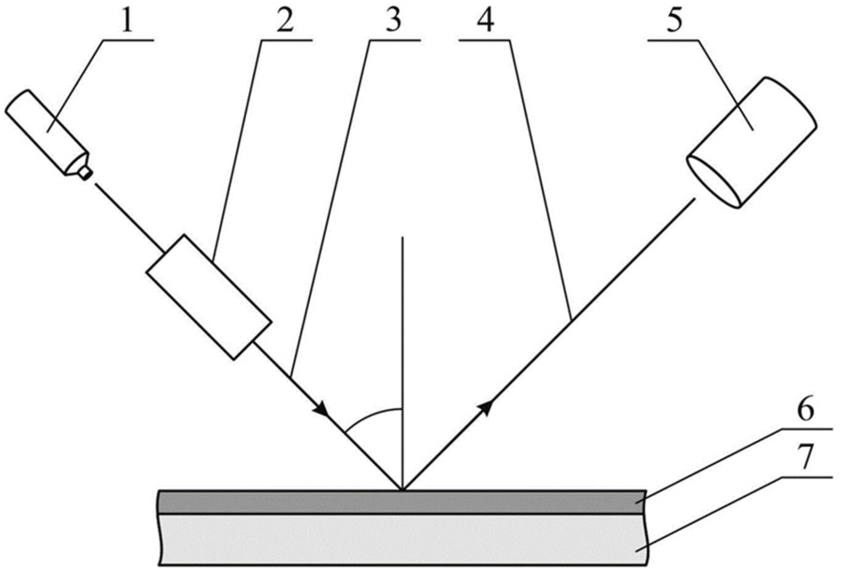
During the experiments, the following epilams were used: Aqualin, Efren-K, and Polisam-20, which have a maximum operating temperature of 450 °C and allow for short-term operation up to a temperature of 700 °C. Further in this article, epilams are arbitrarily designated as 1, 2, 3. The technology of applying epilams to the surface of bearing inserts consisted of the following: Experiments were carried out for a new set of inserts. Initially, their degreasing was carried out in ozone-safe freon-116 (C2F6) by volume immersion, followed by drying. After that, at ambient temperature, direct epilamization was carried out by immersing the inserts in the epilam. To determine the thickness of the epilam layer, which was adsorbed on the surface of the bearing insert, and the thickness of the oil boundary lubricating layer, which was formed on the surface of the epilam, preliminary laboratory studies were conducted. As an analogue of the bearing insert surface, a polished metal surface was used, which was covered with a layer of epilam by volume immersion. The time of the metal surface being in the volume of the epilam varied in the range of 2–10 min, after which the surface was dried at a temperature of 20 °C. The thickness of the epilam layer, which was adsorbed on the metal surface, was determined on an ellipsometric installation; the principal scheme of this is shown in Figure 5.
Ellipsometry is one of the most common methods for determining the thickness of thin layers of liquids (transparent for optical study) by analyzing the angles of light reflection from a clean surface and from a surface with a coating [76].
The thickness of the epilam layer adsorbed on the metal surface, as well as the structural characteristics of the boundary lubricating layers (layer thickness and wetting angle), was determined using an ES01 spectroscopic ellipsometer (manufacturer Ellitop, Beijing, China). The ES01 ellipsometer is designed to measure the parameters of the layer structure (e.g., thickness) of single-layer and multilayer nanofilms, including their physical parameters (e.g., refractive index n, extinction coefficient k or dielectric functions ε1 and ε2). The ES01 ellipsometer allows you to measure the thickness of thin adsorbed nanofilms in the range of 3–100 nm, with an accuracy of 0.2 nm, and determine the wetting angles in the range of 2–60 degrees, with an accuracy of 0.1 degree. In addition, it allows you to determine the thickness of the liquid layer in the range of up to 22–25 μm with an accuracy of 0.2 μm. The change in the technical condition of bearing inserts in the case of applying an antifriction coating (epilam) to their surface was carried out for the marine diesel 12V32/40 MAN-Diesel&Turbo. These diesels are some of the most common models of the MAN-Diesel&Turbo company (Augsburg, Germany) and are used both in marine, and in railway transport, as well as in stationary power installations (as generators of electric stations) [77,78]. Two diesels 12V32/40 MAN-Diesel&Turbo were installed on a specialized marine vessel that was designed for container transportation. The diesels transmitted their power through a reducer to one screw according to the scheme, which is shown in Figure 6.
The diesels were operated at the same load, using the same types of fuel and oil [79,80,81]. When operating diesels outside of special environmental areas, the Sulfur Emission Control Areas (SECAs) [82,83], RMG380 fuel (TFG MARINE PTE LTD, Ocean Financial Centre, Singapore) with a sulfur content of 0.048% was used. When operating diesels in SECAs [84,85,86], DMA fuel with a sulfur content of 0.076% was used. Throughout the entire experiment, Castrol TLX PLUS 404 lubrication motor oil was used (Castrol, Pangbourne, UK).
The V-shaped layout of the diesel allowed the bearing inserts of one of the rows of diesel cylinders to be treated with an antifriction coating (epilam). At the same time, the bearing inserts of another row of cylinders were not treated with epilam. Thus, for each of the diesels, the bearing inserts of one row of cylinders (yellow and blue in Figure 6) were treated with epilam, while the inserts of another row of cylinders (grey in Figure 6) were not treated.
The final stage of the study was measuring the wear of the bearing shell surfaces, which was determined for each row of each diesel engine. For this purpose, Walcom LB3002 electronic scales (manufacturer Ellitop, China) were used, which allow measurements with a maximum weight of 3100 g and a resolution of 0.01 g.
Thus, the main methods used in the research were optical (which measured the thickness of the epilam layer adsorbed on the metal surface, as well as the thickness of the boundary lubricating layer and its edge wetting angles) and gravimetric (which determined the mass of the bearing liners before and after the experiment, as well as their wear).

4. Results

The research was conducted in a scientific laboratory (first and second stages) and on the diesel engines of a specialized marine vessel (third stage).
The first stage of the research involved determining the optimal time required to apply epilams to a metal surface, as well as selecting epilams that ensure the formation of boundary lubricating layers with the greatest thickness and contact angle of wetting.
Initially, the thickness of the epilam coating applied to the metal surface was determined using an ES01 ellipsometer. To improve accuracy, the thickness of the epilam layer adsorbed on the surface was measured five times for each time interval for each epilam. After that, the average value of the adsorbed thickness of the epilam layer was determined from all the obtained values. The values of the average thickness of the epilam layer, as well as the range of values obtained during the measurement, are given in Table 1.
For better visualization, the changes in the average thickness of the adsorbed epilam layer (as well as the deviation of the values from the average value) are shown in Figure 7.
As can be seen from the data provided (Table 1 and Figure 7), after 6–10 min of exposure to the solution, the thickness of the epilam adsorption layer on the metal surface stabilizes. In this case, the thickness of the epilam adsorption layer for different samples varies in the range h = 11.2–17.4 nm.
The objective of the second stage of the research was to determine the effect of epilams on the structural characteristics of boundary lubricating layers (layer thickness ds and contact angle θ). Castrol TLX PLUS 404 was chosen as the oil. This oil was used in the circulating lubrication system of the MAN-B&W 12V32/40 marine diesel engine. Using the ES01 ellipsometer, the characteristics of the boundary lubricating layer formed on a “clean” metal surface (without epilam coating) were initially determined. After that, the boundary layer thickness ds and contact angle θ were determined for the boundary lubricating layer formed on a surface with different epilam coatings. To ensure the required accuracy, these parameters were measured five times. After that, the obtained values were averaged.
The average values of the boundary layer thickness ds and the contact angle θ, as well as the range of their changes, are given in Table 2.
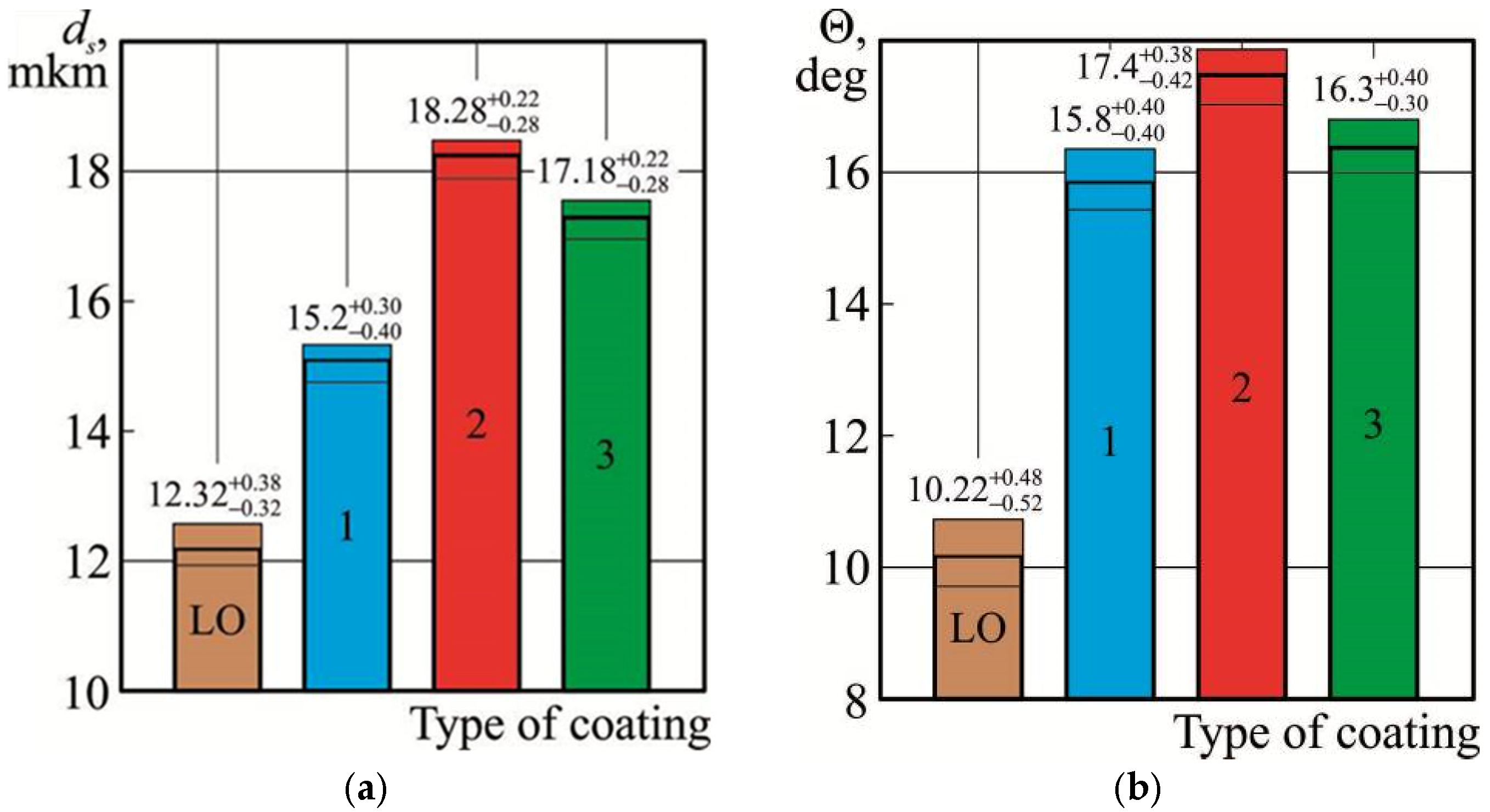
For better visualization, the change in the boundary layer thickness ds and the contact angle θ (as well as the deviation of the values from the average value) are shown in Figure 8.
Here, the designation LO (lubrication oil) refers to the direct thickness of the boundary oil layer ds, which forms on the metal surface, as well as the value of its wetting edge angles θ. Under the designations 1, 2, 3—the thickness of the boundary oil layer ds, which forms on the same surface when it is covered with a layer of epilam, as well as the values of the wetting edge angles θ.
As the results show, epilamination provides a 1.23 to 1.40 times increase in the thickness of the oil boundary layer (ds), as well as a 1.55 to 1.60 times increase in the edge wetting angle (θ).
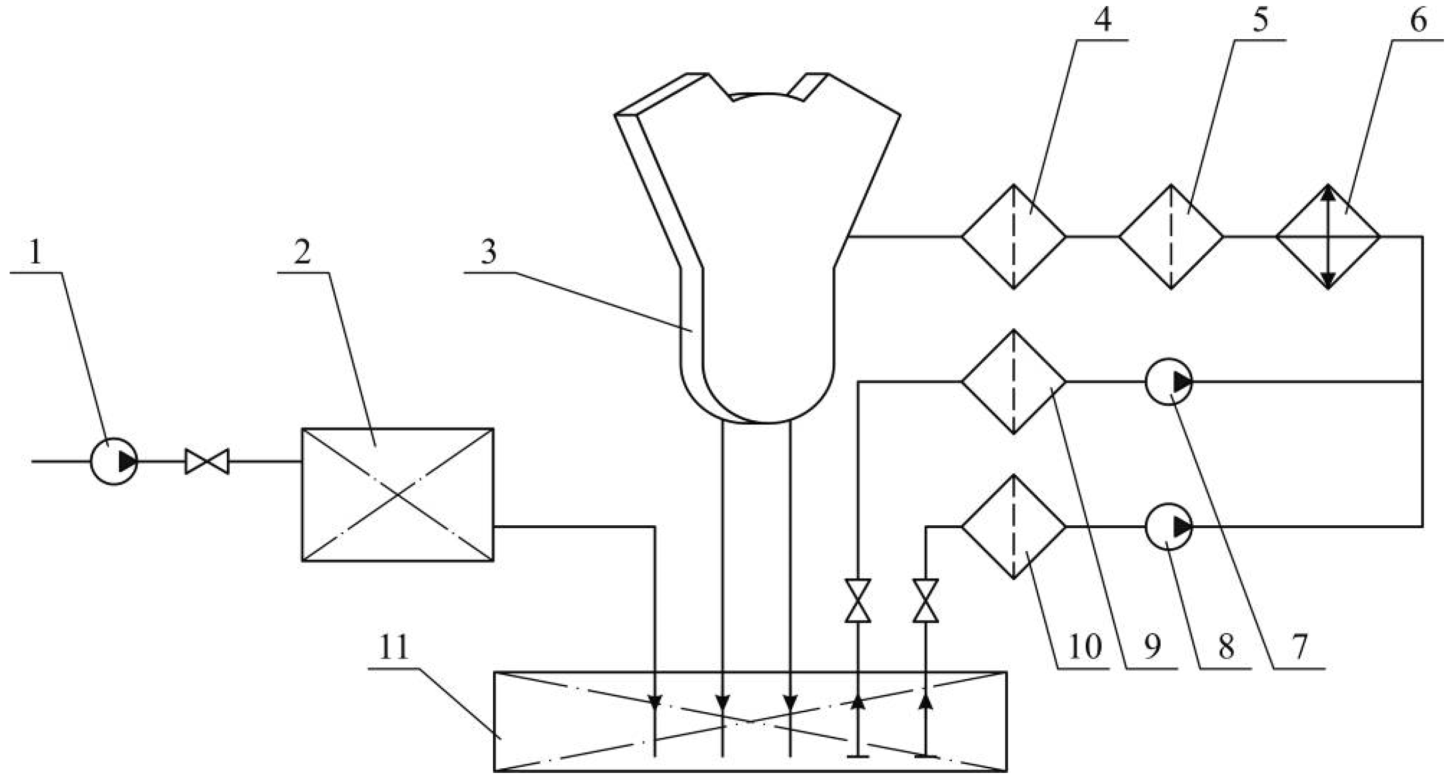
The third stage of research was carried out on 12V32/40 MAN-Diesel&Turbo marine diesel engines. The schematic diagram of the circulating lubrication system is shown in Figure 9.
The supply of lubricating oil to the circulation lubrication system is carried out by lubrication pump 1, which ensures the replenishment of lubrication tank 2 and the subsequent entry of the lubricant into the drain tank 11. The supply of lubricant for lubricating the parts of diesel engine 3 is provided by the circulation pumps 7 or 8, while the lubricant is subjected to preliminary cleaning in coarse filter 9 or 10. If necessary, the lubricant is cooled in cooler 6. Before entering the diesel engine, the lubricant is cleaned in the coarse filter 5 and fine filter 4.
Considering the results of the first and second stages of the research (results presented in Table 1 and Table 2 and Figure 7 and Figure 8), the third stage was conducted using epilams 2 and 3. These epilams ensure the formation of boundary layers with the greatest thickness and contact angles of wetting on the metal surface.
The operating time of the diesel engines (and, accordingly, the time of the research) was about 3200 h. During this time, the 12V32/40 MAN-Diesel&Turbo diesel engines operated in a wide range of loads—35–85% of the rated power. At the same time, all the necessary parameters were maintained in the cooling and lubrication systems, which prevented temperature overloads.
This stage of the research was carried out on 12V32/40 MAN-Diesel&Turbo marine engines. The bearing shells of one row of cylinders of the starboard engine were coated with epilam 2 (yellow row in Figure 6). The bearing shells of one row of cylinders of the port engine were coated with epilam 3 (blue row in Figure 6). Each engine had a row of cylinders with bearing shells that were not coated with epilam (grey row in Figure 6).
To determine the impact of antifriction coatings (epilams) on the technical condition of the bearing shells after the regulatory service life of the bearing units, the wear of their bearing surfaces was assessed. For this purpose, the wear of the bearing shells was determined. The condition of the bearing shells that were not coated with epilam is shown in Figure 10. The condition of the bearing shells that were coated with epilam is shown in Figure 11.
The initial visual inspection of the bearing liners revealed an improvement in the technical condition of the liners, which were previously coated with a layer of epilam. This fact was established for both the starboard diesel engines (for which epilam No. 2 was used) and the portside (for which epilam No. 3 was used).
Wear of the bearing shell surfaces (and, accordingly, the deterioration of their technical condition), which were pre-treated with epilam, was observed only in the central part. This was the part of the bearing shell that was the most loaded and exposed to contact with the diesel shaft compared to the others. In this regard, the wear of this section of the bearing shell was considered standard and, in the case of acceptable values, not critical. The wear of the shell surface, to which the epilam layer was not applied, spread over a larger area and was also deeper. This indicates that, in this case, stronger contact interactions occur between the surface of the bearing shell and the shaft. The reason for their occurrence is a decrease in the thickness of the boundary lubricant layer, as well as a decrease in the wetting angles. These are the signs that are characteristic in the absence of an adsorption layer of an antifriction coating (epilam) on the surface of the shell.
Thus, a visual inspection of the bearing shell condition was an additional (in addition to weight) research method. At the same time, it allowed us to perform a preliminary assessment of the effectiveness of applying the epilam coating, as well as make assumptions about the advantages of using one epilam over another.
The main objective of bearing shell condition analysis was to assess the efficiency of the lubrication system. In this case, there were conclusions made about the quality of the engine oil used, as well as the correctness of the selected lubrication, cooling, and diesel engine load modes [87,88].
One of the most accurate methods for determining changes in surface geometry is scanning them with an electron microscope. Unfortunately, the use of such measuring equipment directly on sea vessels is still difficult. This is due to both the cost of such measuring devices and the need for specialists on board who are able to perform measurements and analyze them. In addition, the frequency of using an electron microscope on board a sea vessel is extremely low. Sending liners or other diesel units to determine their wear using the electron scanning method is connected with additional costs (for example, for a 12V32/40 MAN-Diesel&Turbo diesel, it is necessary to analyze the condition of 24 bearing shells). In addition, sending diesel parts to a research laboratory, as well as receiving the research results, takes a certain amount of time. This delays the decision-making time and the efficiency of the diesel lubrication system.
In this regard, an assessment of the bearing shell surfaces was performed by measuring their wear. For this purpose, Walcom LB3002 electronic scales (manufacturer Ellitop, China) were used, which allow for measurements with a maximum weight of 3100 g and a resolution of 0.01 g. According to the operating instructions for marine diesel engines, the weight of the bearing shells was 2850 g, which fully met the conditions for using the Walcom LB3002 electronic scales.
The weight of the bearing shells of the 12V32/40 MAN-Diesel&Turbo diesel engine before their installation on the diesel engine and after the operational period was measured by weighing them once. In both cases, before weighing, the bearing shells were cleaned of all contaminants and treated with cetyl alcohol C16H33OH. The results of bearing mass measurements are given in Table 3 and Table 4.
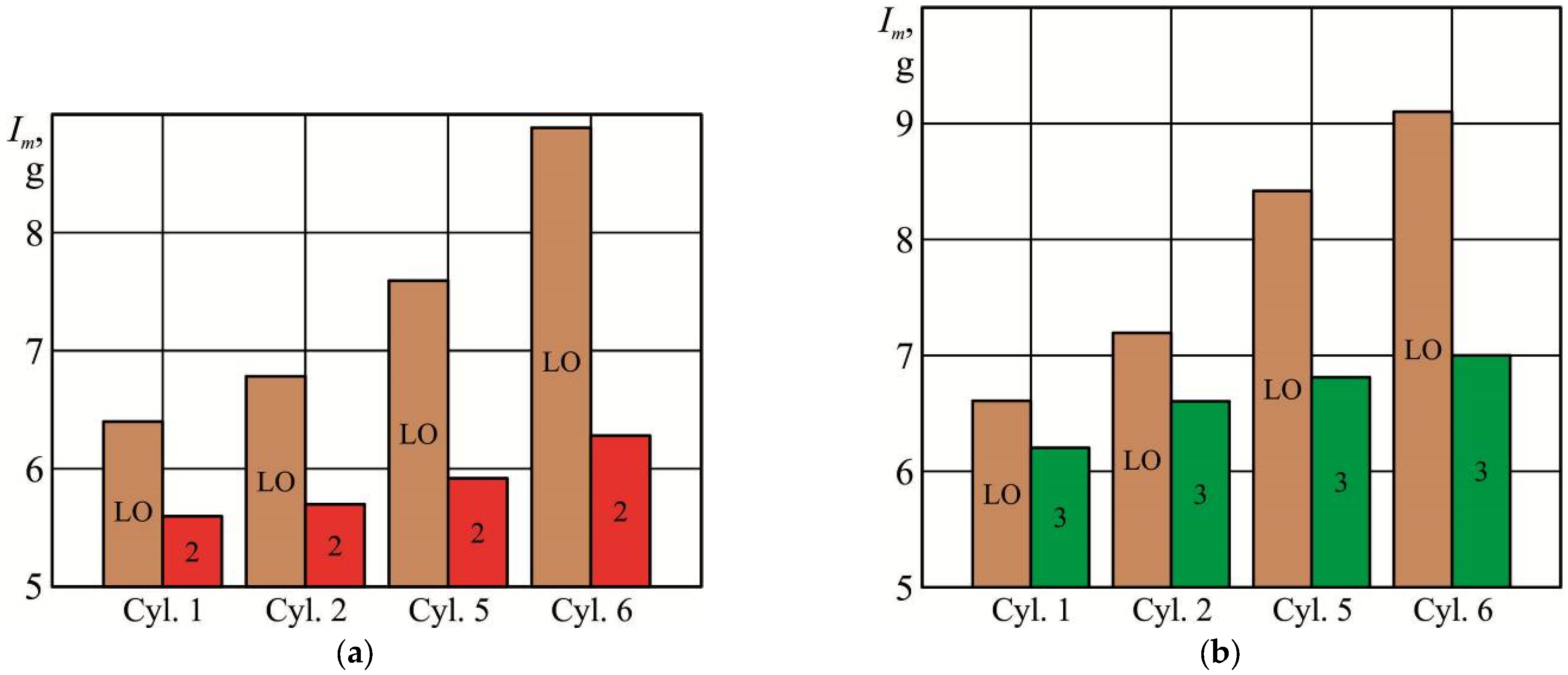
The wear of bearing liners (as an indicator by which the performance of the diesel lubrication system and the efficiency of using epilams were assessed) was determined as the difference in their mass before and after operation. The results of measuring the wear of bearing liners are given in Table 5.
Based on the results of Table 5, diagrams were made and are shown in Figure 12.
The percentage reduction in wear in the case of coating the bearing surfaces with various epilams can be estimated using the expression:
Δ I m i = I m W I m E I m W 100 % ,
where Δ I m i —the reduction in wear of the liner of the i-th bearing, %;
I m W ,   I m E —the wear of the liner of the i-th bearing without a surface coating and with a surface coating with a layer of epilam, g.
The values obtained in accordance with the expression (1) for different operating conditions of the 12V32/40 MAN-Diesel&Turbo diesel engine are given in Table 6.
Based on the results of Table 6, diagrams were made that reflect the percentage reduction in wear of bearing liners in the case of covering their surface with a layer of epilam (Figure 13).
Considering the uneven load on the different cylinders of the diesel engine, the technical condition of the bearing assemblies differs from each other [89,90]. This is particularly manifested in the unequal wear of the bearing inserts [91,92]. In this case, the bearing inserts of the cylinders located closer to the load consumer (propeller or electric generator) have greater wear compared to the inserts that are further away from the load consumer.
When conducting experiments, the wear of the liner for the “stern” bearing (for cylinder No. 6) was taken as 1; the wear of other liners was recalculated according to this value in relative units. The calculation results are given in Table 7 and Figure 14.
Based on the results of Table 7, diagrams were made and shown in Figure 14.
It should be noted that the results of determining the wear of the bearing inserts in different diesel engines (portsaid and starboard) in the case of applying epilams 2 and 3 to their surface, as well as when operating bearing inserts without applying antifriction coatings to their surface, have proportional values. This confirms the correctness of the theoretical assumptions and the accuracy of the measurements.
The method of epilamination, applied to ship bearings, has not received widespread distribution in the components of ship technical systems. This is, among other things, associated with the conservatism of marine power engineering as a science and the desire of the ship’s crew to avoid additional risks arising from the introduction of innovative ideas. This especially applies to such responsible nodes as ship diesels. However, with high-quality preliminary research, as well as compliance with the technology of applying epilams to surfaces, it is possible to create conditions that contribute to improving their operational characteristics and technical condition.

5. Discussion

Plain bearing liners are among the most critical components of marine diesel engines and ensure the transfer of the reciprocating motion of the piston in the cylinder into the rotational motion of the crankshaft. Their operation is impossible without the use of a lubricant (motor oil), which creates a lubricating layer and prevents the direct contact of surfaces. The deterioration of the technical condition of the bearing liners can lead to increased mechanical and thermal loads. This, in turn, increases power losses due to friction and reduces the effective power of the diesel engine. Improving the technical condition of the bearing liners is possible by a preliminary (before operation) treatment with antifriction coatings. Such coatings include epilams, which are polymer fluorine-containing substances that are applied to metal surfaces. After application to a metal surface, epilams form a thin film several tens of nm thick. However, this film subsequently promotes the formation of more structured boundary layers of lubricant (motor oil) on its surface. The complex of these interactions helps reduce wear on the surface of the bearing liners. It is possible to apply epilams to a metal surface using freons.
The application time of epilams is characterized by the saturation limit, exceeding which does not increase the thickness of the layer adsorbed on the surface. For epilams Aqualin, Efren-K, and Polisam-20, which were used in the experiment, the highest intensity of adsorbed film formation corresponded to the initial stage of application. In this case, during the first 2–4 min of application, a film was formed, the thickness of which was 74–88% of the total thickness of the epilam layer adsorbed during the entire period of application. Over a period of 8–10 min, the intensity of the increase in the thickness of the adsorbed layer decreases. An application time of epilam above 10 min has virtually no effect on the thickness of the adsorbed layer.
An increase in the long-range surface forces (which is facilitated by the application of epilam) increases the structural ordering of the boundary layer of oil formed on the metal surface. In this case, the thickness of the oil layer on the surface of the bearing shell. At the same time, the elastic damping properties of the oil increase, which is one of the reasons for reducing the wear of the contact surfaces. It has been experimentally confirmed that this epilamination of bearing liners contributes to a 1.23–1.48-fold increase in the thickness of the boundary layer and a 1.55–1.70-fold increase in the wetting angles, which further contributes to a proportional reduction in the wear of the bearing liners and an improvement in their technical condition.

6. Conclusions

The scientific novelty of the research was an experimentally confirmed fact about the possibility of maintaining the technical condition of the surfaces of marine diesel engines bearing liners due to their preliminary treatment with antifriction coatings (epils). At the same time, the optimal time for epilam application on the metal surface of the bearing liners was established and the effect of epilams on their wear was determined.
All research was carried out on power plants that have valid certificates of classification societies (in particular, the international register of Lloyd’s Register of Shipping, England; American Bureau of Shipping, ABS, USA). During the experiments, the operation of ships, diesels, and the systems ensuring their functioning was carried out in accordance with the requirements of the International Convention SOLAS, the International Convention MARPOL, as well as operating instructions.
The conducted research and the results obtained allow us to draw the following conclusions:
  • For the bearing inserts of marine diesel engines, epilamination of their surfaces can be used as a method that contributes to the reduction in contact loads.
  • The thickness of the epilam layer on the surface of the bearing inserts in marine diesel engines can reach 11.2–17.4 nm, and the time required for its adsorption does not exceed 10 min.
  • The nanolayer of epilams, applied to the metal surface, leads to an increase in the structural characteristics of the oil boundary layer. This is expressed in the increase in the thickness and edge wetting angle parameters that contribute to the increase in the elastic damping properties of the oil and the wedging pressure in the tribological system of metal–oil layer–metal. In the research conducted, the increase in these parameters was as follows:
    • For the thickness of the oil boundary layer from 12.3 µm (in the case of operation without applying epilams) to 15.2–18.3 µm (when using various epilams);
    • for the edge wetting angle from 10.2 deg (in the case of operation without applying epilams) to 15.8–17.4 deg (when using various epilams).
  • Increasing the structural characteristics of the oil boundary layer by epilaminating the surfaces of the bearing inserts allow us to significantly reduce their wear. For the marine diesel engine 12V32/40 MAN-Diesel&Turbo, it was experimentally established that epilamination provided a 1.1–1.4 times reduction in the wear of the surface of the bearing inserts, as well as their better technical condition.
  • Epilamination belongs to the category of modern nanotechnological methods. This method requires preliminary research to determine the optimal types of antifriction coatings (epilams) and the time of their application to surfaces, without causing additional labor costs when using it while also increasing the energy efficiency of tribological systems.
  • One of the important characteristics of organic coatings (including epilams, which were used in the research) is their adhesive properties. Due to increased adhesion, epilams form a thin film on the metal surface, which increases long-range surface forces and contributes to an increase in the ordered structure of the boundary lubricating layer. As it works for any antifriction coating, the thickness of the adsorbed epilam layer decreases over time. At the same time, the adhesive forces that hold the epilam layer on the metal surface decrease proportionally. The study of the changes in the intensity of the adhesive forces, as well as the study of changes in the thickness of the epilam coating layer for different time intervals, will be the next stage of the research. The implementation of this task will allow for a diagnosis of the technical condition of marine diesel engines’ bearing liners, as well as the development of recommendations for improving the efficiency of their lubrication systems.

Author Contributions

Conceptualization, S.S. and A.S.; methodology, Y.Z.; software, O.F.; validation, V.P., P.K. and Y.Z.; formal analysis, S.S.; investigation, A.S.; resources, O.F.; data curation, O.F.; writing—original draft preparation, S.S. and A.S.; writing—review and editing, P.K.; visualization, S.S.; supervision, A.S.; project administration, Y.Z.; funding acquisition, V.P. All authors have read and agreed to the published version of the manuscript.

Funding

This publication was supported by the project “Innovative Technologies for Smart Low Emission Mobilities”, funded as project No. CZ.02.01.01/00/23_020/0008528 by Programme Johannes Amos Comenius, call Intersectoral cooperation.

Data Availability Statement

The raw data supporting the conclusions of this article will be made available by the authors on request.

Acknowledgments

The authors thank Brno University of Technology for support.

Conflicts of Interest

The authors declare no conflict of interest.

Abbreviations

SECAsSulfur Emission Control Areas
DMADistillate Marine Fuel A
ABSAmerican Bureau of Shipping

References

  1. Sagin, S.V.; Karianskyi, S.; Sagin, S.S.; Volkov, O.; Zablotskyi, Y.; Fomin, O.; Píštěk, V.; Kučera, P. Ensuring the safety of maritime transportation of drilling fluids by platform supply-class vessel. Appl. Ocean Res. 2023, 140, 103745. [Google Scholar] [CrossRef]
  2. Vrzala, M.; Gŏno, M.; Gŏno, R.; Kotulla, M.; Wzorek, M.; Leonowicz, Z. Distributed Generation Power Systems in Wastewater Management. Energies 2022, 15, 6283. [Google Scholar] [CrossRef]
  3. Lu, Y.; Gu, Z.; Liu, S.; Wu, C.; Shao, W.; Li, C. Research on Main Engine Power of Transport Ship with Different Bows in Ice Area According to EEDI Regulation. J. Mar. Sci. Eng. 2021, 9, 1241. [Google Scholar] [CrossRef]
  4. Melnyk, O.; Onyshchenko, S.; Onishchenko, O.; Shcherbina, O.; Vasalatii, N. Simulation-based method for predicting changes in the ship’s seaworthy condition under impact of various factors. Stud. Syst. Decis. Control 2023, 481, 653–664. [Google Scholar] [CrossRef]
  5. Budashko, V.; Shevchenko, V. The Synthesis Of Control System To Synchronize Ship Generator Assemblies. East. Eur. J. Enterp. Technol. 2021, 1, 45–63. [Google Scholar] [CrossRef]
  6. Varbanets, R.; Shumylo, O.; Marchenko, A.; Minchev, D.; Kyrnats, V.; Zalozh, V.; Aleksandrovska, N.; Brusnyk, R.; Volovyk, K. Concept of vibroacoustic diagnostics of the fuel injection and electronic cylinder lubrication systems of marine diesel engines. Pol. Marit. Res. 2022, 29, 88–96. [Google Scholar] [CrossRef]
  7. Sagin, S.V.; Semenov, O.V. Marine slow-speed diesel engine diagnosis with view to cylinder oil specification. Am. J. Appl. Sci. 2016, 13, 618–627. [Google Scholar] [CrossRef]
  8. Ye, W.; Niu, M.; Bian, L.; Duan, C.; Gao, C.; Zhang, P.; Zhang, Y.; Zhang, S. Construction of High-Load-Bearing Capacity Polyamide-Imide Self-Lubricating Coatings with Various Nanoparticles Through Worn Surface of Cobblestone-like Road. Coatings 2025, 15, 338. [Google Scholar] [CrossRef]
  9. Dong, J.; Wen, H.; Zhu, J.; Guo, J.; Zong, C. Analysis of Thermo-Hydrodynamic Lubrication of Three-Lobe Semi-Floating Ring Bearing Considering Temperature–Viscosity Effect and Static Pressure Flow. Lubricants 2024, 12, 140. [Google Scholar] [CrossRef]
  10. Jia, D.; Li, C.; Deng, W.; Ji, H.; Hao, L. Effects of Hyperelliptic Bearings Bush on Connecting Rod Big-End Lubrication and Design Optimization. Lubricants 2023, 11, 293. [Google Scholar] [CrossRef]
  11. Sagin, S.; Madey, V.; Sagin, A.; Stoliaryk, T.; Fomin, O.; Kučera, P. Ensuring Reliable and Safe Operation of Trunk Diesel Engines of Marine Transport Vessels. J. Mar. Sci. Eng. 2022, 10, 1373. [Google Scholar] [CrossRef]
  12. Popovskii, Y.M.; Sagin, S.V.; Khanmamedov, S.A.; Grebenyuk, M.N.; Teregerya, V.V. Designing, calculation, testing and reliability of machines: Influence of anisotropic fluids on the operation of frictional components. Russ. Eng. Res. 1996, 16, 1–7. [Google Scholar]
  13. Likhanov, V.A.; Lopatin, O.P. Dynamics of soot formation and burnout in a gas diesel cylinder. IOP Conf. Ser. Mater. Sci. Eng. 2020, 862, 062033. [Google Scholar] [CrossRef]
  14. Onyshchenko, S.; Shibaev, O.; Melnyk, O. Assessment of potential negative impact of the system of factors on the ship’s operational condition during transportation of oversized and heavy cargoes. Trans. Mar. Sci. 2021, 10, 126–134. [Google Scholar] [CrossRef]
  15. Budashko, V. Thrusters physical model formalization with regard to situational and identification factors of motion modes. Int. J. Energy Environ. 2020, 14, 5–8. [Google Scholar] [CrossRef]
  16. Mičietová, A.; Neslušan, M.; Florková, Z.; Čilliková, M. Analysis of the coating delamination after laser beam cutting. Manuf. Technol. 2023, 23, 670–675. [Google Scholar] [CrossRef]
  17. Mardonov, U.; Khasanov, S.; Jeltukhin, A.; Ozodova, S. Influence of using cutting fluid under the effect of static magnetic field on chip formation in metal cutting with HSS tools (turning operation). Manuf. Technol. 2023, 23, 73–80. [Google Scholar] [CrossRef]
  18. Wang, X.; Xu, Z.; Lu, H.; Tan, Y.; Xu, X.; Wu, H. Preparation and Tribology of Textured Ti-6Al-4V with Thermal Oxide Coating. Coatings 2025, 15, 258. [Google Scholar] [CrossRef]
  19. Zablotsky, Y.V.; Sagin, S.V. Maintaining Boundary and Hydrodynamic Lubrication Modes in Operating High-pressure Fuel Injection Pumps of Marine Diesel Engines. Indian J. Sci. Technol. 2016, 9, 208–216. [Google Scholar] [CrossRef]
  20. Madey, V.V. Usage of biodiesel in marine diesel engines. Austrian J. Tech. Nat. Sci. 2021, 7–8, 18–21. [Google Scholar] [CrossRef]
  21. Sagin, S.V.; Sagin, S.S.; Fomin, O.; Gaichenia, O.; Zablotskyi, Y.; Píštěk, V.; Kučera, P. Use of biofuels in marine diesel engines for sustainable and safe maritime transport. Renew. Energy 2024, 224, 120221. [Google Scholar] [CrossRef]
  22. Sramhauser, K.; Naprstkova, N.; Hren, I.; Spalek, F.; Vlach, T.; Kunes, R.; Tupy, O. Wear analysis of indexable inserts after machining of austenitic steel 1.4404. Manuf. Technol. 2023, 23, 917–926. [Google Scholar] [CrossRef]
  23. Sagin, S.V.; Semenov, O.V. Motor oil viscosity stratification in friction units of marine diesel motors. Am. J. Appl. Sci. 2016, 13, 200–208. [Google Scholar] [CrossRef]
  24. Moon, S.; Park, S.; Son, J.; Oh, K.; Jang, S. Simplified Modeling and Analysis of Surface Temperature Distribution in Electrically Heated Catalyst for Diesel Urea-SCR Systems. Energies 2022, 15, 6406. [Google Scholar] [CrossRef]
  25. Borko, T.; Bilic, G.; Žbulj, K.; Otmacic Curkovic, H. Individual and ’Joint Effect of Oleic Acid Imidazoline and CeCl3 on Carbon Steel Corrosion in CO2-Saturated Brine Solution. Coatings 2025, 15, 93. [Google Scholar] [CrossRef]
  26. Zhang, Z.; Ni, N.; Xu, Y. Effects of Different Polyols with Functions on the Properties of Polyester Polyol-Based Polyurethane Coatings. Coatings 2025, 15, 61. [Google Scholar] [CrossRef]
  27. Melnyk, O.; Onishchenko, O.; Onyshchenko, S.; Voloshyn, A.; Kalinichenko, Y.; Rossomakha, O.; Naleva, G.; Rossomakha, O. Autonomous ships concept and mathematical models application in their steering process control. TransNav 2022, 16, 553–559. [Google Scholar] [CrossRef]
  28. Khan, A.A.; Minai, A.F.; Pachauri, R.K.; Malik, H. Optimal Sizing, Control, and Management Strategies for Hybrid Renewable Energy Systems: A Comprehensive Review. Energies 2022, 15, 6249. [Google Scholar] [CrossRef]
  29. Vladov, S.; Scislo, L.; Sokurenko, V.; Muzychuk, O.; Vysotska, V.; Sachenko, A.; Yurko, A. Helicopter Turboshaft Engines’ Gas Generator Rotor R.P.M. Neuro-Fuzzy Onboard Controller Development. Energies 2024, 17, 4033. [Google Scholar] [CrossRef]
  30. Vladov, S.; Shmelov, Y.; Yakovliev, R.; Stushchankyi, Y.; Havryliuk, Y. Neural Network Method for Controlling the Helicopters Turboshaft Engines Free Turbine Speed at Flight Modes. CEUR Workshop Proc. 2023, 3426, 89–108. Available online: https://ceur-ws.org/Vol-3426/paper8.pdf (accessed on 14 February 2025).
  31. Bricín, D.; Špirit, Z.; Gilík, H.; Kaufman, J. Effect of laser shock peening on the microstructure of P265GH steel and X6CrNiTi18-10 stainless steel dissimilar welds. Manuf. Technol. 2024, 24, 9–14. [Google Scholar] [CrossRef]
  32. Tong, X.; Wang, S. Analysis of wear vibration behavior of micro-textured coated cemented carbide considering high-order scale. Coatings 2024, 14, 791. [Google Scholar] [CrossRef]
  33. Nothnagel, R.M.; Boidi, G.; Franz, R.; Frauscher, M. Assessing the potential of bio-based friction modifiers for food-grade lubrication. Lubricants 2024, 12, 247. [Google Scholar] [CrossRef]
  34. Zheng, J.; Zhao, Y.; Li, J.; Zhang, S.; Zhang, J.; Sun, D. Study on microstructure and tribological mechanism of Mo incorporated (AlCrTiZr)N high-entropy ceramics coatings prepared by magnetron sputtering. Nanomaterials 2024, 14, 814. [Google Scholar] [CrossRef]
  35. Chen, S.; He, S.; Zhao, G.; Chen, G.; Xu, Y. Enhancing machinability and sustainability: The effects of hybrid MQL+CO2 cooling on the drilling of AA7075T6 with TiO2 and C-reinforced composites. Machines 2024, 12, 449. [Google Scholar] [CrossRef]
  36. Sagin, S.V.; Solodovnikov, V.G. Cavitation Treatment of High-Viscosity Marine Fuels for Medium-Speed Diesel Engines. Mod. Appl. Sci. 2015, 9, 269–278. [Google Scholar] [CrossRef]
  37. Chybowski, L. Study of the Relationship between the Level of Lubricating Oil Contamination with Distillation Fuel and the Risk of Explosion in the Crankcase of a Marine Trunk Type Engine. Energies 2023, 16, 683. [Google Scholar] [CrossRef]
  38. Yang, P.; Li, P.; Yuan, Q.; Sun, Q.; Xing, Z.; Zhao, Z. Impact of Surface Grinding on the Performance of Tilting Pad Bearings. Coatings 2025, 15, 5. [Google Scholar] [CrossRef]
  39. Chybowski, L.; Szczepanek, M.; Gawdzi’nska, K.; Klyus, O. Particles Morphology of Mechanically Generated Oil Mist Mixtures of SAE 40 Grade Lubricating Oil with Diesel Oil in the Context of Explosion Risk in the Crankcase of a Marine Engine. Energies 2023, 16, 3915. [Google Scholar] [CrossRef]
  40. Melnyk, O.M.; Onishchenko, O.A.; Shyshkin, O.V.; Volkov, O.M.; Volyanskyy, S.M.; Maulevych, V.O.; Kreitser, K.O. Enhancing shipboard technical facility performance through the utilization of low-sulfur marine fuel grades. J. Chem. Technol. 2024, 32, 233–245. [Google Scholar] [CrossRef]
  41. Sagin, S.V.; Kuropyatnyk, O.A.; Zablotskyi, Y.V.; Gaichenia, O.V. Supplying of Marine Diesel Engine Ecological Parameters. Int. J. Marit. Sci. Technol. 2022, 69, 53–61. [Google Scholar] [CrossRef]
  42. Zablotsky, Y.V.; Sagin, S.V. Enhancing Fuel Efficiency and Environmental Specifications of a Marine Diesel When using Fuel Additives. Indian J. Sci. Technol. 2016, 9, 353–362. [Google Scholar] [CrossRef]
  43. Petrychenko, O.; Levinskyi, M.; Goolak, S.; Lukoševicius, V. Prospects of Solar Energy in the Context of Greening Maritime Transport. Sustainability 2025, 17, 2141. [Google Scholar] [CrossRef]
  44. Chybowski, L.; Kowalak, P.; Dabrowski, P. Assessment of the Impact of Lubricating Oil Contamination by Biodiesel on Trunk Piston Engine Reliability. Energies 2023, 16, 5056. [Google Scholar] [CrossRef]
  45. Ouyang, H.; Li, W.; Gao, F.; Huang, K.; Xiao, P. Research on Fault Diagnosis of Ship Diesel Generator System Based on IVY-RF. Energies 2024, 17, 5799. [Google Scholar] [CrossRef]
  46. Zhang, H.; Liu, X.; Gong, J.; Bai, S.; Sun, K.; Jia, H. Thermohydrodynamic Lubrication Characteristics of Piston Rings in Diesel Engine Considering Transient Heat Transfer under the Parameterized Surface Texture of Cylinder Liners. Energies 2023, 16, 7924. [Google Scholar] [CrossRef]
  47. Tongyang, L.; Xuan, M.; Xiqun, L.; Chuanjuan, W. Lubrication analysis for the piston ring of a two-stroke marine diesel engine taking account of the oil supply. Int. J. Engine Res. 2021, 22, 949–962. [Google Scholar] [CrossRef]
  48. Chenwei, M.; Zhiwei, G.; Chengqing, Y. Tribological behavior of co-textured cylinder liner-piston ring during running-in. Friction 2022, 10, 878–890. [Google Scholar] [CrossRef]
  49. Sumardiyanto, D.; Susilowati, S. Analysis the Occurrence of Wear on Crank Pin Bearing in Diesel Engine. J. Mech. Eng. Autom. 2021, 10, 19–23. [Google Scholar]
  50. Lijesh, K.; Khonsari, M. On the degradation of tribo-components in boundary and mixed lubrication regimes. Tribol. Lett. 2019, 67, 12. [Google Scholar] [CrossRef]
  51. Wolak, A.; Molenda, J.; Fijorek, K.; Łankiewicz, B. Prediction of the Total Base Number (TBN) of Engine Oil by Means of FTIR Spectroscopy. Energies 2022, 15, 2809. [Google Scholar] [CrossRef]
  52. Zaher, A.; Lgaz, H.; Boukhraz, A.; Aldalbahi, A.; Lee, H.-S.; Bourkhiss, B.; Ouhssine, M. Bio-Based Corrosion Inhibition of Carbon Steel Using Ammi visnaga L. Essential Oil in Acidic Mediums: Experimental Analysis and Molecular Modeling. Coatings 2024, 14, 1556. [Google Scholar] [CrossRef]
  53. Nelyubov, D.V.; Fakhrutdinov, M.I.; Sarkisyan, A.A.; Sharin, E.A.; Ershov, M.A.; Makhova, U.A.; Makhmudova, A.E.; Klimov, N.A.; Rogova, M.Y.; Savelenko, V.D.; et al. New Prospects of Waste Involvement in Marine Fuel Oil: Evolution of Composition and Requirements for Fuel with Sulfur Content up to 0.5%. J. Mar. Sci. Eng. 2023, 11, 1460. [Google Scholar] [CrossRef]
  54. Zjakić, I.; Galić, E.; Ljevak, I.; Matijević, M. Improving Prediction Model for Colorimetric Changes Due to Coating Processes with Oil-Based and UV Coatings. Coatings 2024, 14, 1488. [Google Scholar] [CrossRef]
  55. Liu, S.; Lv, J.; Liu, C. The effect of lubricant’s viscosity on reducing the frictional-induced fluctuation on the onset of friction. Lubricants 2024, 12, 136. [Google Scholar] [CrossRef]
  56. Krafka, M.; Lemberk, L.; Petkov, N.; Svobodová, L.; Bakalova, T. Comparison of mechanical and tribological properties of TiN and ZrN coatings deposited by Arc-PVD. Manuf. Technol. 2023, 23, 194–203. [Google Scholar] [CrossRef]
  57. Li, Q.; Cai, X.; Li, W.; Tan, Z.; Yang, C. Progress and prospect of ultrasonic vibratory cutting research. Manuf. Technol. 2023, 23, 638–648. [Google Scholar] [CrossRef]
  58. Ershov, M.A.; Savelenko, V.D.; Makhova, U.A.; Kapustin, V.M.; Abdellatief, T.M.M.; Karpov, N.V.; Dutlov, E.V.; Borisanov, D.V. Perspective towards a gasoline-property-first approach exhibiting octane hyperboosting based on isoolefinic hydrocarbons. Fuel 2022, 321, 124016. [Google Scholar] [CrossRef]
  59. Wang, X.; Zhang, W.; Lin, Z.; Li, H.; Zhang, Y.; Quan, W.; Chen, Z.; You, X.; Zeng, Y.; Wang, G.; et al. Current Status of Image Recognition Technology in the Field of Corrosion Protection Applications. Coatings 2024, 14, 1051. [Google Scholar] [CrossRef]
  60. Saciotto, V.; He, Q.; Guimaraes, M.C.; Depaiva, J.M.; Kohlscheen, J.; Fontana, L.C.; Veldhuis, S.C. A comparative study on Al0.6Ti0.4N coatings deposited by cathodic arc and HiPIMS in end milling of stainless steel 316L. Coatings 2024, 14, 811. [Google Scholar] [CrossRef]
  61. Sun, Q.; Zheng, D. Experimental analysis and wear prediction model based on friction heat for dry sliding contact. Coatings 2024, 14, 742. [Google Scholar] [CrossRef]
  62. Drímalová, P.; Nový, F.; Uhričík, M.; Váňová, P.; Šikyňa, L.; Chvalníková, V.; Slezák, M. Effect of change in current density on hydrogen embrittlement of advanced high-strength steel S960MC during hydrogenation. Manuf. Technol. 2024, 24, 40–47. [Google Scholar] [CrossRef]
  63. Zawada-Michałowska, M.; Pieśko, P.; Legutko, S. Effect of the cutting tool on the quality of a machined composite part. Manuf. Technol. 2023, 23, 870–879. [Google Scholar] [CrossRef]
  64. Lince, J.R.; Woods, P.; Woods, E.; Mak, W.H.; Sitzman, S.D.; Clough, A.J. Cold Spray Deposition of MoS2- and WS2-Based Solid Lubricant Coatings. Lubricants 2024, 12, 237. [Google Scholar] [CrossRef]
  65. Zhou, Y.; Zhao, R.; Geng, H.; Ren, B.; Liu, Z.; Liu, J.; Jiang, A.; Zhang, B. Effect of Cooling Method on Microstructure and Microhardness of CuCrFeMnNi High-Entropy Alloy. Coatings 2024, 14, 831. [Google Scholar] [CrossRef]
  66. Kaminski, P. Experimental Investigation into the Effects of Fuel Dilution on the Change in Chemical Properties of Lubricating Oil Used in Fuel Injection Pump of Pielstick PA4V185 Marine Diesel Engine. Lubricants 2022, 10, 162. [Google Scholar] [CrossRef]
  67. Ormond, N.; Kamel, D.; Lima, S.; Saha, B. Production of Sustainable Liquid Fuels. Energies 2024, 17, 3506. [Google Scholar] [CrossRef]
  68. Fotovvati, B.; Dehghanghadikolaei, A.; Namdari, N. Laser-Assisted coating techniques and surface modifications: A short review. Part. Sci. Technol. 2021, 39, 738–747. [Google Scholar] [CrossRef]
  69. Lyashenko, I.A.; Pham, T.H.; Popov, V.L. Controlling the friction coefficient and adhesive properties of a contact by varying the indenter geometry. Processes 2024, 12, 1209. [Google Scholar] [CrossRef]
  70. Haponova, O.; Tarelnyk, V.; Mościcki, T.; Tarelnyk, N.; Półrolniczak, J.; Myslyvchenko, O.; Adamczyk-Cieślak, B.; Sulej-Chojnacka, J. Investigation of the structure and properties of MoS2 coatings obtained by electrospark alloying. Coatings 2024, 14, 563. [Google Scholar] [CrossRef]
  71. Chybowski, L.; Szczepanek, M.; Sztangierski, R.; Brożek, P. Modeling of Selected Parameters of Used Lubricating Oil Diluted with Diesel Oil Using the Characteristics of Fresh Lubricating oil. Energies 2024, 17, 2047. [Google Scholar] [CrossRef]
  72. Wang, X.; Fan, C.; Sun, L.; Shang, H.; Zhang, D.; Xu, N.; Wang, B.; Xu, J. Performance of a Composite Inhibitor on Mild Steel in NaCl Solution: Imidazoline, Sodium Molybdate, and Sodium Dodecylbenzenesulfonate. Coatings 2024, 14, 652. [Google Scholar] [CrossRef]
  73. Zhang, W.; Xia, W.; Chen, Z.; Zhang, G.; Qian, S.; Lin, Z. Comparison of the Cathodic Protection of Epoxy Resin Coating/Zinc-Rich Coatings on Defective Areas under Atmospheric and Immersion Conditions: The Secondary Activation of Zinc Particles. Coatings 2024, 14, 336. [Google Scholar] [CrossRef]
  74. Al Sulaimi, R.; Eskandari, M.; Shirani, A.; Macknojia, A.Z.; Miller, W.; Berman, D. Effect of Cu and Ni Inclusion on Tribological Performance of Tribocatalytically Active Coatings in Hydrocarbon Environments. Coatings 2024, 14, 61. [Google Scholar] [CrossRef]
  75. Qiao, L.; Zhou, B.; Li, R.; Li, T.; Zhao, Y.; Zhang, X.; Lee, C.-H. Effects of Sliding Speed on Wear Behavior of High-Velocity Oxygen Fuel-Sprayed FeCrMoNiCuBSiC Metallic Glass Coatings. Lubricants 2025, 13, 10. [Google Scholar] [CrossRef]
  76. Sagin, S.V.; Solodovnikov, V.G. Estimation of Operational Properties of Lubricant Coolant Liquids by Optical Methods. Int. J. Appl. Eng. Res. 2017, 12, 8380–8391. [Google Scholar]
  77. Ershov, M.A.; Grigorieva, E.V.; Abdellatief, T.M.M.; Chernysheva, E.A.; Makhin, D.Y.; Kapustin, V.M. A New Approach for Producing Mid-Ethanol Fuels E30 Based on Low-Octane Hydrocarbon Surrogate Blends. Fuel Process. Technol. 2021, 213, 106688. [Google Scholar] [CrossRef]
  78. Onyshchenko, S.; Melnyk, O. Probabilistic assessment method of hydrometeorological conditions and their impact on the efficiency of ship operation. J. Eng. Sci. Technol. Rev. 2021, 14, 132–136. [Google Scholar] [CrossRef]
  79. Skoko, I.; Stanivuk, T.; Franic, B.; Bozic, D. Comparative Analysis of CO2 Emissions, Fuel Consumption, and Fuel Costs of Diesel and Hybrid Dredger Ship Engines. J. Mar. Sci. Eng. 2024, 12, 999. [Google Scholar] [CrossRef]
  80. Ershov, M.A.; Savelenko, V.D.; Makhmudova, A.E.; Rekhletskaya, E.S.; Makhova, U.A.; Kapustin, V.M.; Mukhina, D.Y.; Abdellatief, T.M.M. Technological Potential Analysis and Vacant Technology Forecasting in Properties and Composition of Low-Sulfur Marine Fuel Oil (VLSFO and ULSFO) Bunkered in Key World Ports. J. Mar. Sci. Eng. 2022, 10, 1828. [Google Scholar] [CrossRef]
  81. Budashko, V.; Shevchenko, V. Solving a task of coordinated control over a ship automated electric power system under a changing load. East. Eur. J. Enterp. Technol. 2021, 2, 54–70. [Google Scholar] [CrossRef]
  82. Volyanskaya, Y.; Volyanskiy, S.; Onishchenko, O.; Nykul, S. Analysis of possibilities for improving energy indicators of induction electric motors for propulsion complexes of autonomous floating vehicles. East. Eur. J. Enterp. Technol. 2018, 2, 25–32. [Google Scholar] [CrossRef]
  83. Sagin, S.V.; Kuropyatnyk, O.A. The Use of Exhaust Gas Recirculation for Ensuring the Environmental Performance of Marine Diesel Engines. Int. J. Marit. Sci. Technol. 2018, 65, 78–86. [Google Scholar] [CrossRef]
  84. Madey, V. Assessment of the efficiency of biofuel use in the operation of marine diesel engines. Technol. Audit. Prod. Reserves 2022, 2, 34–41. [Google Scholar] [CrossRef]
  85. Zhang, Y.; Zhong, Y.; Wang, J.; Tan, D.; Zhang, Z.; Yang, D. Effects of Different Biodiesel-Diesel Blend Fuel on Combustion and Emission Characteristics of a Diesel Engine. Processes 2021, 9, 1984. [Google Scholar] [CrossRef]
  86. Chybowski, L. The Initial Boiling Point of Lubricating Oil as an Indicator for the Assessment of the Possible Contamination of Lubricating Oil with Diesel Oil. Energies 2022, 15, 7927. [Google Scholar] [CrossRef]
  87. Sagin, S.; Karianskyi, S.; Madey, V.; Sagin, A.; Stoliaryk, T.; Tkachenko, I. Impact of Biofuel on the Environmental and Economic Performance of Marine Diesel Engines. J. Mar. Sci. Eng. 2023, 11, 120. [Google Scholar] [CrossRef]
  88. Vladov, S.; Shmelov, Y.; Yakovliev, R. Optimization of Helicopters Aircraft Engine Working Process Using Neural Networks Technologies. CEUR Workshop Proc. 2022, 3171, 1639–1656. Available online: https://ceur-ws.org/Vol-3171/paper117.pdf (accessed on 14 February 2025).
  89. Neumann, S.; Varbanets, R.; Minchev, D.; Malchevsky, V.; Zalozh, V. Vibrodiagnostics of marine diesel engines in IMES GmbH systems. Ships Offshore Struct. 2022, 18, 1535–1546. [Google Scholar] [CrossRef]
  90. Varbanets, R.; Zalozh, V.; Shakhov, A.; Savelieva, I.; Piterska, V. Determination of top dead centre location based on the marine diesel engine indicator diagram analysis. Diagnostyka 2020, 21, 51–60. [Google Scholar] [CrossRef]
  91. Hernández-Comas, B.; Maestre-Cambronel, D.; Pardo-García, C.; Fonseca-Vigoya, M.D.S.; Pabón-León, J. Influence of Compression Rings on the Dynamic Characteristics and Sealing Capacity of the Combustion Chamber in Diesel Engines. Lubricants 2021, 9, 25. [Google Scholar] [CrossRef]
  92. Varbanets, R.; Minchev, D.; Savelieva, I.; Rodionov, A.; Mazur, T.; Psariuk, S.; Bondarenko, V. Advanced marine diesel engines diagnostics for IMO decarbonization compliance. AIP Conf. Proc. 2024, 3104, 020004. [Google Scholar] [CrossRef]
Figure 1. Providing oil supply to the bearings of a marine diesel engine with a circulating lubrication system: 1, 2, 3—frame, winder, head bearings respectively.
Lubricants 13 00146 g001
Figure 2. Influence of the contact edge angles q on the shape of the lubricating layer: (a)—on the open surface; (b)—inside the friction pair.
Lubricants 13 00146 g002
Figure 3. Edge wetting angle and direction of the liquid surface tension force vector: (a) oil on the metal surface; (b) oil on the epilam surface; (c) oil at the metal-epilam boundary; θ—edge wetting angle; Fm, Fe—surface tension forces on the metal and epilam, respectively.
Lubricants 13 00146 g003
Figure 4. Change in the thickness of the oil boundary layer ds: (a)—without applying an epilam coating to the surface; (b)—with the application of an epilam coating to the surface.
Lubricants 13 00146 g004
Figure 5. Principal scheme of the ellipsometric setup: 1—light source, 2—polarizer; 3—linearly polarized light; 4—elliptically polarized light; 5—analyzer; 6—epilam layer; 7—metal surface.
Lubricants 13 00146 g005
Figure 6. Diagram of the experiment on ship diesel engines 12V32/40 MAN-Diesel&Turbo.
Lubricants 13 00146 g006
Figure 7. Dependence of the average thickness of the adsorbed layer of Aqualin, Efren-K, Polisam-20 epilams on the time of application to the surface (the numbering of the epilams is performed in an arbitrary form).
Lubricants 13 00146 g007
Figure 8. Change in thickness ds (a) and edge wetting angle θ (b) of the oil boundary layer when applying various epilams to a metal surface: LO—absence of coating (direct thickness of the oil boundary layer or wetting edge angle); 1, 2, 3—coating with various epilams.
Lubricants 13 00146 g008
Figure 9. Schematic diagram of the circulating lubrication system of a 12V32/40 MAN-Diesel&Turbo marine diesel engine: 1—pump that pumps oil to the lubrication system; 2—tank of circulating oil Castrol TLX PLUS 404; 3—marine diesel; 4—fine filter; 5, 9, 10—coarse filter; 6—oil cooler; 7, 8—circulating oil pumps; 11—drain tank.
Lubricants 13 00146 g009
Figure 10. Condition of the bearings of the 12V32/40 MAN-Diesel&Turbo engine, which were operated without applying a coating of epilam to their surface.
Lubricants 13 00146 g010
Figure 11. Condition of the diesel engine 12V32/40 MAN-Diesel&Turbo bearing inserts, which were operated with a coating of epilam applied to their surface.
Lubricants 13 00146 g011aLubricants 13 00146 g011b
Figure 12. Wear of bearing liners of 12V32/40 MAN-Diesel&Turbo diesel engines under different operating conditions: (a)—starboard diesel engine, epilam No. 2; (b)—portside diesel engine, epilam No. 3.
Lubricants 13 00146 g012
Figure 13. Percentage reduction in bearing shell wear of 12V32/40 MAN-Diesel&Turbo diesel engines in case of covering their surface with a layer of epilam: (a)—starboard diesel, epilam No. 2; (b)—portside diesel, epilam No. 3.
Lubricants 13 00146 g013
Figure 14. Relative wear of bearing shells of 12V32/40 MAN-Diesel&Turbo diesel engines under different operating conditions: (a)—starboard diesel engine, epilam No. 2; (b)—portside diesel engine, epilam No. 3.
Lubricants 13 00146 g014
Table 1. Results of determining the adsorbed layer thickness of epilams Aqualin, Efren-K, Polisam-20.
Time of Applying the Epilam,
t, min
Average Thickness of the Epilam Layer, h, and the Range of Its Variation, nm
123
24.78 (4.0–5.4)7.72 (7.0–8.4)9.1 (8.3–9.8)
49.28 (8.6–9.9)12.28 (11.6–12.9)13.2 (12.6–13.8)
610.30 (9.8–10.8)16.62 (16.0–17.3)14.68 (14.1–15.3)
810.70 (10.3–11.0)17.18 (16.7–17.6)14.90 (14.4–15.4)
1011.22 (10.9–11.4)17.38 (17.0–17.7)15.20 (14.8–15.6)
Note: The numbering of epilams is carried out arbitrarily.
Table 2. Results of determining the structural characteristics of the oil boundary layer when applying a coating of epilams Aqualin, Efren-K, Polisam-20 to a metal surface.
Type of Surface Coating Structural Characteristic of the Oil Boundary Layer
Average Thickness and the Range of Its Variation, µm Edge Wetting Angle, deg
Without coating12.32 (12.0–12.7)10.20 (9.7–10.7)
115.20 (14.8–15.5)15.80 (15.4–16.2)
218.28 (18.0–18.5)17.38 (17.0–17.8)
317.18 (16.9–17.4)16.30 (16.0–16.7)
Note: The numbering of epilams is carried out arbitrarily.
Table 3. Measurement of the mass of bearing shells, g, of the MAN-Diesel&Turbo starboard diesel engine.
Cylinder No.No Surface CoatingSurface Coating with Epilam No. 2
Before UseAfter UseBefore UseAfter Use
122752268.622782272.4
222822275.222812275.3
522802272.422832277.1
622762267.322772270.7
Table 4. Measurement of the mass of bearing shells, g, of the portside MAN-Diesel&Turbo diesel engine.
Cylinder No.No Surface CoatingSurface Coating with Epilam No. 2
Before UseAfter UseBefore UseAfter Use
122812274.422772270.8
222862278.822832276.4
522812272.622812274.2
622782268.922772270.0
Table 5. Wear of bearing liners, g, of marine diesel engines 12V32/40 MAN-Diesel&Turbo under various operating conditions.
Cylinder No.Starboard DieselPortside Diesel
No Surface CoatingEpilam Coating No. 2No Surface CoatingEpilam Coating No. 3
16.45.66.66.2
26.85.77.26.6
57.65.98.46.8
68.76.39.17.0
Table 6. Reduction in bearing shell wear, %, of marine diesel engines 12V32/40 MAN-Diesel&Turbo under different operating conditions.
Cylinder No.Starboard Diesel. Coated with Epilam № 2Portside Diesel. Epilam Coating № 3
112.56.1
216.28.3
522.419.0
627.623.1
Table 7. Bearing liners wear (relative values r.v.) of 12V32/40 MAN-Diesel&Turbo marine diesel engines under various operating conditions.
Cylinder No.Starboard DieselPortside Diesel
No Surface CoatingEpilam Coating No. 2No Surface CoatingEpilam Coating No. 3
10.7360.6440.7250.681
20.7820.6550.7910.725
50.8740.6780.9230.747
61.00.7241.00.769
Disclaimer/Publisher’s Note: The statements, opinions and data contained in all publications are solely those of the individual author(s) and contributor(s) and not of MDPI and/or the editor(s). MDPI and/or the editor(s) disclaim responsibility for any injury to people or property resulting from any ideas, methods, instructions or products referred to in the content.