Abstract
The bogie gearbox bearing is one of the critical components in the running gear of trains, and its dynamic characteristics significantly influence the safety and stability of the entire system. In addition to internal excitations within the gearbox, during actual operation, the system is notably affected by wheel-rail disturbances, such as wheel tread wear and track irregularities. As train operating speeds increase, these impacts become more complex and pronounced. This study focuses on the cylindrical roller bearings at the input end of the bogie gearbox. A dynamic model accounting for the effects of centrifugal force and lubrication was proposed by analyzing the force characteristics of the rolling elements, inner and outer rings, and the cage, respectively. The model was verified through the velocity characteristics of the internal components. Furthermore, a method for obtaining wheel-rail excitation based on a coupled dynamic model of the bogie and wheel-rail system was proposed. Based on this, a comparative analysis was conducted on the internal contact load characteristics and the vibration characteristics of each component of the bogie gearbox bearings under different wheel polygonal excitation amplitudes and orders, as well as under the combined influence of track irregularities and wheel polygons. The results indicate that wheel polygonal excitation and track irregularity excitation have significant effects on bearing vibration and contact load. An increase in the polygonal order and amplitude intensifies the contact load between the rolling elements and the outer ring, thereby increasing bearing vibration. Additionally, a higher polygonal order leads to more frequent impacts between the rolling elements and the outer ring. The coupling effect of wheel-rail excitations further amplifies bearing vibration and contact load.
1. Introduction
The bogie gearbox bearings play a crucial role in the traction transmission system of high-speed trains, which are responsible for transmitting the motor’s traction torque and supporting the drive shaft. These bearings not only endure internal excitations from the transmission system but also withstand interaction forces between the wheel and rail. As train speed and mileage increase, wheel-rail interaction forces become more intense, subjecting the bogie gearbox bearings to complex loading conditions over extended periods. This environment may lead to a shortened bearing lifespan or even failure, ultimately affecting the safety and stability of train operations. Therefore, it is of significant theoretical and engineering value to study the dynamic characteristics of gearbox bearings under typical wheel-rail excitations.
In previous studies, research on the effects of wheel-rail excitations has primarily focused on the dynamic performance of vehicle systems. Garg [1] and Wickens [2] established the classical vehicle dynamics theory, but this theory only considers the dynamic behavior of the vehicle system. As the operating speed of trains continues to increase, the strong interactions between the wheel and rail have become a critical factor that cannot be ignored. Lyon [3] and Jenkins [4] developed a fundamental model for analyzing wheel-rail dynamic forces and were the first to study the influence of key vehicle and track parameters on wheel-rail interaction forces. Zhai et al. [5,6] established a vehicle-track coupled dynamic model in which the vehicle and track subsystems are treated as an integrated system coupled through wheel-rail interaction forces. Based on this model, Wang et al. [7] investigated the impact of rail-corrugation-induced wheel-rail interaction forces on the vibrations of the bogie and car body. Chen et al. [8] used numerical methods to simulate localized track irregularities as external excitations to the vehicle-track coupled system, studying their effects on the vertical wheel-rail forces. However, none of the above studies considered the dynamic interaction between the gear transmission system and the vehicle-track coupled system in their models.
In recent years, researchers have begun to focus on the dynamic response of gear transmission systems under wheel-rail excitation. Yao et al. [9] were among the first scholars to study locomotive gear transmissions. They established a gear transmission system model that only considered the transmission ratio in the vehicle dynamic model based on Simpack. Huang et al. [10,11,12] analyzed the impact of internal and external excitations on vehicle vibration characteristics by developing a train dynamic model that incorporates gear meshing transmission. Jiang et al. [13] established a vehicle-track dynamics model that includes a gear transmission system and compared it with a traditional non-gear transmission model, studying the effects of wheel polygonal excitation and gear meshing stiffness on vehicle system vibrations. Wu et al. [14] built a train dynamics model treating the gearbox and wheelset as flexible bodies and analyzed the impact of 20th-order wheel polygonal wear on gearbox housing fatigue, showing that wheel wear significantly increases housing damage. Similarly, Yin et al. [15] developed a vehicle-track-transmission system dynamics model based on vehicle and gear dynamics theories, enabling detailed studies of the effects of track irregularities, wheel polygonization, and gear pairs on the vehicle system’s dynamic response. Wang et al. [16] constructed a vehicle-track-gear transmission system dynamics model that includes three types of gear transmission system bearings. Zeng et al. [17] also developed a vehicle-track coupled dynamics model incorporating the gear transmission system, taking into account the nonlinear forces of bearings and investigating the influence of motor rotor vibrations on the dynamic behavior of the vehicle system. However, in the aforementioned vehicle-track-gear transmission system models, bearings were largely neglected. Even when bearings were considered, their models were overly simplified, with nonlinear bearing forces calculated only through the relative displacement between the inner and outer rings. These studies failed to fully account for the complex contact forces, such as lubrication, friction, and cage forces, within the bearings, making it difficult to accurately analyze the internal load characteristics of the bearings.
Therefore, this paper comprehensively considers both the internal gear meshing excitations and the excitations from the wheel-rail system acting on the bogie gearbox bearings. A dynamic model of the bogie gearbox bearings is established, fully accounting for the force characteristics of the rolling elements, inner and outer rings, and the cage, as well as the effects of lubricating oil on the rolling elements and cage. The external loads on the bearings, represented by the forces acting on the inner ring during operation, are obtained using the multibody dynamics software Simpack2021x. The internal load characteristics and vibration characteristics of bearings under wheel-rail excitation are studied.
2. Construction of a Dynamic Model for Bogie Gearbox Bearings Under Wheel-Rail Excitations
This section focuses on the cylindrical roller bearing at the input end of the gearbox as the research object. Based on the bearing dynamics theory, a bearing dynamic model is established, considering the forces acting on the inner and outer rings, the cage, and the interactions between the lubricant, rolling elements, and the cage. Additionally, a vehicle–track-gear transmission system dynamics model is constructed through the multibody dynamics software Simpack. Finally, the load at the input end bearing of the bogie gearbox is extracted and used as the external load for the bearing dynamics model.
2.1. Dynamic Model of Bogie Gearbox Bearing
Focusing on the cylindrical roller bearings used at the input end of the bogie gearbox, a dynamic model was established by considering the geometric relationships, internal interaction forces, and lubrication forces among the bearing’s inner and outer rings, rollers, and cage.
To facilitate the analysis of the motion and forces acting on the internal components of the bearing, a coordinate system is introduced, as shown in Figure 1: the spatial inertial coordinate system with the bearing’s center point as the origin and the rotating coordinate system with the roller’s center point as the origin .
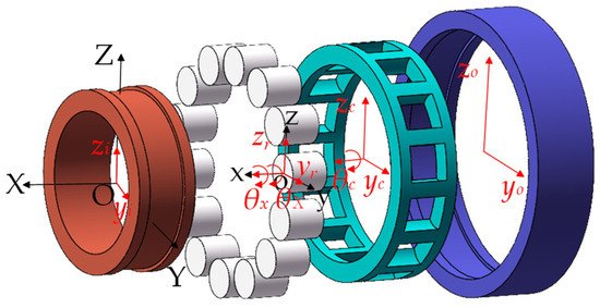
Figure 1.
Schematic diagram of bearing coordinate system and degrees of freedom.
The established model is based on the following assumptions: Internal components are considered as rigid bodies, deformations are neglected, and the center of mass coincides with the geometric center. The cage pocket shape is assumed to be rectangular. In the model, only the translational degrees of freedom in the longitudinal direction are considered for the inner and outer rings , , , . The cage is considered to have translational degrees of freedom in two directions and rotational freedom around the bearing axis , , . The rolling elements are considered to have translational degrees of freedom in the longitudinal and vertical directions, as well as rotational motion, including revolution around the bearing axis and rotation around their axes , , , . The established cylindrical roller bearing model, comprising N rolling elements, possesses a total of 4N + 7 degrees of freedom.
2.2. Bearing Dynamic Differential Equations
By analyzing the forces acting on the rolling elements, cage, and inner and outer rings, dynamic differential equations are established for each component.
- (1)
- Differential Equation of Rolling Element Motion
At a certain moment during the motion process, the internal force analysis of the j-th rolling element under the combined effect of horizontal Y and vertical Z loads in the angle of the bearing is shown in Figure 2. The rolling element primarily bears the forces from the inner and outer rings, the cage, and the resistance from the lubricating oil. In the figure, and represent the contact forces between the inner and outer races and the rolling element, and represent the drag forces from the inner and outer races on the rolling element, is the centrifugal force acting on the rolling element, is the contact force between the rolling element and the cage, is the tangential friction force from the cage on the rolling element, is the resistance from the lubricating oil to the rolling element’s revolution, is the inner ring rotational speed, is the cage rotational speed, and is the rolling element’s rotational speed.
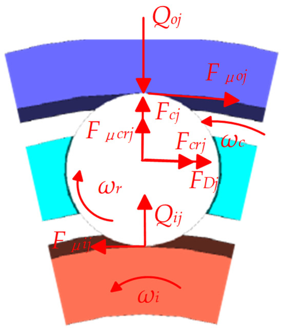
Figure 2.
Schematic diagram of forces acting on the rolling element.
The contact forces , between the rolling element and the inner and outer races of the bearing are [18]
where and represent the contact stiffness of the roller and the inner and outer races, which can be calculated according to reference [19]. For the roller bearing, n is 10/9; and represent the relative displacement between the rolling elements and the inner and outer raceway. The subscripts i and o represent the inner and outer rings, r respent the rolling elements, respectively, and j represents the j-th rolling element (and similarly for other references) [20].
where , , , and represent the radii of the inner and outer races, the radius of the rolling element, and the revolution radius of the rolling element; , , , , , and represent the displacements of the inner and outer rings, as well as the rolling element, in the y and z directions; is the angular position of the rolling element.
The drag forces from the inner and outer races on the rolling element are as follows:
where and represent the drag coefficients between the rolling element and the inner and outer races [21], determined by the Hertzian contact stress P and the slip velocity V at the contact point [22].
The centrifugal force exerted on the rolling element is
where is the mass of the rolling element; is the pitch diameter of the bearing.
The contact force between the rolling element and the cage is
where is the contact stiffness between the rolling element and the cage [21]; is the contact deformation between the rolling element and the cage [18].
The tangential friction force between the rolling element and the cage pocket is modeled using Coulomb friction, expressed as
where is the coefficient of friction between the rolling element and the cage.
The resistance from the lubricating oil to the rolling element’s revolution is [18]
where is the drag coefficient; is the density of the lubricating oil; is the revolution speed of the rolling element , ; is the diameter of the rolling element.
The Reynolds number of the lubricating oil can be defined as
where is the viscosity of the lubricating oil; the corresponding drag coefficient can be determined based on the Reynolds number using the data provided in Table 2-1 of reference [23].
The frictional torque exerted by the cage on the rolling element is
The torque exerted by the lubricating oil on the rolling element’s rotation is
where is the cylindrical surface area of the rolling element; is the shear stress of the lubricating oil.
Based on the above analysis, the differential equations for the rolling element’s rotation, revolution, and motion along the y and z axes are established as follows:
where and are the diameters of the inner and outer races; and are the moments of inertia for the rolling element’s rotation and revolution.
- (2)
- The differential equation of the cage’s motion
The forces acting on the cage are shown in Figure 3. The cage is primarily subjected to the normal contact force and the tangential friction force from the rolling elements; the force is the interaction force between the inner ring guiding surface and the cage guiding surface, the unbalanced force , and the torque from the lubricating oil.
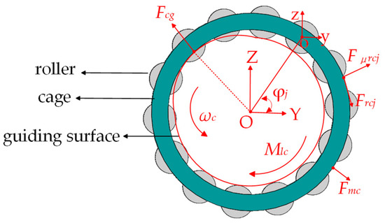
Figure 3.
Schematic diagram of the forces acting on the cage.
The resisting torque exerted by the lubricating oil on the cylindrical surface of the cage [24] is
where is the surface area of the cage guiding surface; is the diameter of the cage guiding surface.
The unbalanced force of the cage is represented as
where is the unbalanced mass of the cage; and are the components of in the horizontal and vertical directions; the calculation of the force between the cage guiding surface and the inner ring guiding surface is referenced from [25].
Based on the above analysis, the differential equation for the cage’s motion is established as follows:
where is the moment of inertia of the cage around the X-axis; and are the horizontal and vertical components of .
- (3)
- The differential equation of the outer ring’s motion
The outer ring is primarily subjected to the forces from the rolling elements and the lubricating oil. The differential equation of the outer ring’s motion is established as follows:
where is the mass of the outer ring.
- (4)
- The differential equation of the inner ring’s motion
The forces acting on the inner ring are shown in Figure 4. In the figure, the inner ring is primarily subjected to the radial load , . and are obtained from the bogie wheel-rail coupling dynamic model in Section 2.3.
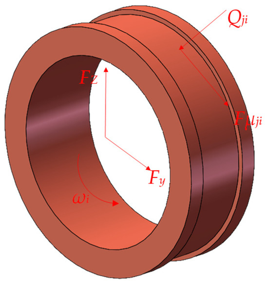
Figure 4.
Schematic diagram of the forces acting on the inner ring.
The differential equation of the inner ring’s motion is established as follows:
where is the mass of the inner ring.
2.3. Bogie Wheel-Rail Coupling Dynamic Modeling and Wheel-Rail Excitation Load
Based on multibody dynamics theory through Simpack, a multibody bogie wheel-rail coupling dynamic model is established. The model includes one car body, two frames, four wheelsets, four gearboxes, four large gears, four small gears, and eight axle boxes. The car body, frame, and wheelsets are connected to the ground using a 7# joint, which has six degrees of freedom. The axle box, gearbox, wheelset, and large and small gears are connected using a 2# joint, which has only the freedom of rotation in the vehicle’s transverse direction. A single-stage helical gear transmission is used between the gearbox and the large and small gears. The large gear and the wheelset are constrained by joint 0#, which has no degrees of freedom, while the small gear shafts are rigidly connected to the motor. The gear meshing characteristics inside the gearbox are applied as force element 225# between the large and small gears. The 225# force element is used to handle the gear contact, allowing for the gear pair displacement coefficient, friction coefficient, and tooth profile modification. Based on the input gear parameters, it calculates the gear meshing stiffness according to the DIN 3990-1-1987 standard [26]. The vehicle model topology is illustrated in Figure 5.
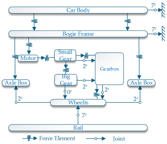
Figure 5.
Vehicle model topology diagram.
When building a solid model in Simpack, a substitute modeling method is used. Many structural components of high-speed trains appear in pairs, sharing the same material properties and similar geometric structures. For a high-speed train, one car comprises two bogies, and each bogie includes two wheelsets, two frames, two crossbeams, four axle boxes, and two gearboxes. It’s only necessary to establish a substructure model for one of each component, after which the remaining components can be duplicated directly via copy-and-paste. Then, import the corresponding structural parameters to complete the detailed modeling process.
- (1)
- The concentrated mass model is used in the car body, taking into account only its mass and inertia.
- (2)
- Components of the bogie system are associated using corresponding force elements.
- (3)
- The transmission system is modeled using high and controlled active transmission installed via 25# geometric elements, and the characteristics of the grid between large and small gears are simulated using the force supply element 225#.
- (4)
- Based on the topology of the vehicle model and the association between the body and the bogie of the car, a complete model of the rigid body of the train is obtained by calling the bogie substructure model and clarifying it in the car body model.
- (5)
- The track model adopts the CN60 rail type, with the wheel tread profile set as LMA. Track irregularity excitation is based on the measured “Wuhan–Guangzhou” track excitation spectrum (hereinafter referred to as the “Wu-Guang spectrum”).
Wheel polygonization refers to the radial deviation caused by non-uniform wear along the circumferential direction of the wheel. Polygonal wheels exhibit significant waveforms of different orders, which are typically described using a harmonic function [27] to represent different orders of wheel polygonization, as follows:
where is the wheel circumferential irregularity diameter difference; is the wheel polygon wear amplitude, i.e., the wave depth; is the order of the wheel polygon; is the initial phase angle; is the actual wheel radius; is the nominal radius of the wheel’s rolling circle. Different wheel polygon excitations are simulated by varying the amplitude and order .
The loads and at the center of mass of the inner ring of the gearbox small gear input shaft cylindrical roller bearing are obtained and used as the boundary loads for the bogie gearbox bearing. The dynamic characteristics of the bearing and the variation in internal contact loads under rail-traction disturbance are then calculated. The schematic diagram of the load excitation transmission is shown in Figure 6.
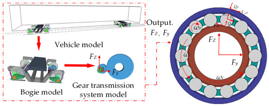
Figure 6.
Schematic diagram of load excitation transmission.
3. Example Parameters and Model Validation
Taking the CRH380B bogie gearbox input cylindrical roller bearing NU214 as an example, the validity of the model is verified. The main structural parameters of the bearing are shown in Table 1, while the main structural parameters of the bogie and gear pair are shown in Table 2 and Table 3.

Table 1.
Bearing parameters.

Table 2.
Main parameters of the bogie.

Table 3.
Gear pair meshing parameters.
To validate the effectiveness of the established model, the simulation results of the cage angular velocity and the rolling element spin angular velocity were compared with their theoretical values at a vehicle operating speed of 200 km/h without considering wheel-rail disturbances. The theoretical calculations for the cage angular velocity and the rolling element spin angular velocity are as follows [28]:
where is the contact angle.
To validate the effectiveness of the established model, the simulation results of the cage angular velocity and the rolling element’s spin angular velocity were also compared with their theoretical values at a vehicle operating speed of 200 km/h without considering wheel-rail disturbances. The comparison results are illustrated in Figure 7.
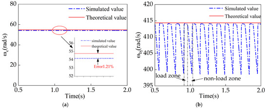
Figure 7.
Comparison of simulated and theoretical values of cage and rolling element angular velocities. (a) Cage angular velocity. (b) Rolling element spin angular velocity.
In the simulation analysis, time-varying characteristics were considered, leading to fluctuations in both the cage angular velocity and the rolling element’s spin angular velocity. Notably, the rolling element’s angular velocity remained relatively stable within the load zone while exhibiting lower and more unstable values outside this zone. Therefore, we compared the average cage angular velocity and the average rolling element spin angular velocity within the load zone to their respective theoretical calculations.
The comparison revealed a discrepancy of 1.21% between the simulated and theoretical cage angular velocities. For the rolling element’s spin angular velocity, the theoretical value was 414.1765 rad/s, while the simulated average within the load zone was 414.3685 rad/s, resulting in a minimal error of just 0.05%.
These findings indicate a strong agreement between the simulated and theoretical values for both the cage angular velocity and the rolling element’s spin angular velocity, with errors remaining below 2%. This consistency verifies the validity of the model presented in this study.
4. Dynamic Analysis of Gearbox Bearings Under Wheel-Rail Excitation
To analyze the impact of wheel-rail excitations on the dynamic characteristics of gearbox bearings at a vehicle operating speed of 200 km/h, four working conditions, as shown in Table 4, were selected. These conditions encompass various polygonal orders and amplitudes, as well as the combined effects of wheel polygonal excitations and track irregularities. Then, the influence of these factors on the internal contact loads and vibration characteristics of the bearings was further investigated.

Table 4.
Working conditions.
4.1. Variation Patterns of Internal Contact Forces in Bearings Under Wheel-Rail Excitations
To analyze the impact of wheel polygonal excitation on the internal load characteristics of bearings, the wheel-rail excitation was introduced in the proposed gearbox bearing dynamic model. In the absence of track irregularities, we selected a wheel polygonal amplitude of 0.1 mm and systematically analyzed the variations in internal contact loads between the rolling elements and the outer ring of the gearbox bearing under different wheel polygonal orders. Figure 8 illustrates the time-domain and frequency-domain characteristics of the contact load between the rolling element and the outer ring under four conditions.
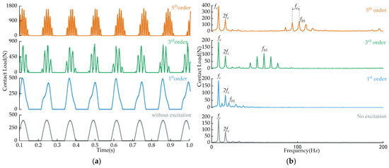
Figure 8.
Contact load between rolling element and outer ring at different orders. (a) Time-domain plot. (b) Frequency-domain plot.
To analyze the frequency components of internal contact loads in bearings, the wheel polygonal excitation frequency [27] and the cage rotational frequency [28] were introduced.
where is the rotational frequency of the bearing’s inner ring; is the order of the wheel polygon; is the wheel diameter; is the vehicle speed; is the pitch diameter of the bearing; is the diameter of the rolling element.
From the time-domain plots of contact loads between the rolling element and the outer ring in Figure 8a, it is evident that these contact loads exhibit periodic variations, with alternating load-bearing and non-load-bearing zones. Compared to the without-excitation scenario, introducing wheel polygonal excitation and increasing the polygonal order from one to five leads to a rise in the maximum contact load between the rolling elements and the outer ring within the load-bearing zone—from 405.2645 N to 1655.4 N, marking a 308% increase. This indicates that wheel polygonal excitation significantly amplifies the contact load between the rolling element and the outer ring. In the absence of wheel polygonal excitation, the rolling element and the outer ring experience a single impact within the load-bearing zone. However, under wheel polygonal excitation, multiple impacts occur between the rolling element and the outer ring within this zone. Higher polygonal orders result in more frequent impacts, leading to frequent contact between the rolling elements and the bearing’s outer ring. This phenomenon arises due to the periodic uneven wear along the wheel tread circumference caused by wheel polygonal excitation, which induces periodic excitation forces [27]. As depicted in Figure 8b, higher wheel polygonal orders correspond to increased excitation frequencies. During vehicle operation, wheel polygonal excitation transmits through the wheelset to the gearbox and ultimately to the bearing’s inner ring, causing severe vibrations of the inner ring, which increases the contact load between the rolling elements and the outer ring, leading to multiple impacts. Prolonged exposure to such adverse load conditions can result in bearing failures and reduced service life.
Further analysis of the frequency components of the contact loads between the rolling elements and the outer ring, as shown in the frequency-domain plots in Figure 8b, reveals that, in the absence of excitation, only the cage rotational frequency ( = 8.5 Hz) and its harmonics appear in the frequency domain. Upon introducing wheel polygonal excitation, the frequency domain exhibits the excitation frequencies of the wheel polygons— = 20.57 Hz (Fundamental frequency of the first-order wheel polygon), = 61.73 Hz (fundamental frequency of the third-order wheel polygon), = 102.85 Hz (fundamental frequency of the fifth-order wheel polygon)—along with coupled frequencies involving the cage rotational frequency. This further corroborates the previously mentioned reason for the occurrence of multiple impacts in the contact loads between the rolling elements and the outer ring.
To investigate the influence of wheel polygonal amplitude on the internal contact load between the rolling elements and the outer ring of the bogie gearbox bearing, particular attention is given to the third-order polygon, which is frequently observed among low-order polygons. Four scenarios are considered: no wheel-rail excitation, and wheel polygonal amplitudes of 0.05 mm, 0.1 mm, and 0.15 mm.
By examining these conditions, the relationship between varying polygonal amplitudes and the resulting contact loads within the bearing was elucidated, as shown in Figure 9. Unlike increasing the order of wheel polygonization, which elevates both the contact load and the frequency of impacts between rolling elements and the outer ring, augmenting the amplitude of wheel polygonization at a constant order solely intensifies the contact load without altering the number of impacts. In the absence of excitation, the maximum contact load between the rolling elements and the outer ring is 405.2645 N. Introducing a third-order wheel polygonal excitation with an amplitude of 0.15 mm elevates this maximum contact load to 1061.7 N, marking a 162% increase. Although increasing the amplitude of wheel polygonization does not change the excitation frequency experienced by the bearing, it amplifies the vibration amplitude of the bearing’s inner ring, thereby escalating the contact load between the rolling elements and the outer ring. In the frequency domain, it is evident that the amplitude of the wheel polygonal excitation frequency component within the contact load between the rolling elements and the outer ring increases with the polygonization amplitude.
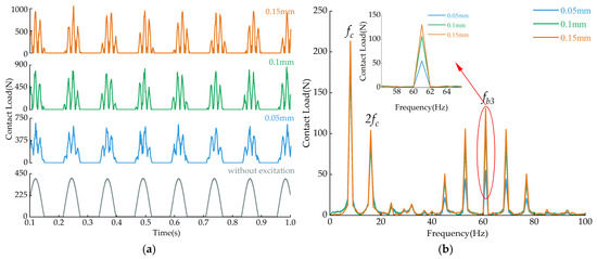
Figure 9.
Contact load between rolling elements and outer ring at different amplitudes. (a) Time-domain plot. (b) Frequency-domain plot.
Wheel-rail excitations typically encompass inputs from both the wheel and the track. To analyze the effects of individual and combined wheel polygonal excitations and track irregularities on bearing load characteristics, we compare the contact loads between the rolling elements and the outer ring of the bearing under three scenarios: a third-order wheel polygonal condition with an amplitude of 0.1 mm, a track irregularity condition, and a combined condition involving both excitations.
From the time-domain comparison results of the contact load between the rolling elements and the outer ring in Figure 10a, it is evident that under track irregularity excitation, the contact load within the load-bearing zone exhibits irregularities due to the randomness of track irregularities. In the absence of excitation, the maximum contact load between the rolling elements and the outer ring is 405.2645 N. When track irregularities are introduced, this maximum increases by 50% to 607.9937 N. Under the sole influence of a third-order wheel polygonal excitation with a 0.1 mm amplitude, the maximum contact load rises by 112% to 860.8323 N compared to the without-excitation scenario, indicating that such a wheel polygonal excitation has a more significant impact on bearing contact load than track irregularities. When both wheel polygonal excitation and track irregularities act simultaneously, the maximum contact load reaches 1050.2 N, representing a 159% increase over the no-excitation case and increases of 72% and 22% over the individual effects of wheel polygonal excitation and track irregularities, respectively. This demonstrates that the combined excitation from both the wheel and track further amplifies the contact load between the rolling elements and the outer ring.
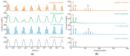
Figure 10.
Contact load between rolling elements and outer ring under combined wheel-rail and wheel polygonal excitations. (a) Time-domain plot. (b) Frequency-domain plot.
4.2. Dynamic Characteristics of Bearings Under Wheel-Rail Excitation
To analyze the frequency components of the bearing’s inner and outer rings, as well as the cage, under conditions with and without wheel-rail excitation, the bearing’s natural frequency and the gear meshing frequency are introduced.
where represents the number of teeth on the driving gear and denotes the rotational speed of the driving gear.
As shown in Figure 11, under conditions without wheel-rail excitation, the vibration responses of the bearing’s inner and outer rings, as well as the cage, exhibit the bearing’s natural frequency Hz. In the low-frequency range, the vibrations of the inner and outer rings are primarily dominated by this natural frequency. In the high-frequency range, the gear meshing frequency Hz significantly influences the vibrations, especially affecting the inner ring. For the cage, the frequency domain is mainly characterized by its rotational frequency Hz and its coupling frequencies with the bearing’s natural frequency, while the gear meshing frequency has a minimal impact on the cage’s vibrations.
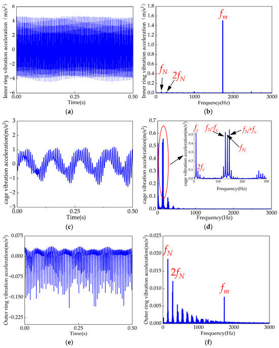
Figure 11.
Time-domain and frequency-domain plots of vibration acceleration for each bearing component without wheel-rail excitation. (a) Time-domain inner ring vibration acceleration. (b) Frequency-domain inner ring vibration acceleration. (c) Time-domain cage vibration acceleration. (d) Frequency-domain cage vibration acceleration. (e) Time-domain outer ring vibration acceleration. (f) Frequency-domain outer ring vibration acceleration.
As shown in Figure 12, under wheel-rail excitation, the bearing’s inner and outer rings, as well as the cage, are subjected to low-frequency excitations caused by track irregularities and wheel polygonal excitation. The excitations affecting the inner and outer rings are primarily attributed to wheel polygonal excitations and gear meshing excitations. Similar to the no-excitation case, the inner ring is most significantly influenced by the gear-meshing frequency. In the frequency domain, the cage is predominantly affected by the wheel polygonal excitation frequency and its coupling frequencies with the cage’s rotational frequency.
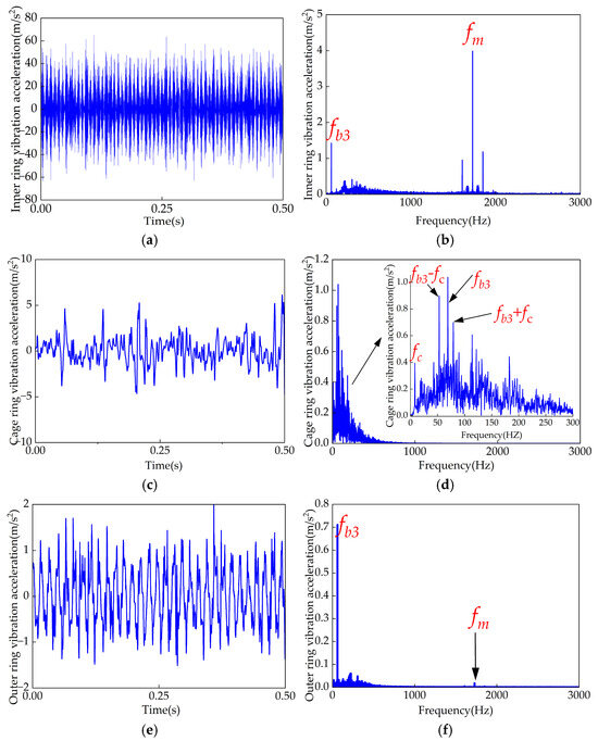
Figure 12.
Time-domain and frequency-domain plots of vibration acceleration for each bearing component under wheel-rail excitation. (a) Time-domain inner ring vibration acceleration. (b) Frequency-domain inner ring vibration acceleration. (c) Time-domain cage vibration acceleration. (d) Frequency-domain cage vibration acceleration. (e) Time-domain outer ring vibration acceleration. (f) Frequency-domain outer ring vibration acceleration.
To analyze the vibration characteristics of the inner and outer rings, as well as the cage of a bearing under wheel polygonal excitation, the third operating conditions, varying the wheel polygonal order from one to five and the amplitude from 0.05 mm to 0.15 mm, were selected. And the root mean square (RMS) values of vibration acceleration for the gearbox bearing of the bogie under the same order with different amplitudes and under the same amplitude with different orders were compared. The comparison results are presented in Figure 13.
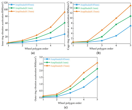
Figure 13.
Influence of wheel polygon order and amplitude on the root mean square (RMS) values of vibration acceleration for various bearing components. (a) Inner ring vibration acceleration RMS. (b) Cage ring vibration acceleration RMS. (c) Outer ring vibration acceleration RMS.
From Figure 13, it is evident that the root mean square (RMS) value of the vibration acceleration of the bearing’s inner ring is greater than that of the outer ring and the cage. Additionally, the RMS values of vibration acceleration for the inner ring, cage, and outer ring all increase with the rise in the order and amplitude of the wheel polygonal excitation. This indicates that wheel polygonal excitation intensifies the bearing’s vibration, with the inner ring experiencing the most pronounced vibration. This is because the bearing inner ring is directly connected to the gearbox input shaft through an interference fit. The wheel polygonal excitation increases the interaction force between the wheel and rail, which is transmitted through the wheelset to the gearbox. The inner ring directly bears this excitation force, which is then transmitted to the rolling elements, driving the cage and ultimately reaching the outer ring. When the wheel polygonal order is relatively low, an increase in polygonal amplitude has a minor effect on bearing vibration. However, when the polygonal order exceeds the second order, the root mean square (RMS) values of vibration for all bearing components increase significantly. As the polygonal amplitude increases from 0.05 mm to 0.15 mm, at the second order of wheel polygonization, the RMS vibration acceleration of the bearing inner ring, cage, and outer ring increases by 178%, 68%, and 24%, respectively. When the polygonal order reaches the fifth order, the RMS vibration acceleration of the bearing inner ring, cage, and outer ring increases by 229%, 113%, and 67%, respectively. These results indicate that the vibration of the bearing is directly influenced by both the order and amplitude of the wheel polygonization.
To assess the vibration characteristics of internal bearing components under wheel-rail excitation, we compared the root mean square (RMS) values of vibration acceleration for each bearing part under two conditions: wheel-rail excitation and wheel polygonal excitation (referred to as conditions 3 and 4, respectively). As illustrated in Figure 14, the RMS values of vibration acceleration for all bearing components increase with the rise in wheel polygonal order under both excitation scenarios. Notably, when the wheel polygonal order increases from the first to the fifth, the RMS value of the inner ring’s vibration acceleration under wheel-rail excitation is 1.76 times (first order), 1.23 times (second order), and 1.02 times (third order) that under wheel polygonal excitation alone. This trend indicates that as the wheel polygonal order increases, the impact of wheel-rail excitation on bearing vibration diminishes compared to wheel polygonal excitation alone. The cage and outer ring exhibit similar trends.
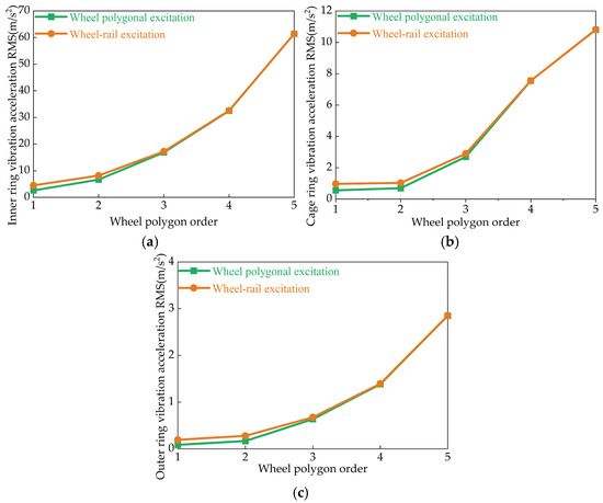
Figure 14.
Comparison of the effect of wheel-rail and wheel polygon excitations on RMS values of vibration acceleration of each bearing component. (a) Inner ring vibration acceleration RMS. (b) Cage ring vibration acceleration RMS. (c) Outer ring vibration acceleration RMS.
The underlying reason is that track irregularities introduce low-frequency excitations below 50 Hz. At lower wheel polygonal orders, the excitation frequencies of the wheel polygons are close to those of track irregularities, leading to resonance and, consequently, more intense bearing vibrations. As the wheel polygonal order increases, its excitation frequency moves away from that of track irregularities. Although the RMS values of vibration acceleration under wheel-rail excitation continue to rise, the rate of increase diminishes.
5. Conclusions
In this study, a dynamic model for the cylindrical roller bearing at the input end of a bogie gearbox was established by analyzing the forces acting on the rolling elements, inner and outer rings, and cage. The validity of the model was verified through the velocity characteristics of the internal components. Furthermore, a simulation method for obtaining external wheel-rail excitations for the gearbox bearing was also proposed. This approach was used to analyze the transmission and characteristics of internal loads within the gearbox bearing under wheel-rail excitations. Comparative analyses were conducted on the internal contact loads and vibration characteristics of various components under different wheel polygonal excitations and track irregularities. The following conclusions were drawn:
- (1)
- Wheel polygonal excitation causes multiple impacts between the rolling element and the outer ring. As the polygonal order increases from the first to the fifth order, the number of impacts between the rolling elements and the outer ring also increases, leading to more frequent contact. An increase in polygonal order also results in a higher contact load between the rolling elements and the outer ring. Compared to the case without excitation, the contact load under the fifth-order wheel polygonal excitation increases by 308%. On the other hand, an increase in polygonal amplitude only leads to an increase in the contact load between the rolling element and the outer ring. Compared to the case without excitation, when the amplitude of the third-order wheel polygonal excitation increases from 0.05 mm to 0.15 mm, the contact load increases by 162%.
- (2)
- When the coupling effect of wheel polygonal excitation and track irregularity excitation occurs, the contact load between the rolling element and the outer ring is greater than when each excitation acts independently. Compared to the case of third-order wheel polygonal excitation alone and track irregularity excitation alone, the contact load under coupled excitation increases by 22% and 72%, respectively.
- (3)
- Wheel polygonal excitation increases the vibration of the bearing’s inner ring, outer ring, and cage. As the polygonal order increases from the first to the fifth order and the amplitude increases from 0.05 mm to 0.15 mm, the RMS values of vibration for the bearing inner ring, outer ring, and cage also increase accordingly.
- (4)
- Track irregularity excitation further increases the vibration of the bearing. However, due to the low-frequency nature of track irregularity excitation, its impact on the RMS vibration of the bearing is more significant under the first two orders of wheel polygonal excitation.
Author Contributions
Investigation and writing by M.W.; simulation, data curation, and writing by Q.Y., data processing by X.L., simulation model of bearing by Z.Z., simulation model and idea by B.W., writing—review by J.Z. All authors have read and agreed to the published version of the manuscript.
Funding
The National Natural Science Foundation of China [Youth Science Fund Project No. 51905069]; the General Project of the Liaoning Provincial Department of Education [No.LJKMZ20220864]; Dalian City Major science and technology Foundation [2024JB11PT004] and [2023YF12GX016]; Liaoning Province Science and Technology Development Project [2024JH6-10020004]; Natural Science Foundation of Liaoning Province [2023-MS-280].
Data Availability Statement
The original contributions presented in the study are included in the article; further inquiries can be directed to the corresponding author.
Conflicts of Interest
The authors declare no conflicts of interest.
References
- Garg, V.K.; Dukkipati, R.V. Dynamics of Railway Vehicle Systems; Academic Press: Toronto, ON, Canada, 1984. [Google Scholar] [CrossRef]
- Wickens, A.H. Fundamentals of Rail Vehicle Dynamics: Guidance and Stability; Swets & Zeitlinger: Lisse, The Netherlands, 2003. [Google Scholar] [CrossRef]
- Lyon, D. The calculation of track forces due to dipped rail joints, wheel flats and rail welds. In Proceedings of the Second ORE Colloquium on Technical Computer Programs, Derby, UK, 16–18 May 1972. [Google Scholar]
- Jenkins, H.H.; Stephenson, J.E.; Clayton, G.A.; Morland, G.W.; Lyon, D. The effect of track and vehicle parameters on wheel/rail vertical dynamic forces. Railw. Eng. J. 1974, 3, 2–16. [Google Scholar]
- Zhai, W.M.; Sun, X. A Detailed Model for Investigating Vertical Interaction between Railway Vehicle and Track. Veh. Syst. Dyn. 1994, 23 (Suppl. S1), 603–615. [Google Scholar] [CrossRef]
- Zhai, W.M.; Wang, K.Y.; Cai, C.B. Fundamentals of vehicle–track coupled dynamics. Veh. Syst. Dyn. 2009, 47, 1349–1376. [Google Scholar] [CrossRef]
- Wang, K.; Liu, P.; Zhai, W.; Huang, C.; Chen, Z.; Gao, J. Wheel/rail dynamic interaction due to excitation of rail corrugation in high-speed railway. Sci. China Technol. Sci. 2014, 58, 226–235. [Google Scholar] [CrossRef]
- Chen, D.L.; Liu, J.X.; Du, K.J.; Wang, Y. Analysis of the deterioration of harmonic local irregularity on locomotive wheel-rail vertical force. Appl. Mech. Mater. 2014, 684, 137–144. [Google Scholar] [CrossRef]
- Yao, Y.; Zhang, H.J.; Liu, Y.M.; Li, S.H. The dynamic study of locomotives under saturated adhesion. Veh. Syst. Dyn. 2011, 49, 1321–1338. [Google Scholar] [CrossRef]
- Huang, G.; Zhou, N.; Zhang, W. Effect of internal dynamic excitation of the traction system on the dynamic behavior of a high-speed train. Proc. Inst. Mech. Eng. Part F J. Rail Rapid Transit 2016, 230, 1899–1907. [Google Scholar] [CrossRef]
- Huang, G.; Zhang, W.; Zhou, N.; Wu, P. Vibration characteristics of gear transmission system of high-speed train under dynamic excitation. J. China Railw. Soc. 2014, 36, 1–8. [Google Scholar]
- Huang, G. Dynamic response analysis of gearbox housing system subjected to internal and external excitation in high-speed train. Chin. J. Mech. Eng. 2015, 51, 95–101. [Google Scholar] [CrossRef][Green Version]
- Jiang, H.; Dai, Y.; Liu, F.; Wang, P.; Wu, P. Dynamic responses of the high-speed train with polygonal wheels considering gear transmissions. Proc. Inst. Mech. Eng. Part C J. Mech. Eng. Sci. 2024, 239, 686–702. [Google Scholar] [CrossRef]
- Wu, H.; Wu, P.; Li, F.; Liu, Q.; Zhai, W. Fatigue analysis of the gearbox housing in high-speed trains under wheel polygonization using a multibody dynamics algorithm. Eng. Fail. Anal. 2019, 100, 351–364. [Google Scholar] [CrossRef]
- Yin, Z.; Zhang, J. Dynamic responses of gear transmission system of high-speed train due to wheel polygonal wear. In Proceedings of the 2020 International Conference on Mechanical Engineering and Applied Mechanics, Shanghai, China, 15–17 December 2020; pp. 827–833. [Google Scholar] [CrossRef]
- Wang, Z.; Yin, Z.; Allen, P.; Wu, P.; Zhai, W. Dynamic analysis of enhanced gear transmissions in the vehicle-track coupled dynamic system of a high-speed train. Veh. Syst. Dyn. 2021, 60, 2716–2738. [Google Scholar] [CrossRef]
- Zeng, J. Effect of rotor vibration of traction motor on dynamic behavior of high-speed train. Eng. Mech. 2011, 28, 238–244. (In Chinese) [Google Scholar]
- Yang, Y.; Wang, J.; Wang, M.; Liu, Y.; Li, X. Dynamic modeling and behavior of cylindrical roller bearings considering roller skew and the influence of eccentric load. Lubricants 2024, 12, 317. [Google Scholar] [CrossRef]
- Sarangi, M.; Majumdar, B.; Sekhar, A.S. Stiffness and damping characteristics of lubricated ball bearings considering the surface roughness effect. Part 1: Theoretical formulation. Proc. Inst. Mech. Eng. Part J J. Eng. Tribol. 2004, 218, 529–538. [Google Scholar] [CrossRef]
- Yang, Y.; Qi, X.; Wang, Y.; Liu, Y.; Li, X. Dynamic characteristics of a cylindrical roller bearing with cage cracks. Lubricants 2025, 13, 25. [Google Scholar] [CrossRef]
- Wang, Y.; Zhang, G.; Wang, E. Traction behavior of No. 4129 synthetic oil for space lubrication. J. Fail. Anal. Prev. 2019, 19, 138–143. [Google Scholar] [CrossRef]
- Cui, Y.; Deng, S.; Yang, H.; Zhang, W.; Niu, R. Effect of cage dynamic unbalance on the cage’s dynamic characteristics in high-speed cylindrical roller bearings. Ind. Lubr. Tribol. 2019, 71, 1125–1135. [Google Scholar] [CrossRef]
- Harris, T.A. An analytical method to predict skidding in high-speed roller bearings. ASLE Trans. 1966, 9, 229–241. [Google Scholar] [CrossRef]
- Gupta, P.K. Advanced Dynamics of Rolling Elements; Springer: New York, NY, USA, 1984; ISBN 978-0-387-96031-9. [Google Scholar]
- Wen, B. Theoretical and Experimental Investigation of Cage Dynamics in Angular Contact Ball Bearing. Ph.D. Thesis, Dalian University of Technology, Dalian, China, 2017. (In Chinese). [Google Scholar]
- Chen, Z.; Tang, L.; Yang, J.; Chen, Z.; Zhai, W. Dynamic Characteristics Analysis of Mountainous Rack Railway Vehicle-Track Coupled System Considering Gear-Rack Dynamic Excitation. J. Mech. Eng. 2023, 59, 163–173. (In Chinese) [Google Scholar]
- Wang, Z.; Allen, P.; Mei, G.; Wang, R.; Zhang, W.; Yin, Z. Influence of wheel-polygonal wear on the dynamic forces within the axle-box bearing of a high-speed train. Veh. Syst. Dyn. 2020, 58, 1385–1406. [Google Scholar] [CrossRef]
- Wang, H.; Han, Q.; Zhou, D. Nonlinear dynamic modeling of rotor system supported by angular contact ball bearings. Mech. Syst. Signal Process. 2017, 85, 16–40. [Google Scholar] [CrossRef]
Disclaimer/Publisher’s Note: The statements, opinions and data contained in all publications are solely those of the individual author(s) and contributor(s) and not of MDPI and/or the editor(s). MDPI and/or the editor(s) disclaim responsibility for any injury to people or property resulting from any ideas, methods, instructions or products referred to in the content. |
© 2025 by the authors. Licensee MDPI, Basel, Switzerland. This article is an open access article distributed under the terms and conditions of the Creative Commons Attribution (CC BY) license (https://creativecommons.org/licenses/by/4.0/).