Article

Effect of Nozzle Geometry on Erosion Characteristics in Abrasive Water Jet: Experimental and Numerical Analysis

Precision Polishing and Measuring Laboratory, Guangxi University, Nanning 530000, China
*
Authors to whom correspondence should be addressed.
Lubricants 2025, 13(3), 132; https://doi.org/10.3390/lubricants13030132
Submission received: 16 December 2024 / Revised: 1 March 2025 / Accepted: 17 March 2025 / Published: 19 March 2025

Abstract

:
In the field of abrasive-water-jet polishing technology, the influence of nozzle geometry on nozzle wear and internal-structure erosion in abrasive-water-jet polishing technology is studied, and the nozzle design is optimized through experiments and a numerical simulation to improve the stability and efficiency of the abrasive jet. The mathematical model between the cross-sectional area of the nozzle and the dimensionless length of the nozzle is established, as well as the variation in the static pressure of the nozzle and the length of the nozzle. Through Fluent simulation, it is found that when the nozzle length is 12 mm, the abrasive-phase acceleration is sufficient and the erosion intensity is minimal. After 480 h of erosion experiments, the erosion profile of nozzle cavity was detected. The results show that the erosion strength of the 12 mm nozzle is the least, followed by the 6 mm nozzle, and the 18 mm nozzle is the strongest, which is consistent with the simulation results.

1. Introduction

The jet nozzle is a very important part of ultra-precision polishing and its structural design directly affects the polishing accuracy of the processed parts. The parameters that usually affect the jet nozzle include nozzle cavity size, nozzle length-to-diameter ratio, abrasive flow rate, and so on.
The size of the inner diameter and length of the nozzle also has a great impact on the performance of the jet nozzle. The size and length of the inner diameter of the nozzle determines the size of the nozzle internal pressure and export flow; the larger the inner diameter, the greater the internal water pressure. While the nozzle outlet length and outlet diameter directly affect the fluid velocity—the smaller the nozzle outlet diameter, the faster the flow rate—the corresponding outlet flow rate will be reduced [1]. An increase in outlet length leads to an increase in inertial resistance and frictional resistance, slowing down the flow rate, but can increase the stability of the nozzle [2]. To obtain the velocity change curves of abrasive particles along the axis under different water-nozzle diameters, Narayanan et al. [3] carried out simulation experiments on the nozzles with outlet diameters of 0.5, 0.75, and 1 mm, respectively. In the optimization design of jet nozzles, parameters such as jet angle and jet area need to be considered comprehensively, and an erosion model was established to achieve a model close to the actual polishing purpose [4]. It is possible to adjust the shape of the nozzle outlet and the spray angle to achieve the balance of the jet velocity and the jet diffusion angle to gain the optimal spraying effect [5]. At the same time, attention should also be paid to the manufacturing process of the nozzle and the selection of materials to guarantee the reliability or life cycle of the nozzle in practical applications [6].
However, fewer studies have been conducted on particle erosion in the internal flow path of abrasive water nozzles. Studies on erosion inside nozzles have been carried out in two main ways: experiments and numerical simulations. Most of the existing studies indicate that polishing particle structure, flow rate, and pressure have important effects on nozzle wear. The increase in flow velocity would lead to an increase in particle impact force. The increase in pressure would aggravate the erosion of the flow-channel wall. Therefore, optimizing nozzle structure and operating parameters are essential to reduce wear and extend nozzle service life [7,8,9]. Park et al. [10] studied the erosion process of nozzle particles under liquid–solid flow conditions and gained insights into the principle of nozzle erosion by particles.
Li et al. [11] simulated the particle flow inside the nozzle by the computational fluid dynamics method and verified it by erosion experiments. Shao et al. [12] analyzed the process of erosion and the sensitivity of the impact characteristics to different parameters by extracting the trajectories of incident particles in different regions. The impact characteristics of the particles and the erosion mechanism of particles on nozzles were analyzed by the surface morphology and impact characteristics of the inner wall [13].
The change in the nozzle jet is affected by factors such as shape, internal structure, and pressure drive, resulting in differences in jet characteristics [14]. The experiments conducted by Chen et al. [15] show that different shaped nozzles behave differently under different pressures. Chen et al. [16] found that the exponential gemstone nozzle has the best performance, followed by the straight-cone type, and the flat-top gemstone nozzle has the worst overall performance through a numerical simulation of five different gemstone nozzles. Kim et al. [17] studied the orthotropic and quadrilateral nozzles to analyze the influence of different orifice shapes on the jet characteristics of nozzles at different pressures through a combination of theory and experiment. Finally, it was found that these two anisotropic nozzles are less prone to automatization and have high clustering characteristics compared to the circular nozzles. Tesar et al. [18] conducted a study on polygonal nozzles by establishing a mathematical model of their emission characteristics and their simulation model was established by using the simulation toolbox. It was found that the velocity of the jet increases with the rate of change in the cross-sectional area of the nozzle outlet. The nozzle length increases and the pressure of the water column inside the nozzle increases significantly along the nozzle exit direction finally. The flow characteristics of nano-nozzles depend approximately on the geometry of their cross-section. Velocity distributions and density numbers are given and discussed for five different cross-sections of nano nozzles at three different measurement scales [19]. Gadge et al. [20] stated that the internal structure of the nozzle directly affects the life of the nozzle and the effectiveness of mixing abrasiveness with water.
The effect of nozzle geometry on nozzle wear and internal-structure erosion in abrasive-water-jet polishing technology is studied in this paper. The nozzle design is optimized by experiment and numerical simulation. The nozzle static-pressure mathematical model was established by optimizing the nozzle cavity structure with Fluent 14.0 and Matlab 2018a. Finally, the advantages of 12 mm nozzle cylinder length are verified by wear experiments.

2. Simulation and Result Analysis of Nozzles

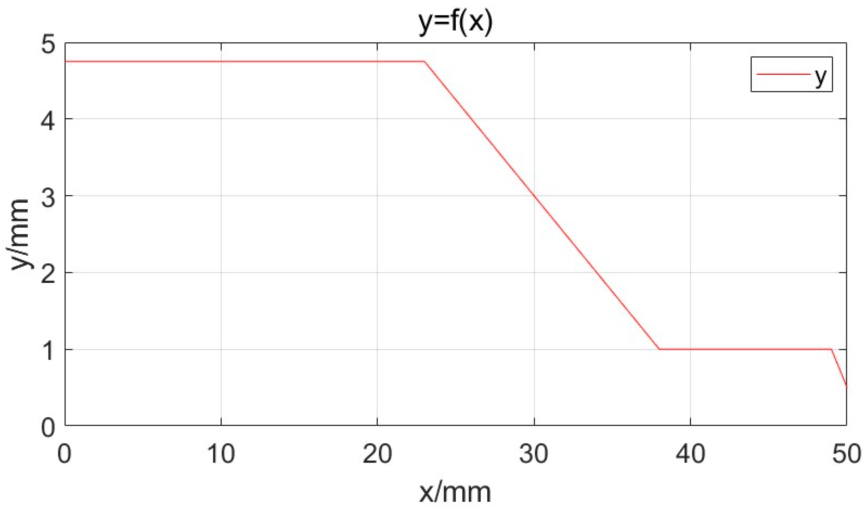
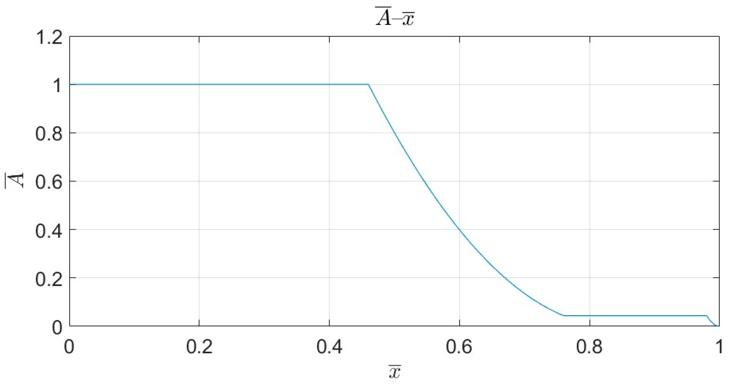
2.1. Mathematical Modeling of Nozzles

Garrison [21,22,23] studied the static pressure of shaped nozzles and found that changes in nozzle shape have a significant effect on the centerline velocity gradient. However, they are insensitive to changes in nozzle size and face velocity. An empirical representation of velocity and static-pressure loss data was finalized for nozzle design calculations.
Based on the physical model of the nozzle, a right-angle coordinate system can be established which yields the following equations for the inner contour of a straight conical nozzle:
y = 4.75 , 0 x 23 0.25 x + 10.5 , 23 x 38 1 , 38 x 49 x + 50 , 49 x 50
The inner contour curve of the nozzle is shown in Figure 1:
The internal cross-sectional area of the nozzle is related to the length x as
A x = A ( x ) = π × 4.75 2 = 70.882 , 0 x 23 π 16 x 2 5.25 π × x + 110.25 π , 23 x 38 π , 38 x 49 π 4 x 2 25.5 π × x + 650.25 π , 49 x 50 : Or   A x = A 0
where A(x) is the cross-sectional area in X section, mm2; X is the value of axial coordinate of the nozzle section, mm, and A0 is the cross-sectional area of the nozzle inlet, where A ¯ = A / A 0 , x ¯ = x / L , A0 = π × 4.752 = 70.882 mm2, and the total length of the nozzle is L = 50 mm, referring to the dimensionless cross-sectional area and dimensionless length, respectively. Therefore, the relationship between dimensionless cross-sectional area and dimensionless length is shown in Figure 2, and the change rule of cross-sectional area of the nozzle along the axial direction is shown in Figure 3.

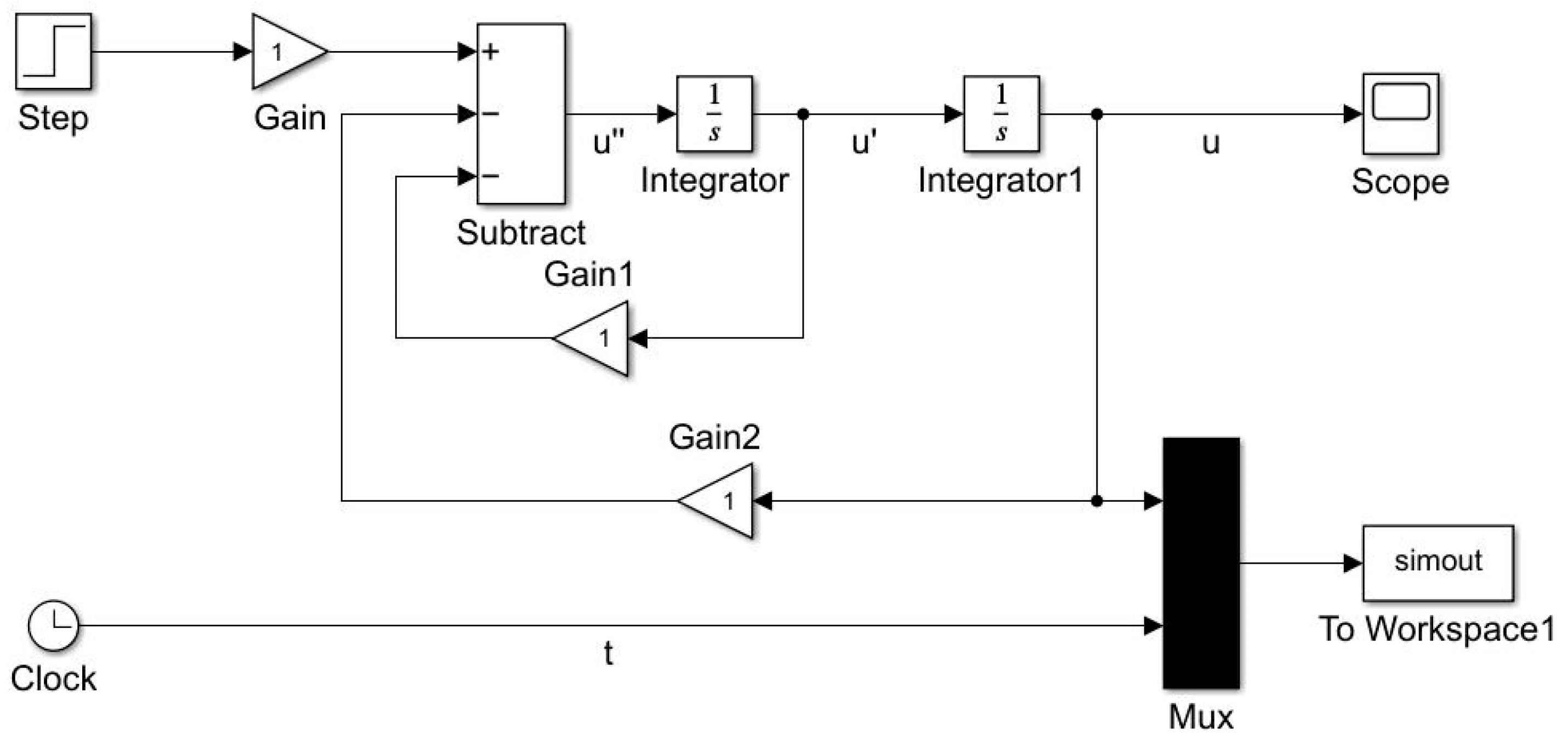
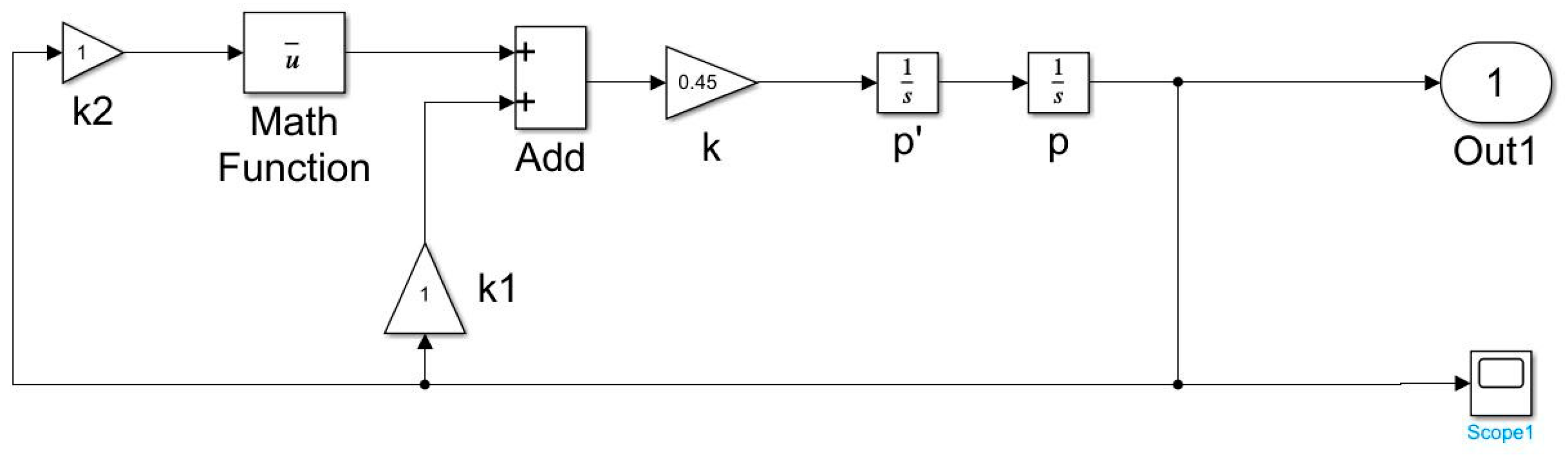
2.2. Matlab Simulation of Nozzle

In order to establish the mathematical model of the nozzle in MATLAB, appropriate differential equations, water-jet exit velocity, and the static pressure in the nozzle of the mathematical model are established according to the existing structure of the nozzle size as well as the fluid dynamics and hydraulic transmission of the relevant knowledge.
After establishing the mathematical model of the nozzle, a simulation model was built in MATLAB, which is shown in Figure 4 and Figure 5. They are the simulation models of the exit velocity of the pulse jet and the static pressure inside the nozzle. The step time of the step module is set to 0 and the other options are selected by default in Figure 4. The initial conditions of the integrator (Integrator) are set to 0. In Figure 5, the initial conditions of the integrator (Integrator) are set to 0.163 and 1.
Considering the boundary conditions, u ¯ ( x ¯ , 0 ) = 1 ; ρ ¯ ( x ¯ , 0 ) = 1 ; p ¯ ( x ¯ , 0 ) = 0 , it can be observed that the relation between the pressure change in the nozzle pressure along the nozzle length is as follows:
d p d x ¯ = 1 4 ln A e ¯ A e ¯ ( l ¯ ) 3 2
the relation between the dimensionless velocity and the dimensionless outlet area is as follows
d 2 u ¯ d A e ¯ 2 = d u ¯ d A e ¯ 2 A e ¯ ln A e ¯ 1 A e ¯ ln A e ¯ A e ¯
The pressure in the nozzle increases significantly along the axial direction of the nozzle in Figure 6. The shorter the length of the nozzle, the faster the pressure in the nozzle rises.

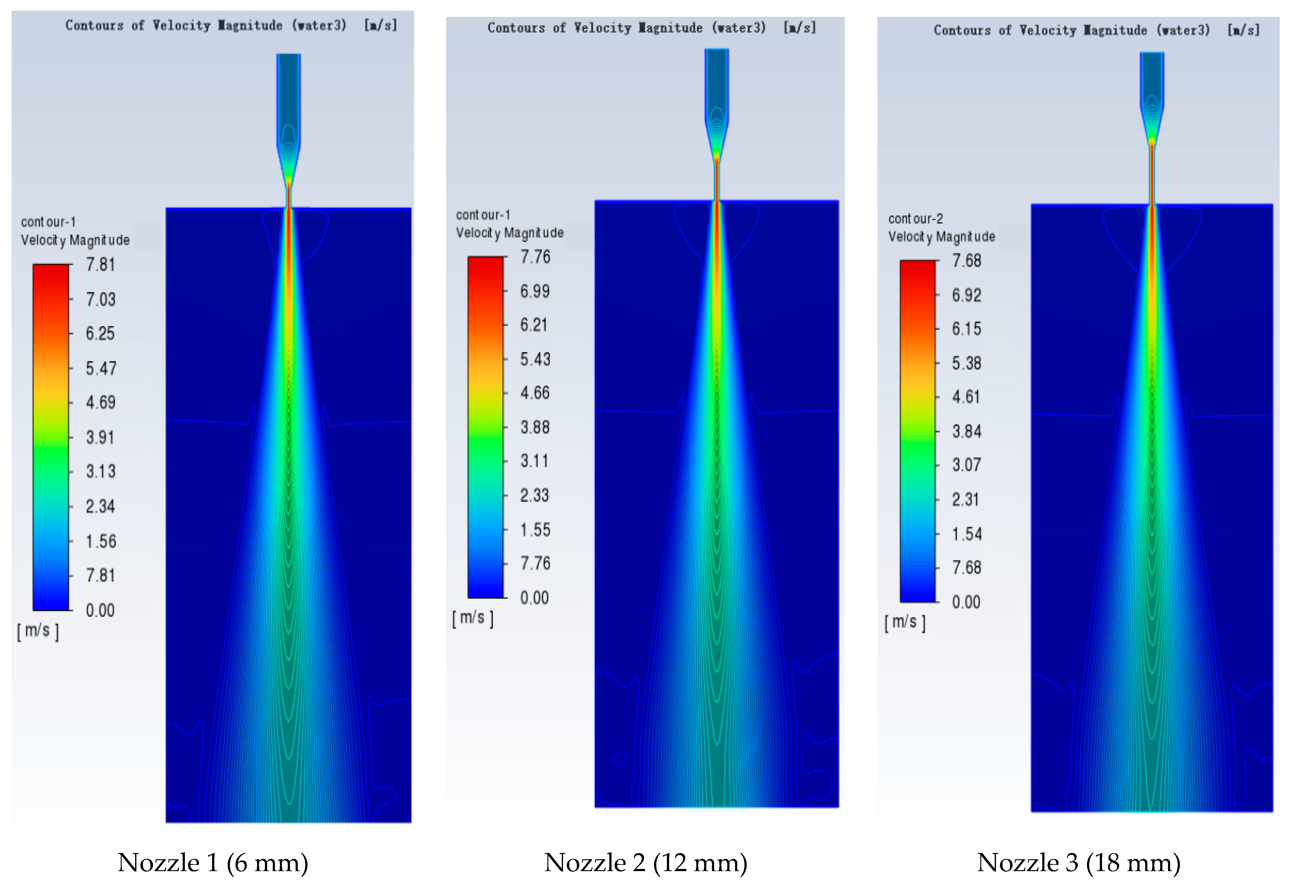
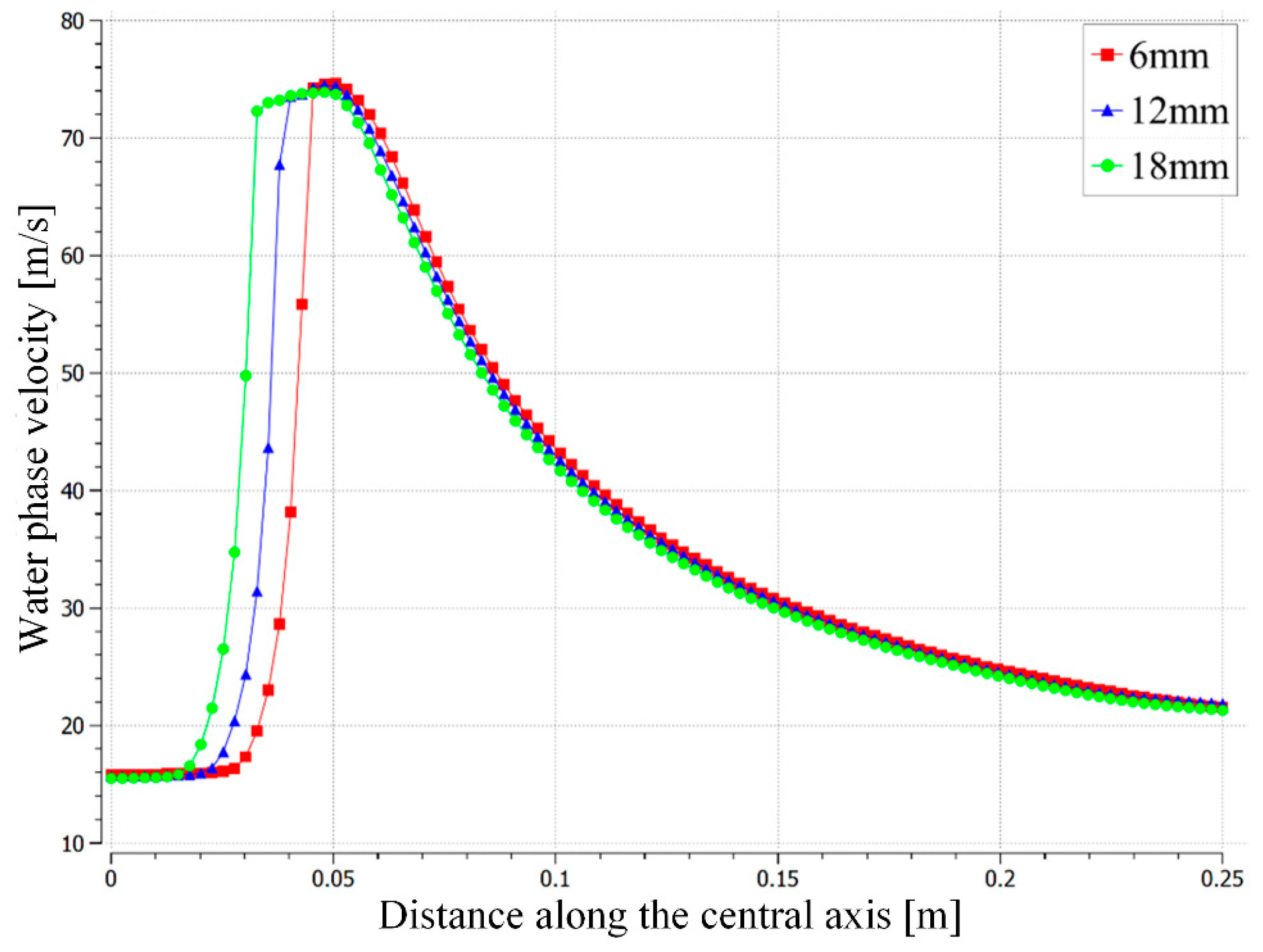
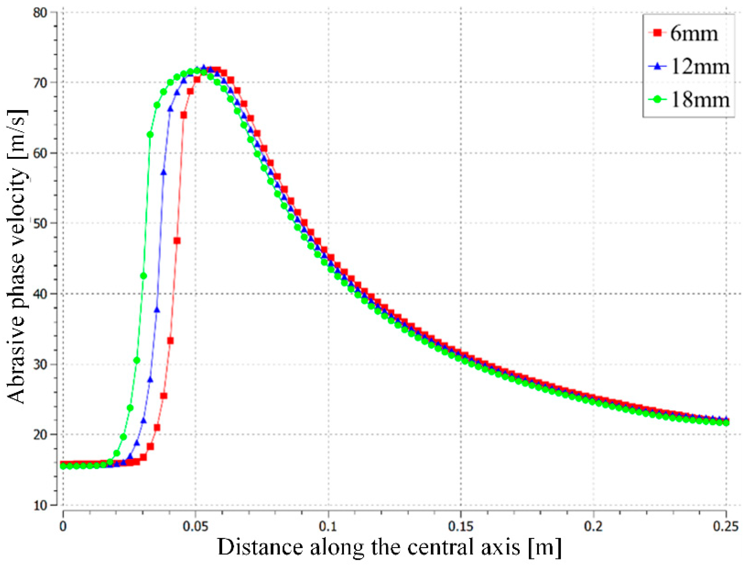
2.3. Fluent Analysis of Different Structure Nozzles

The cylinder section of the nozzle is connected to the contraction section to make the jet accelerate from the contraction section, which exerts a certain stabilizing effect on the jet after it has been intensely accelerated. It improves its convergence and stability and makes the overall jet speed higher. The length of the cylinder section affects the jet performance. The inlet pressure is set at 3 MPa. The three different cases of cylinder length selected for Fluent analysis are 6 mm, 12 mm, and 18 mm. Other nozzle parameters are consistent which are shown in Table 1 below.
According to the abrasive-water-jet numerical simulation method in the above section, the modeling and simulation analyses of the three conical linear nozzles were carried out based on Fluent. Figure 7 is the velocity-distribution cloud diagram of the water phase in the abrasive water jet generated by the three conical nozzles, and Figure 8 is the velocity-distribution cloud diagram of the abrasive phase.
The peak velocity of the three nozzles is similar because of the same contraction angle, and the acceleration effect of the nozzle on the jet is basically the same for the water phase and abrasive phase in Figure 7 and Figure 8.
The simulation results of three kinds of cylindrical length nozzles were imported into CFD-Post for post-processing and the velocity curves of the jets produced by the three nozzles at the central axis were compared. Figure 9 is a comparison of the jet velocity of the water phase and Figure 10 is a comparison of the jet velocity of the abrasive phase.
The peak velocity of the water phase of the three nozzles is very close on the central axis in Figure 9. The nozzle with a cylindricity length of 18 mm decelerates first due to having the longest cylindrical section, followed by 12 mm and 6 mm at the nozzle exit. However, the difference is not large and the speed of the three nozzles on the central axis is similar.
It is shown in Figure 10 that the longer the cylinder section, the faster the abrasive phase speed at the nozzle exit, because the longer acceleration distance makes the abrasive phase accelerate more fully. This project is to simulate the lower-pressure environment whose pressure is only 4 MPa, and only a slight speed difference can be seen. The jet performance of nozzles with different cylinder lengths under submerged conditions at 50 MPa was studied and the above conclusions were obviously reached.
It is shown in Figure 11 and Figure 12 that for the water phase and abrasive phase, the peak velocity of nozzles with different cylinder lengths are not in the same position. In order to better compare the velocity distribution on the jet cross-section, the peak velocity positions on the central axis of three nozzles are selected, respectively. The cross-section is set and the two-phase velocity on the cross-section is compared. Figure 11 shows the velocity comparison of the water phase and Figure 12 shows the velocity comparison of the abrasive phase.
The velocity distribution on the cross-section exists in two different regions in Figure 12. In the region near the central axis, the abrasive-phase velocity increases slightly with the increase in the length of the cylinder section, but the velocity of the water phase and the abrasive phase decreases significantly with the increase in the length of the cylinder section in the jet part away from the central axis. This is due to the friction between the jet and the inner wall of the nozzle. A longer cylinder segment leads to a greater friction loss of kinetic energy and decreases the overall jet velocity.

3. Experiments

3.1. Experimental Equipment

Although a 304 stainless-steel nozzle is not as hard as a tungsten-steel nozzle, its plastic deformation ability is stronger than tungsten steel. The erosion experiment was carried out in the ultra-precision Polishing Laboratory of Guangxi University. The experimental system consists of five independent systems: an injection system, an abrasive mixing system, a detection system, a flow regulation system, and a three-axis operating platform system. The flowing abrasive liquid produced by the metering pump is transported through a high-pressure pipe to the nozzle outlet. The liquid power in the test is provided by the metering pump, as shown in Figure 13a. Figure 13b provides the injection system and Figure 13c shows the nozzles of three different structures in the experiment. The test parameters are shown in Table 2.

3.2. Experimental Methods

The abrasive liquid is composed of aluminum oxide, pure water, and ZW-S06 type phosphate compound additive. The concentration of the abrasive is 100 g/L, the concentration of the additive is 1 wt%, and the average particle size of the abrasive is about 1000 nm. After the abrasive and liquid are pre-mixed, they are transported to the nozzle through the metering pump for the erosion test. In this experiment, the power of the metering pump was set at 3 MPa while the experimental time of the nozzle lasted for 480 h. After the experiment, the nozzle cavity was micro-detected. The specific detection platform is shown in Figure 14.

4. Results and Discussions

4.1. Nozzle Erosion Distribution

The small size of the nozzle hole makes it difficult for the cavity erosion to be accurately captured by traditional measuring instruments. The distribution of nozzle erosion shows significant spatial variation in different locations. In particular, the erosion effect is negligible in the upper part of the cavity contraction zone of nozzle. In contrast, the flow field inside the nozzle is simulated to further optimize the nozzle design and reduce erosion. By comparing and analyzing the flow-field characteristics of different nozzle structures, the research results show that the velocity distribution at the nozzle entrance has a significant influence on the flow pattern inside the nozzle. It is found that under the condition of high-speed flow, the increase in particle kinetic energy leads to more severe impact on the wall at the junction of the nozzle contraction zone and the linear section, which intensifies the erosion problem in this area. Therefore, the design and optimization between the shrunken section and the straight-line section is very important to improve the durability and performance of the nozzle.

4.2. Analysis of Abrasive Flow Trajectory

The distribution characteristics of liquid affect the impact strength of abrasive particles with the surrounding medium or wall, which is very important for predicting and controlling the movement and impact behavior of particles [24,25,26,27]. From Figure 15, Figure 16 and Figure 17, the flow field shows obvious directional changes along the Y-axis at different positions of the nozzle. The wear pattern of the etch belt studied by Shao et al. reveals the following phenomena: Figure 16 shows that the microstructure of nozzle 3 and the main erosion area has suffered serious erosion damage, which is consistent with the previous numerical simulation results. The particle erosion mechanism of the nozzle’s cavity is shown in Figure 15. Driven by the hydrodynamic effect, the velocity direction of abrasive particles shows slight differences at different positions. When the abrasive particles accelerate further in the liquid and hit the nozzle wall with an inclination angle, the impact effect of the particles on the nozzle wall and the material will be triggered. In addition, the material that falls off the wall is removed with the continuous movement of the abrasive medium and finally intensify the repeated cutting and erosion of the particles on the inner wall of the nozzle, which is shown in Figure 17.

5. Conclusions

In this paper, the influence of nozzle geometry on nozzle wear and internal-structure erosion in abrasive-water-jet polishing technology is discussed, and the nozzle design is optimized by experiments and numerical simulation to improve the stability and efficiency of abrasive jet.
The increase in the length of the cylinder section makes the acceleration of the abrasive phase more adequate, so that the abrasive phase is too long to obtain a greater speed. However, the longer cylindricity will lead to a longer friction distance between the cavity of nozzle and abrasive-water-jet flow at the same time, resulting in more energy loss. The jet velocity near the wall will decrease significantly, resulting in a decrease in the average velocity of the entire jet. It is considered that the nozzle length-diameter ratio of l/d should be between 3 and 7, and the length of the cylinder section should be between 6 and 14 mm for this topic. It clearly reveals the microscopic morphology of the main erosion area of the nozzle by SEM. These features include scratches and depressions on the surface of the material and micro-cracks caused by the impact of abrasive particles. The gradual accumulation of these microscopic damages intensifies the wear degree of the inner wall of the nozzle, and thus shortens the service life of the nozzle. Therefore, optimizing the nozzle structure to reduce erosion damage is the core of improving the nozzle durability.

Author Contributions

X.C.: Conceptualization, Software, Data Curation, Writing, Visualization; L.C.: Methodology, H.P.: Supervision. All authors have read and agreed to the published version of the manuscript.

Funding

The authors would like to acknowledge the academic and technical support of Guangxi University. This project was financially supported by the Guangxi Science and Technology Major Project (No. AA18118002) and the Guangxi Bagui Scholars Special Fund (No. 2019A02).

Data Availability Statement

The original contributions presented in this study are included in the article. Further inquiries can be directed to the corresponding authors.

Conflicts of Interest

The authors declare no conflict of interest.

References

  1. Yu, J.; Li, J.; Wang, Q.; Zhang, X.; Zhang, S. Numerical and experimental study on the duration of nozzle starting of the reflected high-enthalpy shock tunnel. Appl. Sci. 2022, 12, 2845. [Google Scholar] [CrossRef]
  2. Ma, H.; Ren, W.; Yao, F.; Cheng, B.; Sun, Z.; Deng, H.; Gao, K. Prediction of gas-solid nozzle performance based on CFD and response surface methodology. Powder Technol. 2024, 442, 119871. [Google Scholar] [CrossRef]
  3. Smith, J.; Lee, K. Modelling of abrasive particle energy in water jet machining. J. Mater. Process. Technol. 2013, 213, 2201–2210. [Google Scholar]
  4. Tamannaee, N.; Spelt, J.K.; Papini, M. Abrasive slurry jet micro-machining of edges, planar areas and transitional slopes in a talc-filled co-polymer. Precis. Eng. 2016, 43, 52–62. [Google Scholar] [CrossRef]
  5. Lehnert, T.; Nguyen, D.; Baldi, L.; Gijs, M. Glass reflow on 3-dimensional micro-apertures for electrophysiological measurements on-chip. Microfluid. Nanofluidics 2007, 3, 109–117. [Google Scholar] [CrossRef]
  6. Karstensen, A.; Seipp, T.; Nadarajah, C. Life management of pressure swing absorbers, in proceedings of asme. Press. Vessel. Pip. Conf. 2023, 2, pvp2023. [Google Scholar]
  7. Akkurt, A. Cut front geometry characterization in cutting applications of brass with abrasive water jet. J. Mater. Eng. Perform. 2009, 19, 599–606. [Google Scholar] [CrossRef]
  8. Du, M.; Wang, H.; Dong, H.; Guo, Y.; Ke, Y. Numerical research on multi-particle movements and nozzle wear involved in abrasive waterjet machining. Int. J. Adv. Manuf. Technol. 2021, 117, 2845–2858. [Google Scholar] [CrossRef]
  9. Li, Z.; Yao, S.; Yun, F.; Wang, X.; Wang, L.; Wu, Y. Simulation and Optimization of the Nozzle Section Geometry for a Suspension Abrasive Water Jet. Machines 2022, 10, 3. [Google Scholar] [CrossRef]
  10. Park, S.; Kainuma, S.; Yang, M.Y.; Kim, A.; Ikeda, T.; Toyota, Y.; Arakawa, T. Advancements in abrasive water-jet treatment for efficient surface cleaning and comprehensive corrosion removal in steel structures. J. Build. Eng. 2024, 84, 108623. [Google Scholar] [CrossRef]
  11. Li, K.K.; Peng, J.M.; Li, Y.L.; Ge, D.; Li, J.M. Performance prediction of solid particle erosion in fluidic oscillators for fluidic hammers based on CFD-DPM. Powder Technol. 2023, 428, 118819. [Google Scholar] [CrossRef]
  12. Shao, C.F.; Ge, Z.L.; Zhou, Z.; Liu, W.C.; Li, Z.T.; Tian, C.; Chang, W.X. Experimental and numerical investigation of abrasive water jet nozzle erosion. Powder Technol. 2023, 430, 119031. [Google Scholar] [CrossRef]
  13. Perec, A. Experimental research into alternative abrasive material for the abrasive water-jet cutting of titanium. Int. J. Adv. Manuf. Technol. 2018, 97, 1529–1540. [Google Scholar] [CrossRef]
  14. Gong, C.; Ou, M.X.; Jia, W.D. The effect of nozzle configuration on the evolution of jet surface structure. Results Phys. 2019, 15, 102572. [Google Scholar] [CrossRef]
  15. Chen, L.H.; Gao, D.R.; Cheng, M.Z.; Cai, Y.; Guo, L.W. Effect of Special-Shaped Nozzle Structure on Water Jet Performance. Processes 2022, 10, 2066. [Google Scholar] [CrossRef]
  16. Chen, X.C.; Deng, S.S.; Guan, J.F.; Hua, W.X. Experiment and simulation research on abrasive water jet nozzle wear behavior and anti-wear structural improvement. J. Braz. Soc. Mech. Sci. Eng. 2017, 39, 2023–2033. [Google Scholar] [CrossRef]
  17. Kim, J.; Park, H.S.; Lee, J.; Moon, H.K.; Bang, M.; Cho, H.H. Effect of Misalignment at the Flat and Profiled Endwall of Nozzle Guide Vane on Heat Transfer. Int. J. Heat Mass Transf. 2024, 230, 125750. [Google Scholar] [CrossRef]
  18. Tesar, V. Characterisation of inexpensive, simply shaped nozzles. Chem. Eng. Res. Des. 2010, 88, 1433–1444. [Google Scholar] [CrossRef]
  19. Nowruzi, H.; Ghassemi, H. Effects of Nano-nozzles cross-sectional geometry on fluid flow: Molecular dynamic simulation. J. Mech. 2018, 34, 667–678. [Google Scholar] [CrossRef]
  20. Gadge, M.; Lohar, G.; Chinchanikar, S. A review on micro-blasting as surface treatment technique for improved cutting tool performance. Mater. Today Proc. 2022, 64, 725–730. [Google Scholar] [CrossRef]
  21. Garrison, R.P.; Byers, D.H. Statis pressure, velocity, and noise characteristics of rectangular nozzles for high velocity/low volume exhaust ventilation. Am. Ind. Hyg. Assoc. J. 1980, 41, 855–863. [Google Scholar] [CrossRef] [PubMed]
  22. Garrison, R.P.; Byers, D.H. Static pressure and velocity characteristics of circular nozzles for high velocity/low volume exhaust ventilation. Am. Ind. Hyg. Assoc. J. 1980, 41, 803–811. [Google Scholar] [CrossRef] [PubMed]
  23. Garrison, R.P.; Erig, M. Airflow Characteristics of Two Symmetric Exhaust Inlets and of a Single Inlet near an External Boundary Surface. Appl. Ind. Hyg. 1988, 3, 182–188. [Google Scholar]
  24. Huang, F.; Mi, J.Y.; Li, D.; Wang, R.R. Impinging performance of high-pressure water jets emitting from different nozzle orifice shapes. Geofluids 2020, 2020, 8831544. [Google Scholar] [CrossRef]
  25. Xiao, S.Q.; Ge, Z.L.; Ren, Q.Y.; Liu, J.L.; Wang, H.Y. Numerical analysis on the flow field structure and deflection characteristics of water jets under nozzle moving conditions. Eng. Appl. Comput. Fluid Mech. 2020, 14, 1279–1301. [Google Scholar] [CrossRef]
  26. Urazmetov, O.; Cadet, M.; Teutsch, R.; Antonyuk, S. Investigation of the flow phenomena in high-pressure water jet nozzles. Chem. Eng. Res. Des. 2021, 165, 320–332. [Google Scholar] [CrossRef]
  27. Jiang, T.W.; Huang, Z.W.; Li, J.B.; Zhou, Y.S.; Xiong, C. Experimental investigation of internal and external flow fields of jetting nozzles with different structures. J. Pet. Sci. Eng. 2022, 217, 110891. [Google Scholar] [CrossRef]
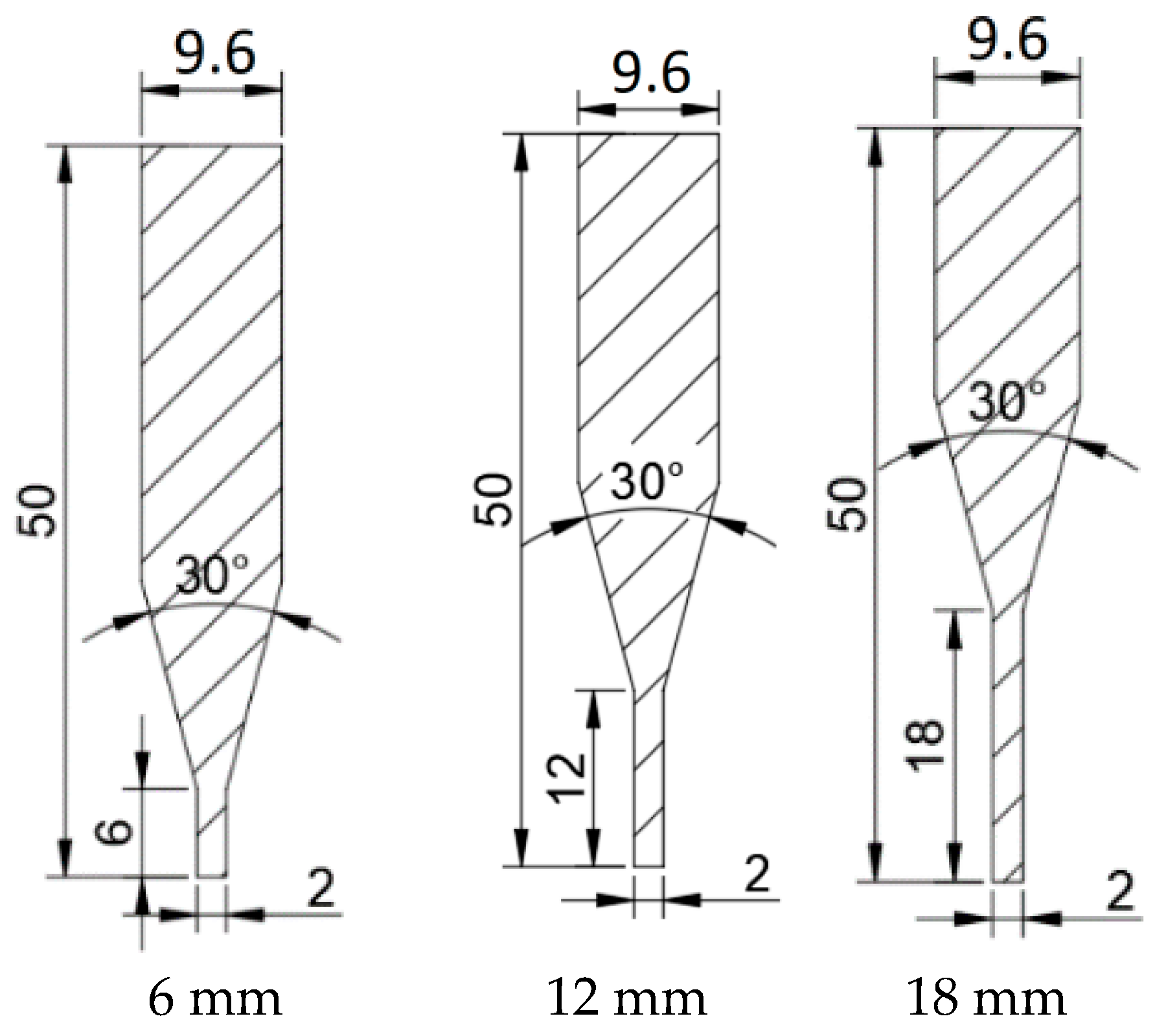
Figure 1. Inner contour curve of nozzle.
Lubricants 13 00132 g001
Figure 2. Relationship curve between dimensionless cross-sectional area and dimensionless length.
Lubricants 13 00132 g002
Figure 3. Three different lengths of cylindrical sections of the nozzles.
Lubricants 13 00132 g003
Figure 4. Simulation model of nozzle exit velocity.
Lubricants 13 00132 g004
Figure 5. Simulation model of static pressure inside nozzle.
Lubricants 13 00132 g005
Figure 6. Static pressure in different nozzles.
Lubricants 13 00132 g006
Figure 7. Cloud image of water-phase velocity distribution of nozzles with three different cylinder lengths.
Lubricants 13 00132 g007
Figure 8. Cloud image of abrasive-phase velocity distribution of nozzles with three different cylinder lengths.
Lubricants 13 00132 g008
Figure 9. Comparison of water phase velocities along the central axis.
Lubricants 13 00132 g009
Figure 10. A comparison of abrasive phase velocities along the central axis.
Lubricants 13 00132 g010
Figure 11. Comparison of water-phase velocity in cross-section.
Lubricants 13 00132 g011
Figure 12. Comparison of abrasive-phase velocity on cross-section.
Lubricants 13 00132 g012
Figure 13. Abrasive-water-jet test platform: (a) metering pump; (b) jet system; (c) test nozzles with three kinds of structures.
Lubricants 13 00132 g013
Figure 14. Microstructure detection platform of nozzles: (a) Hitachi electron microscope S-3400; (b) cross-section of nozzles 1 and 2; (c) cross-section of nozzle 2 and 3.
Lubricants 13 00132 g014
Figure 15. Morphological characteristics of nozzle 2’s erosion surface.
Lubricants 13 00132 g015
Figure 16. Morphological characteristics of nozzle 3’s erosion surface.
Lubricants 13 00132 g016
Figure 17. Morphological characteristics of nozzle 1’s erosion surface.
Lubricants 13 00132 g017
Table 1. Nozzle structure parameters.
Overall Length of Nozzle Inlet DiameterContraction AngleOutlet Diameter
50 mm9.6 mm30°2 mm
Table 2. Technological conditions of experiments.
ParameterExperiment ValueData Range
Hydraulic pressure3 MPa2~4 MPa
Abrasive particle flow rate 1 g/s0.725 g/s~1.25 g/s
Abrasive particle diameter1 μm0.5 μm, 1 μm
Disclaimer/Publisher’s Note: The statements, opinions and data contained in all publications are solely those of the individual author(s) and contributor(s) and not of MDPI and/or the editor(s). MDPI and/or the editor(s) disclaim responsibility for any injury to people or property resulting from any ideas, methods, instructions or products referred to in the content.

