Article

Influence of Engine Oils on Pre-Ignition Tendency in a Hydrogen–Kerosene Dual-Fuel Engine

1
Institute of Powertrain and Automotive Technology, TU Wien, 1060 Vienna, Austria
2
Castrol Technology Center, BP p.l.c., Whitchurch Hill, Pangbourne, Berkshire RG8 7QR, UK
*
Author to whom correspondence should be addressed.
Lubricants 2025, 13(3), 126; https://doi.org/10.3390/lubricants13030126
Submission received: 11 February 2025 / Revised: 13 March 2025 / Accepted: 15 March 2025 / Published: 16 March 2025

Abstract

:
Reducing CO2 emissions is an increasingly important goal in general aviation. The dual-fuel hydrogen–kerosene combustion process has proven to be a suitable technology for use in small aircraft. This robust and reliable technology significantly reduces CO2 emissions due to the carbon-free combustion of hydrogen during operation, while pure kerosene or sustainable aviation fuel (SAF) can be used in safety-critical situations or in the event of fuel supply issues. Previous studies have demonstrated the potential of this technology in terms of emissions, performance, and efficiency, while also highlighting challenges related to abnormal combustion phenomena, such as knocking and pre-ignition, which limit the maximum achievable hydrogen energy share. However, the causes of such phenomena—especially regarding the role of lubricating oils—have not yet been sufficiently investigated in hydrogen engines, making this a crucial area for further development. In this paper, investigations at the TU Wien, Institute of Powertrain and Automotive Technology, concerning the role of different engine oils in influencing pre-ignition tendencies in a hydrogen–kerosene dual-fuel engine are described. A specialized test procedure was developed to account for the unique combustion characteristics of the dual-fuel process, along with a detailed purge procedure to minimize oil carryover. Multiple engine oils with varying compositions were tested to evaluate their influence on pre-ignition tendencies, with a particular focus on additives containing calcium, magnesium, and molybdenum, known for their roles in detergent and anti-wear properties. Additionally, the study addressed the contribution of particles to pre-ignition occurrences. The results indicate that calcium and magnesium exhibit no notable impact on pre-ignition behavior; however, the addition of molybdenum results in a pronounced reduction in pre-ignition events, which could enable a higher hydrogen energy share and thus decrease CO2 emissions in the context of hydrogen dual-fuel aviation applications.

1. Introduction

To advance the defossilization of the aviation sector, sustainability considerations have grown increasingly prominent. Aviation currently contributes about 1 gigaton of CO2 emissions per year, accounting for roughly 10% of the transportation sector’s total greenhouse gases [1].
To address these emissions, new propulsion strategies are essential. Alongside sustainable aviation fuels (SAFs), hydrogen (H2) stands out as a promising zero-carbon alternative, provided it is generated from renewable sources. Hydrogen’s key benefits include its carbon-free exhaust, high energy density per unit mass, and favorable combustion properties [2].
Internal combustion engines (ICEs) are commonly employed in small aircraft due to their reliability, cost-effectiveness, and comparatively high efficiency under elevated loads. Compared to fuel cells, hydrogen-fueled ICEs are also more tolerant of a lower fuel purity. Hydrogen can be introduced via external mixture formation—most notably port fuel injection (PFI), which is straightforward and cost-effective but reduces volumetric efficiency and entails a backfire risk—or through direct injection (DI), which mitigates backfire and maintains volumetric efficiency, yet necessitates higher pressures and a more complex injection system [2].
In ICEs, the air–fuel mixture is typically ignited by either a spark or compression. A dual-fuel concept, however, uses a small portion of compression-ignition fuel (e.g., kerosene Jet-A1) that auto-ignites and initiates combustion of the hydrogen–air mixture. This approach offers a bivalent fuel system for operational flexibility, enables relatively straightforward engine retrofitting, and permits the use of sustainable aviation fuels (SAFs) to reduce overall carbon emissions. Although increasing the hydrogen fraction can substantially decrease carbon-based emissions, abnormal combustion phenomena frequently limit the maximum feasible hydrogen share [2].
In the following paragraphs, an overview of abnormal combustion is provided, focusing on the significance of lubricants and particles and their effect on pre-ignition (PI), with an emphasis on hydrogen engines.

1.1. Abnormal Combustion in H2-ICEs

Irregular combustion or abnormal combustion refers to combustion processes before or after regular ignition where the flame front may be initiated by hot combustion chamber surfaces, or where a part of the charge spontaneously ignites, rapidly releasing its chemical energy [3]. These processes include backfiring, knocking, pre-ignitions, and runaway surface ignition:
Backfiring: Backfiring occurs when the air–fuel mixture ignites during the intake process, with the intake valves open, potentially causing combustion to propagate into the intake manifold. This can be triggered by hot surfaces, residual gases, or particles [4].
(Sporadic) Pre-Ignition: This occurs before the fuel is regularly ignited, and it is triggered by elevated energy states in the combustion chamber, see Figure 1a. It can happen sporadically and may lead to engine damage. Potential triggers for kinetically induced pre-ignition include mixture inhomogeneities in the combustion chamber, resulting in local temperature differences and the formation of exothermic centers. Additionally, hot dislodged deposits or oil droplets can cause pre-ignition. The resulting pressure increase may cause more deposits to break loose, which can heat up and trigger further pre-ignition events in subsequent cycles [5].
Runaway Surface Ignition: This type of self-ignition is caused by overheated engine components, such as the injector tip, and occurs before regular ignition is initiated. It worsens over successive cycles, progressively raising the chamber temperature and pressure, potentially leading to severe engine damage, including melted components (Figure 1b) [5].
Knocking Combustion: In this case, regular flame ignition transitions into detonation-like combustion. Preheated end-gas regions self-ignite due to increasing pressure and temperature. This occurrence accelerates the combustion process and produces high-frequency pressure waves, which can be harmful to the engine (Figure 1c) [5].

1.2. The Role of Lubricants in H2 Combustion Engines

The use of hydrogen as a fuel in combustion engines necessitates specific adjustments to the engine oil. Due to the carbon-free emissions from hydrogen combustion, dispersant additives can be reduced, as they are primarily required only for oil-related deposits, sludge, and wear metals. Another critical consideration is water management. The high amount of water produced during hydrogen combustion can accumulate in the oil sump, leading to changes in viscosity and phase separation. While this is not an issue at operating temperatures (>80 °C), it becomes a concern at lower temperatures. At temperatures below 0 °C, the water phase at the bottom of the oil sump can freeze, potentially causing severe engine damage. Additionally, corrosion-preventive additives are necessary due to the high water content, which can lead to corrosion and wear. Lastly, pre-ignition is a major concern in hydrogen engines due to hydrogen’s unique properties, such as its low ignition energy. It is believed that, with regard to pre-ignition, a direct transfer of the relationships between engine oil composition and pre-ignition behavior known from downsized, turbocharged gasoline engines is unlikely due to hydrogen’s distinct properties [6].
The following sections describe the mechanisms of oil transport into the combustion chamber, the underlying processes of ignition caused by oil droplets, as well as details about relevant and well-known lubricant additives.
Transportation Mechanisms:
Engine oil can enter the combustion chamber through various pathways, potentially causing pre-ignition. In general, oil droplets transported into the combustion chamber may originate from the crankcase ventilation, turbocharger, valve stem seals, or in-cylinder [7]. The in-cylinder transport mechanisms can be further subdivided into the following categories [8]:
  • Throw-Off: Inertia forces of the piston propel oil droplets into the combustion chamber
  • Reverse Blow-By: Gases carrying oil bypass the upper compression ring and enter the cylinder, either through the ring gap or via the ring groove
  • Evaporation: Evaporation of oil due to heated surfaces
  • Top Land Scraping: The piston’s top land, or the carbon deposits that typically accumulate on this surface, physically remove oil from the liner.
Ignition Mechanism:
Mayer [9] summarized the processes involved in triggering oil-induced pre-ignitions as follows: First, evaporation of the oil droplet in the combustion chamber begins, followed by the formation of a flame core [10]. During vaporization, reactive radicals and, subsequently, hydroperoxides are formed. Hydroperoxides accelerate the oxidation process by promoting chain propagation [11]. At this stage, according to the literature, additives such as molybdenum dithiocarbamate (MoDTC) can help mitigate pre-ignition by acting as radical scavengers and hydroperoxide decomposers. Conversely, metal-based detergents, such as calcium (Ca), are considered to accelerate oxidation [12]. Ultimately, if the heat release from the flame core exceeds the heat losses and surpasses the fuel’s minimum ignition energy, the surrounding fuel–air mixture ignites spontaneously [10].
Lubricant Additives:
Since the detergents, antioxidants, and radical scavengers mentioned above have been proven to significantly influence pre-ignition behavior, these substances and their mechanisms of action are examined in more detail below.
Detergents in lubricants are metal salts of long-chain organic acids, initially used to reduce carbon deposits on engine surfaces. They function by suspending particulates in the oil or by coating metal surfaces to prevent deposit formation. Overbasing enhances this effect by incorporating metal carbonate, i.e., CaCO3, which neutralizes acids formed during combustion and also improves properties such as anti-wear, antioxidation, and corrosion protection [13].
However, it has been proven that calcium as a detergent can be responsible for pre-ignitions in gasoline engines. The most common theory in this manner is the CaO theory. At high temperatures, CaCO3 is decomposed into calcium oxide (CaO) and CO2, according to Equation (1) [14].
C a C O 3 ( s ) C a O ( s ) + C O 2 ( g )
On the other hand, the CaO particles formed can react exothermically with CO2 (residual gas), converting back to CaCO3, generating temperatures exceeding 1000 K, with the hot CaO particles potentially acting as a source of pre-ignition [14].
Magnesium (Mg) is a promising alternative to calcium as a detergent in the context of turbocharged, downsized gasoline engines and has often been proven in the literature [15]. This is due to the significantly lower exothermic reaction temperature (~870 K) of MgO with CO2 to form MgCO3 (analogous to the CaO theory) [16].
Molybdenum dithiocarbamate (MoDTC) is a well-known anti-wear, anti-friction, and antioxidant additive in engine lubricants [13]. Its effectiveness in reducing pre-ignitions in turbocharged, downsized gasoline engines has been demonstrated in numerous studies, such as in [9,12,17]. The key beneficial properties of MoDTC are explained briefly below:
Friction Modifier: Molybdenum compounds, such as MoDTC, react on surfaces to form molybdenum disulfide, which has a layered structure. Covalent bonds link the molybdenum and sulfur atoms, while weaker van der Waals forces between the sulfur atoms allow the layers to slide easily over one another. Lattice defects further reduce the shearing force, leading to decreased friction and improved fuel efficiency [13].
Radical Scavenger: The radical scavenging capacity of molybdenum actively terminates unwanted reactions in the lubricant droplet that could potentially trigger pre-ignitions [13].
Hydroperoxide Decomposer: The dialkyldithiocarbamates in MoDTC can decompose hydroperoxides into non-radical products, thereby preventing chain propagation reactions [13].
De Feo et al. demonstrated that the use of specific base oil types, polymers, and additive packages in lubricants can reduce the pre-ignition tendency in hydrogen internal combustion engines [18].
Golisano et al. suggest that for hydrogen engines, lubricants with glycerin as a base and a low flash point should be avoided. Additionally, they claim that calcium acts as a catalyst for hydrogen reactions, effectively increasing pre-ignitions, while a higher magnesium content recovers oxidation-inhibition properties. Furthermore, they recommend a modified blow-by system to reduce oil entry into the combustion chamber [19].
Gschiel et al. contributed by developing a method to investigate the effects of lubricants on hydrogen engines; however, their focus on the lubricant and its additives in terms of pre-ignitions was limited [7].
It is evident that in hydrogen internal combustion engines, the literature on the precise mode of action of individual engine oil components is still very limited and requires further detailed investigation.

1.3. Particle-Induced Pre-Ignitions

Particles mainly consist of elemental carbon (soot), hydrocarbons, and sulfates, with the composition varying based on combustion methods and engine load. The formation of soot involves several stages: Under low-oxygen conditions, fuel molecules break down into small hydrocarbons, leading to the formation of polycyclic aromatic hydrocarbons (PAHs). These grow into soot particles through processes like nucleation, surface growth, and agglomeration. The formation of the first benzene ring is a key step, which can occur via pathways such as the acetylene or ion route. Soot particles grow by condensation and the accumulation of other substances, including sulfates. These particles can agglomerate into larger, chain-like structures [5].
These particulate emissions inevitably lead to deposits on the surfaces of the combustion chamber, valves, and intake and exhaust ports.
Okada et al. describe the mechanism by which particles/deposits cause pre-ignition as follows: Deposits in the combustion chamber peel off and heat up during combustion and continue reacting with unburned oxygen between the expansion and exhaust strokes. In the next cycle, these hot deposits are exposed to fresh oxygen during the intake stroke. The heat and pressure from the compression stroke accelerate surface oxidation, generating glowing particles. Once sufficient energy is released, it ignites the surrounding fuel mixture, leading to combustion and flame propagation [20].
Overall, there are numerous publications on the topic of pre-ignition in gasoline engines; however, research remains limited when it comes to hydrogen engines. In particular, oil-induced pre-ignitions and their origin in hydrogen engines still require further investigation. Additionally, in the case of dual-fuel hydrogen engines, there is a notable lack of publications, especially concerning high-load points and the role of kerosene as an ignition trigger. To address this research gap, this paper presents the impact of different engine oil formulations on pre-ignition tendency in a hydrogen–kerosene dual-fuel engine—a topic that has not yet been explored in the current literature. It is hypothesized that engine oils have a significant influence on the occurrence of pre-ignition in hydrogen combustion.
Section 1 and Section 2 build and expand upon the investigations presented in [2], as the results are derived from the same research project.

2. Methodology

In this chapter, the methodology used in the course of the investigations is described in detail. This includes the engine test bench setup, an overview of the tested oil candidates, the developed flushing procedure, the pre-ignition criterion used, as well as the developed test procedure.

2.1. Engine Test Bench Setup

The engine on which the investigations were carried out is an Austro Engine AE330 on an engine test bench at the Institute of Powertrains and Automotive Technology (IFA) at the Vienna University of Technology (TU Wien). Table 1 summarizes the specifications of the research engine [2].
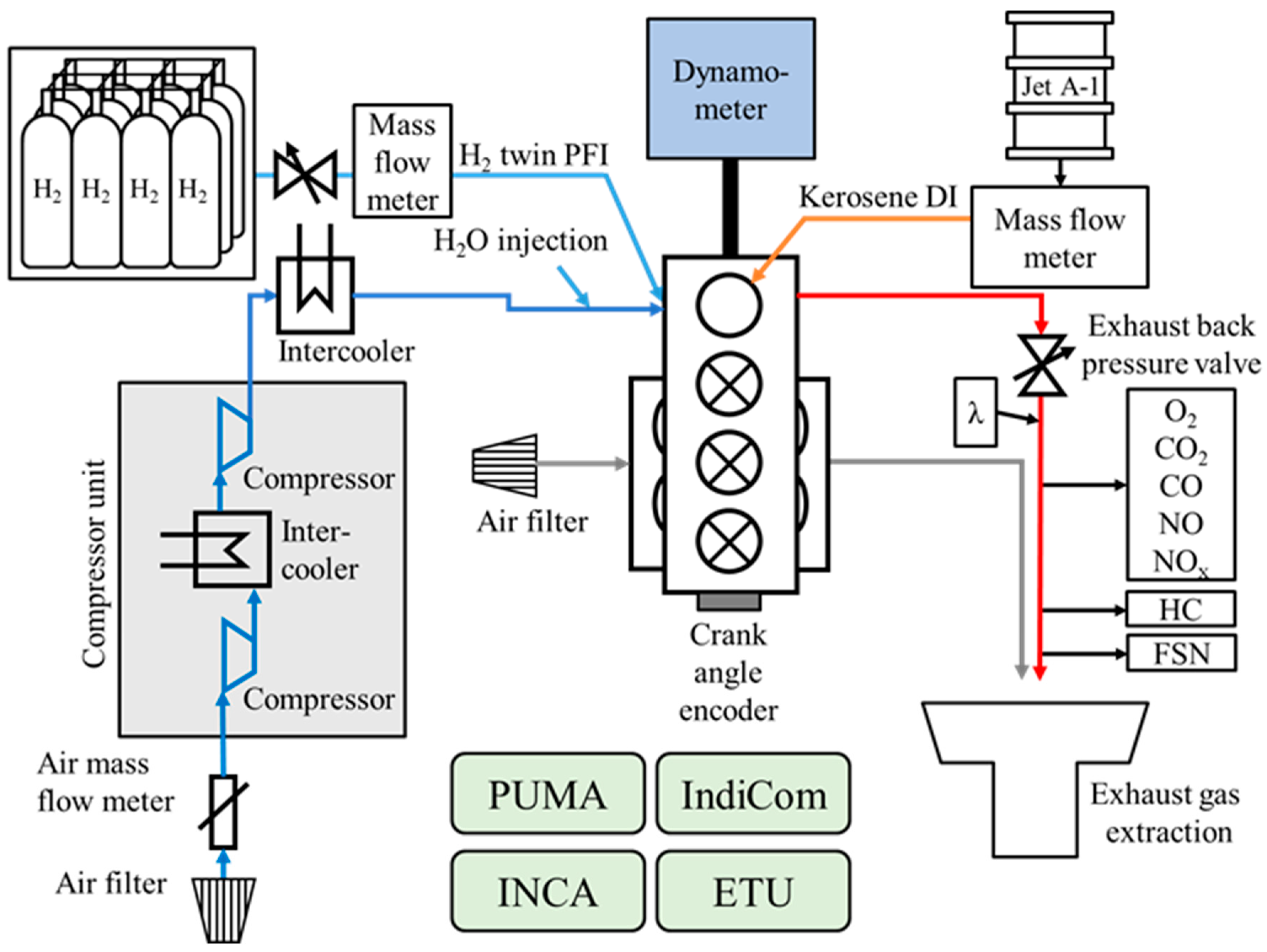
For the purpose of these experiments, the gearbox was removed and the engine was configured for single-cylinder operation. An adapted intake and exhaust manifold, together with a high-inertia flywheel, were installed. Due to insufficient exhaust enthalpy in this setup, the turbocharger was replaced by an external compression system incorporating two Roots superchargers and two intercoolers. An exhaust back-pressure valve was employed to replicate the pressure conditions normally produced by the turbocharger turbine [2].
For in-depth thermodynamic analysis of the combustion process—including the identification of any pre-ignition events—the research engine was equipped with a dedicated cylinder pressure transducer, an absolute intake manifold pressure sensor, and a water-cooled absolute pressure sensor on the exhaust manifold [2].
Additionally, to prevent potential engine damage due to knocking or heavy pre-ignitions in dual-fuel H2 operation during the investigations, a fuel-cut-off device was installed. If a defined, critical in-cylinder pressure is exceeded, a relay interrupts the electric control signal for the hydrogen injectors, immediately cutting of the hydrogen fuel supply to the engine.
In dual-fuel mode, sufficient hydrogen supply at high loads was achieved through a twin-port injection system. The intake manifold was modified to accommodate two hydrogen injectors—one for the charge port and one for the swirl port—with identical control signals. A dedicated hydrogen rail, operating at 1.3 MPa and equipped with a thermocouple and pressure sensor, facilitated fuel monitoring. The injection timing and duration for both hydrogen injectors were managed by an Engine Timing Unit (ETU) [2].
Equation (2) provides the method for determining the hydrogen energy share. According to Rachner [22], the lower heating value (LHV) of ASTM-D1655–certified kerosene (Jet A-1) was taken as 43.26 MJ/kg, while hydrogen was assumed to have an LHV of 120 MJ/kg [23]. Table 2 presents additional key properties for kerosene and hydrogen, along with diesel listed for comparative purposes in dual-fuel applications [2].
x H 2 = m ˙ H 2 L H V H 2 m ˙ H 2 L H V H 2 + m ˙ K e r o s e n e L H V K e r o s e n e
x H 2 Hydrogen energy share[-]
m ˙ H 2 Hydrogen mass flow[kg/h]
L H V H 2 Lower heating value of hydrogen[MJ/kg]
m ˙ K e r o s e n e Kerosene mass flow[kg/h]
L H V K e r o s e n e Lower heating value of kerosene[MJ/kg]
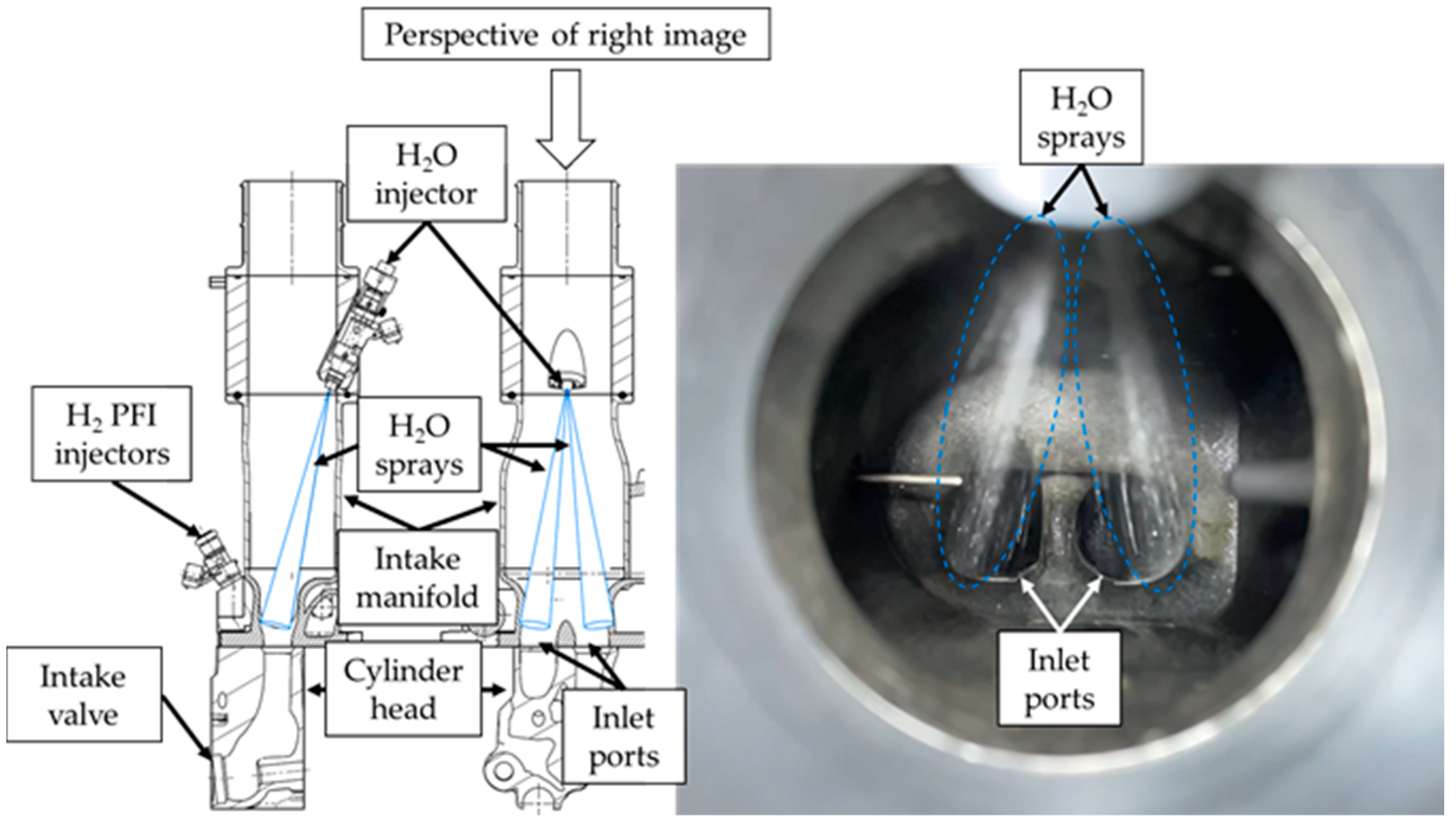
The injector used for water injection was a Bosch Motorsport EV14 injector (0 280 158 117). The slightly angled-‘down’ dual-cone spray pattern enabled precise and uniform distribution across the two inlet ports, resulting in minimized wall wetting and the efficient transportation of water into the combustion chamber. A CAD drawing of the WI-setup as well as a picture of the injected water into the inlet ports is shown in Figure 2. Distilled water was used to prevent limescale deposits and blockages.
Additionally, soot emissions in the exhaust gas were quantified using the Filter Smoke Number (FSN) and monitored with a smoke meter.
A schematic overview of the engine test bench on which the investigations were carried out is presented in Figure 3.

2.2. Tested Oil Candidates

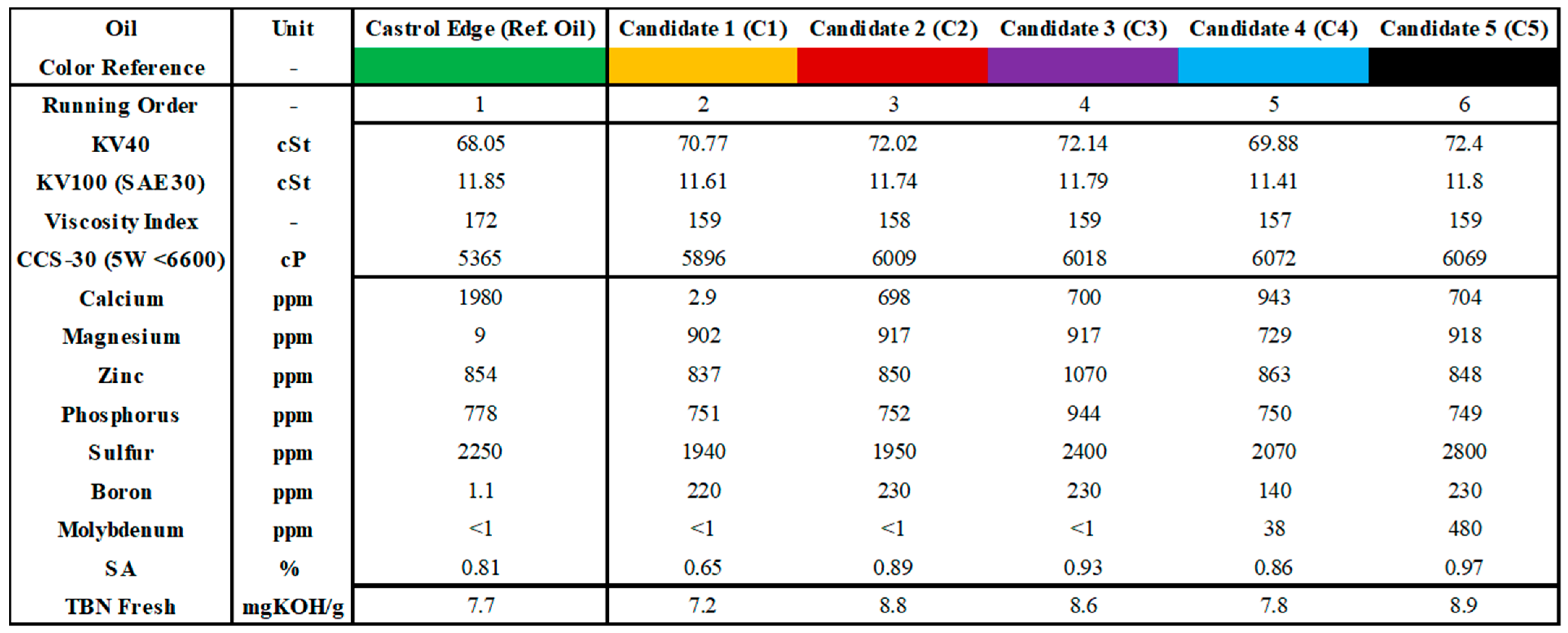
Initially, for the development of the measurement methodology, the standard Austro Engine AE330 lubricant, Liqui Moly Leichtlauf High Tech 5W-40, was used. Subsequently, the reference oil, Castrol Edge 5W-30 C3, along with the test candidates (C1–C5) provided by BP p.l.c., were employed for the investigations. These lubricants and their respective typical properties are summarized in Figure 4. The running order was carefully selected to minimize carryover between oils by testing similar oils consecutively. All tested oils had a viscosity grade of 5W-30, resulting in similar viscosity-related characteristics, such as the kinematic viscosity (KV), viscosity index (VI), and cold-cranking simulator viscosity (CCS).
The detergent content showed a wide range, with calcium varying from 2.9 ppm (C1) to 1980 ppm (reference oil), and magnesium ranging from 9 ppm (reference oil) to 918 ppm (C5). Zinc and phosphorus levels were consistent across the oils, while sulfur (1940–2800 ppm), boron (1.1–230 ppm), and molybdenum (<1–480 ppm) contents showed notable differences. Additionally, the sulfate ash (SA) content varied from a minimum of 0.65 in C1 to a maximum of 0.97 in C5. Lastly, the total base number (TBN) ranged between 7.2 (C1) and 8.9 (C5).

2.3. Flushing Procedure

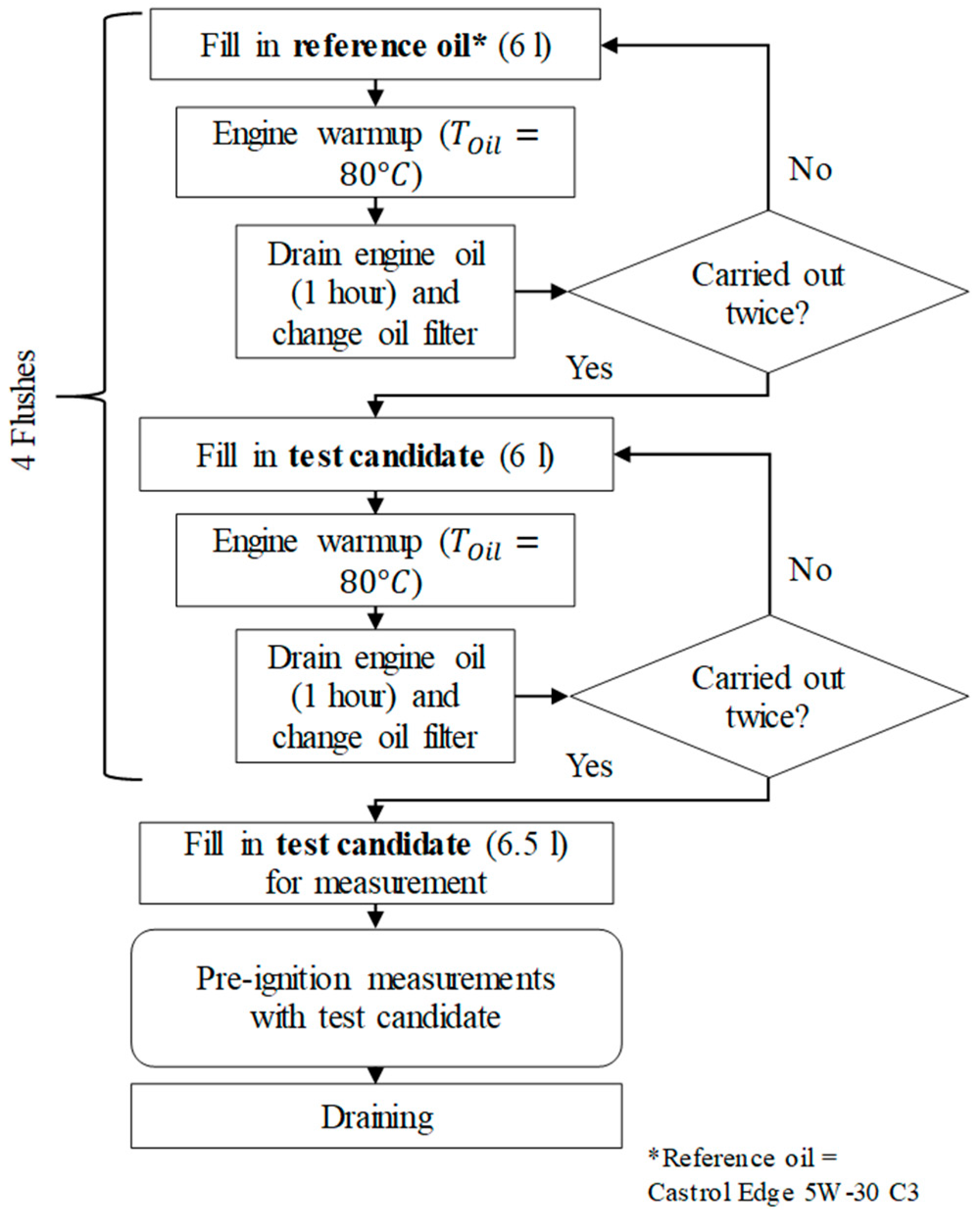
To minimize contamination between the lubricants, a thorough flushing procedure was developed. A flow chart outlining this procedure is presented in Figure 5.
Initially, the flushing procedure was performed twice with the reference oil to establish a consistent baseline and ensure uniform carryover. After the oil fill, the engine was warmed by operation to an oil temperature of 80 °C, promoting thorough mixing and effective flushing due to the reduced oil viscosity. The oil was then drained for one hour, and the oil filter was replaced each time.
Subsequently, the engine was flushed twice with the test candidate to minimize carryover and contamination. Finally, the test candidate was filled, and pre-ignition measurements were conducted.

2.4. Pre-Ignition Detection

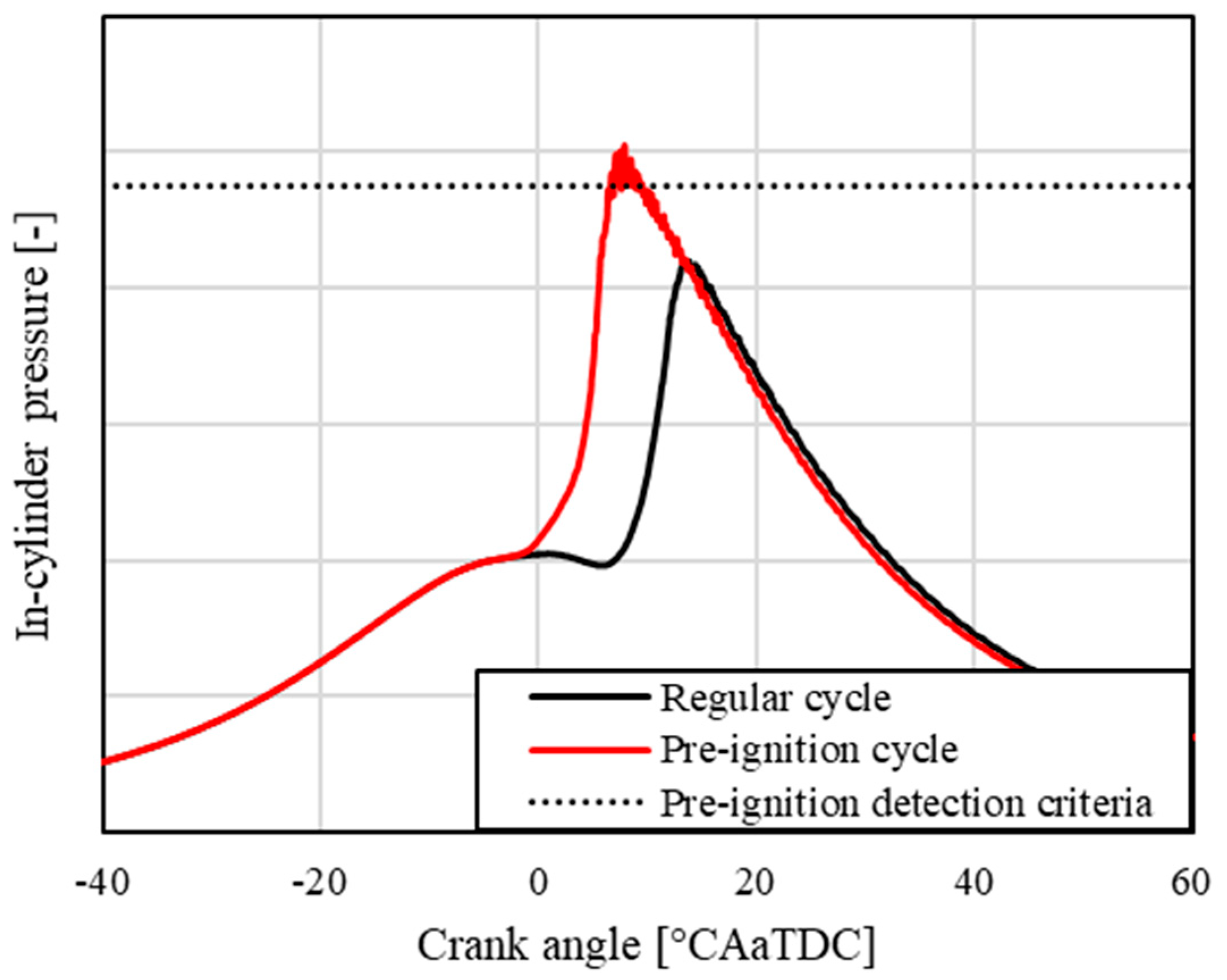
For the detection of pre-ignitions, a well-established method from the literature, such as that in [9,24], was selected. In this case, the criterion was based on the measured peak pressure in the combustion chamber (PMAX). The corresponding calculation is shown in Equation (3). The limit was determined using the mean value of the peak pressures ( x ¯ ) and the standard deviation ( σ ), with a factor of 3 applied to account for process-related cyclic variations. According to the formula, any cycle with a peak pressure above the calculated limit was classified as a pre-ignition event [9].
P M A X L i m i t x ¯ + 3 · σ
P M A X L i m i t Peak pressure limit for PI detection[MPa]
x ¯ Mean value of peak pressures[MPa]
σ Standard deviation of peak pressures[MPa]
Figure 6 provides an example of pre-ignition detection, comparing a pre-ignition cycle (red) and a regular cycle (black) as a reference.

2.5. Test Procedure

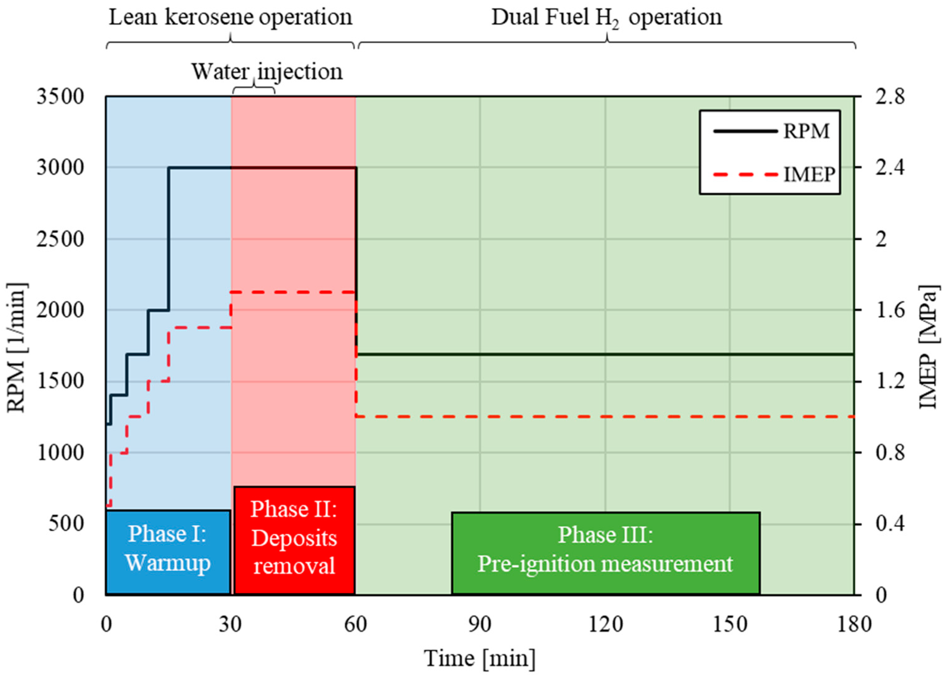
The test procedure is based on the literature [9] and includes several adaptations to improve its suitability for the dual-fuel hydrogen–kerosene combustion process. The entire test cycle lasts approximately three hours and consists of three main phases, which were kept consistent throughout the investigations. The test cycle was conducted five times consecutively to establish a conclusive baseline for the reference oil and twice for each candidate oil to validate the results and stability.
To minimize potential cross-influence from particles and deposits, the following measures were implemented:
  • Addition of a high-load phase (Phase II) to remove deposits in the combustion chamber prior to the measurement phase (Phase III);
  • Lean kerosene operation during Phase I and Phase II ( λ = 2 , resulting in F S N < 0.1 );
  • Water injection during the first ten minutes of Phase II to remove particles and deposits in the intake ports and on the intake valves;
  • Full opening of the exhaust pressure valve in all phases to reduce internal exhaust gas recirculation (EGR), which contributes to increased soot formation;
  • High H2 energy share (70%) in Phase III to minimize soot formation during measurement ( F S N 0.1 ).
The complete test cycle, along with its phases, is illustrated in Figure 7 and explained in detail below.
The first phase is the engine warm-up, with the main goal of achieving a steady-state operating temperature, following a defined pattern. Due to the nature of single-cylinder operation, this phase lasts approximately 30 min.
Once stable coolant and oil temperatures are reached, the second phase begins. This 30 min phase involves high revolutions per minute (RPM), a high indicated mean effective pressure (IMEP), and advanced combustion phasing, which result in elevated in-cylinder pressures and temperatures, effectively removing potential deposits in the combustion chamber. Additionally, water injection, located in the intake manifold, is activated during the first ten minutes to remove possible deposits in the intake ports and on the intake valves caused by residual gas backflow when the intake valves open.
Finally, the third phase consists of two hours of pre-ignition measurement, equating to over 100,000 cycles, during dual-fuel hydrogen–kerosene operation. The engine is operated at 1690 RPM, 1 MPa IMEP, and a hydrogen energy share of 70%, representing the maximum possible hydrogen energy share at this operating point before knocking occurs. The intake manifold pressure is maintained with a deviation of ±0.2 kPa.
All measurements were conducted under stable conditions with a controlled coolant temperature of 79 °C, resulting in an oil temperature of 81 °C, ensuring consistent oil behavior, which may vary under different environmental conditions. Additionally, the intake manifold temperature was regulated to 25 °C. The test bench environment was maintained at an ambient temperature of 23 °C with 50% relative humidity. To account for atmospheric pressure variations throughout the test period, the intake manifold pressure was regulated to a constant value, with a maximum deviation of ±0.2 kPa.
To verify repeatability and validate the developed methodology, five consecutive measurement cycles were conducted with the reference oil, yielding 13 ± 3 (mean ± standard deviation) pre-ignition events, demonstrating good reproducibility compared to the results of similar studies in the literature, e.g., [25].

3. Results

Section 3 presents the findings on flushing efficiency, the performance of tested lubricants in relation to pre-ignition, and the effects of particle-induced pre-ignition.

3.1. Flushing Efficiency

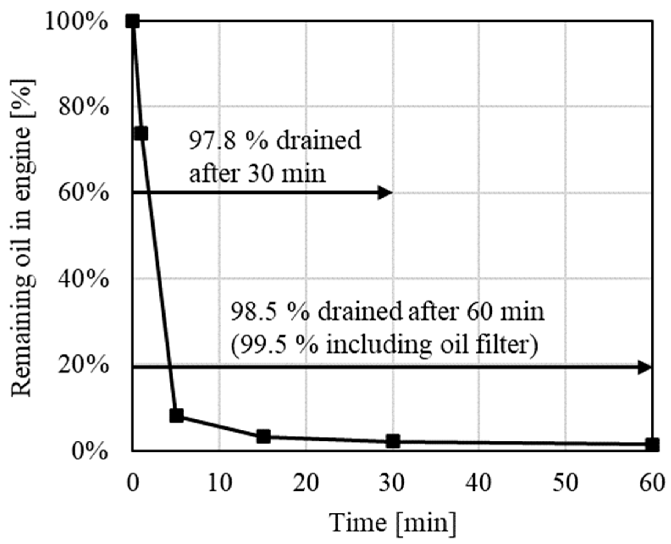
The flushing procedure was validated by measuring both the weight of the oil introduced into the drained engine and the weight of the oil drained after intervals of 1 min, 5 min, 15 min, 30 min, and 60 min, using a digital scale with a precision and accuracy of 1 g. The results are illustrated in Figure 8. The measurements indicate that after 30 min of draining at an initial oil temperature of 80 °C, 97.8% of the input oil mass was removed. After 60 min, this value increased to 98.5%. Accounting for the oil remaining in the filter, which retained approximately 1% of the oil, a total of 99.5% of the input mass was ultimately recovered.
With a resulting flushing efficiency of 99.5%, the contamination level after four consecutive flushes is expected to be negligible. However, this method only considers the mass of the oil added and drained, without accounting for, e.g., oil consumption or dilution during engine operation. Therefore, further analyses using laboratory equipment are necessary to accurately determine the actual contamination levels post-experiment.
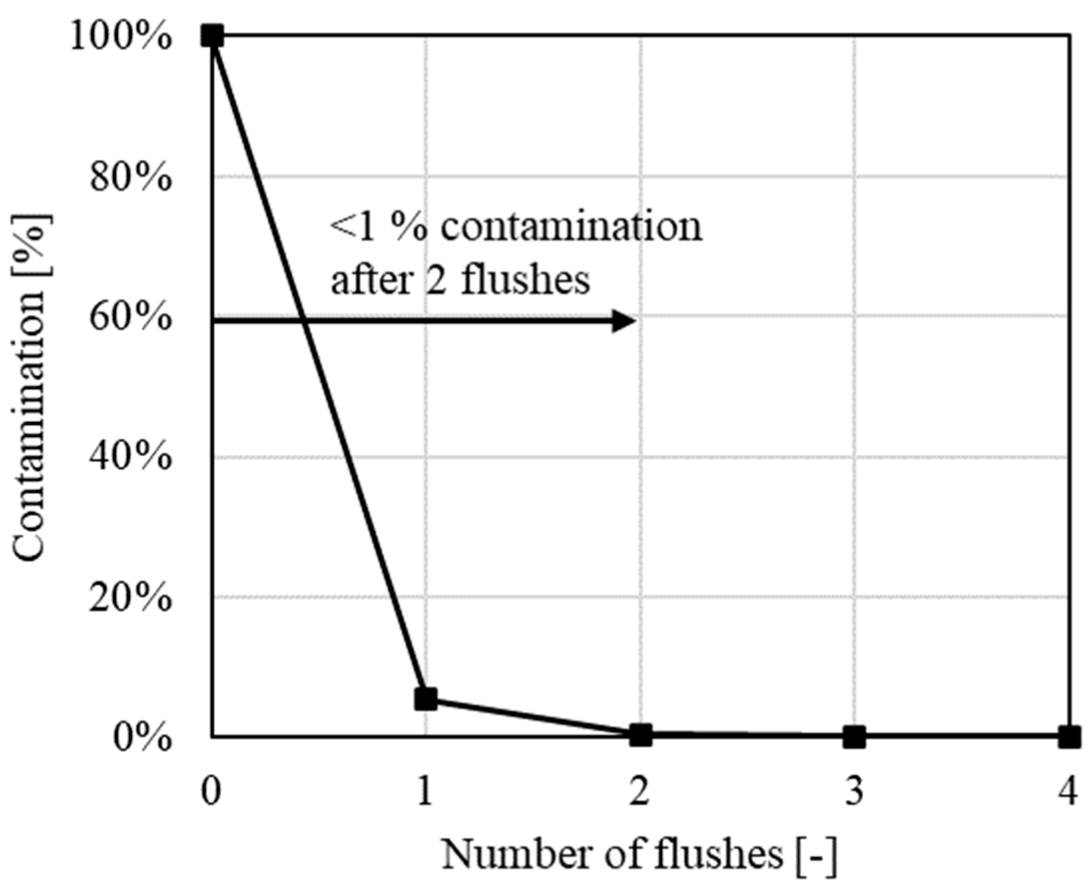
Figure 9 illustrates the oil contamination level during the flushing procedure, plotted over the individual flush cycles, based on laboratory analysis. Samples were taken during the transition from Candidate 5 to the reference oil, and the oil composition was subsequently examined. The magnesium content was used as a key indicator due to its particularly high concentration difference between the two oils, ensuring a reliable and precise assessment of contamination levels. The results indicate that after one flush, the contamination level amounted to 5%, decreasing further to just 0.5% after two consecutive flushes. After the third and fourth flushes, contamination was negligible (<0.1%), providing a reliable foundation for the pre-ignition investigations.

3.2. Oil

Figure 10 presents the overall results of the oil-induced pre-ignition measurements. As is shown, the first three candidates fall within the standard deviation of the reference oil, indicating no significant impact on pre-ignition behavior.
In contrast, the fourth test oil (Candidate 4) demonstrated a notable improvement, showing a marked reduction in the number of pre-ignitions. The frequency of pre-ignition events decreased from an average of 13 instances per measurement with the reference oil to four instances with Candidate 4. An intermediate measurement was conducted using the reference oil, followed by a re-test with Candidate 4 to confirm the observed results.
The investigation revealed that Candidate 5 yielded the most favorable outcomes, with an average of only 1.5 pre-ignitions recorded over the test cycles. A final measurement with the reference oil further validated these findings, confirming that the test setup remained stable throughout the test series.
The main additives that showed the most significant differences between the oils and are renowned for having a considerable impact on the pre-ignition tendency, particularly in turbocharged, downsized gasoline engines, are discussed in detail below.
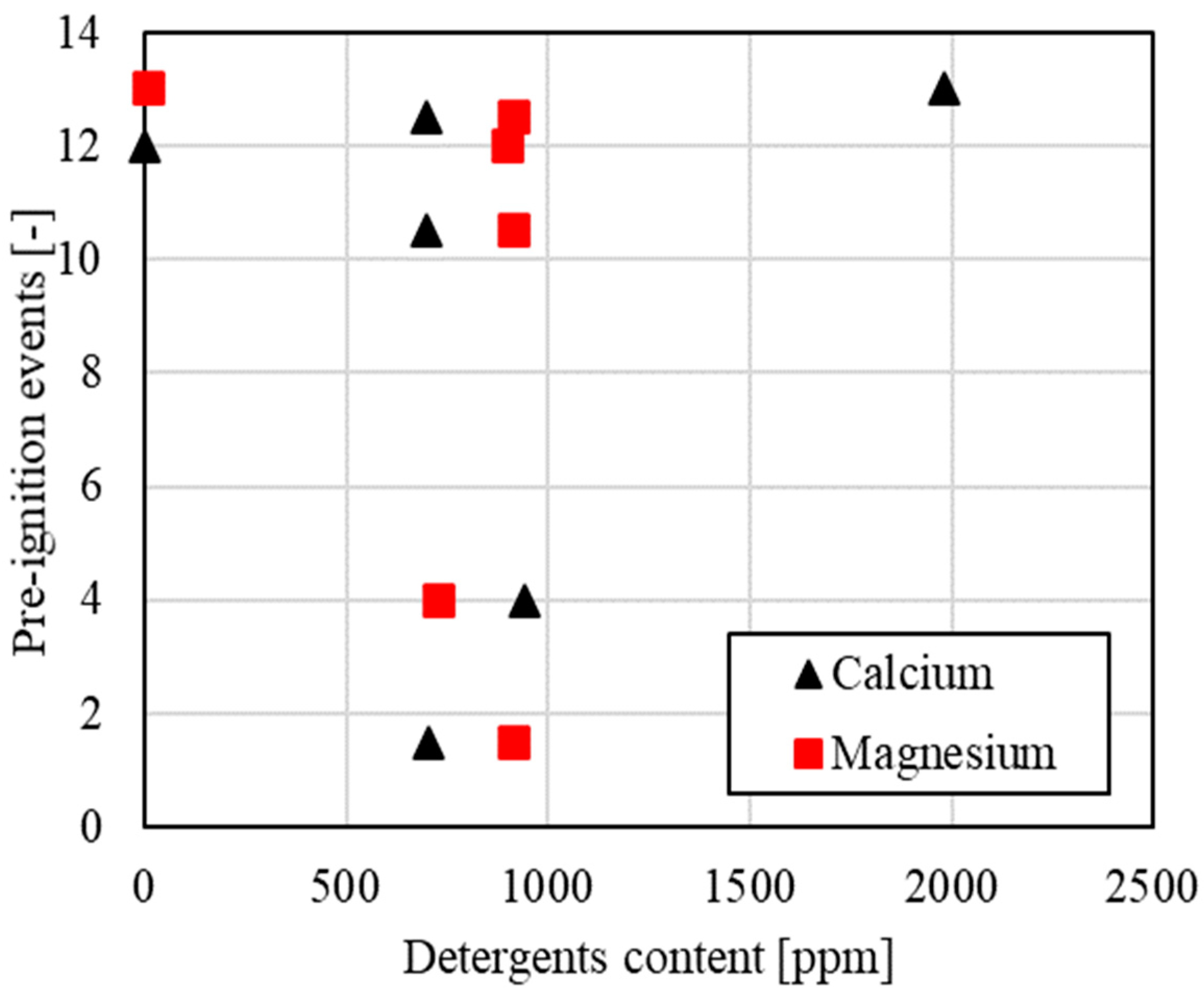
Figure 11 presents the impact of detergent content, calcium, and magnesium, on the number of pre-ignitions. Contrary to expectations and reports in the literature (e.g., [19]) as well as the mentioned findings in gasolines engines, neither the calcium nor the magnesium contents of the engine oil showed a statistically significant influence on the occurrence of pre-ignitions. In accordance with the CaO theory [14], this phenomenon may be attributed to the diminished CO2 content in the residual gas resulting from hydrogen combustion compared to gasoline engines. Since CO2 is a necessary reactant for the exothermic reaction of CaO to CaCO3 (>1000 K), the lack of sufficient CO2 may limit this reaction, thus reducing calcium-related pre-ignition. In addition, the particularly low minimum ignition energy of hydrogen suggests that hot spots caused by CaO particles may not be the primary cause of pre-ignition. In this context, Gschiel et al. also demonstrated that a higher calcium content in the lubricant does not increase the number of pre-ignition events in H2-ICEs [7].
In gasoline engines, magnesium is regarded as a favorable substitute for calcium, with the potential to effectively reduce pre-ignitions, as supported by the literature (e.g., [9,26]). In principle, even at the low reactant content (CO2), the lower exothermic temperatures of magnesium reactions (ca. 870 K) compared to calcium, as documented in [16], could still exceed the threshold required to ignite the hydrogen–air mixture—especially considering the significantly lower minimum ignition energy of hydrogen compared to gasoline. (0.017 mJ for hydrogen and 0.24 mJ for gasoline, as outlined in [23]). However, there was no trend here either; so, in particular, there is still a need for research into the exact mechanisms of action of calcium and magnesium in the hydrogen engine.
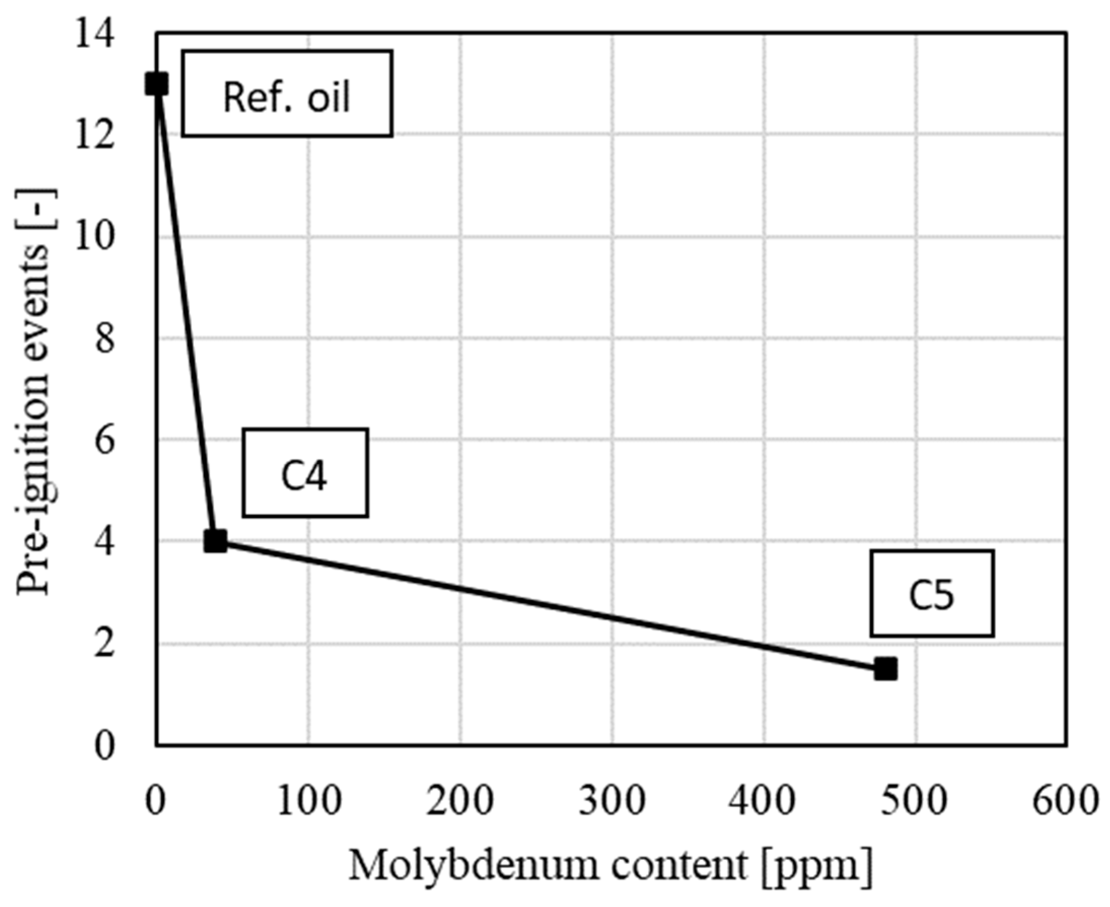
Figure 12 depicts the correlation between the number of pre-ignitions and the molybdenum content of the oil. It appears that the number of pre-ignitions can be significantly reduced with an increase in molybdenum content. The pre-ignitions were reduced from 13 to only 4 events when Candidate 4, containing 38 ppm, was used in comparison to the reference oil. The results showed that Candidate 5, with 480 ppm molybdenum, yielded the most favorable outcomes, with an average of 1.5 pre-ignitions recorded per measurement cycle. Notably, Candidates 1 to 3 contained no measurable molybdenum (<1 ppm). It is plausible that the observed decline can be attributed to the beneficial effects of MoDTC, which include antioxidant properties, acting as a radical scavenger (radical binding) and hydroperoxide decomposer (chain propagation prevention) [13].
The beneficial impact of MoDTC on the pre-ignition tendency in turbocharged, downsized gasoline engines has been well-documented in the existing literature, as supported by exemplary references [9,12,17].

3.3. Particles and Deposits

Following the initial assumption that particles and deposits have a significant impact on the pre-ignition tendency, specific modifications were made to the measurement methodology. This included particle loading under rich conditions (λ = 0.97) in lieu of Phase II, as well as the exclusion of water injection. After the 30 min loading phase, the measurement (Phase III) was conducted as usual.
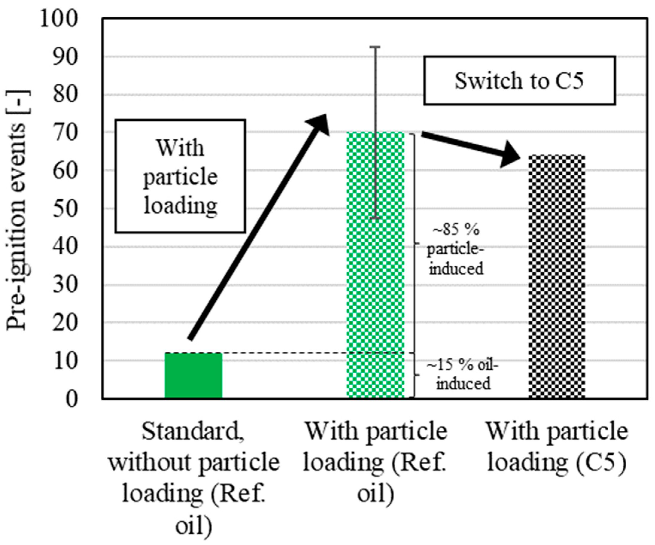
Figure 13 illustrates the pre-ignition events of the standard procedure (left bar) compared to the measurement cycle with particle loading (mid bar), both utilizing the reference oil. It is evident that the number of pre-ignitions increased significantly, rising from approximately 12 without particle loading to 70 with particle loading (averaged over three measurement cycles). This suggests that approximately 15% of the pre-ignitions can be attributed to oil-induced pre-ignitions, while the remaining 85% are likely caused by particle-induced pre-ignitions.
Moreover, the efficacy of Candidate 5 (C5) was evaluated with particle loading (right bar). In this case, the number of pre-ignitions showed a slight decrease, from an average of 70 pre-ignitions with the reference oil to 64 with C5. This suggests that the elevated molybdenum content does not have a significant effect on particle-induced pre-ignitions.

4. Conclusions and Outlook

Abnormal combustion, such as pre-ignition, presents a critical challenge in the development of hydrogen internal combustion engines. While many authors have explored methods to reduce pre-ignitions, such as water injection, there is a notable gap in research concerning the origins of pre-ignition, particularly in relation to engine oil. For this reason, this paper focuses on the formation of pre-ignition and the influence of various engine oil compositions on the tendency toward pre-ignition.
The key findings of this study can be summarized as follows:
  • By using a test procedure specifically developed for the dual-fuel hydrogen–kerosene engine, pre-ignition events were detected with high accuracy.
  • A detailed purging procedure ensured that contamination between the test oils was minimized, allowing the cross-influences of other oils to be effectively neglected.
  • The investigation of oils with varying detergent contents (calcium and magnesium) revealed that these components had no significant influence on the tendency for pre-ignition.
  • However, it was demonstrated that increasing the molybdenum content significantly reduced the number of pre-ignitions. In fact, the pre-ignition events decreased from 13 with the reference oil, without a molybdenum content, to 4 with 38 ppm of molybdenum (Candidate 4), and to just 1.5 with 480 ppm of molybdenum (Candidate 5).
  • Further investigations into particle-induced pre-ignition, attributed to the unavoidable soot formation in the dual-fuel combustion process, showed that approximately 85% of the pre-ignitions were caused by particles, with only 15% resulting from the oil. This ratio is likely similar in regular dual-fuel hydrogen operation. A comparative measurement with the test oil that exhibited the lowest pre-ignition rate due to its molybdenum content (Candidate 5) showed that the number of pre-ignitions with particle loading could only be slightly reduced.
The presented findings contribute to the current research in terms of reducing pre-ignition events and enhancing hydrogen combustion stability, enabling higher hydrogen energy shares in dual-fuel engines and thereby reducing CO2 emissions. Despite the promising results, further investigations are necessary to evaluate the influence of other oil additives on pre-ignition tendency. In particular, the transferability of these findings to a spark-ignited hydrogen engine should be demonstrated. Additionally, further research on different engine configurations, multi-cylinder engines, operating points, and operating temperatures is recommended to validate the findings of this study.
Regarding particle-induced pre-ignition, previous dual-fuel hydrogen engine studies have already shown that a higher air–fuel ratio offers significant advantages. Not only does it reduce in-cylinder temperatures and particle formation, but it also increases the minimum ignition energy of hydrogen, further reducing the risk of pre-ignition. Furthermore, future studies should focus on particle-induced pre-ignition, particularly the relationship between soot formation and varying engine loads and operating temperatures.

Author Contributions

Conceptualization, C.R.; methodology, C.R. and P.H. (Peter Hofmann); software, C.R.; validation, C.R., P.H. (Peter Hofmann) and P.H. (Paul Howarth); formal analysis, C.R.; investigation, C.R.; resources, C.R., P.H. (Peter Hofmann) and P.H. (Paul Howarth); data curation, C.R.; writing—original draft preparation, C.R.; writing—review and editing, C.R., P.H. (Peter Hofmann) and P.H. (Paul Howarth); visualization, C.R.; supervision, P.H. (Peter Hofmann); project administration, C.R. and P.H. (Peter Hofmann); funding acquisition, P.H. (Peter Hofmann). All authors have read and agreed to the published version of the manuscript.

Funding

This research was funded by the Austrian Research Promotion Agency (FFG), grant number FO999886840.

Data Availability Statement

Confidentiality agreements do not allow the publication of the data presented in this study.

Acknowledgments

We extend our sincere appreciation to the FFG (Austrian Research Promotion Agency) for their financial support as part of the Austrian research funding program “Take Off”. We would also like to acknowledge our project partner, Austro Engine GmbH, for their collaboration and assistance throughout this project. Additionally, we would like to thank BP for providing the engine oils and their support throughout the investigations. We also thank Bosch General Aviation Technology for providing the hydrogen injectors used in this study. The authors acknowledge Open Access Funding by TU Wien Bibliothek for financial support.

Conflicts of Interest

The authors declare no conflict of interest.

Abbreviations

The following abbreviations are used in this manuscript:
CADComputer-aided design
CCSCold-cranking simulator
CO2Carbon dioxide
CaCalcium
CaOCalcium oxide
DIDirect injection
EGRExhaust gas recirculation
FSNFilter smoke number
g/gGram per gram
HEFAHydroprocessed ester and fatty acid
H2Hydrogen
ICEInternal combustion engine
IFAInstitut für Fahrzeugantriebe und Automobiltechnik,
engl.: Institute of Powertrain and Automotive Technology
IMEPIndicated mean effective pressure
KVKinematic viscosity
LHVLower heating value
MgMagnesium
MPaMegapascal
MoDTCMolybdenum dithiocarbamate
PAHPolycyclic aromatic hydrocarbon
PFIPort fuel injection
PIPre-ignition
RPMRevolutions per minute
SASulfate ash
SAFSustainable aviation fuel
TBNTotal base number
VIViscosity index
W/WWatt per watt
λAir–fuel ratio

References

  1. International Council on Clean Transportation. Vision 2050: A strategy to decarbonize the global transport sector by mid-century. White Paper, 21 September 2020; p. 5.
  2. Reitmayr, C.; Wiesmann, F.; Gotthard, T.; Hofmann, P. Experimental and Numerical Investigations of a Dual Fuel Hydrogen-Kerosene Engine for Sustainable General Aviation. SAE Technical Paper 0148-7191, 17 June 2024. [Google Scholar] [CrossRef]
  3. Heywood, J.B. Internal Combustion Engine Fundamentals; McGraw-Hill Education: New York, NY, USA, 2018; ISBN 1260116107. [Google Scholar]
  4. Grabner, P.; Schneider, M.; Gschiel, K. Formation Mechanisms and Characterization of abnormal Combustion Phenomena of Hydrogen Engines. SAE Technical Paper, 29 September 2023; ISBN 0148-7191. [Google Scholar]
  5. Merker, G.P.; Teichmann, R. Grundlagen Verbrennungsmotoren: Funktionsweise und Alternative Antriebssysteme Verbrennung, Messtechnik und Simulation; Springer Fachmedien Wiesbaden: Imprint: Springer Vieweg: Wiesbaden, Germany, 2019. [Google Scholar] [CrossRef]
  6. Nübling, F.; Maulbetsch, T. Development of Dedicated Lubricant Solutions for Hydrogen Combustion Engines. In Proceedings of the 19th Symposium Sustainable Mobility, Graz, Austria, 28–29 September 2023. [Google Scholar]
  7. Gschiel, K.; Wilfling, K.; Schneider, M. Development of a method to investigate the influence of engine oil and its additives on combustion anomalies in hydrogen engines. Automot. Engine Technol. 2024, 9, 3. [Google Scholar] [CrossRef]
  8. Johansson, P. Oil-Related Particle Emissions from Diesel Engines. Bachelor’s Thesis, KTH Industrial Engineering and Management, Stockholm, Sweden, 2008. [Google Scholar]
  9. Mayer, M. Einfluss der Motorölspezifikationen Sowie Unterschiedlicher Kraftstoffeigenschaften auf das Vorentflammungsverhalten von Hochaufgeladenen Direkteinspritzenden Ottomotoren. Ph.D. Thesis, Institute of Powertrains and Automotive Technology, Vienna University of Technology, Vienna, Austria, 2015. [Google Scholar]
  10. Yasueda, S.; Takasaki, K.; Tajima, H. Abnormal combustion caused by lubricating oil in high BMEP gas engines. MTZ Industrial 2013, 3, 34–39. [Google Scholar] [CrossRef]
  11. Ohtomo, M.; Miyagawa, H.; Koike, M.; Yokoo, N.; Nakata, K. Pre-Ignition of Gasoline-Air Mixture Triggered by a Lubricant Oil Droplet. SAE Int. J. Fuels Lubr. 2014, 7, 673–682. [Google Scholar] [CrossRef]
  12. Hirano, S.; Yamashita, M.; Fujimoto, K.; Kato, K. Investigation of engine oil effect on abnormal combustion in turbocharged direct injection-spark ignition engines (Part 2). SAE Technical Paper, 14 October 2013. [Google Scholar]
  13. Mortier, R. Chemistry and Technology of Lubricants; Springer: Berlin/Heidelberg, Germany, 2010. [Google Scholar]
  14. Moriyoshi, Y.; Yamada, T.; Tsunoda, D.; Xie, M.; Kuboyama, T.; Morikawa, K. Numerical simulation to understand the cause and sequence of LSPI phenomena and suggestion of CaO mechanism in highly boosted SI combustion in low speed range. SAE Technical Paper, 14 April 2015. [Google Scholar]
  15. Rönn, K.; Swarts, A.; Kalaskar, V.; Alger, T.; Tripathi, R.; Keskiväli, J.; Kaario, O.; Santasalo-Aarnio, A.; Reitz, R.; Larmi, M. Low-speed pre-ignition and super-knock in boosted spark-ignition engines: A review. Prog. Energy Combust. Sci. 2022, 95, 101064. [Google Scholar] [CrossRef]
  16. Maitra, S.; Chakrabarty, N.; Pramanik, J. Decomposition kinetics of alkaline earth carbonates by integral approximation method. Cerâmica 2008, 54, 268–272. [Google Scholar] [CrossRef]
  17. Takeuchi, K.; Fujimoto, K.; Hirano, S.; Yamashita, M. Investigation of Engine Oil Effect on Abnormal Combustion in Turbocharged Direct Injection - Spark Ignition Engines. SAE Int. J. Fuels Lubr. 2012, 5, 1017–1024. [Google Scholar] [CrossRef]
  18. De Feo, M.; Chaillou, C.; Laigle, E.; Lurf, G.; Kunder, N.J.; Wieser, M.; Wilfling, K.; Schneider, M.; Torkelson, J. The Role of Lubricant Formulation in Controlling Pre-Ignition Phenomena in a H2-ICE. In Proceedings of the 45th International Vienna Motor Symposium, Vienna, Austria, 24–26 April 2024. [Google Scholar]
  19. Golisano, R.; Scalabrini, S.; Arpaia, A.; Pesce, F.; Vassallo, A.; Borgia, L.; Cubito, C.; Biasin, V.; Knichel, T.; Millo, F.; et al. “PUNCH Hydrogen internal combustion engine & KERS: An appealing value-proposition for green power pack. In Proceedings of the Proceedings of the 42nd International Vienna Motor Symposium, Vienna, Austria, 29–30 April 2021. [Google Scholar]
  20. Okada, Y.; Miyashita, S.; Izumi, Y.; Hayakawa, Y. Study of Low-Speed Pre-Ignition in Boosted Spark Ignition Engine. SAE Int. J. Engines 2014, 7, 584–594. [Google Scholar] [CrossRef]
  21. Diamond Aircraft. Engine Specifications. Available online: https://www.diamondaircraft.com/en/austro-engine/e4-series/overview/ (accessed on 18 January 2024).
  22. Rachner, M. Die Stoffeigenschaften von Kerosin Jet A-1. Available online: https://elib.dlr.de/3185/1/Kerosene-Properties_Rachner_%20DLR-Mitteilung-98-01%2BErrata.pdf (accessed on 15 March 2025).
  23. Klell, M.; Eichlseder, H.; Trattner, A. Hydrogen in Automotive Engineering; Springer Nature: Dordrecht, The Netherlands, 2023. [Google Scholar] [CrossRef]
  24. Luef, R. Entwicklung einer Prüfmethode zur Bestimmung des Öleinflusses auf Irreguläre Verbrennungsphänomene bei Hochaufgeladenen DI-Ottomotoren. Ph.D. Thesis, Institute of Thermodynamics and Sustainable Propulsion Systems, Graz University of Technology, Graz, Austria, 2015. [Google Scholar]
  25. Mayer, M.; Hofmann, P.; Williams, J.; Tong, D. Vorentflammungseinfluss des Motoröls bei hochaufgeladenen Ottomotoren mit direkter Einspritzung. MTZ-Mot. Z. 2016, 77, 42–47. [Google Scholar] [CrossRef]
  26. Ritchie, A.; Boese, D.; Young, A.W. Controlling Low-Speed Pre-Ignition in Modern Automotive Equipment Part 3: Identification of Key Additive Component Types and Other Lubricant Composition Effects on Low-Speed Pre-Ignition. SAE Int. J. Engines 2016, 9, 832–840. [Google Scholar] [CrossRef]
Figure 1. Types of abnormal combustion: (a) pre-ignition; (b) runaway surface ignition; (c) pre-ignition with knocking.
Lubricants 13 00126 g001
Figure 2. CAD drawing of the water injection showing the dual spray pattern (left) and a picture of the actual water injection into the intake ports (right).
Lubricants 13 00126 g002
Figure 3. Schematic overview of the engine test bench setup.
Lubricants 13 00126 g003
Figure 4. Table presenting the typical properties of the varied additives in the reference oil and the five investigated oil candidates, highlighting major differences in key additives such as calcium, magnesium, and molybdenum across the lineup.
Lubricants 13 00126 g004
Figure 5. Flushing procedure of the lubricants.
Lubricants 13 00126 g005
Figure 6. In-cylinder pressure versus crank angle with a regular cycle (black) and a pre-ignition cycle (red), illustrating the pre-ignition detection criteria.
Lubricants 13 00126 g006
Figure 7. RPM and IMEP as a function of time, presenting the three phases of the developed oil-induced pre-ignition measurement cycle for a dual-fuel kerosene H2 engine. Phase I: warm-up; Phase II: deposit removal; Phase III: pre-ignition measurement.
Lubricants 13 00126 g007
Figure 8. Remaining oil in engine over time, showing the drained oil after 30 min and after 60 min, indicating that 99.5% of the introduced oil mass could be drained after a 60 min drain including an oil filter change.
Lubricants 13 00126 g008
Figure 9. Oil contamination as measured magnesium content during the flushing procedure vs. the number of the flushes according to laboratory analyses, showing negligible contamination of only 2 flushes (4 flushes were carried out in the course of these investigations).
Lubricants 13 00126 g009
Figure 10. Results of the measurements regarding oil-induced pre-ignitions of the five test candidates as well as the reference oil as a baseline and for verification.
Lubricants 13 00126 g010
Figure 11. Number of pre-ignition events as a function of the detergent contents (calcium and magnesium).
Lubricants 13 00126 g011
Figure 12. Number of pre-ignition events as a function of the molybdenum content.
Lubricants 13 00126 g012
Figure 13. Influence of particle loading on the number of pre-ignition events. Comparison of standard measurement (without particle loading) and particle loading using reference oil and C5, respectively.
Lubricants 13 00126 g013
Table 1. Specifications of the research engine [21].
SpecificationAustro Engine AE330
Max. Take-Off Power132 kW
Displacement1991 cm3
Weight (dry)186 kg incl. gearbox
FuelKerosene (Jet A-1)
Fuel Consumption39 l/h at 100% power
Fuel Consumption21 l/h at 60% power
Compression Ratio17.5:1
InjectionCommon Rail Direct Injection
Table 2. Fuel properties for the kerosene and hydrogen used are derived from [22,23], with diesel from [23] included for comparison.
ParameterUnitDieselKeroseneHydrogen (Gaseous)
Cetane number-52–5443 *-
Densitykg/m3820–845775–8400.09
Lower heating valueMJ/kg42.943.26120
Stoichiometric air requirementkgAir/kgFuel14.714.6734.3
Molar massg/mol190167.32.016
Minimum ignition energymJ0.24-0.017
Ignition limitsλ-Range1.35–0.48-10–0.13
Laminar flame speedcm/s40-230
* Determined in-house.
Disclaimer/Publisher’s Note: The statements, opinions and data contained in all publications are solely those of the individual author(s) and contributor(s) and not of MDPI and/or the editor(s). MDPI and/or the editor(s) disclaim responsibility for any injury to people or property resulting from any ideas, methods, instructions or products referred to in the content.