1. Introduction
Hydrodynamic bearing-supported turbochargers have become very popular in internal combustion engines, especially due to the ever-stricter emission standards of our time [
1,
2,
3]. However, as internal combustion engine technology advances, it has imposed increased mechanical and thermal stress on the essential core assembly of turbochargers. Consequently, the need for a detailed exploration and understanding of rotordynamic phenomena has surged in importance. This realm of research has become indispensable in optimizing the lifespan of turbocharger development.
Turbochargers are capable of reaching extremely high rotational speeds, causing the rotor shaft to exhibit flexibility. This flexibility during rotation triggers a variety of bending modes of the shaft, which can exert inter-related influences on the bearings and the lubrication conditions during the whole range of rotational speeds [
4,
5,
6,
7].
The lubricant film in turbochargers is crucial for maintaining rotor stability and reducing wear between the bearings and shaft. Its thickness and viscosity are essential for bearing performance, particularly at high speeds where the film prevents metal-to-metal contact. However, the exact behavior of the lubricant film under varying conditions, such as temperature and pressure changes, is not fully described. Current models struggle to capture the complex interactions between the lubricant, bearing surface, and rotor.
Several studies have examined the influence of lubricant supply parameters on turbocharger performance [
8,
9,
10,
11,
12].
Rotor systems operating at high rotational speeds often exhibit nonlinear behavior due to the complex interplay of various factors. These time-dependent variables include bearing clearance, oil-film thickness, fluid-dynamic effects, stiffness, damping parameters, and other mechanical influences, all of which affect system dynamics. Shaw et al. [
13] discussed how oil-film forces and mechanical phenomena, such as unbalanced mass and rotor rigidity, contribute to these nonlinear effects. The fluid forces can be derived by solving Reynolds’ equation, with hydrodynamic forces calculated by integrating the pressure distribution in both radial and tangential directions. Advanced mathematical methods, such as the Hopf bifurcation theory, have been applied to calculate stability boundaries and determine stability diagrams for further investigation [
14].
Hopf bifurcation, particularly first-order Hopf bifurcation, has been extensively studied in rotor dynamics. Sri et al. [
15] expanded this research by focusing on secondary Hopf bifurcations, especially in the context of resonance. Their study highlighted the occurrence of superharmonic and subharmonic vibrations, as well as the role of hysteresis and bifurcation phenomena, which are particularly relevant when comparing ramp-up run (RUR) and ramp-down run (RDR) differences. These differences can provide critical insights into the transient behavior of rotor systems and the occurrence of self-excited vibrations.
Choi et al. [
16] outlined a new algorithm that simplifies nonlinear dynamic systems by reducing their dimensionality, making it easier to detect periodic solutions. In their subsequent work, Choi et al. [
17] applied this method to a piecewise oscillator subjected to multi-frequency excitation, identifying bifurcation thresholds and obtaining torus solutions. These approaches have proven effective in analyzing bifurcation points and instability thresholds, aiding in the control of self-excited vibrations during transient processes in both RUR and RDR.
Muszynska’s [
18] research took a non-algorithmic analytic approach to explain transitions to limit cycles and instability thresholds, more commonly referred to as hysteresis, a term introduced by Adams and Guo [
19]. Muszynska’s work separated the instability threshold into real and imaginary components, supported by analytical calculations. Additionally, she introduced the concept of the unwinding spiral orbit, describing the circular motion of the rotor, and used this framework to analyze amplitude and frequency domains. Her theories have been adapted into experimental settings, especially for turbomachinery, where hysteresis is studied in relation to varying lubricant properties [
18].
Chauvin [
20] developed a simple turbomachinery test rig consisting of a lightly loaded rotor with identical plain journal bearings on either side. This setup allowed for further analysis using Automated Diagnostic for Rotating Equipment (ADRE), and was later employed in advanced hysteresis studies, where changes in lubricant properties were correlated with hysteresis behavior. Wang et al. [
21] expanded on this work by presenting a detailed investigation into how variations in lubricant properties affect hysteresis, utilizing both algorithmic methods and Hopf bifurcation theory. Hopf bifurcations in rotor systems can also give rise to chaotic vibration effects, as discussed by Tsuyoshi et al. [
22]. They demonstrated that Hopf bifurcations and consecutive period-doubling bifurcations can lead to chaos, often triggered by harmonic resonance at twice the main critical speed. Their work also showed that chaotic vibrations can occur in rotor systems with small gyroscopic moments and weak nonlinearity.
Another important aspect of rotordynamic analysis is eccentricity, which has gained considerable attention in the study of resonance and hysteresis. Eccentricity, like other properties such as dynamic–static force ratio and non-dimensional frequency, impacts system stability. Brown et al. [
23] investigated the effects of operating eccentricity, using analytical methods and bifurcation theorems to demonstrate how these factors influence the system’s stability and bifurcation behavior.
Their results showed that Fourier frequency spectra and Poincaré map plots [
24] can confirm the aperiodic nature of chaotic behavior of rotor systems, providing a comprehensive framework for understanding the dynamic response of such systems under varying conditions.
The hysteresis phenomenon has been investigated in multiple recent studies [
25,
26,
27]. However, while both bolted joint hysteresis and rotordynamic hysteresis involve hysteresis and energy dissipation, their underlying mechanisms are fundamentally different. Bolted joint hysteresis arises as a contact phenomenon, whereas rotordynamic hysteresis is a system-level dynamic phenomenon. This article focuses specifically on rotordynamic system-related hysteresis, exploring its effects within the context of turbocharger dynamics and lubricant properties.
A comprehensive study was conducted by Vistamehr [
28], in which nonlinear predictions were made to investigate the two subsynchronous whirl frequencies of a turbocharger supported by a semi-floating ring bearing. The results summarize various cases such as reduced pressure, altered temperature, and changes in bearing film length, along with their effects on the two subsynchronous frequencies and the bifurcation speeds. Furthermore, the study introduces a new perspective on the internal and combined relationships between these parameters. This paper presents an experimental study using a high-speed turbocharger test bench to investigate hysteresis phenomena in the subsynchronous frequency range during run-up and run-down cycles. Supported by analytical methods and bifurcation theorems, the study provides insights into the nonlinear interactions between lubrication properties, rotor dynamics, and subsynchronous vibrations. Key factors such as oil viscosity, temperature, and bifurcation points are examined to determine their influence on hysteresis width and subsynchronous components, offering a deeper understanding of rotordynamic stability.
The study also explores frequency jumps occurring at specific bifurcation speeds, attributed to changes in rotor mode shapes that significantly alter system behavior. Bifurcation phenomena and the resulting abrupt transitions in vibrational response as the rotor moves through critical speeds are analyzed in detail. The impact of lubricant type, oil inlet temperature, and their combined effect on hysteresis magnitude and bifurcation points are emphasized as central to understanding system stability. These findings contribute to the key insight that vibration sensors could provide real-time feedback on oil supply conditions, offering potential enhancements for turbochargers and other rotating machinery.
Using four synthetic lubricants tested at various oil inlet temperatures, the experimental findings are further supported by statistical methods to quantify the dynamic response, providing a framework for optimizing turbocharger performance under transient operating conditions.
2. Materials and Methods
The preparation, execution, and analysis of the experimental measurements encompass multiple critical aspects. Accordingly, this section provides a detailed overview of the test environment, the experimental procedure, and the data evaluation methodology.
2.1. Testing Environment
A specialized turbocharger component test bench, designed specifically for vibration diagnostics, was used to conduct the experiments (see
Figure 1). A turbocharger of a 4-cylinder gasoline engine was powered by pressurized air generated by a belt-driven centrifugal compressor (Rotrex C38, Rotrex, Copenhagen, Denmark). The control system (NI CompactRIO) of the test bench enabled standardized tests with a predetermined turbocharger ramp-up rate. A uniquely designed oil conditioning unit provided lubrication to the turbocharger. The precise control over the oil conditioning unit was crucial for studying the impact of varying oil properties on turbocharger vibrations. The unit allowed for oil pressure adjustments and also oil inlet temperature control, therefore fully encompassing the operating conditions encountered in real-world environments.
To measure turbocharger vibrations, IMC (AD1E060, imc, Berlin, Germany) one-directional acceleration sensors ((1) on
Figure 1) were mounted on an adapter in three directions and attached directly to the bearing housing. A Picoturn (PTSM-H 5.3, Picoturn, Cambridgeshire, UK) eddy-current type rotational speed sensor ((2) on
Figure 1) was used to monitor rotor speed. An IMC Cronosflex (CRFX-2000 GP, imc, Berlin, Germany) data acquisition system, with a sampling frequency set to 50 kHz per channel, processed the signals from both the speed sensor and acceleration sensors, making it well-suited for vibration analysis.
2.2. Experimental Procedure
The experiment involved standardized turbocharger ramp-up and ramp-down tests to investigate the influence of lubricant viscosity on turbocharger vibrations. Four commonly used automotive lubricants—SAE 0W-20, SAE 0W-30, SAE 5W-30, and SAE 5W-40—were selected. These lubricants were chosen to ensure variation in both cold and high-temperature viscosity, facilitating a comprehensive analysis of how viscosity changes affect the turbocharger’s dynamic behavior.
Table 1 summarizes the density and viscosity values for the applied lubricants.
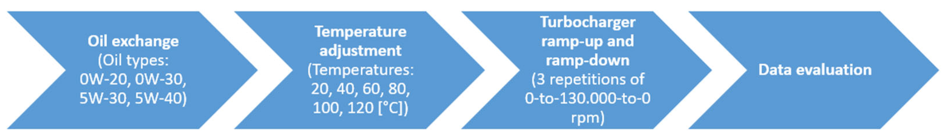
The test procedure was designed to systematically evaluate the effects of oil inlet temperature on the turbocharger’s dynamic behavior. Each oil type (0W-20, 0W-30, 5W-30, and 5W-40) was tested across all six oil inlet temperatures (20 °C, 40 °C, 60 °C, 80 °C, 100 °C, and 120 °C). The sequence in which the oil types were tested was not critical to the experimental procedure, as the primary focus was on capturing the measurements for all combinations of oil type and temperature. For each combination, ramp-up and ramp-down measurements were conducted within the speed range of 0 to 130,000 RPM, with three repetitions performed to ensure repeatability. While maintaining a constant oil inlet pressure of 3 bar, the oil inlet temperature was varied from 20 °C to 120 °C in 20 °C increments. The selected oil temperatures were determined based on two primary considerations. Firstly, they represent typical operating conditions for passenger vehicles. Secondly, while the inclusion of lower temperatures would enable the investigation of cold-start scenarios under colder climates, the current oil conditioning unit lacks an active cooling circuit. Consequently, such investigations are identified as a prospective area for future research. At each temperature setting, the turbocharger accelerated from 0 to 130,000 rpm in 60 s, then decelerated back to 0 rpm in 30 s and this was repeated three times to obtain reliable data.
Figure 2 shows the flow chart of the measurement procedure. Notably, the ramp-down phase occurs in half the time of the ramp-up, but further testing confirmed that this difference in ramp intensity does not influence the results, including the hysteresis behavior. During this process, accelerations, rotor speed, and oil parameters (inlet and outlet temperature, pressure, and volumetric flow) were recorded.
2.3. Data Evaluation
Data processing included exporting raw acceleration and RPM data, generating order spectrums separately for ramp-up and ramp-down measurements, and identifying key values such as Sub 1 and Sub 2, along with their respective RPM and order positions. The results were then compiled into summarizing tables.
The analysis phase investigated the bifurcation speed and hysteresis behavior as functions of lubricant temperature, providing insights into the influence of lubricant properties on turbocharger dynamics.
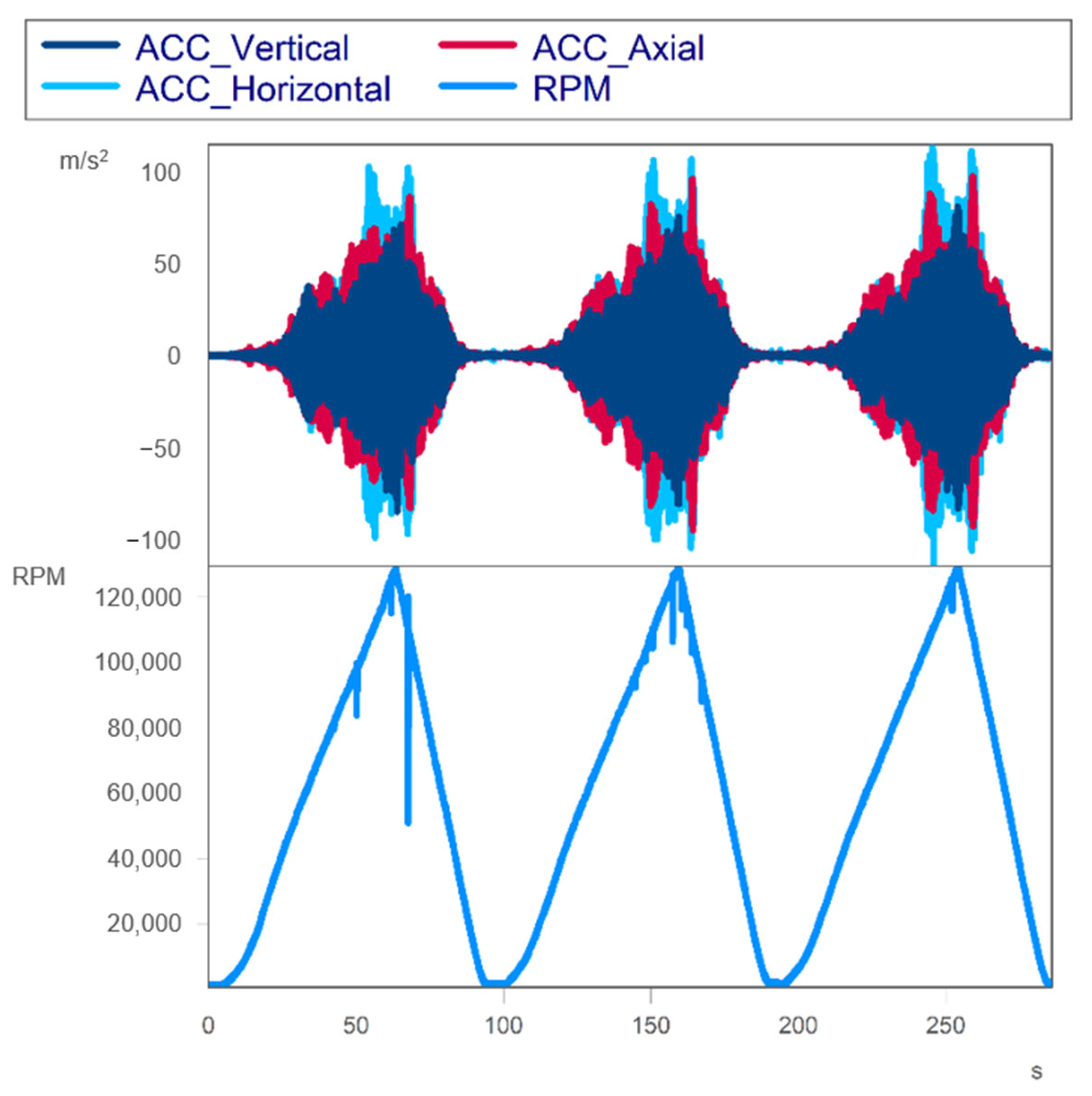
Figure 3 shows the raw data from an example measurement, including readings from all three acceleration sensors (ACC) and the rotational speed sensor (RPM). During the evaluation phase of the research, these datasets were used to generate order spectra (shown on
Figure 4), which formed the basis for the findings.
The data preparation steps included slight smoothing of the rpm signal to eliminate minor signal drops, and then, the dataset was segmented to isolate the sections corresponding to the run-up and run-down phases. The order spectrum, related to the instantaneous rotational speed, was then determined from the time-history of the vibration and tachometer signals. The desired rotational speed range was divided into equal-width classes. Only the vertical and horizontal acceleration signals were used, as the focus of the investigation is on the journal bearing, which is associated solely with radial movements and vibrations.
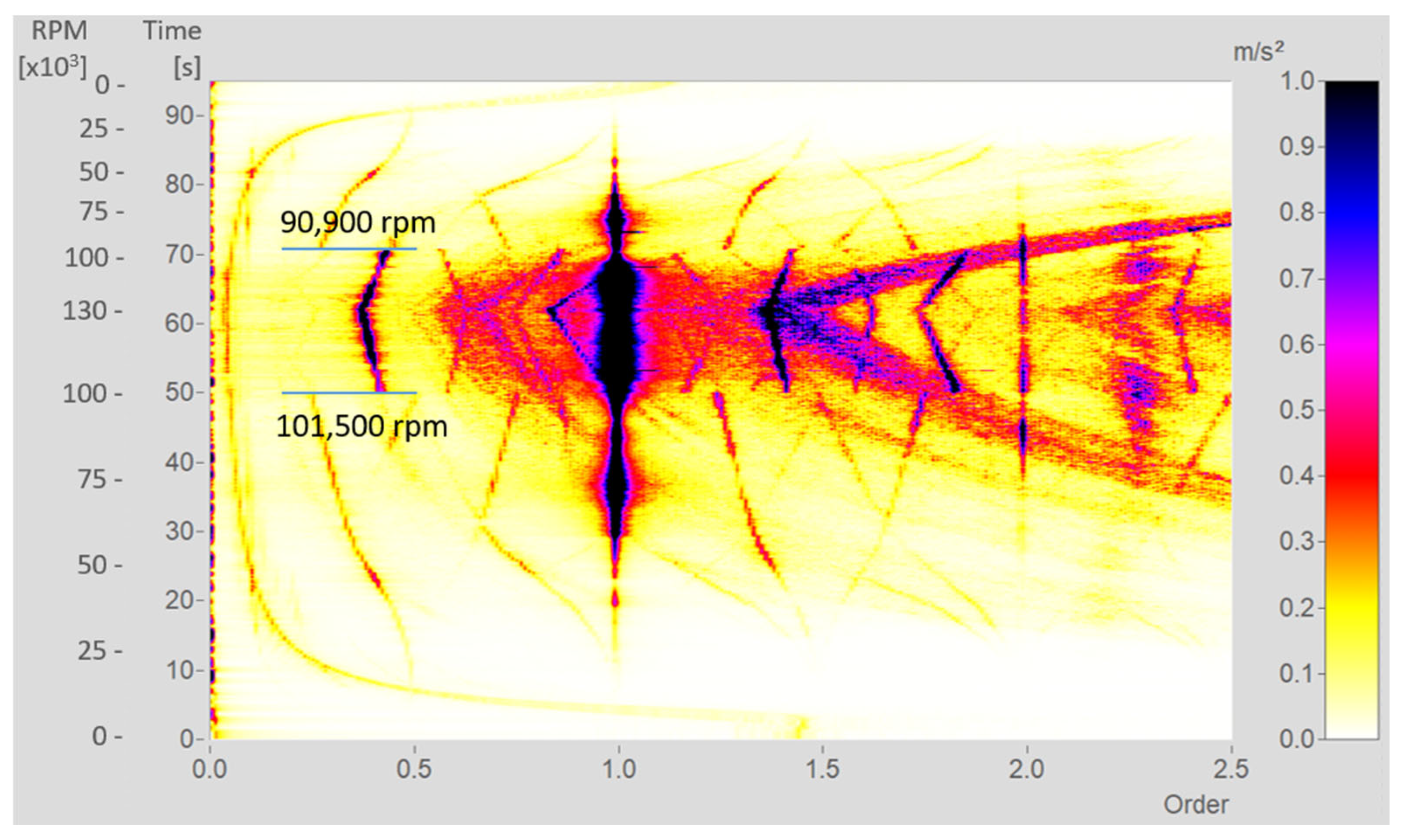
Figure 4 illustrates the order spectrum over time, obtained from a run-up and run-down measurement. The spectrum corresponds to a single measurement using SAE 5W-30 at 80 °C, where the hysteresis phenomenon is distinctly observed. The bifurcation points are indicated by a blue horizontal line, with the rotational speeds measured at 101,500 rpm during the ramp-up and 90,900 rpm during the ramp-down phase. The first subsynchronous component will later be mentioned as Sub 1, which occurs in the lower rpm range (upstream of the bifurcation rpm during ramp-up), and the second subsynchronous component as Sub 2, which appears in the higher rpm range (downstream of the bifurcation rpm during ramp-up).
The color scale is optimized to highlight the subsynchronous components in as much detail as possible. Consequently, the first-order vibrations are not represented with optimal clarity, but it is still evident that when the second subsynchronous component is present, the amplitude of the first-order vibrations increases. This may be attributed to an additional excitation transmitted from the whirling rotor to the lubrication system. It is also noteworthy that both subsynchronous components exhibit multiple modulations at higher order numbers, with a dominant peak around 1.4 orders. This further reinforces the significance of this phenomenon for understanding the system’s dynamics.
The evaluation process involved analyzing 24 distinct datasets, corresponding to the four oils tested at six different temperatures, each producing results similar to those shown in
Figure 4. These datasets were examined from various perspectives, considering two ramp directions and two subsynchronous components, each characterized by their rpm, order position, and vibration magnitude. This approach generated more than 300 data points. Additionally, the measurements were conducted three times for each condition (three ramp-up and three ramp-down tests). The order spectra from these repetitions exhibited variations within 1%, indicating high measurement consistency. Consequently, the middle value of the three repetitions was used for all analyses. The following chapters will present a statistical analysis of these results.
3. Results and Discussion
The characterization of subsynchronous components begins with evaluating bifurcation positions, providing insight into the hysteresis phenomenon.
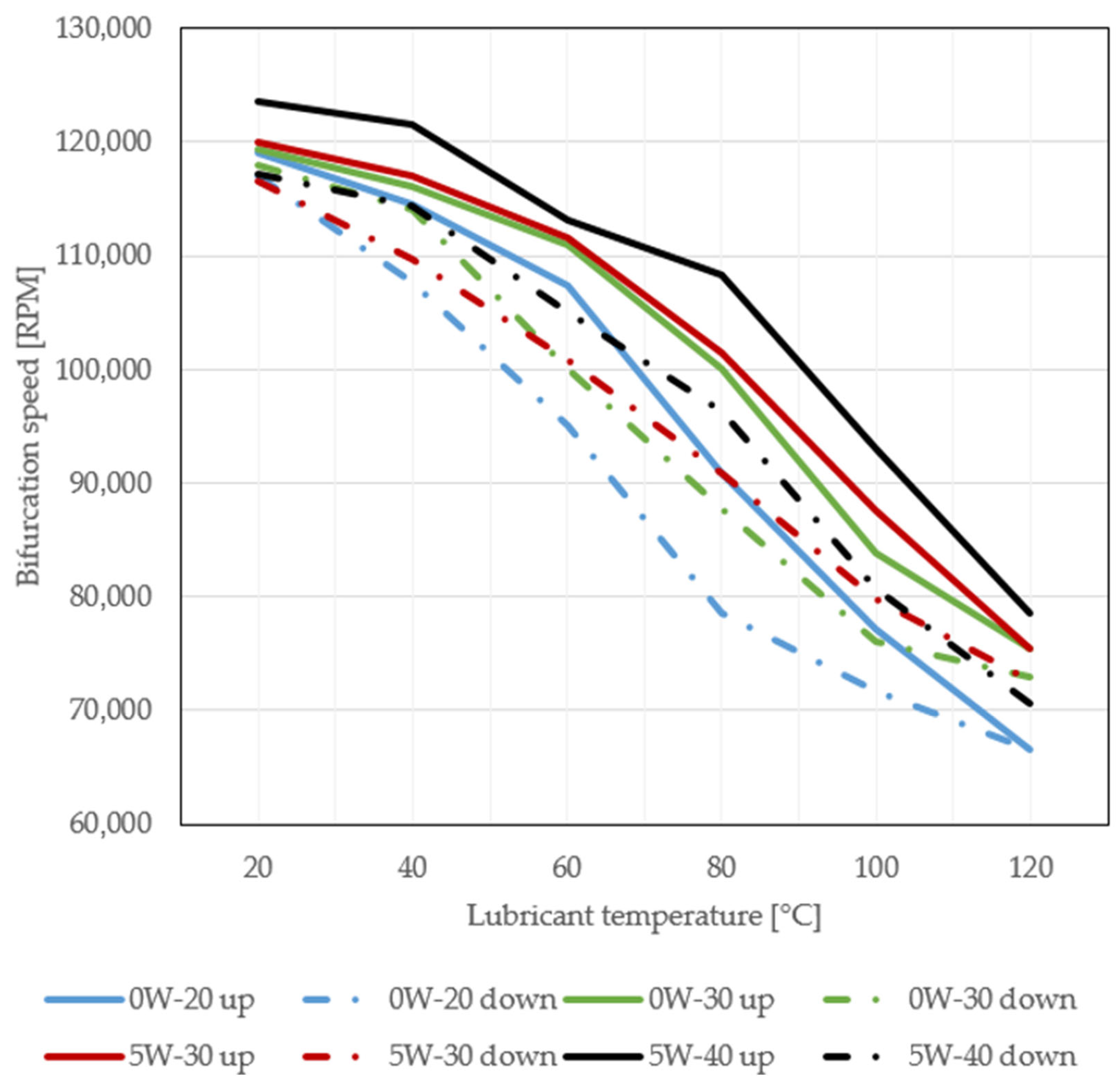
Figure 5 shows the bifurcation points of rotational speed during ramp-up and ramp-down cycles for all oil types and temperature combinations. Solid lines represent ramp-up data, while dashed–dotted lines represent ramp-down data, allowing for a clear comparison.
A consistent trend is observed: lower temperatures and higher oil viscosities result in bifurcations at higher rotational speeds. This suggests a strong correlation between lubricant density and bifurcation points, with denser lubricants shifting bifurcation to higher speeds. The trends also highlight notable differences between run-up and run-down bifurcation speeds, emphasizing the transient nature of the hysteresis phenomenon. These findings underscore the importance of lubricant selection and temperature control in managing subsynchronous vibrations in turbocharger systems.
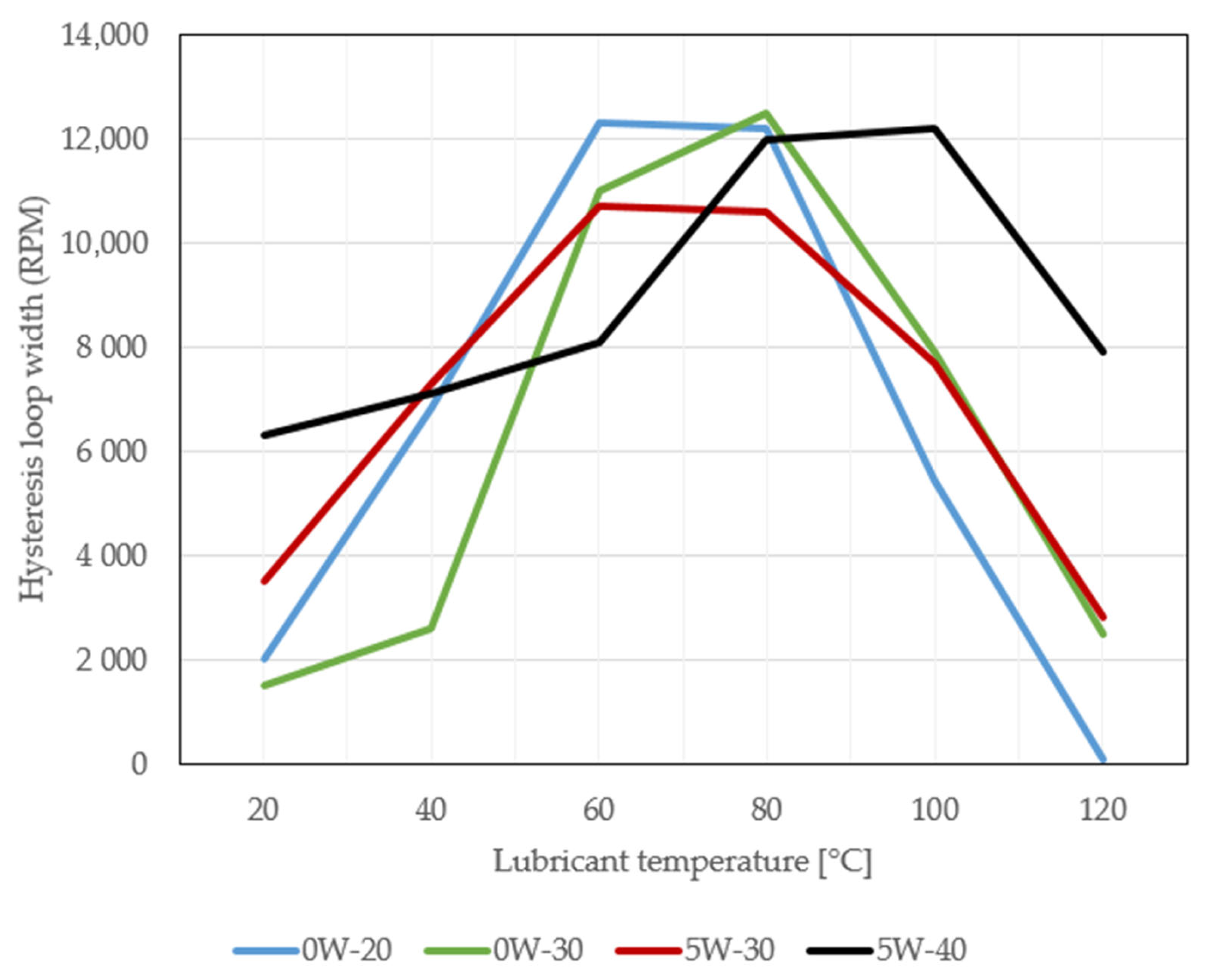
To further investigate the characteristics of the bifurcation speeds, the differences between the ramp-up and ramp-down phases were analyzed. The hysteresis loop width is defined by the difference in rotational speed at which the subsynchronous vibration bifurcation occurs during ramp-up and ramp-down. This width, which is influenced by both lubricant viscosity and oil inlet temperature, provides critical insights into the transient behavior of the turbocharger system. The hysteresis loop width (Δ
N) is calculated as the difference between the bifurcation rotational speeds during ramp-up (
Nup) and ramp-down (
Ndown) cycles:
For each of the four oils tested, the width of the hysteresis loop was quantified at six different inlet temperatures, ranging from 20 °C to 120 °C (see
Figure 6). The results indicate a strong dependency of the hysteresis width on both the oil type and temperature. Notably, the widest loops were observed in measurements conducted with oil temperatures between 60 and 80 °C. The reason for this could be that between 60 and 80 °C, the bifurcation occurs in an rpm range where the rotor, due to its natural frequencies, is more prone to present the hysteresis phenomenon.
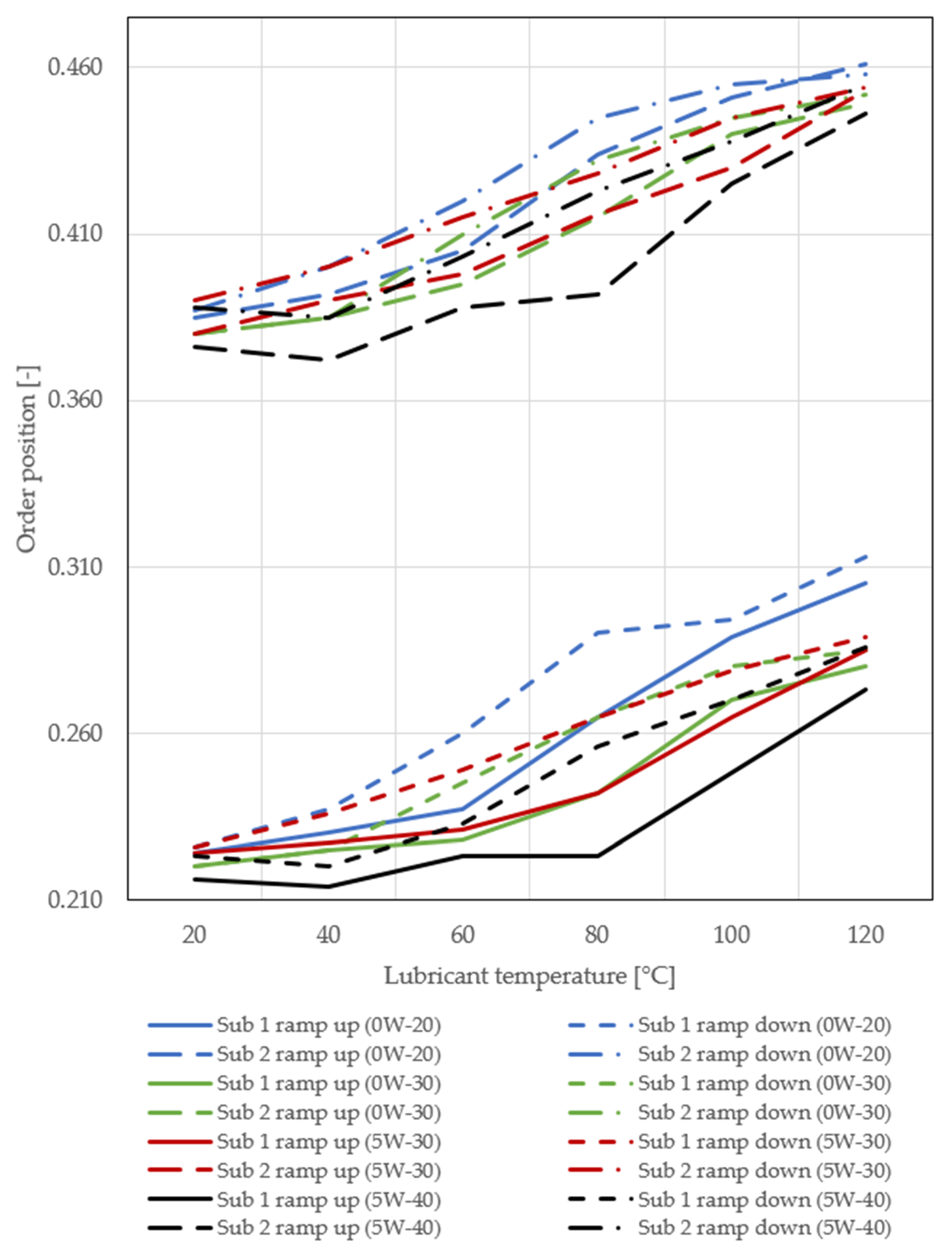
As the next step, the order positions of the two subsynchronous components were analyzed.
Figure 7 summarizes the exact order positions of the first and second subsynchronous components for all investigated cases. The data reveal clear trends, indicating that higher oil viscosity leads to lower order positions. This is true both when the oil type is more viscous and when the temperature is lower. Specifically, Sub 1 order positions ranged from 0.220 to 0.313, while Sub 2 ranged from 0.372 to 0.461. The observed effect could be attributed to the increased damping and stiffness properties associated with more viscous oils and lower temperatures. Higher viscosity oils form a thicker oil film within the bearing, which can alter the dynamic interaction between the rotor and the bearing system, reducing the frequency (and therefore the order) of subsynchronous vibrations. Additionally, the lower temperatures increase oil density and viscosity, further enhancing these effects.
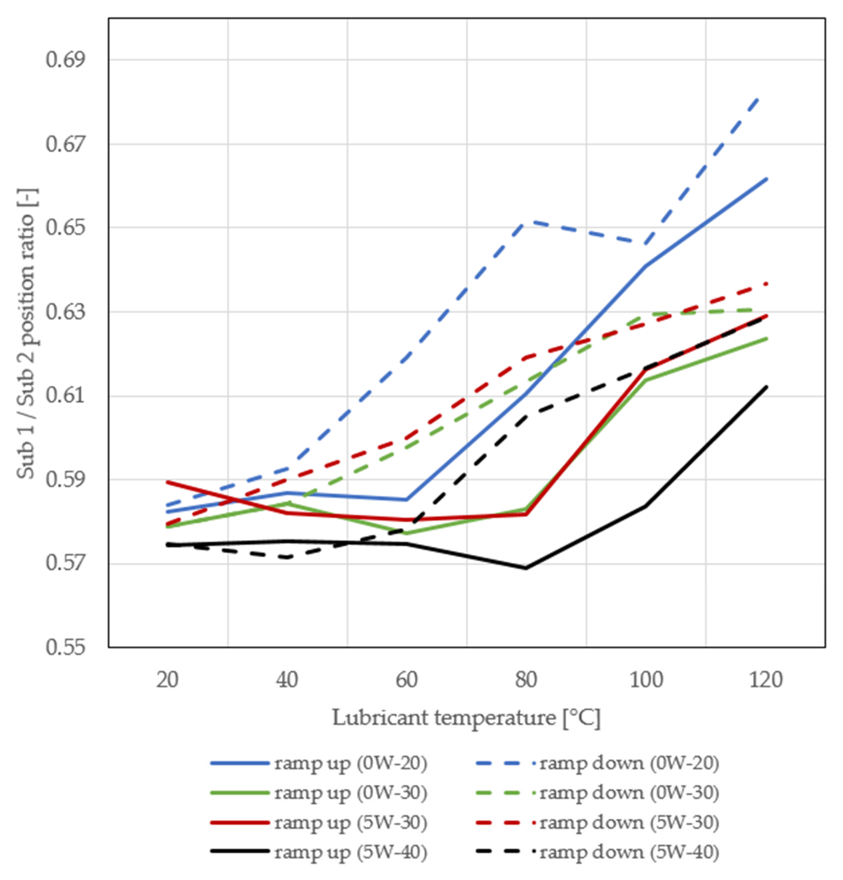
To gain another perspective on the subsynchronous order positions, the ratios of Sub 1 to Sub 2 for the investigated cases were calculated, and they are shown in
Figure 8. This ratio, expressed as a percentage, represents the Sub 1 position divided by the Sub 2 position, indicating how closely the two subsynchronous components approach each other. Interestingly, the data reveal that lower viscosity and higher temperatures result in a higher percentage, suggesting that the subsynchronous components become more closely aligned under these conditions. Additionally, the percentages are consistently higher in the ramp-down cases, which may be explained by the fact that the system experiences less dynamic excitation during ramp-down, leading to smaller position differences between the subsynchronous components.
The reason for this effect could be related to the reduced oil-film thickness at higher temperatures and lower viscosities, which weakens the damping forces and stiffness within the bearing system. As a result, the rotor dynamics become less resistant to excitation, causing the subsynchronous components to converge. Furthermore, during the ramp-down phase, the system’s deceleration allows for reduced energy input, possibly leading to increased coupling between the subsynchronous vibrations, resulting in a higher percentage. This highlights the intricate balance between oil viscosity, temperature, and the system’s vibrational behavior.
4. Conclusions
The results of this study provide insights into the transient behavior of turbocharger rotors with semi-floating ring bearings, particularly the hysteresis phenomenon observed in the subsynchronous frequency range. Key findings indicate that both oil viscosity and inlet temperature significantly influence the bifurcation speeds and subsynchronous order positions. As shown in the bifurcation data, higher oil viscosities and lower temperatures consistently lead to higher bifurcation speeds, indicating increased dynamic stability. Conversely, elevated temperatures result in lower bifurcation speeds, which suggests reduced stability in high-temperature operating conditions. This aligns with the observation that higher temperatures cause thinner oil films, reducing the damping and stiffness of the bearing system.
The analysis of subsynchronous order positions (Sub 1 and Sub 2) further supports these findings, with higher oil viscosities correlating with lower order positions. Interestingly, the ratio of Sub 1 to Sub 2 shows that lower viscosity and higher temperatures cause these components to converge, indicating closer interaction. This effect is more pronounced during ramp-down, possibly due to reduced energy input, which allows the subsynchronous components to approach each other more closely.
Additionally, the hysteresis loop width exhibited a clear temperature dependence, being widest in the 60–80 °C range, where the rotor appears more sensitive to hysteresis due to its natural frequencies. These results suggest that the rotor’s mode shapes, in combination with lubrication properties, play a significant role in the system’s overall dynamic behavior.
In conclusion, understanding the interactions between oil properties, temperature, and subsynchronous vibrations is crucial for optimizing turbocharger performance and stability. These findings provide a strong foundation for further research into the complex rotor dynamics of turbochargers and the role of the hysteresis in subsynchronous vibrations.


