Article

A Preliminary Study on Wear Resistance and High-Temperature Steam Oxidation of AlCrFeMoZr High-Entropy Alloy Coatings for Accident-Tolerant Fuel

1
School of Mechanical Engineering, University of South China, Hengyang 421001, China
2
Hunan Provincial Key Laboratory of Emergency Safety Technology and Equipment for Nuclear Facilities, University of South China, Hengyang 421001, China
3
School of Aeronautical Engineering, Hunan Automotive Engineering Vocational University, Zhuzhou 412001, China
*
Authors to whom correspondence should be addressed.
Lubricants 2025, 13(12), 511; https://doi.org/10.3390/lubricants13120511 (registering DOI)
Submission received: 18 October 2025 / Revised: 19 November 2025 / Accepted: 19 November 2025 / Published: 23 November 2025
(This article belongs to the Special Issue Mechanical Tribology and Surface Technology, 2nd Edition)

Abstract

High-entropy alloy (HEA) coatings have attracted significant attention in the nuclear power field due to their exceptional properties, showing great potential for accident-tolerant fuel (ATF) applications. In this study, novel AlCrFeMoZr HEA coatings with a near-equal molar ratio were successfully fabricated via magnetron sputtering at different bias voltages (−50 V, −100 V, and −150 V). The influence of bias voltage on the microstructure and mechanical properties of the coatings was systematically investigated. The results reveal that all HEA coatings exhibit a body-centered cubic structure with a (110) preferential orientation. As the bias voltage increased, the Al content in the HEA coating decreased, and the microstructure coarsened. The microhardness and friction and wear test results demonstrate that an HEA coating deposited at −100 V exhibited optimal mechanical properties owing to its good balance between hardness and toughness, leading to an improved tribological performance. Furthermore, a high-temperature water vapor oxidation experiment was conducted at 1200 °C in order to preliminarily study the differences in the anti-oxidation behavior of the new composition, an AlCrFeMoZr HEA coating, when deposited at various biases.

1. Introduction

The 2011 Fukushima nuclear accident demonstrates that the zirconium alloys under loss-of-coolant accident conditions undergo a violent zirconium–water reaction with steam, generating large amounts of hydrogen gas and heat, which can potentially trigger hydrogen explosions and severely compromise the safety barriers of nuclear reactors [1,2]. This accident attracted worldwide research on the failure mechanism of the fuel cladding tubes made by zirconium alloys [3,4] and also accelerated global research on Accident-Tolerant Fuel (ATF) aimed at enhancing the safety margins of nuclear power plants.
Current research on ATF-cladding technology primarily follows two technical routes. The first involves developing entirely new cladding-material systems to replace zirconium alloys, such as silicon carbide composites (SiC) and iron-based alloys (FeCrAl). However, these new material systems face numerous challenges. For instance, FeCrAl alloys suffer from severe Al component interdiffusion between the FeCrAl coating and the zirconium matrix at high temperatures, along with inherent difficulties in processing. The SiC composites also face challenges like high manufacturing costs for tubing and complex joining technologies [5,6]. The second route focuses on developing coatings with excellent oxidation resistance. Coating technology offers outstanding advantages, such as short development cycles, high feasibility, and good economic efficiency, making it a key focus area in global ATF research [7,8,9,10,11,12]. In addition, coating technology can significantly enhance the accident tolerance of cladding materials without compromising their original properties.
Among numerous candidate coating materials (such as ceramic MAX phases, SiC, metal alloys, etc.), the Cr coatings are considered as one of the most promising ATF coating candidates. However, the commercial application of chromium-coated cladding still faces two core challenges: First, the columnar grain structure formed by traditional physical vapor deposition processes tends to create interconnected grain boundaries, providing fast diffusion pathways for oxygen [11]. Second, the brittle ZrCr2 intermetallic compounds form at the Cr-Zr interface at high temperatures, posing a risk of coating spallation [12].
In recent years, inspired by the pioneering work of Yeh, Cantor, and others [13], high-entropy alloy (HEA) coatings have garnered widespread attention as a new type of ATF coating material. Composed of multiple principal elements, HEAs exhibit unique characteristics like the high-entropy effect, severe lattice distortion, sluggish diffusion effect, and “cocktail” effect, demonstrating great potential for overcoming the limitations of traditional coatings. Particularly, their significant sluggish diffusion effect is expected to effectively suppress component interdiffusion between the coating and the zirconium substrate at high temperatures, which might offer a new approach to solving the interdiffusion problem encountered in FeCrAl/Zr systems. In addition, their high strength and good thermal stability also contribute to enhancing the overall performance of the coating [14]. Furthermore, previous studies have shown that HEA coatings also possess advantages in wear resistance. It has been demonstrated that eutectic high-entropy alloys like AlCoCrFeNi2.1 can form protective nanocrystalline–amorphous composite oxide layers on their surfaces during friction across a wide temperature range, significantly improving the wear resistance of the coating, and this is crucial for resisting fretting wear induced by flow-induced vibration within reactors and for extending cladding lifespan [14]. Based on these studies, research on HEA coatings, particularly those based on the AlCrFe system, has also been rapidly expanded. Current research mainly focuses on two aspects: Firstly, optimizing coating performance through composition design, such as developing multi-component systems like AlCrFeMoTi and AlCrFeTiNb, to control phase composition, enhance corrosion resistance, and improve irradiation resistance [15,16]. Secondly, precisely controlling the coating’s microstructure, density, and adhesion to the substrate by optimizing process parameters, such as deposition power, substrate temperature, working gas pressure, and bias voltage [17].
Based on our previous works on coating fabrication [18,19], this paper studies a new composition AlCrFeMoZr HEA coating prepared by magnetron sputtering under different levels of bias. The effects of bias on the microstructure, mechanical properties, friction and wear behavior of the coatings, and resistance to high-temperature steam oxidation were systematically investigated in order to provide a reference for developing safer advanced nuclear fuel technologies.

2. Materials and Methods

2.1. Coating Preparation

The AlCrFeMoZr high-entropy alloy coating was prepared using a three-target, ultra-high-vacuum, magnetron sputtering system (Chengdu Qixing Vacuum Coating Technology Co., Ltd., Chengdu, China). The substrate was a 316 stainless steel bar with a diameter of 10 mm and a length of 2 mm. Before deposition, the substrate was sequentially ground and polished with SiC sandpaper of different grit sizes, then ultrasonically cleaned in acetone and absolute ethanol for 15 min each, and dried for use after cleaning.
The nominal chemical composition of the target used is Fe 16%, Cr 21%, Al 21%, Mo 21%, and Zr 21%, with dimensions of 78 mm × 7 mm. It should be particularly noted that due to the titanium alloy material of the internal support frame in the magnetron sputtering system, a trace amount of Ti element is inevitably sputtered and incorporated into the final coating during the deposition process. The focus of this study lies in the AlCrFeMoZr matrix system; thus, the impact of this introduced Ti impurity element can be ignored.
The pretreated sample is fixed on a custom sample holder capable of simultaneous rotation and revolution, ensuring uniform coating deposition across all surfaces. Prior to deposition, the substrate undergoes a 10 min Ar+ reverse sputtering cleaning at −700 V and 2 Pa Ar pressure to remove surface contaminants and oxides. Coating deposition then proceeds under optimized parameters: sputtering power 1200 W; substrate temperature maintained at room temperature; bias voltages at −50 V, −100 V, and −150 V; deposition duration 8 h; target-to-substrate distance 100 mm; and working pressure (Ar) 0.7 Pa. Before deposition, the sample bias is deactivated, RF power is set to 1200 W, and chamber pressure is precisely adjusted to 0.7 Pa for a 10 min target pre-sputtering to clean the samples’ surfaces and stabilize the plasma. After deposition, the sample furnace cools within the coating chamber under a continuous Ar-protective atmosphere to prevent coating oxidation.

2.2. Microstructure Characterization

The crystal structure of the coating was characterized using an X-ray diffractometer (XRD, MiniFlex 600 type, Rigaku, Osaka, Japan). The test employed Cu target Kα radiation as the radiation source, with the X-ray tube operating voltage and current set to 40 kV and 15 mA, respectively. Continuous scanning mode was employed with a scanning range of 2θ = 20–90°, scanning speed of 5°/min, and step size of 0.02°. By analyzing the XRD diffraction pattern of the coating, its phase composition and crystal structure could be determined, thereby correlating the coating’s structure with its properties.
High-resolution observations of the coating’s surface morphology, wear scar morphology after abrasion, and polished cross-sectional morphology were observed using a field emission scanning electron microscope (SEM, model: MIRA4, TESCAN, Bohunice, Czech Republic) equipped with a high-performance X-ray energy-dispersive spectrometer (EDS, model: XPLORE 30, Oxford, UK), enabling simultaneous qualitative elemental mapping, line scanning analysis of micro-regions of interest during morphological observation, and quantitative point composition analysis. This can provide critical data for investigating the uniformity of elemental distribution in the coating, oxide film composition, and diffusion behavior.

2.3. Microhardness and Tribological Properties Tests

The micro-hardness (HV) test was measured using a Vickers hardness tester (MHVD50AP, Shanghai Jujing Precision Instrument Co., Ltd., Shanghai, China). Microhardness testing was conducted in accordance with ASTM E384 [20] standard. Seven indents were tested for each sample with a load of 1.96 N for 10 s at room temperature.
The tribological properties of the coating were tested using a reciprocating friction and wear tester (model: ZD-WPM-20, Shandong Zongde Electromechanical Equipment Co., Ltd., Dezhou, Shangdong, China) at room temperature. The experiment was performed according to ASTM G99 [21] standard and employed smooth-surface silicon nitride (Si3N4) ceramic balls as the counter material to simulate wear contact. Test conditions were set as follows: vertical load 2 N and reciprocating frequency 2 Hz. Through this experiment, the variation curve of the coating’s coefficient of friction over time was quantitatively obtained, and its wear resistance was subsequently evaluated by analyzing the morphology of the wear scar.

2.4. Water Vapor Corrosion Test

To investigate the oxidation resistance of coatings under LOCA accident conditions, we designed a high-temperature steam oxidation experiment under an extreme/harsh environment. To investigate the oxidation resistance of coatings under LOCA accident conditions, this study designed a high-temperature steam oxidation experiment. The test was conducted in a vertical tube furnace (Model: NBD-LT1600-60IT Nobadi Materials Technology Co, Ltd., Zhengzhou, Henan, China). To prevent thermal shock and ensure uniform heating during temperature ramping, a programmed heating curve was implemented: a gentle 5 °C/min rate from room temperature to 500 °C; an increased 10 °C/min rate between 500 °C and 800 °C to shorten transition time; and a return to 5 °C/min beyond 800 °C until reaching 1200 °C. Once the furnace stabilized at 1200 °C, pre-prepared samples were swiftly transferred to the isothermal zone, initiating the holding timer immediately. Throughout the oxidation test, steam flow was strictly maintained at 1.3 mg/(cm2·s) via a precision steam generation/delivery system, simulating a stable and controlled steam oxidation environment.

3. Results and Discussion

3.1. Coating Morphology and Microstructure

The XRD patterns of the AlCrFeMoZr coating fabricated with different bias voltages are shown in Figure 1. It can be seen that all the coatings present a primary broad peak at a diffraction angle 2θ = 41.5° and a secondary weak and wide diffraction peak at about 2θ = 72°, which is similar to the previous results reported in the studies [22,23]. According to studies [24,25,26], the broadening of the diffraction peak of the AlCrFeMoZr coating indicates the formation of an amorphous or nanocrystalline phase in the coating, which can be ascribed to the rapid cooling rate during the magnetron sputtering process [27].
As is reported in the literature [22,23], the appearance of a primary broad peak at diffraction angle 2θ = 41.5° indicates that all coatings exhibit a body-centered cubic structure with a (110) preferential orientation. By using the 2θ value corresponding to the characteristic peaks, we can calculate the lattice constants for the coatings BCC phase (shown in Table 1), and the lattice constants decrease from 3.177 Å to 3.138 Å as the bias voltage increases from −50 W to −150 W.
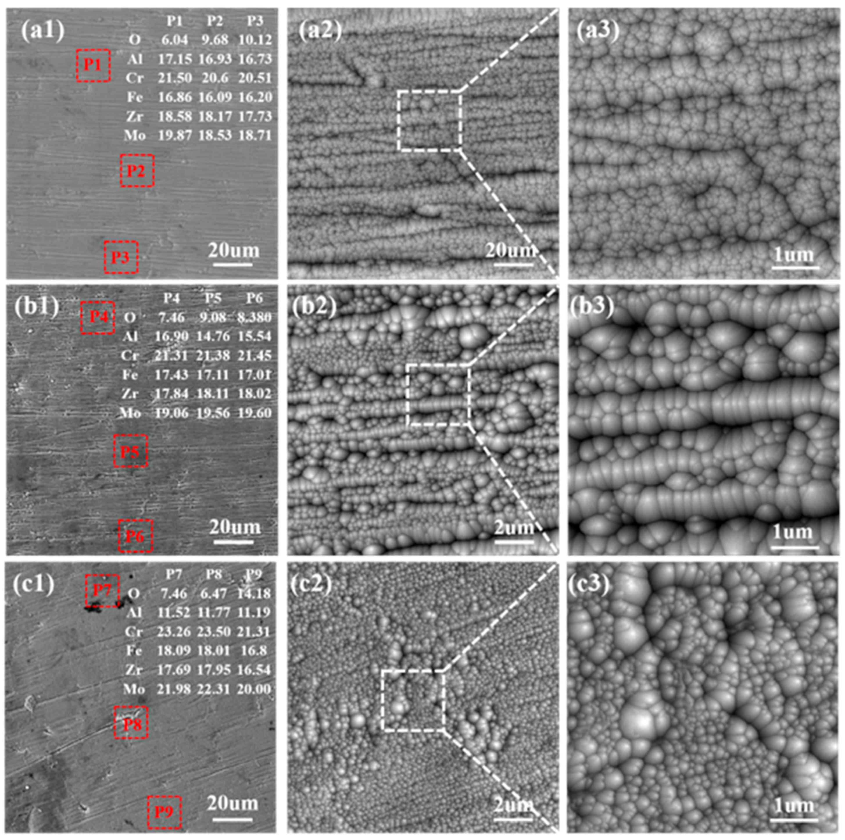
Figure 2 shows the SEM images of the top surface of AlCrFeMoZr coatings deposited at different biases. Gullies and particles can be observed in all the coatings’ surfaces shown in low-magnification morphologies in Figure 2(a1,b1,c1). Corresponding EDS analysis results of the coatings are inserted in the corresponding SEM images, and the atomic percentage of Al, Cr, Fe, Mo, and Zr was detected. The EDS is measured with three independent area-scanning analyses in each coating, and the results illustrate that all those elements have almost equal molar ratio compositions [22,28,29,30], while the actual composition of the co-sputtered films is quite close to the nominal composition. In addition, it can be found that the Al content in the coating decreases with the bias increase. As is shown in Table 1, the multicomponent BCC lattice constant is in the range 0.3138–0.3177 nm and decreases with the increasing of bias voltage due to the decrease in the larger Al atom compositions. This is similar to the result discussed in the literature [31].
Moreover, the surface roughness of the coatings becomes smoother and cleaner as the biases increase (shown in Figure 2(a1,b1,c1)). Figure 2(a2,b2,c2) show the coatings’ morphologies in high magnification, and more microstructural details are present. No cracks and voids can be observed in the coating. It can be clearly seen that the coatings are composed of nanoparticles with different dimensions, as the biases varied. Those amounts of nanoparticles with sizes of tens to hundreds nanometers gather together in the coatings surface, which is also observed in Liu’s research [32], and the size of those nanoparticles increases as the bias voltage rises.
Figure 3 shows the 3D roughness profile of the coatings. Results show that all coatings exhibit morphologies with flattened peaks and valleys. The coating at −50 V exhibits the maximum peak–valley height difference of about 2.7 mm, and the coating at −100 V exhibits the minimum peak–valley height difference of 1.9 mm. Figure 3d shows the relation between surface roughness (Ra) and bias voltages corresponding to those discussed above. It can be clearly seen that the coatings reach a near Ra value, and the coating at 50 V reaches the minimum Ra (0.09 mm). These results are consistent with the previous SEM observation shown in Figure 2.
Figure 4 shows the cross-section microstructures of the AlCrFeMoZr coatings deposited under different Biases. All coatings had a uniform thickness of approximately 8–9 mm and exhibited similar dense and compact structures. No cracks and voids can be observed between the substrate and the coating, which indicates good adhesion and good deposition quality, and no columnar structures can be observed in the coatings [28].

3.2. Coating Microhardness and Tribological Properties

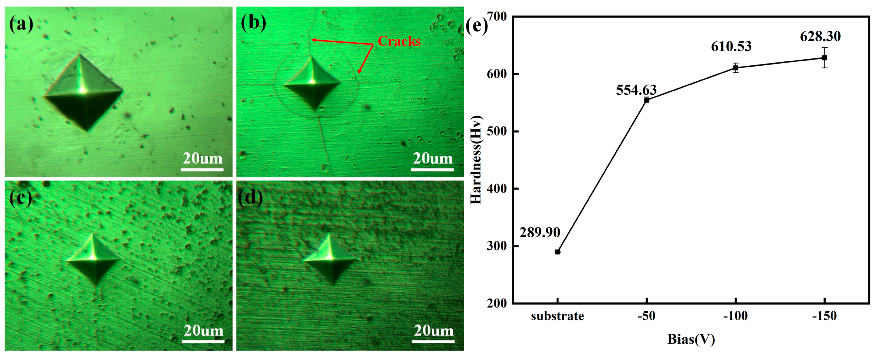
The micro-hardness experiment results of the bare substrate and AlCrFeMoZr coatings are presented in Figure 5. Figure 5a–d display the indentation images of the substrate and coatings at different biases, and Figure 5e shows the curve of the micro-hardness values versus bias. It can be seen that the indentation of the bare substrate exhibits the largest size, which indicates the lowest micro-hardness value. It can also be seen in Figure 5e that the micro-hardness value increases as the bias increases, from a minimum 554.63 HV for coating at −50 V to a maximum 628.3 HV for coating at 150 V. In addition, cracks distributed around the indentation can be observed in the coating at 50 V and coatings, indicating insufficient toughness under low bias voltages [28]. As the bias voltage increased from −100 V to −150 V, no cracks were found. This is due to high-energy ion bombardment at higher bias voltages improving the coatings’ densification, which can enhance the coatings’ toughness.
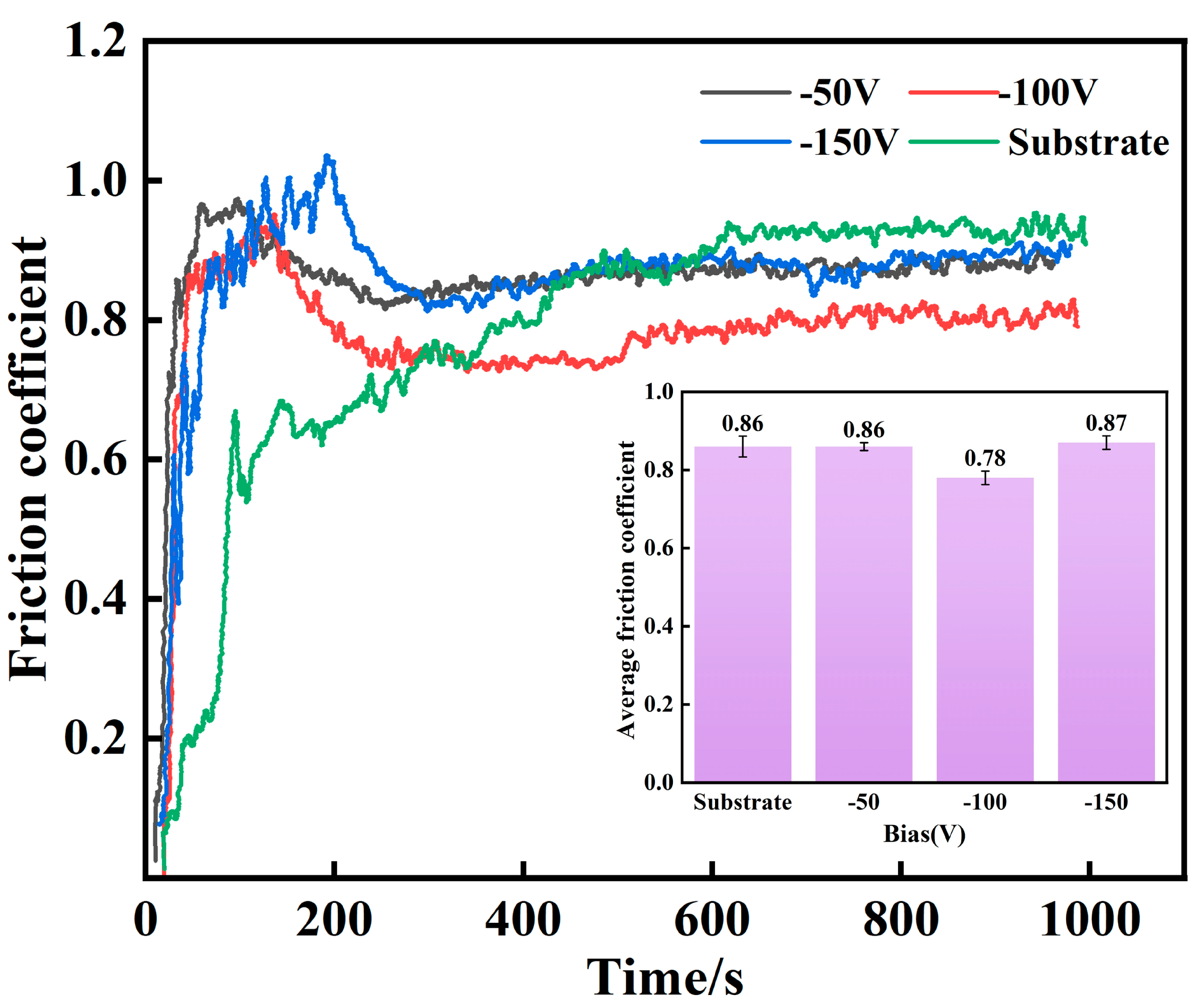
The friction and wear tests were carried out at RT in order to explore the tribological properties of the AlCrFeMoZr coatings. Figure 6 shows the coefficient of friction (COF) curves as a function of time for the bare substrate and coated samples at different biases. With an increase in the sliding time, the COF of all the tested samples gradually increased and then fluctuated at a relatively stable value. It can be seen that the COF of the bare substrate continuously increases and reaches a stable running-in stage till about 500 s. However, the COF of the AlCrFeMoZr coatings reaches a maximum, decreases, and then reaches a stable running-in stage at about 200 s. The time of the COF running-in stage of the bare substrate is longer than that of the coatings, which demonstrates a worse occlusion between the counterpart and the substrate surface induced by an increase in the substrate surface roughness [33]. In addition, it can also be noticed that the COF for coatings at 50 V and 150 V achieves a close stable value. However, the COF for coating at −100 V achieves a lower stable value than that of samples at −50 V and −150 V. The average COFs of the coatings at −50 V, −100 V, and −150 V are 0.86, 0.78, and 0.87, respectively, as displayed in the inserted histogram in Figure 6.
To compare the wear resistances of the coatings at different biases, the low magnification morphology and the widths of the wear tracks were obtained (shown in Figure 7). It can be obviously seen in Figure 7a,c that there are irregularly shaped notches at the track’s edge, and some coating fragments can be observed on the surface near the track’s edge, which implies the coatings at −50 V and −150 V have peeled off during the wear and friction test. In contrast, tracks of coating at −100 V exhibit an unbroken edge, shown in Figure 7b. The coating fragments further prompt the accumulation of wear debris into larger particles, which resulted in an increase in the COF and shear stress, in turn accelerating the wear and the breakdown of the coating [34,35,36]. Therefore, the −100 V samples exhibited no accumulation of wear particles on the worn surface, corresponding to the lowest wear rate. The track widths were measured, and the average values are shown in Figure 7d. The figure illustrates that the wear track width of the coating at 100 V exhibits a minimum value (0.71 mm), which also proves that the 100 V coating shows the lowest wear rate.
Hence, as is discussed above, the −150 V coating possesses higher hardness; its inferior tribological performance, governed by poor adhesion, underscores a critical principle for fretting-wear applications: the adhesion strength of the coating to the substrate is as crucial as its intrinsic hardness in determining long-term performance. However, the −100 V deposition condition appears to strike an optimal balance between achieving sufficient hardness and maintaining exceptional adhesion, thereby yielding the best overall wear resistance.
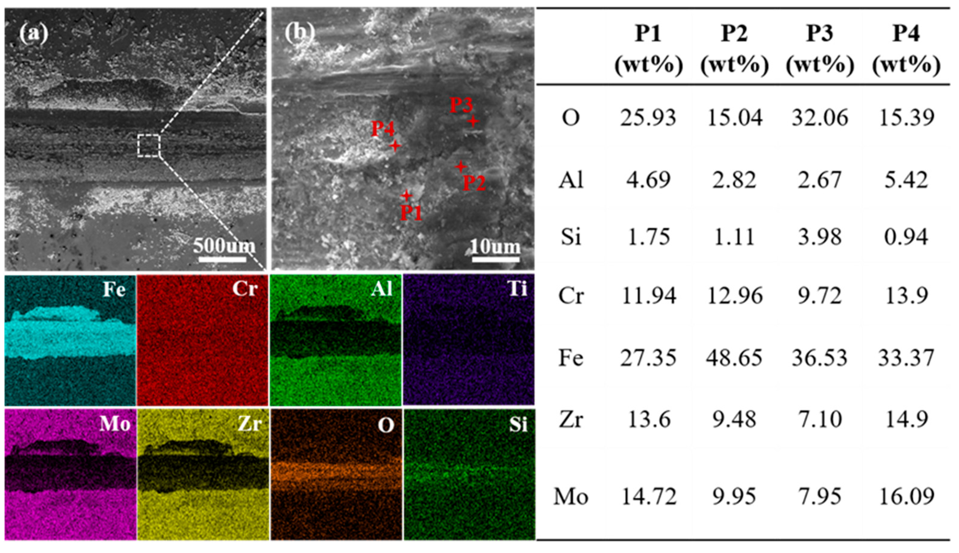
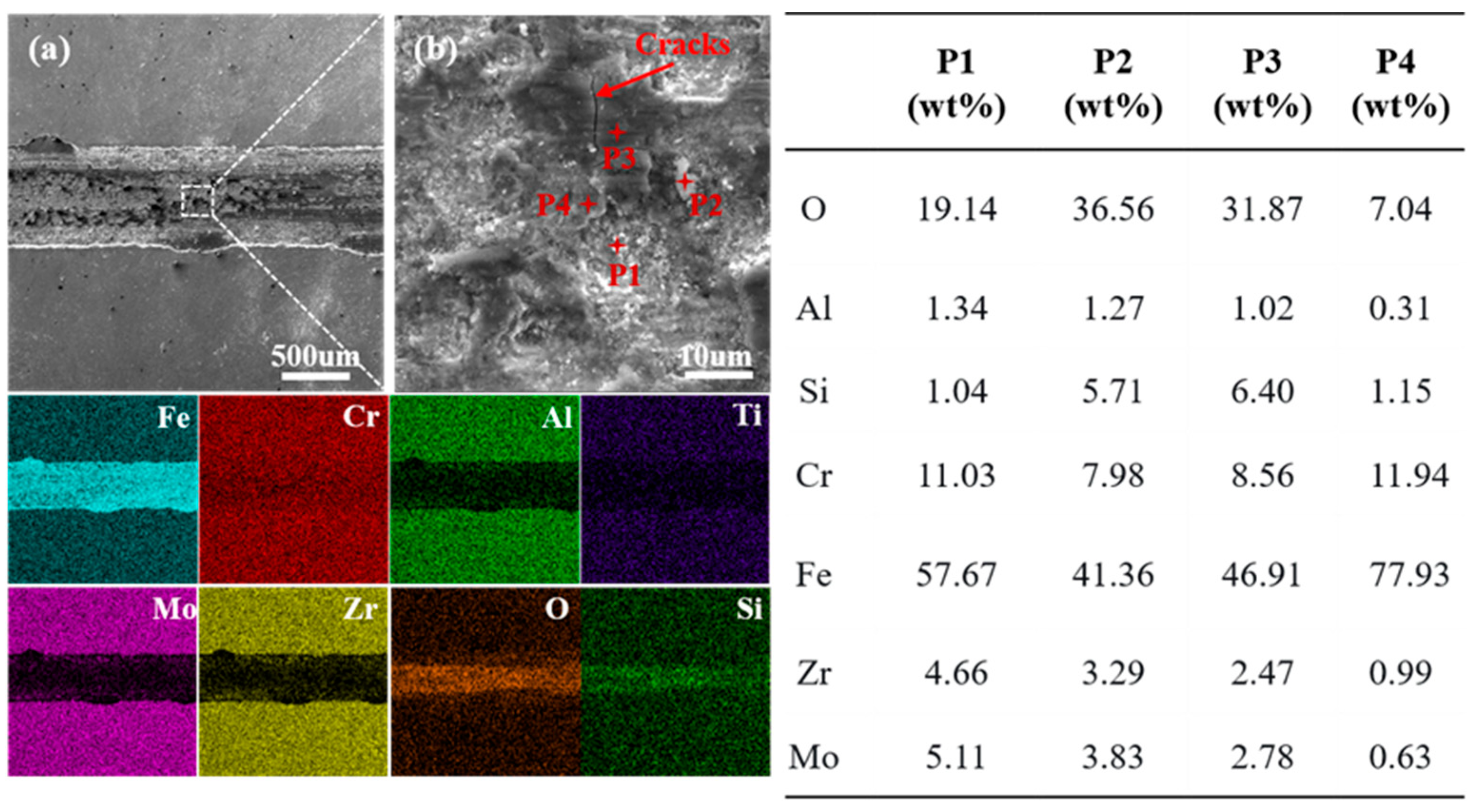
To further elucidate the tribological behavior of the AlCrFeMoZr HEA coating, SEM and EDS observations of the worn tracks of the coatings at −50 V, −100 V, and 150 V are shown in Figure 8, Figure 9, and Figure 10, respectively. It can be found that the worn tracks of all the coatings exhibit similar microstructure characteristics. Granular debris and flaky debris of varying sizes are distributed across the entire worn tracks, which is a typical abrasive wear morphology [37,38,39,40]. EDS point analysis results indicate the composition of this debris are oxides. In addition, the EDS mapping results show the presence of Si elements within the tracks, indicating that adhesive wear occurred between the grinding ball and the coating during the friction and wear test, resulting in material transfer between them [41,42,43].

3.3. Coating Water Vapor Corrosion

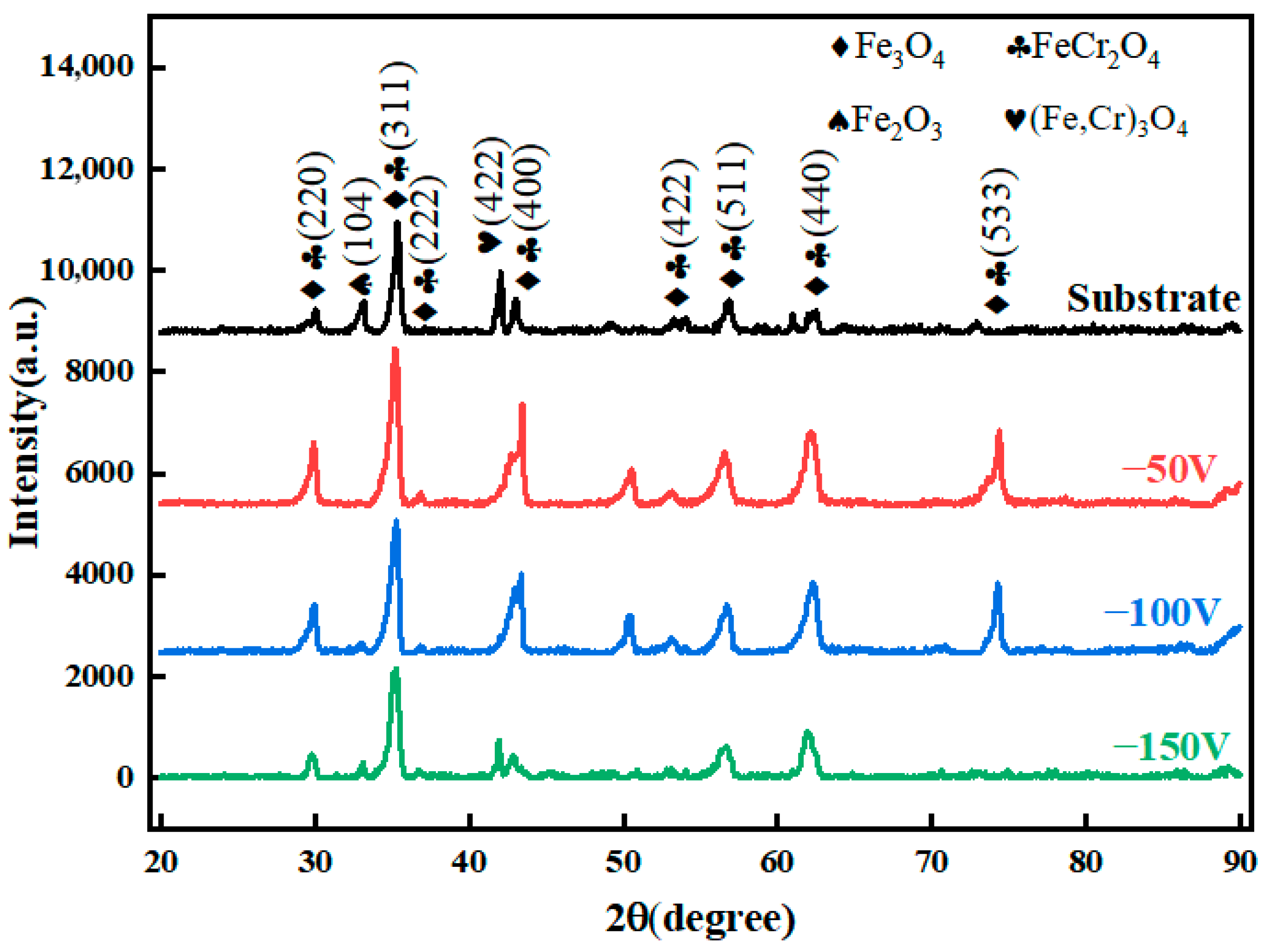
Figure 11 shows XRD patterns of the uncoated steel substrates and the AlCrFeMoTi HEA coatings after 30 min water vapor oxidation at 1200 °C. The surface oxides of the steel substrates are identified to be magnetite Fe3O4 (ICDD PDF# 75 0033) and spinel (Fe,Cr)3O4 (ICDD PDF# 99 0030), which has been reported [44,45]. The characteristic primary broad diffraction peak and the second weak broad diffraction peak of the HEA AlCrFeMoTi coatings pattern disappeared after corrosion, and only peaks of oxide products Fe3O4 (ICDD PDF# 75 0033) and (Fe,Cr)3O4 (ICDD PDF# 99 0030) can be identified, indicating the instability of the coatings’ structure in such a corrosion condition [22].
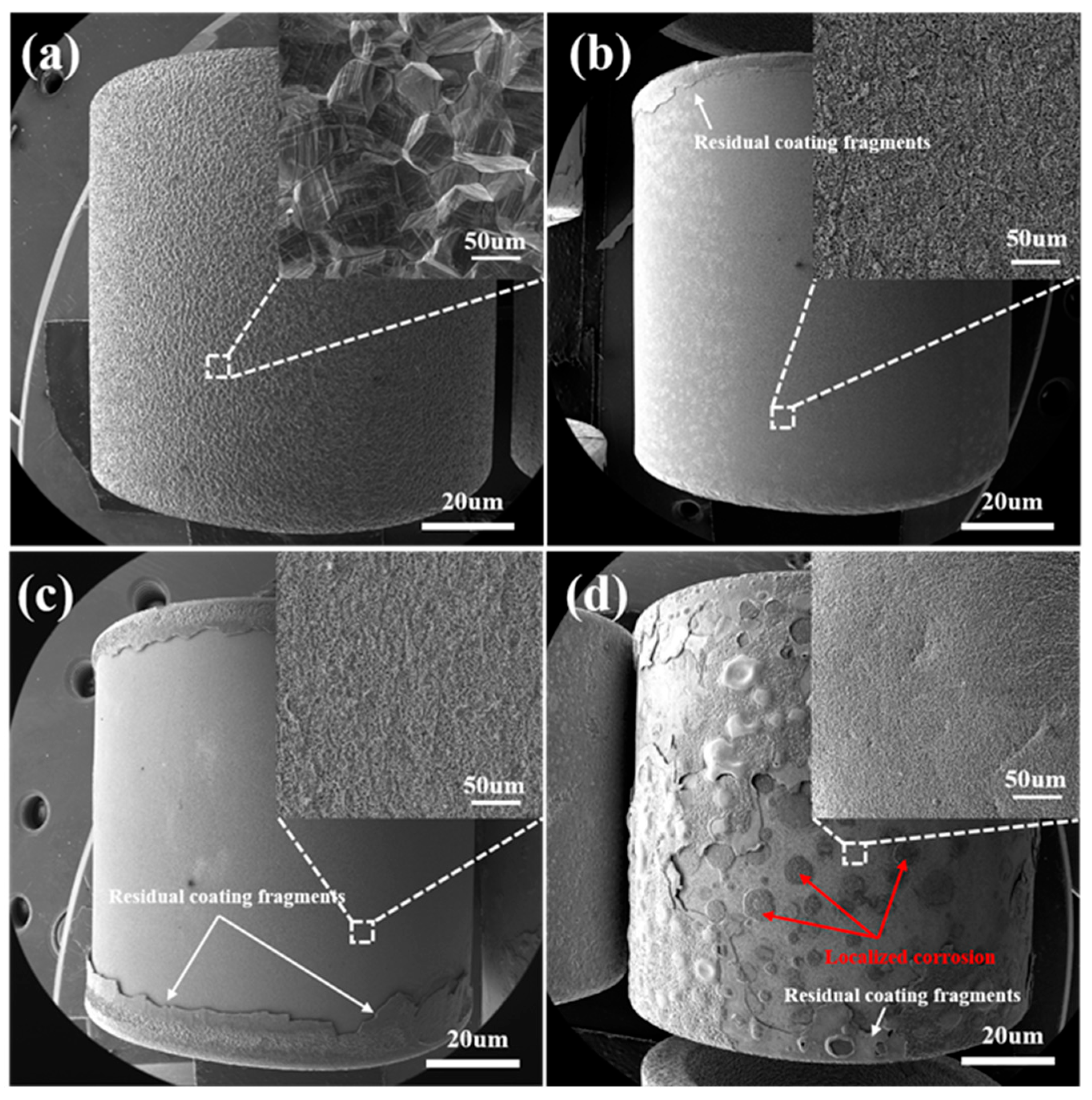
The surface morphologies of the substrate and coatings after corrosion are shown in Figure 12. As shown in Figure 12a, the bare substrate surface exhibits a bumpy morphology after corrosion, and a coarse and loose oxide layer was formed on the surface after corrosion, which is consistent with previous research [45]. It can be found that all the coatings peeled off during corrosion, and residual coating fragments are labeled in the figures. Besides, the coatings at −50 V and −100 V show smoother morphologies, and dense and fine oxide layers were formed on the surface, which is advantageous for oxidation resistance [22]. However, amounts of lumps are distributed on the coating at −150 V, which indicates a severe localized corrosion occurred during water vapor corrosion.

4. Conclusions

In this work, novel AlCrFeMoZr high-entropy alloy coatings were successfully fabricated on 316 stainless steel substrates via magnetron sputtering at various bias voltages (−50 V, −100 V, and −150 V). The systematic investigation into the effects of bias voltage on the microstructure, mechanical properties, and high-temperature water vapor oxidation resistance leads to the following conclusions:
Microstructure Evolution: All deposited coatings exhibited a body-centered cubic (BCC) structure showing a (110) preferential orientation. EDS results show that the Al content in the HEA coating decreases with the bias increase, which results in the multicomponent BCC lattice constant decrease. The coatings are composed of nanoparticles with different geometric morphologies that gather together on the coating’s surface, and those nanoparticles become coarser as the bias voltage increases.
Mechanical and Tribological Properties: The microhardness of the coatings showed a positive correlation with bias voltage, increasing from approximately 554.6 HV at −50 V to 628.3 HV at −150 V, attributed to enhanced ion bombardment and densification. However, the coating deposited at −100 V demonstrated the most favorable tribological performance, characterized by the lowest and most stable coefficient of friction (0.78) and the narrowest wear track. This is attributed to its optimal combination of hardness and toughness, which minimizes coating delamination and abrasive wear.
High-Temperature Steam Oxidation Resistance: After exposure to 1200 °C steam for 30 min, all coatings partially peeled off after oxidation. The characteristic BCC structure of the HEA coatings disappeared after corrosion; typical oxide products identified as Fe3O4 and (Fe,Cr)3O4 were formed. The coating deposited at −50 V and −100 V formed a relatively dense and refined oxide layer after oxidation resistance. In contrast, the −150 V coating experienced severe localized oxidation, indicating a degradation in protective performance at excessively high bias voltage.
In summary, the bias voltage plays a critical role in determining the comprehensive performance of AlCrFeMoZr HEA coatings. While higher bias promotes hardness, an optimal balance between mechanical integrity, tribological behavior, and oxidation resistance is achieved at a bias voltage of −100 V. This makes the −100 V coating the most promising candidate for further development as an accident-tolerant fuel (ATF) cladding coating, effectively leveraging the advantages of high-entropy alloys for enhanced nuclear safety.

Author Contributions

Conceptualization, J.H.; methodology, Y.W. and Y.L.; software, J.H., P.Y., Y.W. and Y.L.; validation, Y.W.; formal analysis, Y.W.; investigation, Y.L.; resources, Y.W.; data curation, Y.W.; writing—original draft, Y.W.; writing—review and editing, J.H. and P.Y.; visualization, Y.L.; supervision, P.Y. and J.H.; project administration, J.H. and P.Y.; funding acquisition, J.H. All authors have read and agreed to the published version of the manuscript.

Funding

This work was supported by the Scientific Research Foundation of Hunan Provincial Education Department (Grant No.22B0462), Operation Fund of Science and Technology on Reactor System Design Technology Laboratory (Grant No.KFKT-05-FWHT-WU-2023002). The authors are grateful to other participants of the project for their cooperation.

Data Availability Statement

The original contributions presented in this study are included in the article. Further inquiries can be directed to the corresponding authors.

Conflicts of Interest

The authors declare no conflicts of interest.

Abbreviations

The following abbreviations are used in this manuscript:
HEAHigh entropy alloy
ATFAccident fault-tolerant fuel
LOCALoss-of-coolant accident
XRDX-ray diffractometer
SEMScanning electron microscope
EDSX-ray energy dispersive spectrometer
HVMicro-hardness
BVBias voltage
COFCoefficient of friction

References

  1. Zinkle, S.J.; Was, G.S. Materials challenges in nuclear energy. Acta Mater. 2013, 61, 735–758. [Google Scholar] [CrossRef]
  2. Pint, B.A.; Terrani, K.A.; Brady, M.P.; Cheng, T.; Keiser, J.R. High temperature oxidation of fuel cladding candidate materials in steam–hydrogen environments. J. Nucl. Mater. 2013, 440, 420–427. [Google Scholar] [CrossRef]
  3. Singh, G.; Jayaganthan, R.; Arora, U.K.; Vishnu Narayanan, K.I.; Srivastava, D. Texture analysis and fracture behavior of zircaloy-4 processed through swaging. Metall. Microstruct. Anal. 2020, 9, 273–284. [Google Scholar] [CrossRef]
  4. Wang, X.; Li, J.; Zhao, Z.; Yu, Y.; Shi, H. Corrosion behaviors of Zr-Sn-Nb alloys: Influence of different concentration dissolved oxygen environment and trace V element on the anti-corrosion properties. J. Nucl. Mater. 2024, 595, 155068. [Google Scholar] [CrossRef]
  5. Massey, C.P.; Terrani, K.A.; Dryepondt, S.N.; Pint, B.A. Cladding burst behavior of Fe-based alloys under LOCA. J. Nucl. Mater. 2016, 470, 128–138. [Google Scholar] [CrossRef]
  6. Younker, I.; Fratoni, M. Neutronic evaluation of coating and cladding materials for accident tolerant fuels. Prog. Nucl. Energy 2016, 88, 10–18. [Google Scholar] [CrossRef]
  7. Yeom, H.; Dabney, T.; Johnson, G.; Maier, B.; Lenling, M.; Sridharan, K. Improving deposition efficiency in cold spraying chromium coatings by powder annealing. Int. J. Adv. Manuf. Technol. 2019, 100, 1373–1382. [Google Scholar] [CrossRef]
  8. Liu, K.; Li, Y.; Wang, J.; Ma, Q. In-situ synthesized Ni–Zr intermetallic/ceramic reinforced composite coatings on zirconium substrate by high power diode laser. J. Alloys Compd. 2015, 624, 234–240. [Google Scholar] [CrossRef]
  9. Bragg-Sitton, S. Development of advanced accident tolerant fuels for commercial light water reactors. Nucl. News 2014, 57, 83–91. [Google Scholar]
  10. Tallman, D.J.; Yang, J.; Pan, L.; Anasori, B.; Barsoum, M.W. Reactivity of Zircaloy-4 with Ti3SiC2 and Ti2AlC in the 1100–1300 °C temperature range. J. Nucl. Mater. 2015, 460, 122–129. [Google Scholar] [CrossRef]
  11. Chen, Q.S.; Liu, C.H.; Zhang, R.Q.; Yang, H.Y.; Wei, T.G.; Wang, Y.; Li, Z.; He, L.X.; Wang, J.; Wang, L.; et al. Microstructure and high-temperature steam oxidation properties of thick Cr coatings prepared by magnetron sputtering for accident tolerant fuel claddings: The role of bias in the deposition process. Corros. Sci. 2020, 165, 108378. [Google Scholar] [CrossRef]
  12. Syrtanov, M.; Kashkarov, E.; Abdulmenova, A.; Gusev, K.; Sidelev, D. High-Temperature Steam Oxidation of Accident-Tolerant Cr/Mo-Coated Zr Alloy at 1200–1400 °C. Coatings 2023, 13, 191. [Google Scholar] [CrossRef]
  13. Yeh, J.W.; Chen, S.K.; Lin, S.J.; Gan, J.Y.; Chin, T.S.; Shun, T.T.; Tsau, C.H.; Chang, S.Y. Nanostructured High-Entropy Alloys with Multiple Principal Elements: Novel Alloy Design Concepts and Outcomes. Adv. Eng. Mater. 2004, 6, 299–303. [Google Scholar] [CrossRef]
  14. Li, D.; Zheng, S.; Gu, J.; Liu, S.; Si, J. Effect of Sc/Y Co-Doping on Microstructure and High-Temperature Oxidation Properties of FeCoNiCrAl High-Entropy Alloys. Mater. Prot. 2025, 58, 65–73. [Google Scholar] [CrossRef]
  15. Yang, J.; Shi, K.; Chen, Q.; Zhang, W.; Zhu, C.; Ning, Z.; Liao, J.; Yang, Y.; Liu, N.; Zhang, W.; et al. Effect of Au-ion irradiation on the surface morphology, microstructure and mechanical properties of amorphous AlCrFeMoTi HEA coating. Surf. Coat. Technol. 2021, 418, 127252. [Google Scholar] [CrossRef]
  16. Yang, J.; Zhao, K.; Wang, G.; Deng, C.; Liu, N.; Zhang, W.; Yang, J. Influence of coating thickness on microstructure, mechanical and LBE corrosion performance of amorphous AlCrFeTiNb high-entropy alloy coatings. Surf. Coat. Technol. 2022, 441, 128502. [Google Scholar] [CrossRef]
  17. Jiang, X.; Zeng, X.K.; Xie, W.; Liu, M.; Leng, Y.X. Optimizing substrate bias voltage to improve mechanical and tribological properties of ductile FeCoNiCu high entropy alloy coatings with FCC structure. J. Alloys Compd. 2024, 1004, 175972. [Google Scholar] [CrossRef]
  18. Xiao, W.; Xu, S.; Hu, X.; Huang, J.; Liu, S.; Zou, S. Microstructure, oxidation kinetics and hydrogen absorption of Cr-coated Zr-Sn-Nb alloy cladding tubes after single-sided oxidation at 1000–1200 °C followed by fast reflood. J. Nucl. Mater. 2025, 608, 155718. [Google Scholar] [CrossRef]
  19. Xiao, W.; Ren, Z.; Hu, X.; Huang, J.; Deng, X.; Zou, S.; Liu, S.; Wu, Y. Comparative study on high-temperature air and steam oxidation of Cr-coated Zr-4 alloy through experimental and DFT calculation. J. Nucl. Mater. 2025, 603, 155382. [Google Scholar] [CrossRef]
  20. ASTM E384-22; Standard Test Method for Microindentation Hardness of Materials. ASTM International: West Conshohocken, PA, USA, 2022.
  21. ASTM G99-17; Standard Test Method for Wear Testing with a Pin-on-Disk Apparatus. ASTM International: West Conshohocken, PA, USA, 2017.
  22. Yang, J.; Shi, K.; Zhang, W.; Chen, Q.; Ning, Z.; Zhu, C.; Liao, J.; Yang, Y.; Liu, N.; Zhang, W.; et al. A novel AlCrFeMoTi high-entropy alloy coating with a high corrosion-resistance in lead-bismuth eutectic alloy. Corros. Sci. 2021, 187, 109524. [Google Scholar] [CrossRef]
  23. Zhang, X.; Pelenovich, V.; Zeng, X.; Wan, Q.; Liu, J.; Pogrebnjak, A.; Guo, Y.; Liu, Y.; Lei, Y.; Yang, B. Unravel hardening mechanism of AlCrNbSiTi high-entropy alloy coatings. J. Alloys Compd. 2023, 965, 171222. [Google Scholar] [CrossRef]
  24. Zhang, W.; Tang, R.; Yang, Z.B.; Liu, C.H.; Chang, H.; Yang, J.J.; Liao, J.L.; Yang, Y.Y.; Liu, N. Preparation, structure, and properties of an AlCrMoNbZr high-entropy alloy coating for accident-tolerant fuel cladding. Surf. Coat. Technol. 2018, 347, 13–19. [Google Scholar] [CrossRef]
  25. Guo, M.; Chen, C.; Song, B.; Guo, J.; Hu, J.; Cao, G. Effect of Al on the oxidation behavior of TiCrZrNbTa high-entropy coatings on Zr alloy. Materials 2025, 18, 1997. [Google Scholar] [CrossRef]
  26. Zhu, Y.; Tao, Z.; Gu, X.; Wang, C.; Lan, R. Enhanced accident tolerance properties of AlCrCuFeMoNbx high entropy coating for nuclear fuel cladding. J. Alloys Compd. 2025, 1010, 177206. [Google Scholar] [CrossRef]
  27. Zak, A.K.; Majid, W.A.; Abrishami, M.E.; Yousefi, R. X-ray analysis of ZnO nanoparticles by Williamson–Hall and size–strain plot methods. Solid State Sci. 2011, 13, 251–256. [Google Scholar] [CrossRef]
  28. He, L.; Liu, C.; Zhao, S.; Shu, C.; Yang, J.; Liu, H.; Zhang, W.; Lin, J.; Long, J.; Chang, H. Microstructure, mechanical and corrosion properties of high hardness TiVZrCrAl HEA coatings prepared by magnetron sputtering. Surf. Coat. Technol. 2022, 441, 128532. [Google Scholar] [CrossRef]
  29. Xin, H.; Yang, J.; Mao, J.; Chen, Q.; Yang, J.; Zhang, W.; Ning, Z.; Teng, C.; Ma, C.; Wu, L.; et al. Effect of Al Concentration on Microstructure and Properties of AlNbTiZr Medium-Entropy Alloy Coatings. Materials 2021, 14, 7661. [Google Scholar] [CrossRef] [PubMed]
  30. Kang, X.D.; Zhang, G.H.; Chou, K.C. Synergistic enhancement of hardness-toughness-strength in TiC-based cermets prepared by ultrafine TiC with WC addition. Int. J. Appl. Ceram. Technol. 2025, e70115. [Google Scholar] [CrossRef]
  31. Cantor, B.; Chang, I.T.H.; Knight, P.; Vincent, A.J.B. Microstructural development in equiatomic multicomponent alloys. Mater. Sci. Eng. A 2004, 375–377, 213–218. [Google Scholar] [CrossRef]
  32. Liu, L.; Zhu, J.B.; Hou, C.; Li, J.C.; Jiang, Q. Dense and smooth amorphous films of multicomponent FeCoNiCuVZrAl high-entropy alloy deposited by direct current magnetron sputtering. Mater. Des. 2013, 46, 675–679. [Google Scholar] [CrossRef]
  33. He, M.; Kang, H.; Hou, G.; Lian, Z.; Lu, S.; Li, Y.; Qin, W.; Wu, X. Fabrication of eutectic FeCrCoNiV1. 5 high entropy alloy coating with excellent high-temperature wear resistance. Surf. Coat. Technol. 2024, 476, 130232. [Google Scholar] [CrossRef]
  34. Zhou, Q.; Xia, Q.; Li, Q.; Luo, D.; Huang, Z.; Wang, C.; Chen, Z.; Wang, H. Microstructure, mechanical and tribological properties of NbMoWTaAg refractory high entropy films with nano-layered self-organization. Tribol. Int. 2024, 198, 109888. [Google Scholar] [CrossRef]
  35. Liu, H.Y.; Gong, Y.L.; Ma, D.L.; Jing, P.P.; You, L.N.; Wei, L.J.; Leng, Y.X. The adhesion strength and stability of TiN films deposited on magnesium substrate with different substrate roughness. Ceram. Int. 2024, 50, 21658–21666. [Google Scholar] [CrossRef]
  36. Mahade, S.; Awe, S.A.; Björklund, S.; Lukáč, F.; Mušálek, R.; Joshi, S. Sliding wear behavior of a sustainable Fe-based coating and its damage mechanisms. Wear 2022, 500, 204375. [Google Scholar] [CrossRef]
  37. Luo, D.; Zhou, Q.; Huang, Z.; Li, Y.; Liu, Y.; Li, Q.; He, Y.; Wang, H. Tribological Behavior of High Entropy Alloy Coatings: A Review. Coatings 2022, 12, 1428. [Google Scholar] [CrossRef]
  38. Nair, R.B.; Ngan, S.; McDonald, A. Dry abrasive wear and solid particle erosion assessments of high entropy alloy coatings fabricated by cold spraying. Mater. Today Commun. 2023, 34, 105527. [Google Scholar] [CrossRef]
  39. Oppong Boakye, G.; Geambazu, L.E.; Ormsdottir, A.M.; Gunnarsson, B.G.; Csaki, I.; Fanicchia, F.; Kovalov, D.; Karlsdottir, S.N. Microstructural Properties and Wear Resistance of Fe-Cr-Co-Ni-Mo-Based High Entropy Alloy Coatings Deposited with Different Coating Techniques. Appl. Sci. 2022, 12, 3156. [Google Scholar] [CrossRef]
  40. Vallimanalan, A.; Babu, S.P.K.; Muthukumaran, S.; Murali, M.; Mahendran, R.; Gaurav, V.; Manivannan, S. Synthesis, characterisation and erosion behaviour of AlCoCrMoNi high entropy alloy coating. Mater. Res. Express 2019, 6, 116543. [Google Scholar] [CrossRef]
  41. Hao, X.; Liu, H.; Zhang, X.; Chen, L.; Wang, Y.; Yang, C.; Liu, Y. Friction–wear behaviors and microstructure of AlTiVCrNb lightweight refractory high-entropy alloy coating prepared by laser cladding on Ti–6Al–4V substrate. J. Mater. Res. Technol. 2024, 29, 1–11. [Google Scholar] [CrossRef]
  42. Wang, J.; Zhang, B.; Yu, Y.; Zhang, Z.; Zhu, S.; Lou, X.; Wang, Z. Study of high temperature friction and wear performance of (CoCrFeMnNi)85Ti15 high-entropy alloy coating prepared by plasma cladding. Surf. Coat. Technol. 2020, 384, 125337. [Google Scholar] [CrossRef]
  43. Wu, J.-M.; Lin, S.-J.; Yeh, J.-W.; Chen, S.-K.; Huang, Y.-S.; Chen, H.-C. Adhesive wear behavior of AlxCoCrCuFeNi high-entropy alloys as a function of aluminum content. Wear 2006, 261, 513–519. [Google Scholar] [CrossRef]
  44. Jurasz, Z.; Adamaszek, K.; Janik, R.; Grzesik, Z.; Mrowec, S. High temperature corrosion of valve steels in atmosphere containing water vapor. J. Solid State Electrochem. 2009, 13, 1709–1714. [Google Scholar] [CrossRef]
  45. Liu, G.; Wang, C.; Yu, F.; Tian, J. Evolution of Oxide Film of T91 Steel in Water Vapor Atmosphere at 750 °C. Oxid. Met. 2014, 81, 383–392. [Google Scholar] [CrossRef]
Figure 1. XRD patterns of AlCrFeMoZr coatings at different bias voltages.
Lubricants 13 00511 g001
Figure 2. Surface SEM images in low magnification with corresponding EDS point scan results (at%) and Surface SEM images in different magnification of AlCrFeMoZr coatings at the bias of (a1a3) −50 V, (b1b3) −100 V, and (c1c3) −150 V.
Lubricants 13 00511 g002
Figure 3. Three-dimensional roughness profile at bias (a) −50 V, (b) −100 V, and (c) −150 V. (d) Surface roughness of AlCrFeMoZr coatings deposited at different bias voltages.
Lubricants 13 00511 g003
Figure 4. SEM cross-sectional images of the AlCrFeMoZr coatings at (a) −50 V, (b) −100 V, and (c) −150 V. (d) Thickness of the AlCrFeMoZr coatings at different bias voltages.
Lubricants 13 00511 g004
Figure 5. Indented morphology images of (a) substrate and AlCrFeMoZr coatings at (b) −50 V, (c) −100 V, and (d) −150 V. (e) Hardness values of substrate and coatings.
Lubricants 13 00511 g005
Figure 6. Coefficient of friction curves and average coefficient of friction of substrate and AlCrFeMoZr coatings.
Lubricants 13 00511 g006
Figure 7. Friction wear track morphology of AlCrFeMoZr coatings: (a) −50 V, (b) −100 V, and (c) −150 V. (d) The track width values of coatings at different biases.
Lubricants 13 00511 g007
Figure 8. SEM observation results of the worn surface of AlCrFeMoZr coating at −50 V bias: (a) low-magnification SEM morphology and EDS mapping results; (b) high-magnification SEM morphology and EDS point analysis results.
Lubricants 13 00511 g008
Figure 9. SEM observation results of the worn surface of AlCrFeMoZr coating at −100 V bias: (a) low-magnification SEM morphology and EDS mapping results; (b) high-magnification SEM morphology and EDS point analysis results.
Lubricants 13 00511 g009
Figure 10. SEM observation results of the worn surface of AlCrFeMoZr coating at −150 V bias: (a) low-magnification SEM morphology and EDS mapping results; (b) high-magnification SEM morphology and EDS point analysis results.
Lubricants 13 00511 g010
Figure 11. XRD patterns of AlCrFeMoZr coatings after steam oxidation at different bias voltages.
Lubricants 13 00511 g011
Figure 12. Surface SEM images of AlCrFeMoZr coatings after steam oxidation: (a) substrate, (b) −50 V, (c) −100 V, and (d) −150 V.
Lubricants 13 00511 g012
Table 1. Lattice parameters of coating BCC phase at different biases.
BiasLattice Parameters (Å)
−50 V3.177
−100 V3.161
−150 V3.138
Disclaimer/Publisher’s Note: The statements, opinions and data contained in all publications are solely those of the individual author(s) and contributor(s) and not of MDPI and/or the editor(s). MDPI and/or the editor(s) disclaim responsibility for any injury to people or property resulting from any ideas, methods, instructions or products referred to in the content.