1. Introduction
At present, CNC machine tools and series robot are frequently used in the processing of optical mirrors [
1]. However, the CNC machine tool, though with a large working stiffness, is inefficient and unable to process the special-shaped surface. The series robot, though with higher dexterity than the CNC machine tool, conducts less accurate repetitive positioning, and the machining process needs many iterations [
2]. Additionally, in the process of machining, the large optical mirror surface must be frequently removed from the processing table to test the surface shape and then be relocated and installed. If the repeated positioning is not accurate enough, it will undermine the molding accuracy of the mirror surface. With high stiffness, high motion precision, and high bearing capacity, the parallel robot is widely employed in the situations involving high speed [
3], high-precision motion [
4], and large loads [
5]. Parallel robots present a viable alternative that can overcome the drawbacks associated with CNC machine tools.
In LOMP, the material removal function is directly governed by the normal pressure and relative velocity at the polishing point. Meanwhile, factors including robotic structural parameters, motion patterns, pressure application methods, tool size, and eccentric offset critically influence the proportionality constant of the removal function, thereby collectively determining the system’s removal characteristics, operational efficiency, and final accuracy. Notably, the grinding path is directly dictated by the robot’s trajectory, while the polishing pressure is subject to the robot’s motion accuracy and repeatability. In recent years, to meet the needs of national defense and military and other related fields, large optical mirrors have been transformed from a revolving surface to a profile surface. As a result, the parallel robot demonstrates a more complicated motion curve in the special-shaped surface processing, which cannot even use functions to express. And, the dynamic load produced in the working process is difficult to analyze [
6]. Moreover, the parallel robot is easily disturbed by factors like air, temperature, and vibration, thus increasing the difficulty in controlling it and lowering its machining accuracy [
7]. So, dynamic control is needed to improve the control precision of the parallel robot. And, combined with the statics analyzed, a dynamic model considering the friction of the robot’s motion pair is able to calculate the joint counter force and the driving force of the driving chain under the arbitrary attitude of the parallel robot [
8,
9,
10]. It is particularly important for the application of parallel robots in LOMP.
Commonly used dynamic modeling methods of parallel mechanisms include Newton–Euler [
11], Lagrange [
12], virtual work principle [
13], Kane equation [
14], and improved and combined methods based on the above four methods. Chen et al., incorporating joint clearances to analyze their influence on the system’s dynamic behavior, achieved the expected results [
15]. Cheng et al., based on the Kane equation, developed a dynamic mechanical model of the hip joint test with a 3SPS + 1PS parallel robot as the core module and applied it to analyze the driving force and dynamic force of the active branch and the restraining reaction of the middle branch [
16]. Lang et al. established a flexible multi-body dynamic model of elastic linkages with clearances based on FMD theory [
17]. Chen et al. proposed a new scheme of Stewart platform modeling based on the transfer matrix method [
18]. Danaei et al. had established a dynamic model by using the principle of virtual work and the concept of the Jacobian matrix. By determining the parameters for basic inertia, a simplified dynamic model was obtained [
19]. Hou et al. established a dynamic formula of the Newton–Euler equation to analyze the influence of the hinge clearance on the dynamic characteristics [
20]. Jiang et al. established a dynamic model of a cable-driven flexible mechanism by combining the modal method with the Lagrange equation [
21]. Yang et al. used the Kane equation to derive the complete inverse dynamic equation of a 6-DOF micro vibration simulator [
22]. Wang et al. established a dynamic model considering the gap of a spherical hinge [
23]. The above scholars have completed the dynamic modeling of the research object through different or improved dynamic modeling methods, and obtained certain conclusions. However, there are still some defects in the modeling process. For example, the dynamics modeling is performed using the principle of virtual work. Although the binding force and the joint inertia expression are eliminated, and the calculation efficiency is high in the calculation process, the influence of the motion pair friction on the system is not considered. Moreover, the force of the fulcrum of each member cannot be calculated, and the accuracy of the solution result also cannot be guaranteed [
24]. The Lagrange dynamics solving process is cumbersome and computationally intensive, and when considering the motion pair friction, the constructed dynamic model is more complicated and more difficult to solve [
25]. The Kane equation and other methods also have the disadvantages of not being able to solve the reaction forces of the joints of the robot during movement [
26]. It is difficult to study and analyze the further friction compensation of the organization.
In terms of the robot’s control strategy, Van et al. put forward a fast terminal sliding mode control on the basis of adaptive backstepping nonsingular control [
27]. Wu et al. proposed a hybrid forces/position control strategy and conducted experiments on a new type of slender and flexible tendon sheath-driven rescue manipulator, thereby adjusting the displacement and clamping forces of the gripper during operation [
28]. Considering the fast finite time consistency of distribution of bounded perturbation systems by multiple agents, Nair et al. proposed a robust finite-time event triggering control strategy. The nonlinear consistency protocol they put forward can achieve the required relative state deviation between agents through directed graph topology [
29]. Based on industrial rolling mills, Prinz et al. proposed two different automatic gain control methods, and then based on this, they designed a feedforward method for the lateral asymmetry of the inlet thickness profile, verifying the benefits of combining the automatic gain control and feedforward controller to compensate for the asymmetry [
30]. Mao et al. proposed a lag compensation method for the positioning accuracy problem, and combined with a feedforward control scheme, they also brought forward a hybrid feedforward controller to correct the model input, realizing hybrid control that combines the feedforward and feedback [
31]. Although the control strategy used by the above scholars realizes the motion control of the corresponding robot, the computational burden is large for the designed LOMP robot, which increases instability during the robot’s movement. With feedforward PD control, the desired attitude of the robot is first calculated, which can reduce the computational time-consuming burden of the controller.
In summary, while existing research has made significant progress in the dynamic modeling and control of parallel mechanisms, distinct limitations persist when applying these approaches to the specific high-precision context of LOMP. These limitations are primarily manifested in the following two aspects. (1) Disconnect between modeling accuracy and practical utility. Classical methods such as the principle of virtual work and the Lagrangian formulation can establish dynamic models, but they possess inherent shortcomings in handling joint friction. They either completely neglect friction (e.g., the principle of virtual work), leading to significant prediction inaccuracies in low-speed, high-precision machining processes, or they introduce friction at the cost of excessive model complexity and computational difficulty (e.g., the Lagrangian method), hindering their application in real-time control. More critically, these methods generally fail to accurately solve for the joint constraint reactions within the limbs, which are essential inputs for calculating friction forces. Consequently, friction compensation strategies based on such models lack a precise foundation. (2) Conflict between control strategy sophistication and real-time performance. Existing advanced control strategies (e.g., various sliding mode controls, intelligent controls), while powerful, often involve complex algorithms and heavy computational loads. For the multi-degree-of-freedom, high-dynamic-response parallel robot machining system studied here, overly complex controllers may introduce computational delays, compromising real-time performance and stability.
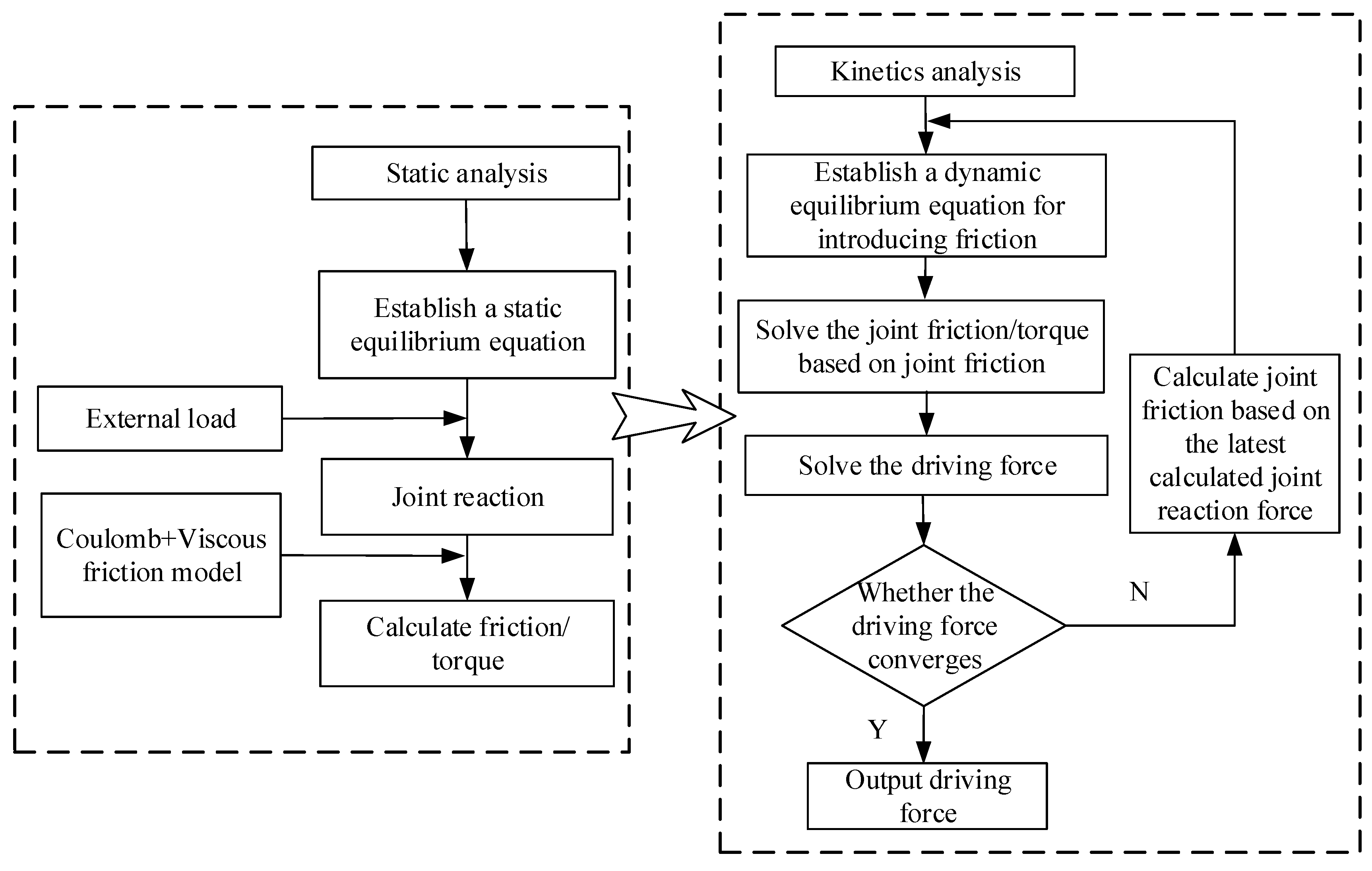
To overcome these challenges, this paper integrates the static mechanics-based “Disassembly Method of Static Mechanics” with a “Coulomb + Viscous” friction model. Firstly, static analysis is employed to precisely compute the joint reaction forces in any given pose, providing the necessary prerequisite for accurate friction calculation. Subsequently, a complete dynamic model incorporating friction is constructed on this basis. This approach remedies the deficiency of traditional methods (like the principle of virtual work) in determining joint reactions and, while ensuring model accuracy, avoids the complexity issues associated with methods like the Lagrangian formulation when friction is introduced. Addressing the real-time requirements of optical machining, this paper designs a feedforward-based PD friction compensator grounded in the aforementioned high-precision dynamic model. The core of this strategy lies in utilizing the model to pre-calculate frictional disturbances and cancel them out through the feedforward channel. This method offers high computational efficiency and ease of implementation, making it more suitable for industrial machining scenarios requiring prolonged stable operation. The research methodology and technical roadmap of this paper are illustrated in
Figure 1.
2. Kinematic Analysis
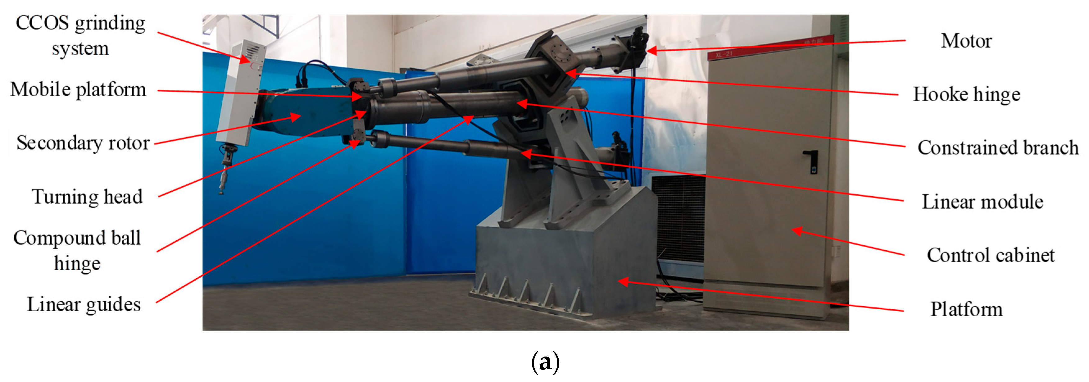
The prototype and topology diagram of the LOMP robot are shown in
Figure 2a,b, respectively.
α,
β, and
γ are used to represent the RPY angle of the moving platform
o-uvw with respect to
x,
y,
z in the fixed coordinate system
O-XYZ, and the attitude vector can be expressed as
. The relationship between
and the angular velocity
is given by Equation (1).
where
(simplified representation of
,
is applied in the formula).
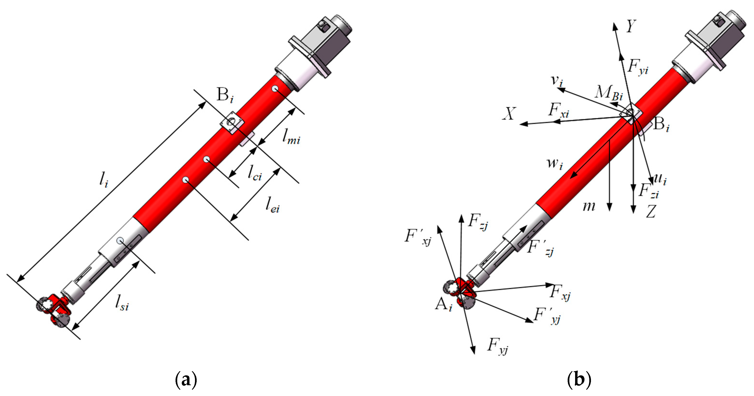
The closed-loop vector of the limb B
iA
i is given by Equation (2).
where
is the length of the branched B
iA
i,
R is the attitude matrix of the
o-uvw relative to
O-XYZ,
and
are the position vectors of the point
Ai and
Bi, and
is the position vector of the moving platform center.
The position
, velocity
, and acceleration
of point A in the coordinate system
O-XYZ are given by Equation (3).
The length of the drive branch
, the expansion speed
, and the expansion acceleration
are given by Equation (4).
The angular velocity
and the angular acceleration
of the driving branch are given by Equation (5).
The centroid velocity
and the centroid acceleration
ai of the driving branch are given by Equation (6).
The mechanism driving the Jacobian matrix can be further calculated as given by Equation (7).
The pose of the driving limb B
iA
iwith respect to the reference frame
O-XYZ is given by Equation (8).
where
and
denote the rotation angles about the
X-axis and
Y-axis, respectively,
.
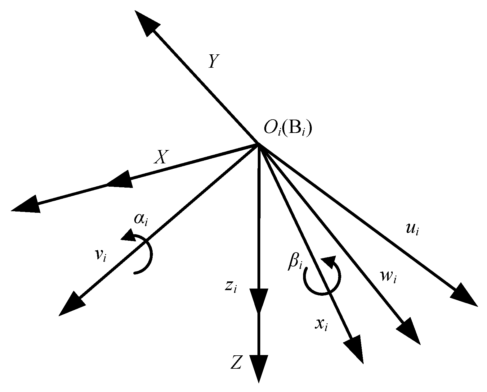
The orientation angles of the limb B
iA
i are given by Equation (9), and the active branch gesture vector is shown in
Figure 3.
4. “Coulomb + Viscous” Friction Model
The mathematical expression of the Coulomb + Viscous model is given by Equation (17).
where
v is the relative sliding speed,
is the viscous friction coefficient,
is the coulomb friction, and
is the sign function.
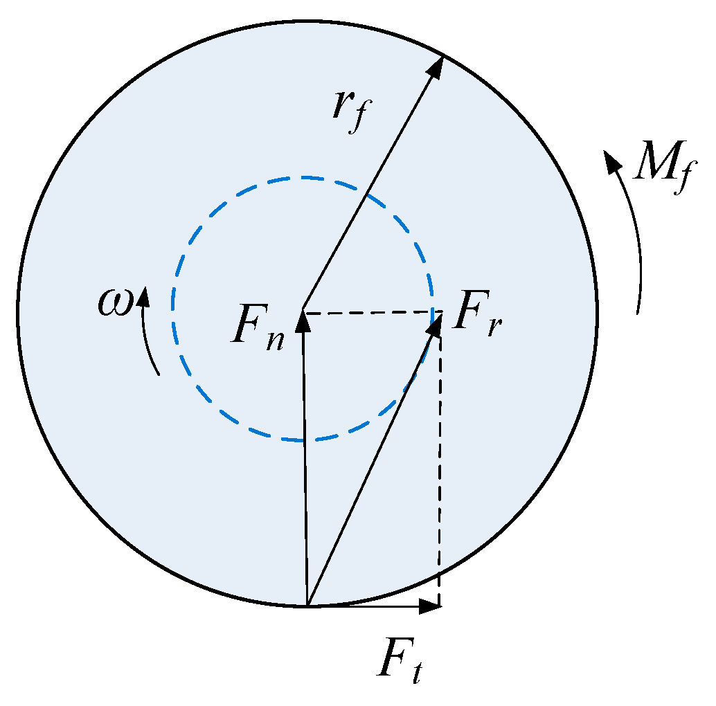
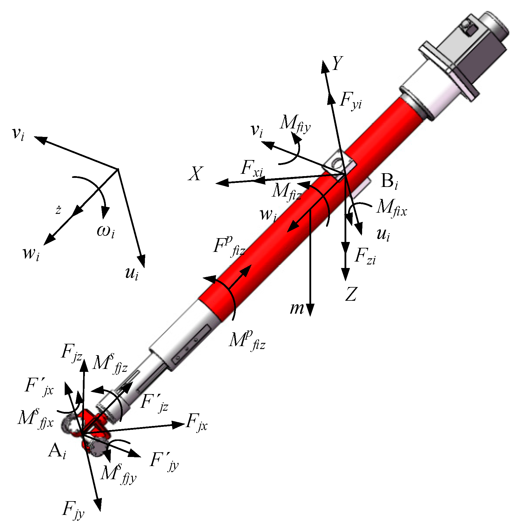
The friction torques introduced by the rotating pair are shown in
Figure 7, where
rf is the radius of the rotating pair,
is the angular velocity, and
is the friction torques,
is the normal force at the revolute joint,
is the tangential force, and
is the resultant force of the normal and tangential forces, which is always tangent to the friction circle.
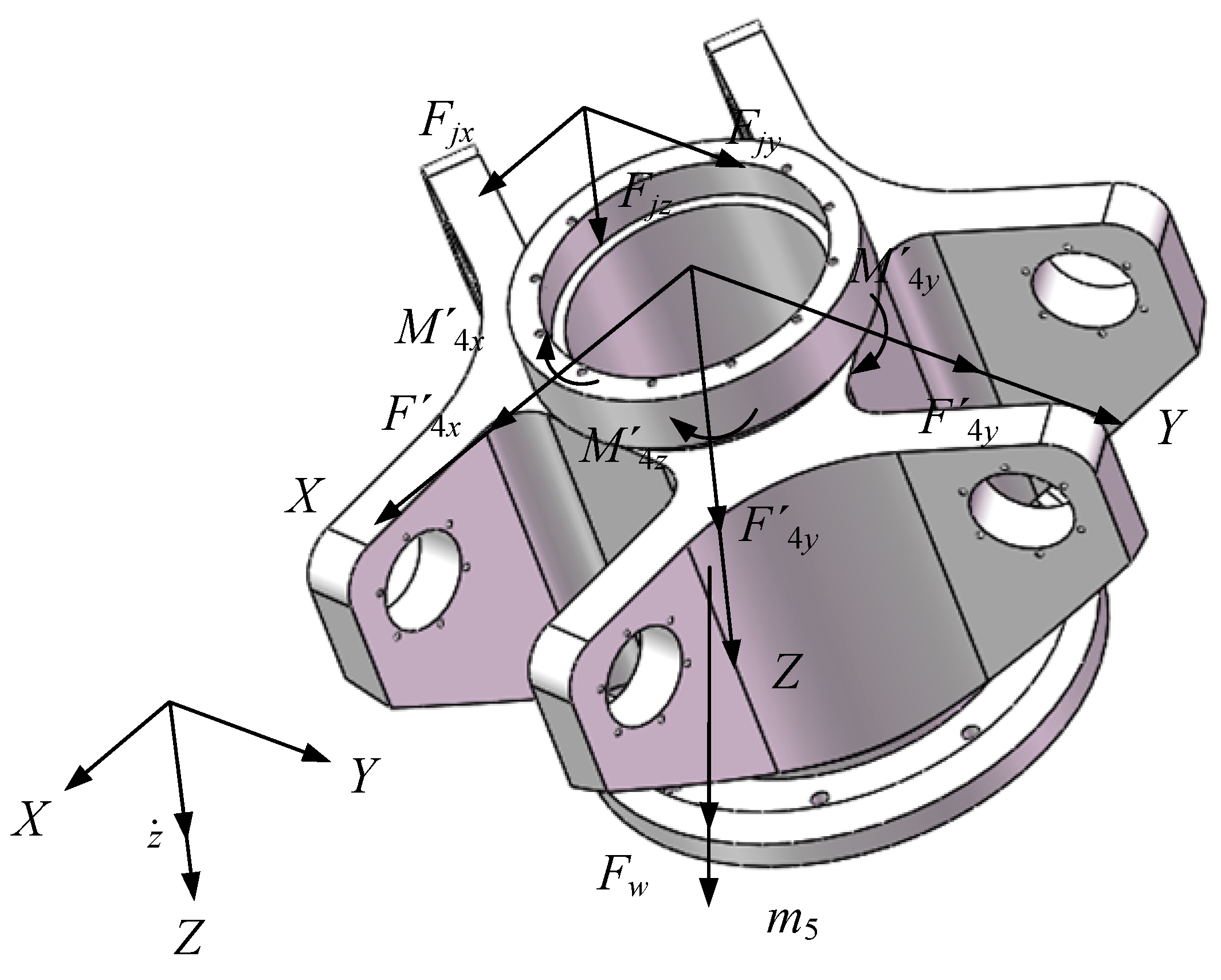
(1) The frictional torque in the Hooke’s joint is given by Equation (18).
where
are the joint reaction forces of the Hooke hinge,
is the viscous friction coefficient,
is the coulomb friction coefficient,
is the friction radius,
and
are the rotation speeds around the
X-axis and
Y-axis, respectively.
(2) The frictional torque in the ball hinge is given by Equation (19).
where
are the joint reaction forces of the composite ball hinge,
is the friction circle radius, and
,
, and
are the rotation speeds around the
X-axis,
Y-axis, and
Z-axis, respectively.
(3) The frictional torque and friction forces in the ball screw are given by Equation (20).
where
are the joint reaction forces of the linear module,
is the friction circle radius,
is the rotation speed around
Z-axis, and
is the movement speed.
(4) The frictional forces in the linear guide are given by Equation (21).
where
are the joint reaction forces of the linear guide, and
is the speed.
6. Joint Friction Compensation Based on Feedforward PD Control
When the parallel mechanism completes the task of space transportation, there will be frictions between the various kinematic pairs of the parallel mechanism. Since the working process of the LOMP robot is determined during the working process, the corresponding processing trajectory is also determined correspondingly. So, the motion state of the robot becomes known.
The friction torques model is given by Equation (28).
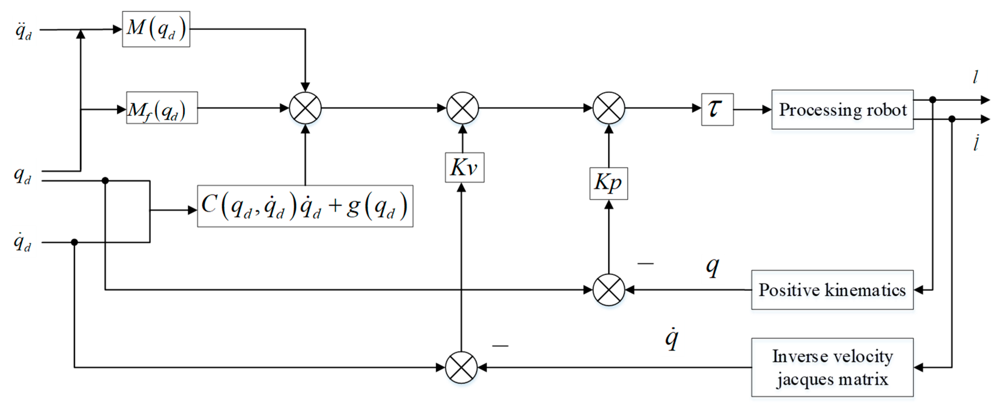
The feedforward PD control is given by Equation (29).
Among them,
is the inertia matrix.
are the centrifugal forces and coriolis forces.
is the gravity term.
,
,
, and
are the positive definite symmetry matrix parameters.
A block diagram of the robot control system using feedforward PD control is shown in
Figure 15.
The closed-loop equation is given by Equation (30).
The optimal PD control parameters for the robot, obtained through simulation analysis in MATLAB (R2022b)/Simulink, are given by Equation (31).
The simulation results are shown in
Figure 16. The results demonstrate that the feedforward PD control enables the robot’s trajectory to more closely align with the desired trajectory. In order to verify the reliability of parameters, the “Coulomb + Viscous” friction compensation speed control experiment with the LOMP robot was conducted based on the current loop. In this control system, the motion control card employed was the IMAC motion controller from Delta Tau, which is based on a DSP kernel and communicates with the host computer via an Ethernet port. Both the control and compensation algorithms were developed using the Pewin32 Pro2 software environment, executed on the host computer. This setup facilitates the issuance of control commands to the controller and the retrieval of collected control and feedback data from it. The desired motion trajectory of the processing robot is shown in Equation (27).
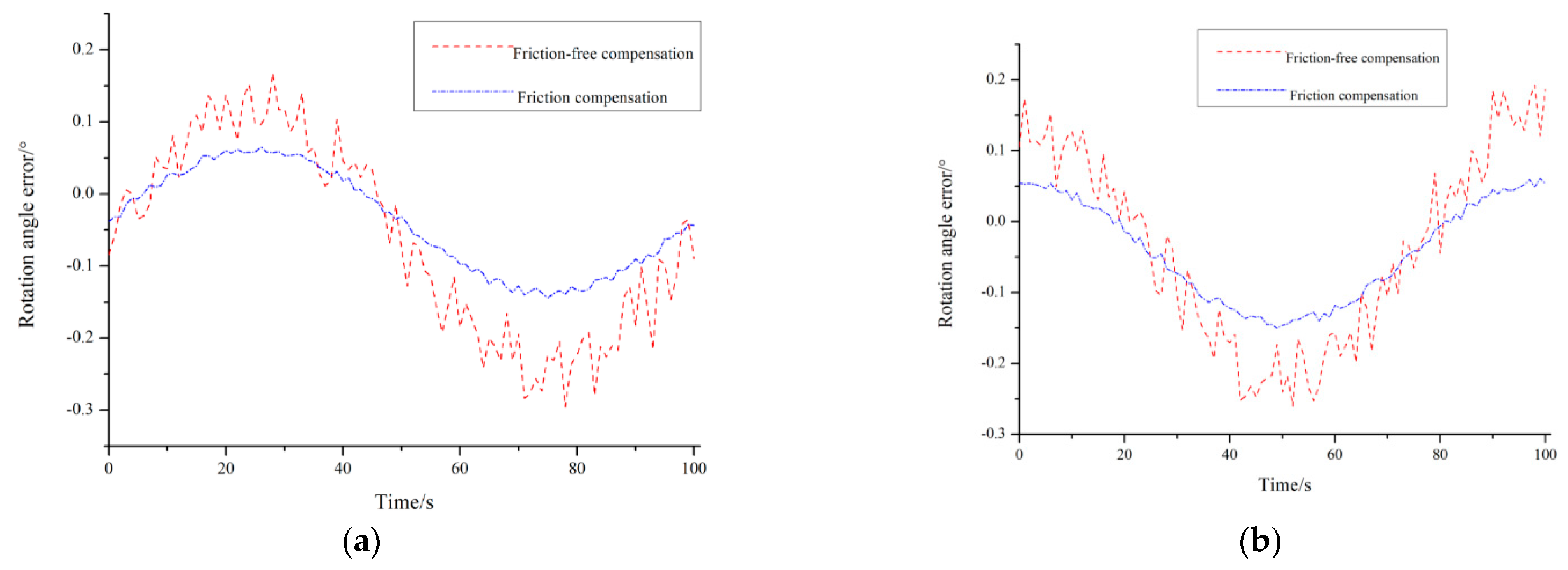
As shown in
Figure 17, the measured rotational angle error of the driving branch output torque demonstrates that without friction compensation, the moving platform’s rotational angle significantly deviates from the theoretical value. After applying compensation based on the established “Coulomb + Viscous” friction model, the tracking errors around the
X- and
Y-axis were reduced from 0.295° and 0.286° to 0.134° and 0.128°, respectively. These results confirm that the designed compensator can effectively mitigate the real-time friction effects during mechanism motion.
7. Discussion
This section aims to provide an in-depth analysis of key simulation and experimental results to elucidate their underlying physical mechanisms and engineering implications.
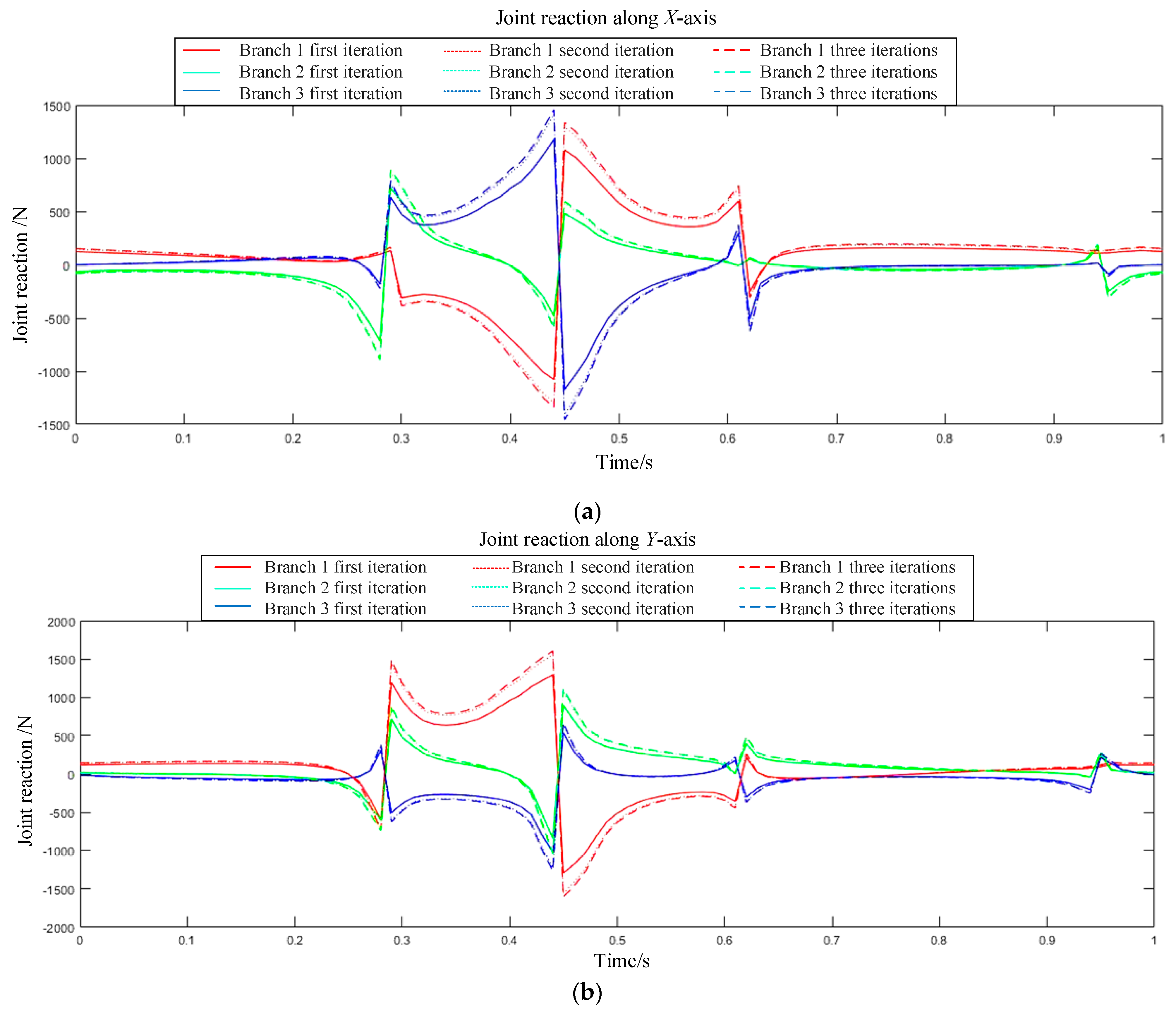
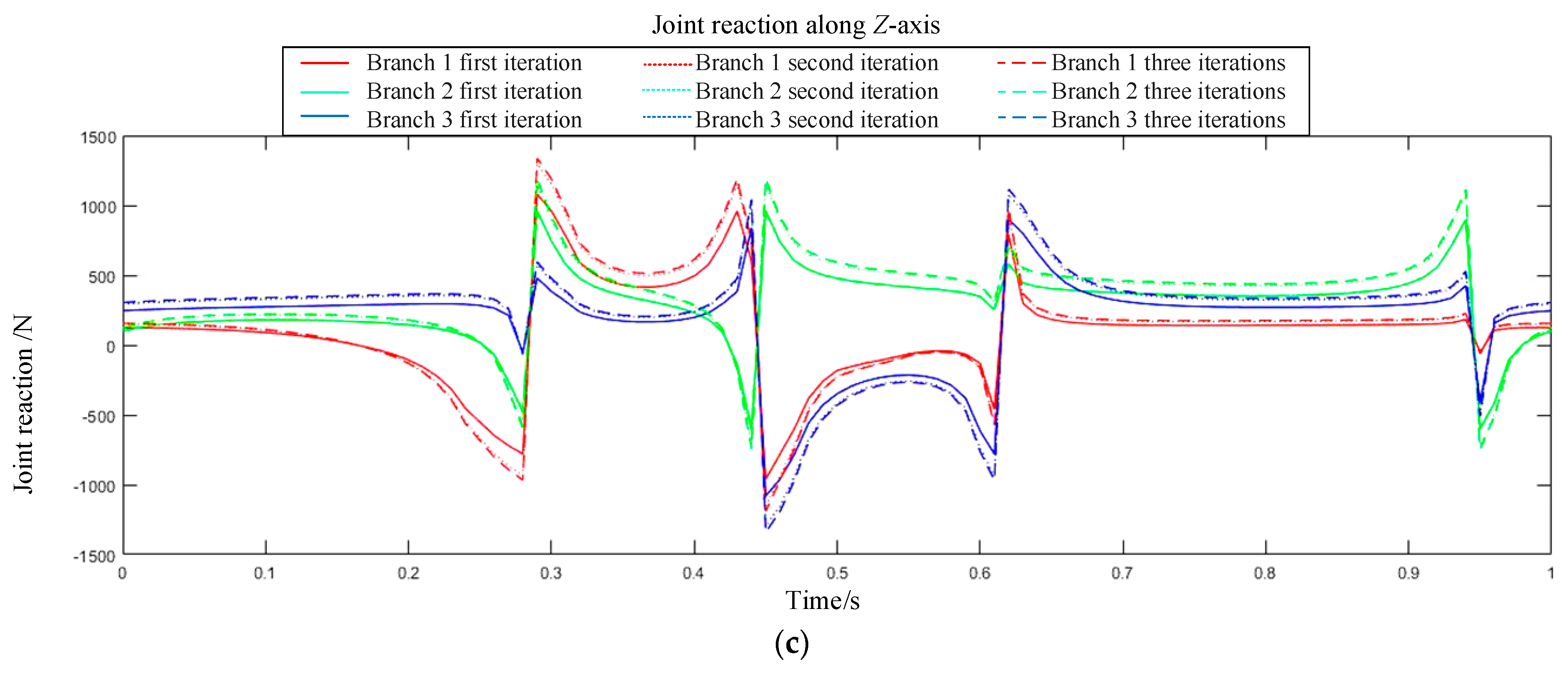
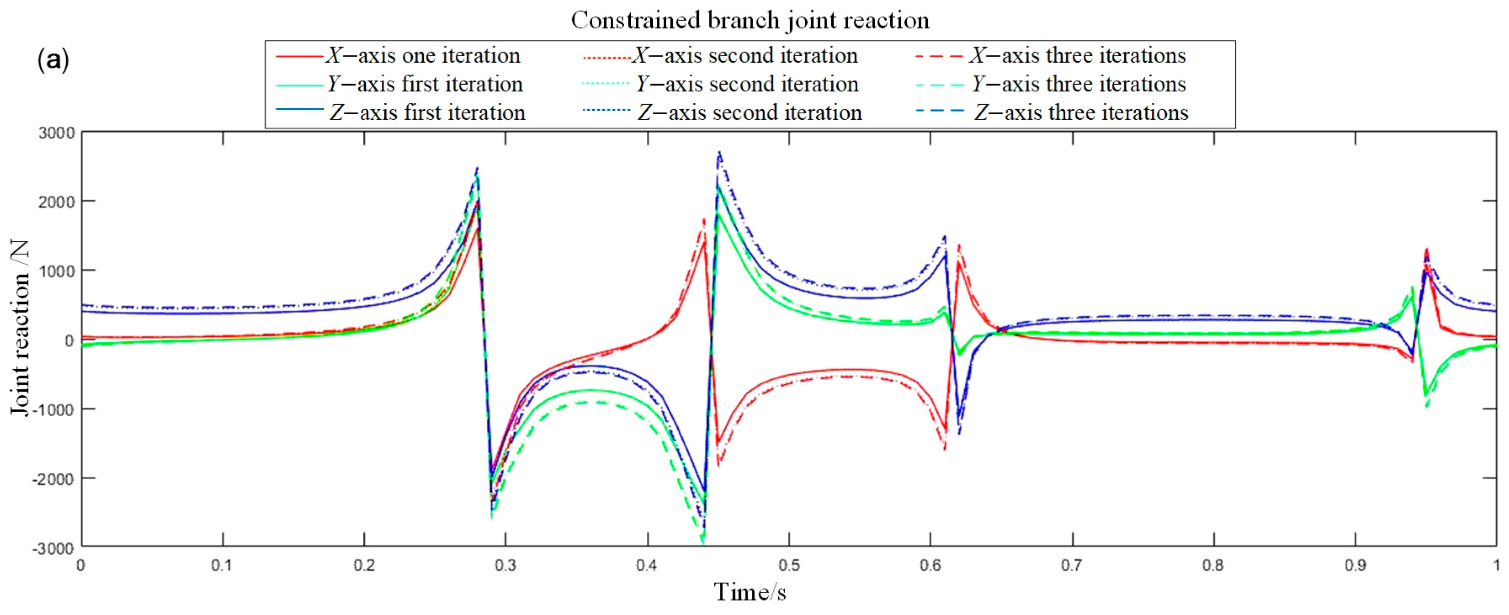
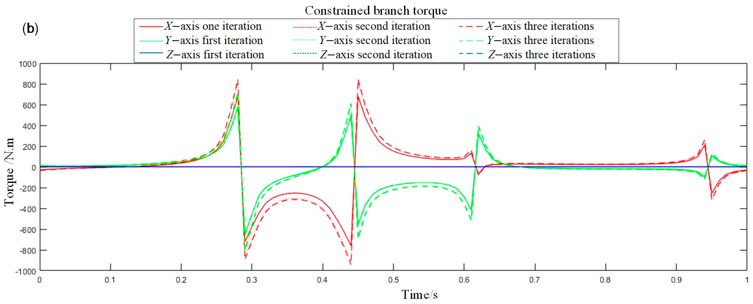
(1) The simulation results clearly demonstrate the substantial impact of joint friction on the system’s dynamic loads. When friction is considered, both the joint reaction forces and driving forces exhibit sharp peaks at motion reversal instants, with a maximum observed increase of 350 N. This phenomenon originates from the nonlinear step-change characteristic of the friction model at velocity zero-crossings. The resulting dynamic shock loads are significantly higher than those predicted by friction-neglected models. This finding underscores that traditional design methods based on idealized models systematically underestimate the actual loads on critical components, thereby imposing stricter requirements on structural reliability design and actuator selection for the robot.
(2) The feedforward PD compensator, designed based on the aforementioned high-precision model, successfully reduced the moving platform’s rotational tracking error by approximately 55%. This validates the effectiveness of the technical pathway: “solving joint reactions via static analysis—accurate friction calculation—feedforward compensation”. The principal advantage of this method lies in its feedforward nature, which enables the proactive cancellation of dominant disturbances and thus avoids the inherent latency issues associated with purely feedback-based control.
(3) However, the residual errors persisting after compensation also delineate the boundaries of the present model. These errors may stem from unmodeled dynamic coupling, component flexibility, or more complex friction behaviors (such as the Stribeck effect). This observation precisely indicates that the proposed framework—integrating the “Coulomb + Viscous” model with static analysis—successfully captures the primary factors governing system accuracy. Furthermore, it establishes a reliable research foundation for subsequent integration of more sophisticated models (e.g., flexible-body dynamics, adaptive control) in the pursuit of ultimate precision.
8. Conclusions
This study focuses on enhancing the accuracy of processing large optical mirrors by establishing a high-precision dynamic model that accounts for joint friction in a hybrid robot used for LOMP. And, a feedforward compensation control strategy based on this dynamic model is also designed. Compared to conventional dynamic models that neglect friction, the “Coulomb + Viscous” friction model developed in this work more accurately simulates dynamic loads at critical points such as motion direction reversals, revealing significant abrupt changes in joint reaction forces and driving forces under such conditions. Experimental results demonstrate that the friction compensator, designed based on the proposed model, effectively reduces force output errors caused by joint friction, thereby laying a solid foundation for directly improving the robot’s end-effector trajectory accuracy and repeatability.
This research provides a dynamics-based solution for improving the quality of LOMP. By actively compensating for internal frictional disturbances, the uncertainty in the machining process is reduced. This approach decreases the number of traditional “polishing–inspection–polishing” cycles required during LOMP, saving time associated with fixture positioning for inspection and re-positioning for polishing. The study establishes a reliable research foundation for achieving high-precision, efficient processing of large optical mirrors, particularly those with complex or freeform surfaces.
Although this work investigates the dynamics of a LOMP robot with joint friction, it does not account for time-varying effects. Given the extended duration of the LOMP cycle, prolonged and uninterrupted operation will inevitably lead to phenomena such as frictional wear and fatigue. Therefore, future research should account for time-varying parameters, such as the friction coefficient and link mass. This necessitates the development of online parameter identification algorithms or adaptive/robust control strategies to maintain high system performance in the presence of such parameter fluctuations.

