1. Introduction
As an essential type of supporting component, the aerodynamic foil thrust bearing (FTB) exhibits high reliability at high operating speeds [
1], good adaptability to variable speeds [
2], low friction [
3], and no risk of contamination [
4]. It plays a crucial role in the engineering field, such as small gas turbines [
5], turbo-expanders [
6], turbochargers [
7,
8], and other rotating equipment [
9]. The dynamic characteristics of FTBs are critical to operational stability and have therefore attracted considerable research attention.
Generally, FTBs can be classified into three types: bump foil [
10,
11], protuberant foil [
12,
13], and viscoelastic-supporting foil [
2]. However, the continued improvement of their operational performance is challenged by high design complexity and high-precision manufacturing requirements. Consequently, parametric and structural optimization of FTBs has become a focus of research [
14,
15].
Fortunately, a convex wedge-shaped clearance can effectively enhance bearing capacity compared to concave or plane wedges [
16,
17]. Furthermore, the introduction of multi-layer foils has enabled both high bearing capacity and simple assembly [
18,
19], creating promising prospects for practical applications. This has led to widespread interest in multi-layer foil thrust bearing (MLFTB) [
20,
21].
The parameter effects on bearing performance have been extensively studied. Iordanoff [
22] numerically investigated how clearance affects load capacity, using an empirical formula to effectively describe foil deformation. This study highlighted the significant impact of original clearance on bearing capacity, but the effects of clearance on dynamic characteristics require further exploration. Feng et al. [
23] proposed a link-spring structure to determine the vertical stiffness of bump foils, incorporating both foil elasticity and inter-foil friction into their model. They found that algebraic simplification enabled easy programming of the numerical model while maintaining accuracy and efficiency. However, this work focused on bump-type gas foil thrust bearings (GFTBs), leaving numerical studies on the MLFTB underdeveloped. During numerical investigation of foil bearings, Larsen [
24] emphasized that both simplicity of programming and ease of implementation are critical for model improvement. This insight provides valuable direction for advancing numerical models, specifically, more efficient and effective models for the dynamic characteristics of the MLFTB are urgently needed. Shi et al. [
25] established a 3-degree-of-freedom (3-DOF) dynamic characteristics model for FTBs and the significant effects of bearing speed and perturbation frequency. However, this model targeted aerostatic thrust bearings (ATBs), and research on aerodynamic types (e.g., MLFTBs) remains insufficient. Later, Chen et al. [
26] established a dynamic characteristics model for a swing-pad FTB and discussed how disturbances affect thrust load. Despite these efforts, the effects of parameters on bearing dynamic characteristics still need to be clarified.
Using the NASTRAN solver, Zhang et al. [
27] calculated the distributed foil deformation of MLFTBs. By comparing MLFTBs with the GFTBs, they found that multi-layer components offer better adaptability to variable loads and significantly reduce the risk of rub and abrasion. Later, Dou et al. [
28] established a foil thrust bearing model based on link-spring and the thin-plate theories, investigating how operational parameters affect dynamic characteristics. They concluded that the adaptive deformation of foils helps prevent dry friction, thus providing valuable numerical insights into dynamic behavior. However, this study used liquid nitrogen as the lubricant under ultra-low ambient temperatures, and research on gas-lubricated MLFTBs remains limited. Meanwhile, Xu et al. [
29] proposed models for MLFTBs and validated them by comparing simulated and experimental results. They demonstrated that a simplified model can achieve both high precision and efficiency with appropriate modifications. However, this model was most effective under heavy bearing loads (a focus on static characteristics), and the research on dynamic characteristics still requires further improvement.
Notably, the high-velocity flow of lubricating gas in the micrometer-scale wedge-shaped clearance of MLFTBs may induce the boundary slip effects, which should be considered in research. Several studies have focused on slip flow, with boundary slip effects being a key area of interest [
29,
30,
31]. Bruckner et al. [
30] introduced the Knudsen (
Kn) number to predict the aerodynamic performance of the FTBs. Subsequently, Park et al. [
31] incorporated a rarefaction coefficient into their bearing analysis. Jiang et al. [
32,
33] developed the multiscale models for foil bearings, predicting and discussing the effects of high-Knudsen conditions (
Kn > 0.1). They later investigated how boundary slip affects the static characteristics of MLFTBs, finding that boundary slip can negatively impact bearing capacity under small clearance and low bearing speeds, thus highlighting the need to account for this effect. However, investigation on the relationship between the boundary slip effects and the dynamic characteristics (under fluid–structure interactions) remains underdeveloped.
In addition to numerical studies, several experimental investigations of dynamic characteristics have been reported. Lim et al. [
34] experimentally determined the force coefficients of ATBs, finding that negative damping coefficients can cause pneumatic hammer instability. Later, Dykas [
35] experimentally verified that variations in wedge-shaped clearance parameters strongly affect the bearing capacity. Yu et al. [
36] validated their model’s predicted thrust forces under different bearing parameters through experiments. However, on account of the challenges of test rig design, high experimental costs, and strict experimental conditions, most experiments have only been used to validate numerical models. Few studies have explored the relationships between parameter effects and dynamic characteristics, especially when considering the boundary slip effect, and the underlying elasto-hydrodynamic mechanisms require further discussion.
Under other FTB types, MLFTBs have more complex deformation behavior, leading to distinct characteristic coefficients, especially under boundary slip effects, which remain unclear. Previous studies have primarily been concerned about the lubrication characteristics of gas under different parameters, leaving a gap in the understanding of the MLFTB dynamic characteristics. Additionally, some existing dynamic models are computationally expensive and have limited precision. There is therefore an urgent need to develop high-accuracy, computationally efficient, and easily programmable dynamic characteristics models for MLFTBs. Further research on the underlying elasto-hydrodynamic mechanisms of dynamic characteristics is also essential for MLFTB design.
In this research, a modified dynamic characteristics model for MLFTBs is established. The modified compressible Reynolds equation (incorporating boundary slip) is solved using the Newton–Raphson method and the small perturbation method. The influences of geometric and operational parameters on the variation in dynamic characteristics are derived iteratively, with the boundary slip effect considered. The results show that accounting for boundary slip can reduce the axial and direct-rotational stiffness coefficients by up to −4.93% and −5.02%, respectively, indicating that this effect cannot be neglected. Additionally, the dynamic characteristics of MLFTBs are only slightly influenced by the comprehensive structural damping, demonstrating good operational stability. Comparative analysis confirms that the proposed model can predict MLFTB dynamic characteristics with high efficiency and satisfactory accuracy. This work aims to provide theoretical guidance for the design and optimization of MLFTBs.
2. Numerical Models
The schematic diagram of the top foil and supporting panel of MLFTB is presented in
Figure 1. For the mathematical modeling of the MLFTB, a Reynolds equation coupled with the thick plate element and boundary slip model was derived via the finite difference method (FDM). In the current calculation process, two key numerical methods were employed: the Newton–Raphson method [
37] and the small perturbation method. This work serves as a follow-up study to the previous investigation on the static characteristics of MLFTBs [
33]. Leveraging the established numerical model, the influences of the geometric and operational parameters on the axial, direct-rotational, and cross-rotational stiffness and damping coefficients can be predicted.
2.1. Reynolds Equation
In this study, the lubricating medium is assumed to be an isothermal ideal gas, a simplification consistent with typical aerodynamic bearing analyses [
29]. To predict the lubrication pressure distributions within the MLFTB, a dimensionless compressible Reynolds equation was derived, and is expressed as follows [
29]:
where
where
is the surface and the accommodation coefficient, and
is the tangential momentum accommodation coefficient, describing the slip behavior at the gas–solid interface.
represents the Knudsen number that characterizes the rarefaction effect of the lubricating gas. It incorporates fundamental thermodynamic and geometric parameters.
Comprehensively, is defined by the reference temperature , the ambient pressure , the supporting plate height , and the gas constant . represents the specific gas constant, and for air, it exists as ).
The dimensionless Reynolds equation integrates the thick plate element deformation effect and boundary slip effect, enabling accurate prediction of the pressure field under rarefied gas lubrication conditions.
2.2. Gas Film Thickness Equation
The expression for the dimensionless gas film thickness
can be written as
where,
represents the original thickness, and
is the axial foil deformation. As for MLFTB, the geometric relationship of the foil arch satisfies the following expression:
Herein, represents the pitch of the foil arch, represents the flare angle of the shell sector, and represents the folding and flare angle of the sector. represents the radial radius (i = 1 and i = 2 are the inner and outer radii, respectively). Based on Formula (4), the distributed height of a single sector can be derived for a given foil arch pitch ht0.
Leveraging the thick plate element theory [
38,
39], finite element models (FEMs) of MLFTB components, which include the top and middle foil as well as the supporting panels, were established, as schematically depicted in
Figure 2 [
33]. The thick plate element was selected for its ability to accurately capture the bending and deformation behavior of the foils.
In practical finite element modeling of the MLFTB foils, the stiffness is generally decomposed into the bending stiffness
and the shear stiffness
, where the total stiffness matrix
can be expressed as the sum of these two components:
where the bending stiffness matrix
accounts for the resistance of the foil to bending deformation. This is calculated via integration over the element area
as follows:
Meanwhile, the shear stiffness matrix
captures the foil’s resistance to shear deformation, with the integral form given by
where the bending strain matrix
for the thick plate element is a block matrix composed of submatrices corresponding to each node of the element, can be written as
For the MLFTB, the foils are assumed to be parallelly jointed. Based on this assumption, the overall stiffness matrix of the foil assembly is established using a linear system of equations [
39]:
Herein, , (i = 1, 2, …); it is concerned with each node’s lubrication pressure. , , (i = 1, 2, …) and is in relation to each node’s movement. With the extraction of the lateral shift , the foil’s deformation will be derived.
2.3. The Solution Processes of the Dynamic Characteristics
When the shaft rotates steadily at the angular velocity ω, the equilibrium position of the MLFTB is defined as . Once a small perturbation occurs around this equilibrium position, the axial displacement, velocity, as well as acceleration are denoted as , and , respectively. For rotational motions, the displacements, velocities, and accelerations around the x-axis and y-axis are defined as , , ; and , , , respectively.
To simplify the dynamic analysis, the aforementioned perturbation variables are converted to dimensionless forms using the characteristic length
and outer radius
of the bearing can be written in the dimensionless forms as
where
represents the dimensionless time, and it exists
. By the derivation of Formula (10) with respect to
, the expressions of perturbation velocities and accelerations can be transferred as follows:
Through the Taylor expansion, the dimensionless pressure
, film thickness
, as well as the foil deformation
of the balanced position
,
, and
are
where
,
, and similar definitions apply to
and
.
Substituting the Formula (13) Taylor expansion into the dimensionless Formula (1) Reynolds equation, upon simplifying and sorting out, the formulas are as follows:
Formula (14) is the steady-state pressure-governing equation, and Formulas (15) and (16) are axial perturbation governing equations that concern perturbation pressures and , perturbations of film thicknesses and in the axial direction. In addition, Formulas (17) and (18) are the rotational governing equations (x-axis) concerning the perturbation pressures and and perturbations of film thicknesses and . Additionally, Formulas (19) and (20) are the rotational governing equations (y-axis) concerning the perturbation pressures and , as well as perturbations of film thicknesses and .
2.4. Relationship Between Thickness and Pressure
Under actual operating conditions, when the perturbations
,
, and
occur on the thrust disc around the equilibrium position
, the nondimensional film thickness needs to be updated to account for the rotational perturbation effects. The modified equation, Formula (3), can be expressed with Formula (21):
Through the Taylor expansion of Equation (13), simplifying and it will be expressed as
By introducing Formula (13), the dimensionless foil deformation equation, Formula (23), can be derived:
Each of
and
represents the nondimensional foil stiffness matrix and damping matrix, respectively, and
represents the nondimensional pressure matrix.
where
is the so-called comprehensive structural damping of the foils.
is the characteristic area of the bearing.
Considering the relationships of Formula (22), by substituting it into Formula (23) and combining it with the linearized Reynolds equation Formulas (15)–(20), in addition to processing, the following formulas can be derived:
where Formulas (25) and (26) correspond to the axial perturbation pressures
and
and film thicknesses
and
. Formulas (27) and (28) are related to the
x-axis perturbation pressures
and
, and film thicknesses
and
. Additionally, Formulas (29) and (30) are concerned with the
y-axis perturbation pressures
and
, and film thicknesses
and
.
Through integrating the perturbation pressures over the bearing’s active area, the dynamic coefficients can be derived. As for MLFTB, these deviations and solution procedures of the disturbance pressure and film thickness are identical to the bump-type multi-foil aerodynamic journal bearing’s [
40]. The dynamic coefficients of the fresh MLFTB are as follows:
where
and
are the stiffness and damping coefficients of MLFTB, respectively.
Moreover, the transition from nondimensional to dimensional can be made as follows:
Specifically,
and
are the direct stiffness and damping coefficients in the axial direction, respectively.
Specifically, each of and , as well as and , are the direct-rotational stiffness and damping coefficients at the x- and y-axis, respectively. In addition, and , as well as and , are the cross-rotational stiffness and damping coefficients, respectively.
2.5. Computation Procedure of Dynamic Characteristics
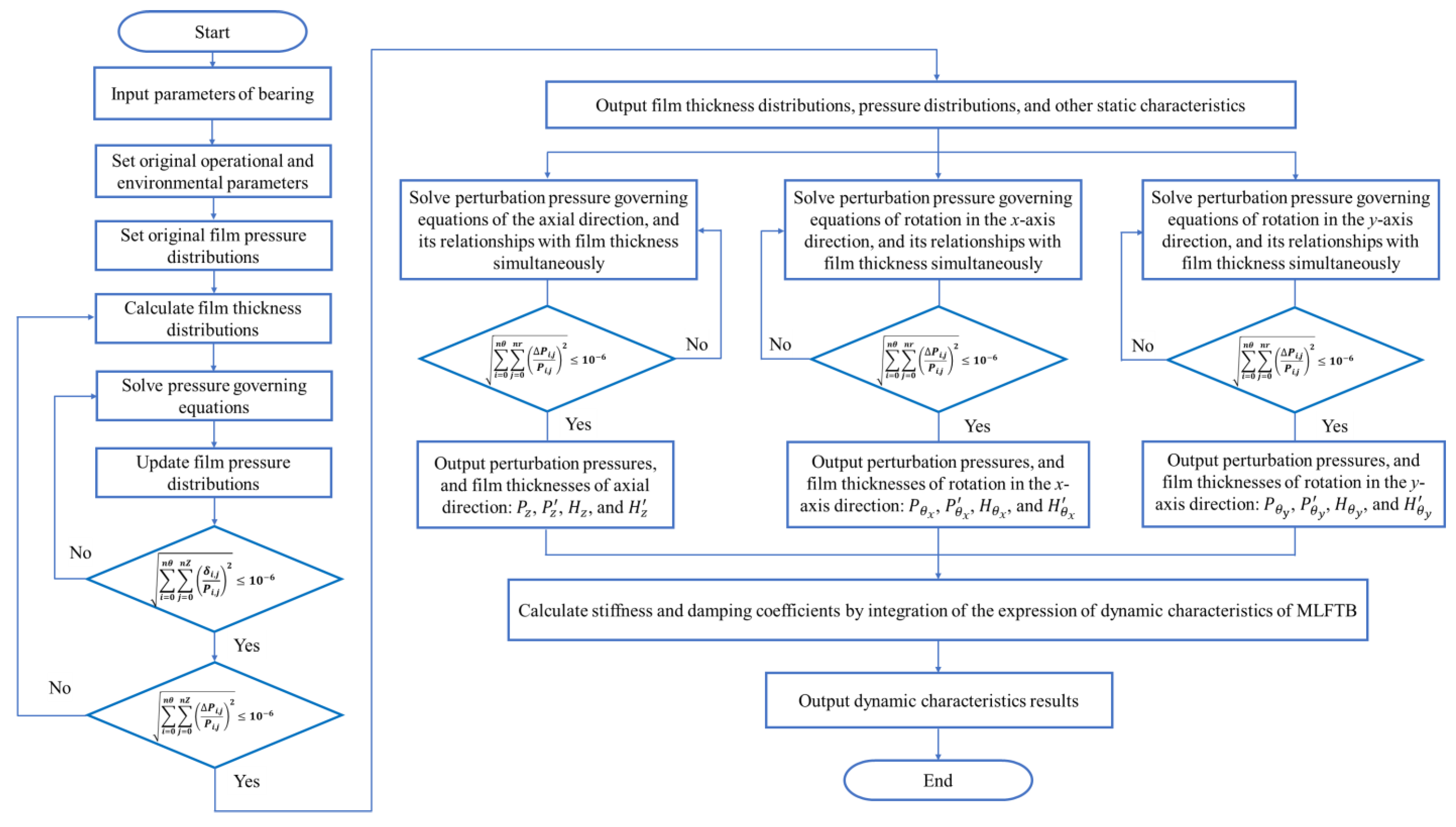
The solving procedure for the dynamic characteristics of MLFTB is schematically illustrated in
Figure 3. This procedure integrates the aforementioned mathematical models into a systematic iterative framework. Additionally, the schematic of the grid division and definition of the calculation domains are presented in
Figure 4 [
33]; these grids are used to discretize the bearing’s radial and circumferential domains, ensuring accurate numerical integration. After inputting the parameters, the static and the dynamic characteristics will be iteratively computed and estimated until the convergence criteria shown in Formula (42) are achieved. Thus, the dynamic characteristics of MLFTB will be derived.
The boundary conditions are specified in the following forms:
The convergence criteria are expressed in the following forms:
Specifically, the lubricating gas pressure, foil deflection, and bearing capacity can be adopted to judge the convergence situations.
where
is the residual pressure,
is the residual of deflection, and
is the residual bearing capacity. The subscript
represents the node coordinate, and the superscript k refers to the solve for the k times iteration. For instance,
represents the k times iterative solution of pressure at the node of
. Once all the residuals are less than 10
−6, it can be regarded as the convergence of the solution being achieved.
2.6. Verification of Model
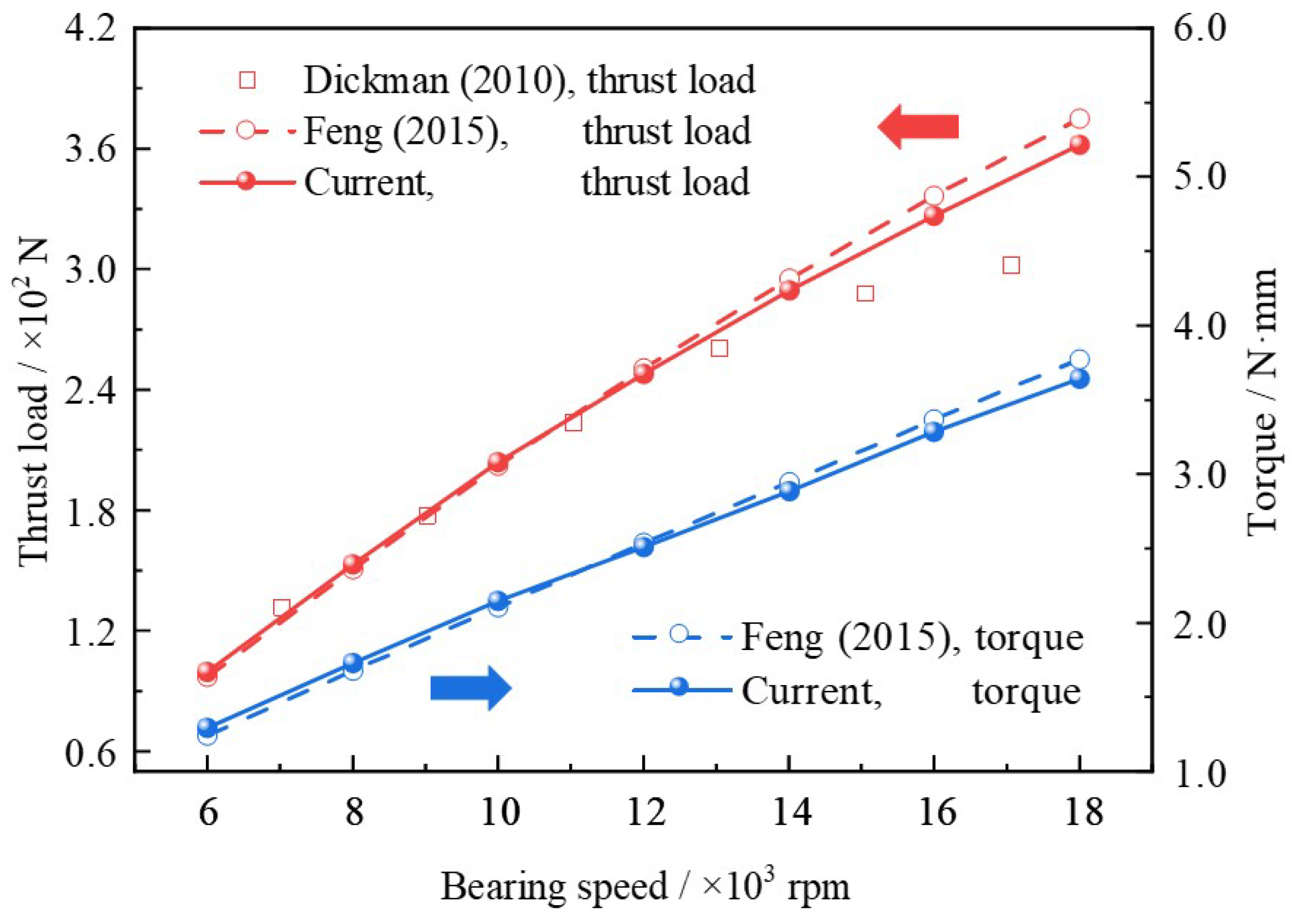
To prove the reliability and accuracy of the established MLFTB dynamic characteristics model, the calculated results were compared with two sets of reference data: the experimental data in the literature [
41] and the numerical results in the literature [
23]. The comparisons focus on key static performance indicators, bearing load and friction torque, since these parameters directly reflect the consistency between the model’s lubrication pressure and film thickness predictions and real-world behavior. The corresponding results are presented in
Figure 5, and both nondimensional bearing load
and nondimensional friction torque
were derived from the lubrication pressure and film thickness, with their calculations, Formulas (46) and (47), given by
As can be seen from
Figure 5, both the bearing load and friction torque almost linearly increase with rising bearing speed. This aligns with the physical expectation that higher speeds enhance the aerodynamic lubrication effect, increasing the pressure field and thus the bearing load, while also elevating viscous friction. When it is less than 1.4 × 10
4 rpm, the current results show high consistency with both the simulated results of literature [
23] and experimental results of the literature [
41]. When it exceeds 1.4 × 10
4 rpm, deviations emerge between the numerical results (current model and literature [
23]) and the experimental data [
41] appear: the experimental bearing load is lower than the numerical predictions. This discrepancy can be attributed to foil thermal deformation caused by thermal runaway of the test rig in the experiment [
41]—the elevated temperature deforms the foils, altering gas film thickness and decreasing the effective bearing load. Notably, neither the current model nor the numerical model in the literature [
23] incorporates thermal effects, leading to overprediction of bearing load at higher speeds. Further, the maximum deviation between the current model and the reported numerical results of literature [
23] is no more than 3.5%. Notably, in order to reproduce the situations, the calculated results are also derived under the conditions of the no-slip effect. Further, the influence of the slip effect also varies with the different geometric, operating, and physical property conditions. This small deviation, combined with the low-speed agreement with experimental data, confirms that the established MLFTB model possesses good dependability and effectiveness for predicting dynamic and static characteristics under isothermal conditions. It proves that the established model possesses good dependability and effectiveness.
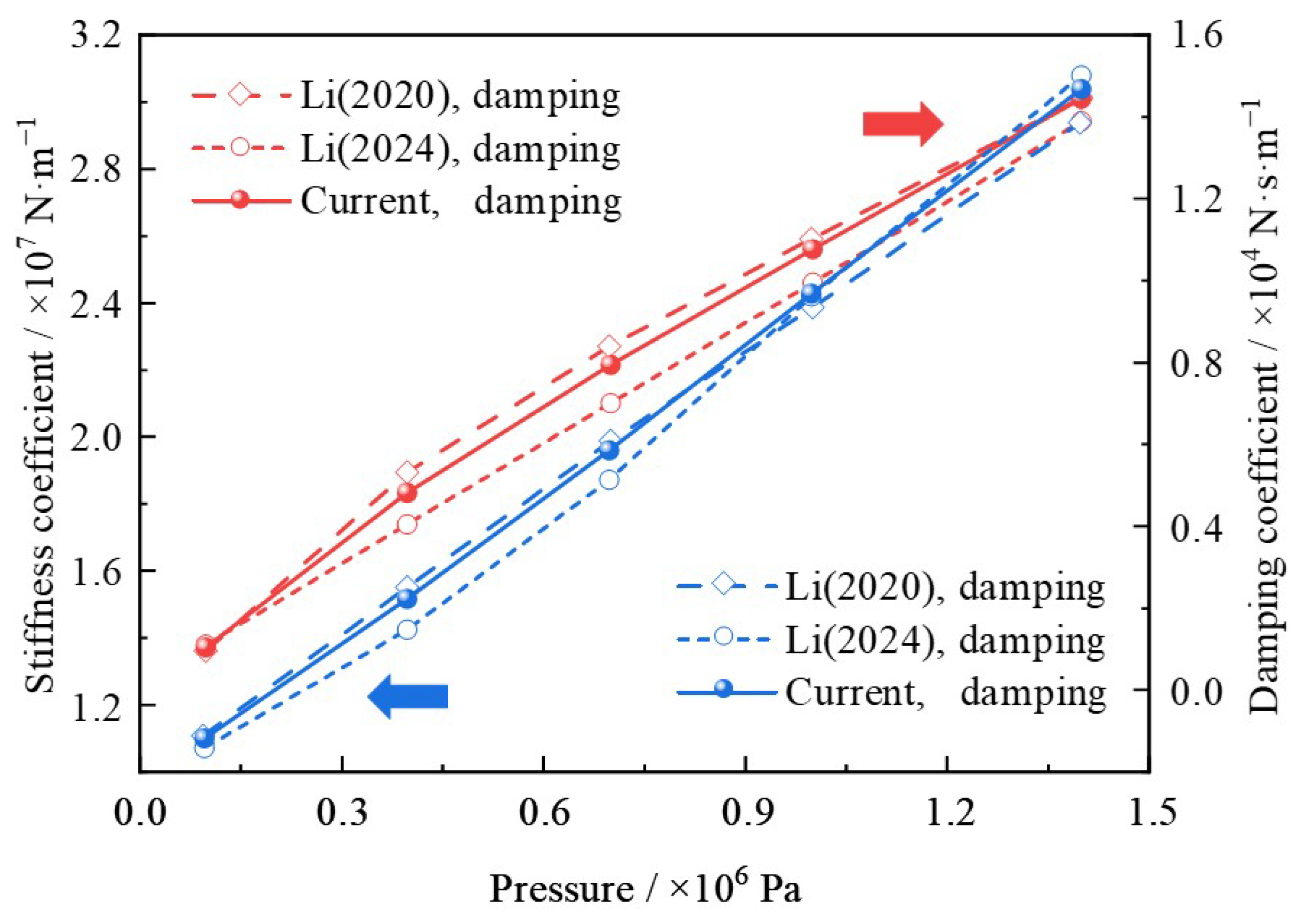
To further ascertain the validity of the current model, especially its accuracy in predicting dynamic characteristics, the simulated stiffness and damping coefficients were compared with the reported results from two independent studies: Li et al. (2020) [
42] and Li et al. (2024) [
43]. To ensure the fairness and reliability of the comparison, all geometric and environmental parameters in the current simulation were set identically to those reported in the literature [
42,
43]. The comparison results for stiffness and damping coefficients are depicted in
Figure 6. As can be seen from
Figure 6, the variation trends of the dynamic coefficients predicted by the current model are approximately identical to those reported in the literature [
42,
43]. It further demonstrates that the established model in the current research is credible with high accuracy.
The associated geometric, operational, and material parameters adopted for the subsequent sections of this research are listed in
Table 1. The parameters are selected from typical MLFTB configurations in engineering applications and cover a reasonable range to ensure the generality of the research conclusions.
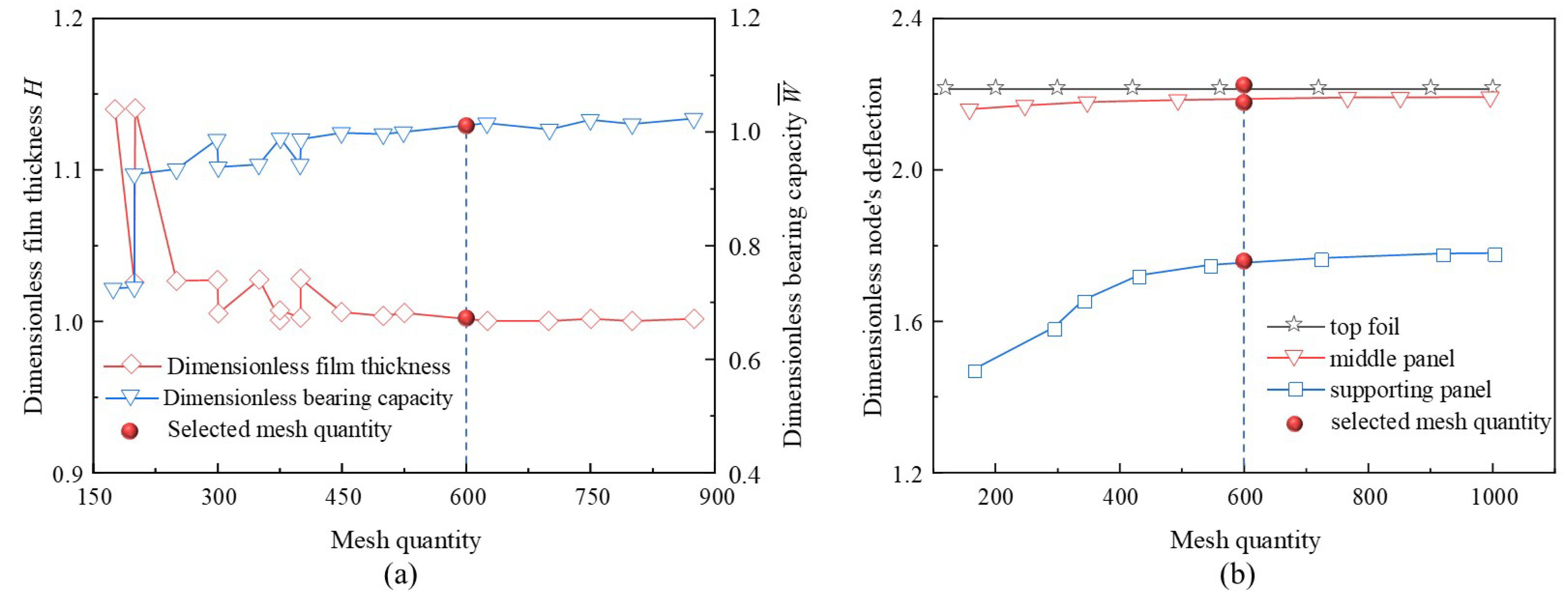
To reduce the influence of mesh division on numerical prediction accuracy and ensure the stability of the simulated results, a mesh independence analysis was conducted. Specifically, the static characteristics (e.g., film thickness and bearing capacity) and dynamic characteristics (node’s deflection) were predicted under different mesh quantities (radial nodes
multiply by circumferential nodes
), and the results are depicted in
Figure 7. Seen from
Figure 7, through verification of the mesh independence, the grid quantity was determined as
.
3. Results and Discussion
The influences of clearance, disturbance frequency, bearing speed, foil number, and comprehensive structural damping on the dynamic coefficients of MLFTBs are presented in Sections 3.1 to 3.5, respectively. Utilizing the boundary slip model, the effects of the slip phenomenon were explored and analyzed in detail. Through comparative analysis, it was observed that the stiffness coefficients , , , and and the damping coefficients , , , and are significantly smaller than the coefficients in other directions, and thus can be neglected in subsequent analyses. Therefore, the current research focuses primarily on the direct coefficients and cross-rotational coefficients. In addition, since MLFTBs exhibit symmetry along the θx and θy directions, the direct-rotational coefficients corresponding to these two directions are symmetric; in contrast, their cross-rotational coefficients show an antisymmetric characteristic.
3.1. Clearance
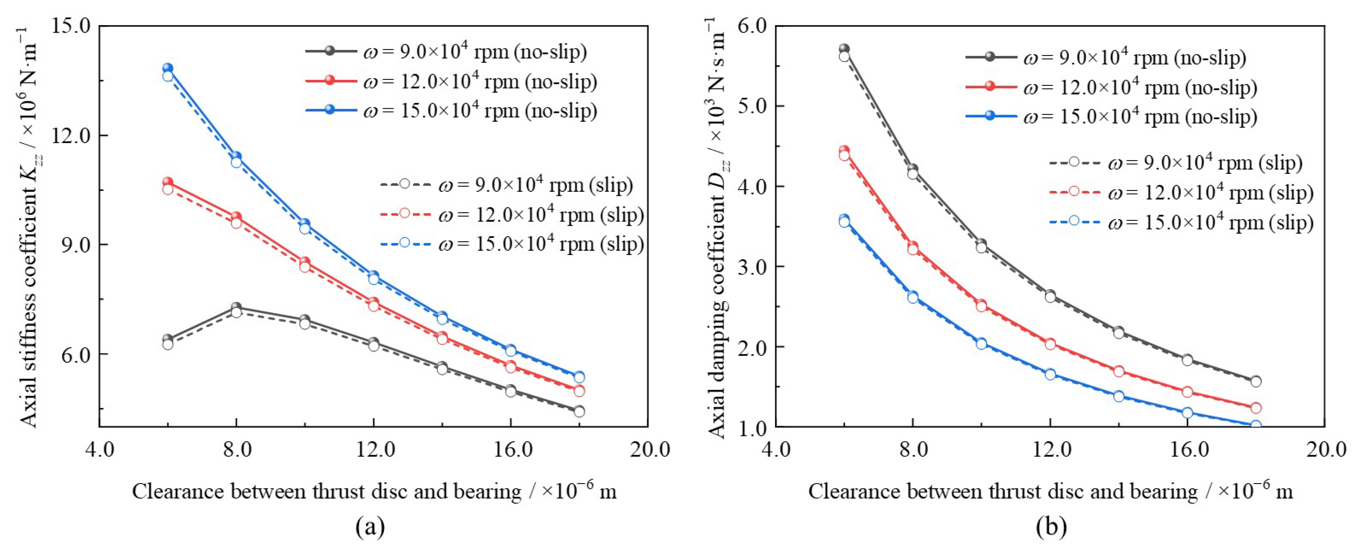
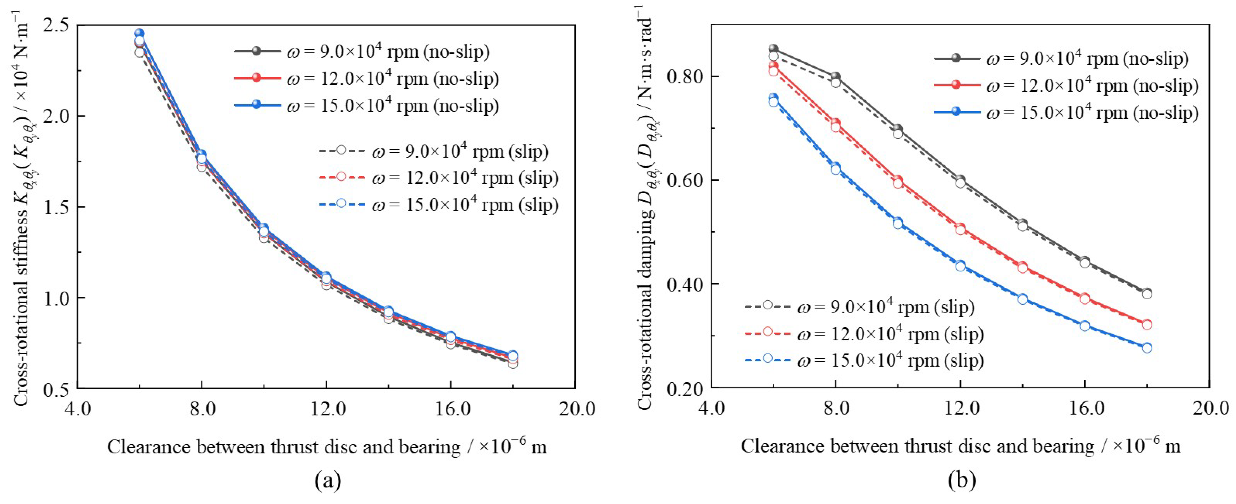
Primarily, as a critical parameter, the effect of clearance between the thrust disc and bearing on the dynamic coefficients was the focus of this section. The clearance was varied from hg0 = 6.0 × 10⁻⁶ m to hg0 = 18.0 × 10⁻⁶ m under different bearing speeds rising from ω = 9.0 × 10⁴ rpm to ω = 15.0 × 10⁴ rpm. Other key parameters were set as follows: foil number N = 12 and disturbance frequency ratio γ = 1.0. To better observe the variations in dynamic characteristics of MLFTBs, the distributions of axial coefficients, direct-rotational coefficients, and cross-rotational coefficients were predicted and presented in Figures 8, 9, and 11, respectively. Additionally, a comparison was conducted between the boundary slip and no-slip conditions.
As shown in
Figure 8, with clearance increasing, the axial stiffness and damping coefficients decreased overall. This trend is consistent with that of the GFTB in the literature [
23]. In contrast to the no-slip conditions, the coefficients under the slip effect were lower, and the differences between the two conditions narrowed at larger clearances. This phenomenon can be attributed to the reduced proportion of the slip boundary as the clearance increases. For
ω = 9.0 × 10
4 rpm, the maximum deviation in the axial stiffness coefficient was approximately −2.22% at
hg0 = 6.0 × 10
−6 m, while the minimum deviation was approximately −1.01% at
hg0 = 18.0 × 10
−6 m. Meanwhile, the deviations in the axial damping coefficient under the same bearing speed were approximately −1.63% at
hg0 = 6.0 × 10
−6 m and −0.85% at
hg0 = 18.0 × 10
−6 m.
As observed in
Figure 9, the overall varying trends of the direct-rotational coefficients were similar to those of the axial coefficients. However, as illustrated in
Figure 9a, the magnitude of the decrease in the rotational stiffness coefficient with increasing clearance was larger than that of the axial stiffness coefficient. This indicates that the stiffness coefficients in the
x-axis and
y-axis directions are far more sensitive to changes in clearance. Furthermore, when considering slip effect, the direct-rotational stiffness and damping coefficients could be reduced by up to −2.37% and −1.63%, respectively, under the conditions of
hg0 = 6.0 × 10
−6 m and
ω = 9.0 × 10
4 rpm.
In comparison, as illustrated in
Figure 10a, the differences in the cross-rotational stiffness coefficients among different bearing speeds, with respect to clearance, are minimal. In contrast, the cross-rotational damping coefficient reduces as the clearance rises. Additionally, the influence of boundary slip on cross-rotational coefficients is less pronounced than that on the direct-rotational coefficients. Specifically, under the conditions of
hg0 = 6.0 × 10
−6 m and
ω = 9.0 × 10
4 rpm, the maximum deviation of the cross-rotational stiffness coefficient can reach −2.09%, whereas the maximum deviation of the cross-rotational damping coefficient is approximately −1.55%.
3.2. Disturbance Frequency
In current section, the influence of the disturbance frequency ratio on dynamic coefficients is studied. The disturbance frequency ratio was rised from
γ = 0.5 to
γ = 2.5, and three bearing speed conditions were selected:
ω = 3.0 × 10
4 rpm,
ω = 9.0 × 10
4 rpm, and
ω = 15.0 × 10
4 rpm. Other key parameters are kept consistent: foil number
N = 12 and clearance
hg0 = 8.0 × 10
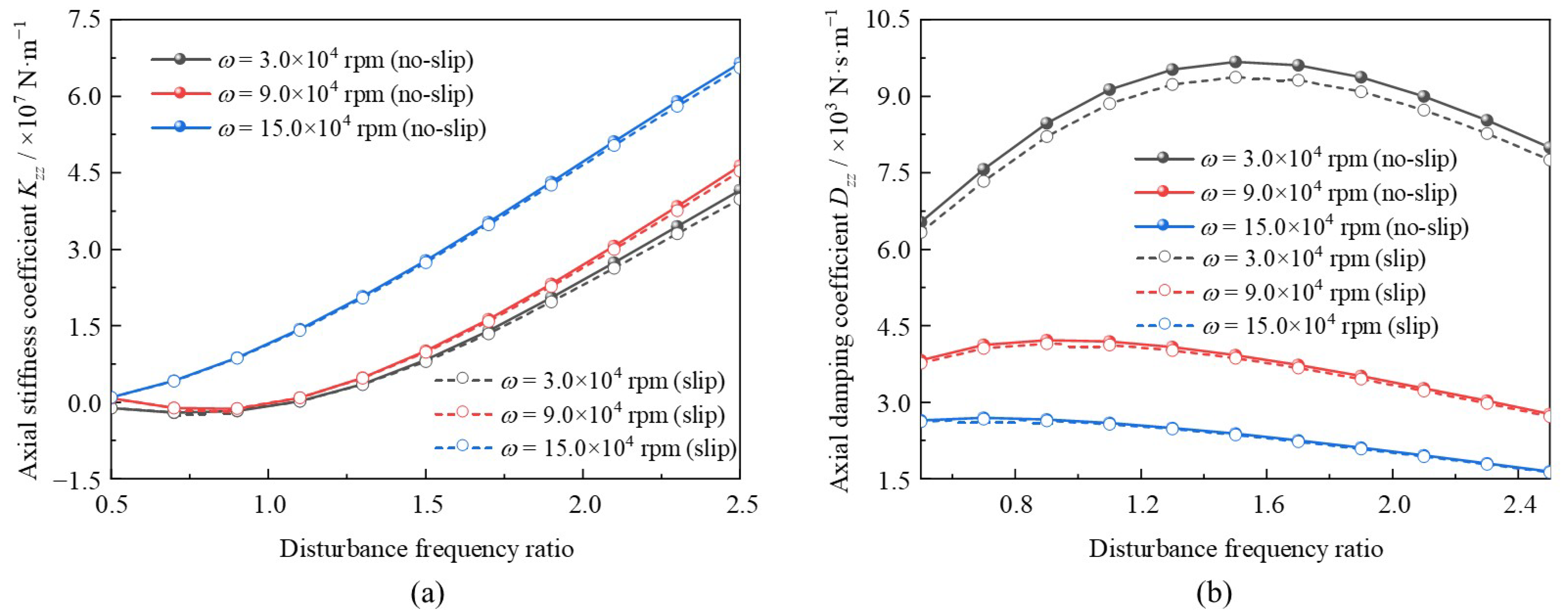
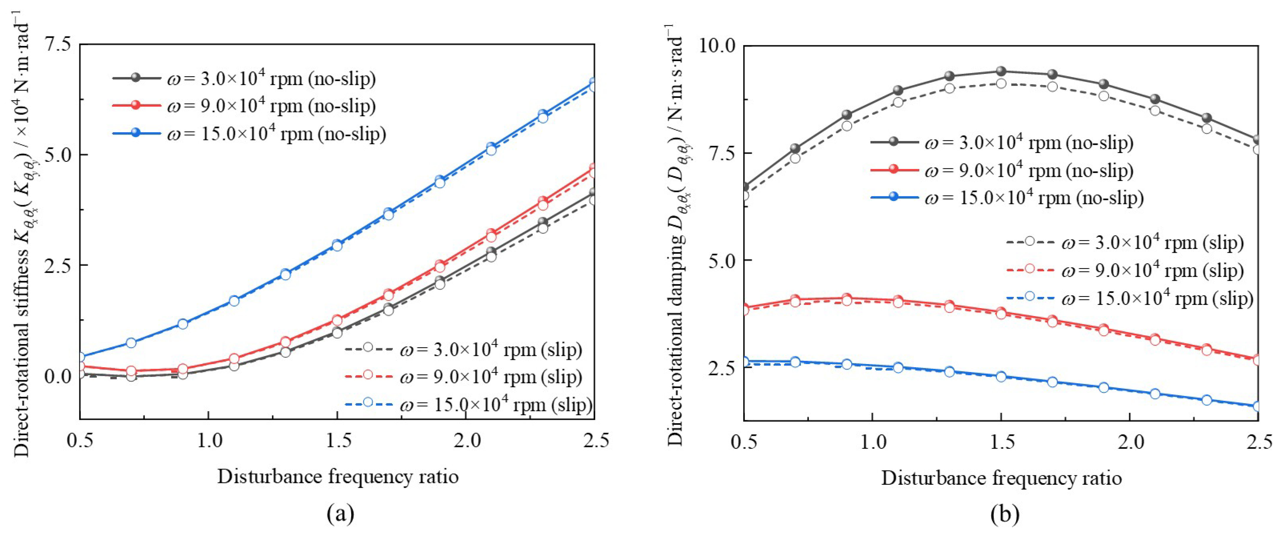
−6 m. The relevant variation laws of the axial, direct-rotational, and cross-rotational coefficients are depicted in
Figure 11,
Figure 12, and
Figure 13, respectively. Additionally, both the boundary slip and no-slip conditions were considered in the analysis.
Seen from
Figure 11, as the disturbance frequency ratio rises from
γ = 0.5 to
γ = 2.5, the axial stiffness and damping coefficients increase and decrease overall, respectively. The variation trend of the axial stiffness coefficient with respect to the disturbance frequency ratio is similar to that of the GFTB in the literature [
15]. However, at lower bearing speed (e.g.,
ω = 3.0 × 10
4 rpm), the axial damping coefficient first increases slightly and then decreases. This phenomenon can be explained as follows: at a higher disturbance frequency ratio, the rate of compression and expansion of the lubrication film accelerates, which enhances the stiffness of the lubricating film but reduces its damping performance. At lower bearing speed, such as
ω = 3.0 × 10
4 rpm, the damping coefficient of the lubricating film is relatively high; instead of being weakened by the increase in the disturbance frequency ratio, it may be enhanced by the increased expansion rate of lubricant. However, when the disturbance frequency ratio exceeds a critical value (e.g.,
γ = 1.4), the axial damping coefficient decreases, consistent with the trend observed at higher bearing speeds. When considering the slip effect, the axial damping coefficient and axial stiffness coefficient can be reduced by up to −4.09% and −3.03%, respectively, at
ω = 3.0 × 10
4 rpm. For the condition of
ω = 15.0 × 10
4 rpm, these maximum reductions are −1.45% and −0.98%, respectively. The underlying reason for this phenomenon can be attributed to the relationship between bearing speed and the slip effect, which is further discussed in
Section 2.3.
Seen from
Figure 12a, the variation in the direct-rotational stiffness coefficients with respect to the disturbance frequency ratio is identical to that of the axial stiffness coefficients. In contrast, as depicted in
Figure 13a, the cross-rotational damping coefficients decrease overall as the disturbance frequency ratio increases. Meanwhile, when the disturbance frequency ratio exceeds approximately
γ = 1.6, the direct-rotational stiffness coefficients at
ω = 15.0 × 10
4 rpm are larger, whereas the cross-rotational stiffness coefficients are smaller. This phenomenon indicates that a relatively higher bearing speed may contribute to the operational stability of MLTBFs. Additionally, the direct-rotational and cross-rotational stiffness are affected by the slip effect to different degrees. For bearing speed
ω = 3.0 × 10
4 rpm, the maximum deviation of direct-rotational stiffness coefficient (due to the slip effect) can reach −4.16%, whereas that of the cross-rotational stiffness coefficient is approximately −2.52%.
As illustrated in
Figure 12b and
Figure 13b, the variation tendencies of direct-rotational damping coefficients are similar to those of the axial damping coefficients; specifically, when the disturbance frequency ratio exceeds
γ = 1.5, the damping coefficients decrease significantly. When considering the slip effect, the direct-rotational damping coefficient can be reduced by up to −3.04% at
ω = 3.0 × 10
4 rpm, and −0.98% at
ω = 15.0 × 10
4 rpm, respectively. Additionally, due to the relatively low values, the cross-rotational stiffness coefficients may exert less influence on the operational performance of MLFTBs. It can also be inferred that the disturbance frequency has a crucial effect on the MLFTBs dynamic characteristics.
3.3. Bearing Speed
Herein, the effects of bearing speed on the dynamic characteristics are explored. As it increases from
ω = 1.5 × 10
4 rpm to
ω = 19.5 × 10
4 rpm, three typical clearance conditions are selected:
hg0 = 8.0 × 10
−6 m,
hg0 = 12.0 × 10
−6 m, and
hg0 = 16.0 × 10
−6 m. The other key parameters are kept consistent: foil number
N = 12 and disturbance frequency ratio
γ = 1.0. The variation laws of the axial, direct-rotational, and cross-rotational coefficients are depicted in
Figure 14,
Figure 15, and
Figure 16, respectively. Additionally, a comparison is conducted between the boundary slip and no-slip conditions.
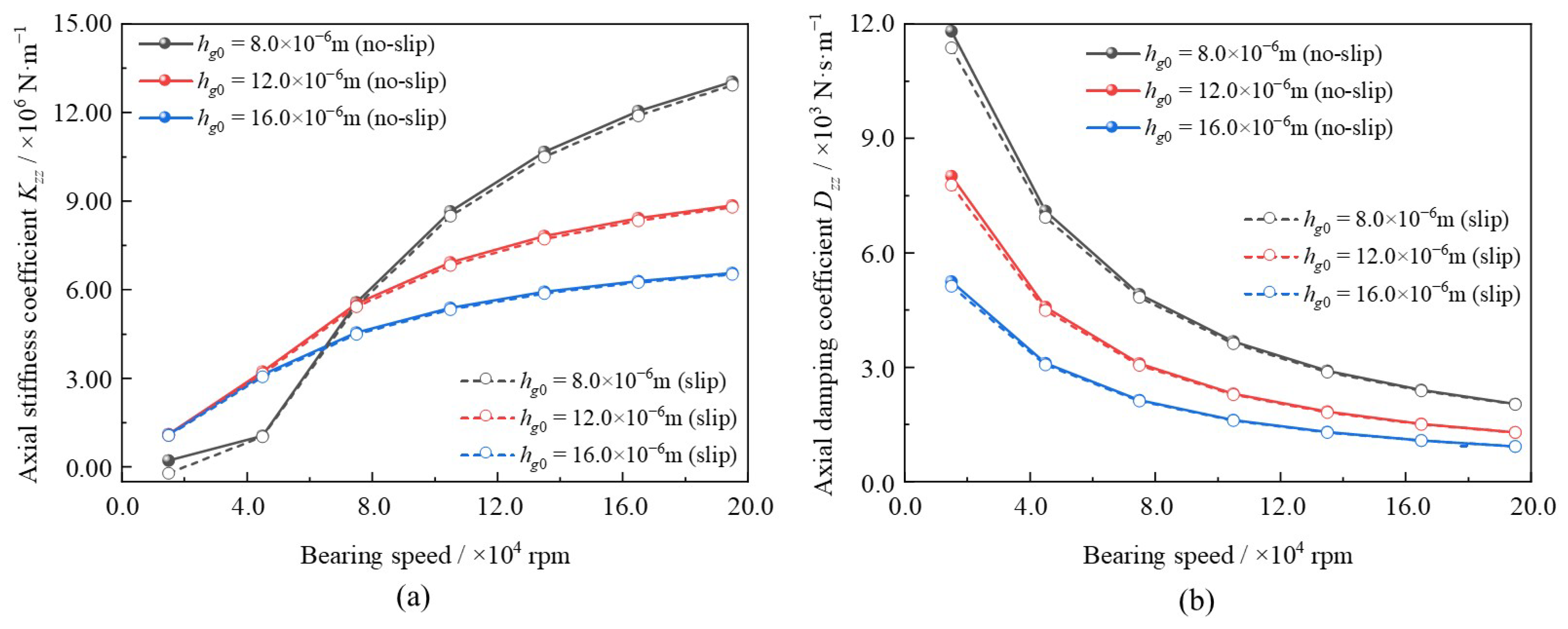
Seen from
Figure 14, when bearing speed increases from
ω = 1.5 × 10
4 rpm to
ω = 19.5 × 10
4 rpm, the axial stiffness coefficients increase nonlinearly, whereas the axial damping coefficients decrease. At high bearing speed, these variation trends are consistent with those of the GFTBs reported in the literature [
23]. This phenomenon can be caused by the fact that higher bearing speeds lead to greater lubrication pressure, which becomes more sensitive to changes in the axial position of the thrust disc. Consequently, the axial damping coefficient will be enlarged subsequently. Furthermore, at a smaller clearance (e.g.,
hg0 = 8.0 × 10
−6 m), the axial stiffness and damping coefficient exhibit more significant changes. This is attributed to the stronger aerodynamic effect of the lubrication pressure in narrower clearances.
Additionally, in comparison to the no-slip conditions, the axial coefficients under boundary slip conditions are lower, and these differences are more pronounced at smaller bearing speeds. This is because the slip effect reduces the velocity of the lubricating gas, and consequently decreases the lubrication pressure and thus lowers the axial coefficients. Moreover, the proportion of boundary slip velocity is higher at lower bearing speeds, leading to a more obvious impact of the slip effect. This variation law is consistent with that of the static characteristics of MLFTBs. For hg0 = 8.0 × 10⁻⁶ m, the maximum deviation of the axial stiffness coefficient is approximately −4.93% at ω = 1.5 × 10⁴ rpm, while the minimum deviation is approximately −0.92% at ω = 19.5 × 10⁴ rpm. Meanwhile, the deviations of the axial damping coefficient under the same clearance are approximately −4.92% at ω = 1.5 × 10⁴ rpm and −0.89% at ω = 19.5 × 10⁴ rpm.
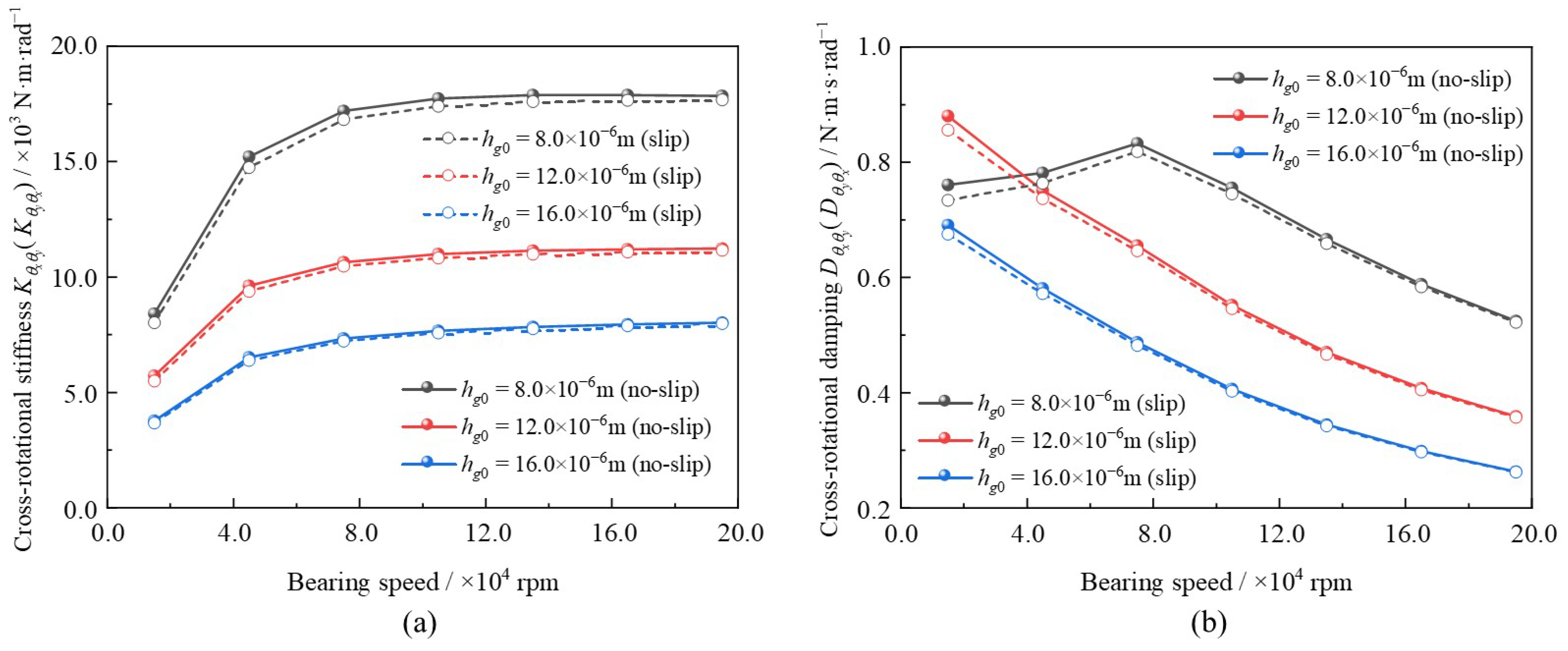
The variations in direct-rotational and cross-rotational stiffness and damping coefficients with different bearing speeds are shown in
Figure 15 and
Figure 16, respectively. As illustrated in
Figure 15a and
Figure 16a, similar to the variation pattern of the axial stiffness coefficient, both the direct-rotational and cross-rotational stiffness coefficients increase nonlinearly overall as the bearing speed increases. The reason for this phenomenon can be attributed to the fact that higher bearing speeds enhance the stiffness of the lubricating film in narrow clearances, thereby increasing the stiffness coefficients in different directions. When considering the slip effect, the direct-rotational and cross-rotational stiffness coefficients decrease, with more pronounced influences observed at lower bearing speeds and smaller clearances. The underlying reasons for this phenomenon are consistent with those explaining the variation in the axial stiffness coefficient. For
hg0 = 8.0 × 10
−6 m, the maximum deviation of the direct-rotational stiffness coefficient is approximately −5.02% at
ω = 1.5 × 10
4 rpm, whereas the minimum deviation is about −1.05% at
ω = 19.5 × 10
4 rpm.
Meanwhile, seen from
Figure 15b and
Figure 16b, the direct-rotational and cross-rotational damping coefficients generally decrease as bearing speed increases. Furthermore, under the same conditions, the values of cross-rotational damping coefficients are one order of magnitude smaller than those of the direct-rotational damping coefficients. This indicates that the dynamic characteristics of MLFTBs are less influenced by the cross-rotational damping coefficients. Additionally, when considering the slip effect, both the direct-rotational and cross-rotational damping coefficients decrease, though their absolute deviations are smaller than those of the direct-rotational and cross-rotational stiffness coefficients. For example, at
hg0 = 8.0 × 10
−6 m and
ω = 1.5 × 10
4 rpm, the maximum deviation of the direct-rotational damping coefficients is approximately −3.68%, whereas that of the cross-rotational damping coefficients is approximately −3.55%.
3.4. Foil Number
At present, the influences of the foil number on dynamic coefficients are explored. As presented in
Figure 17,
Figure 18 and
Figure 19, the foil number is set to range from
N = 6 to
N = 18, while the disturbance frequency ratios vary from
γ = 0.5 to
γ = 1.5. Other parameters are kept identical: bearing speeds
ω = 9.0 × 10
4 rpm and clearance
hg0 = 8.0 × 10
−6 m.
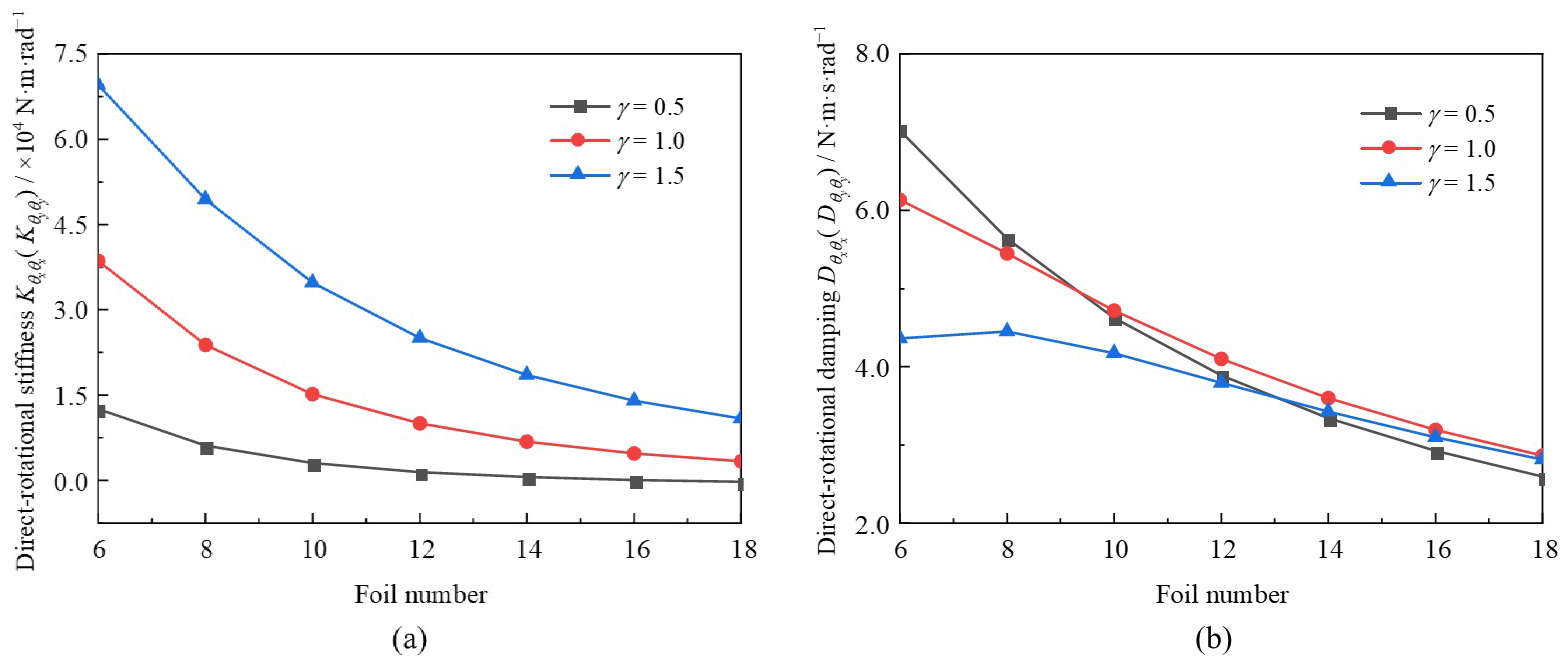
As illustrated in
Figure 17a and
Figure 18a, within the research scope of this study, the axial and direct-rotational stiffness coefficients decrease overall with an increase in the foil number, and the amplitude of this decrease gradually approaches a stable value. For a given foil number, the axial and direct-rotational stiffness coefficients increase when the perturbation frequency ratio is larger. This phenomenon can be attributed to the fact that the hydrodynamic effect shrinks with a rise in the foil number and intensifies with an increase in the disturbance frequency ratio [
25]. In comparison with
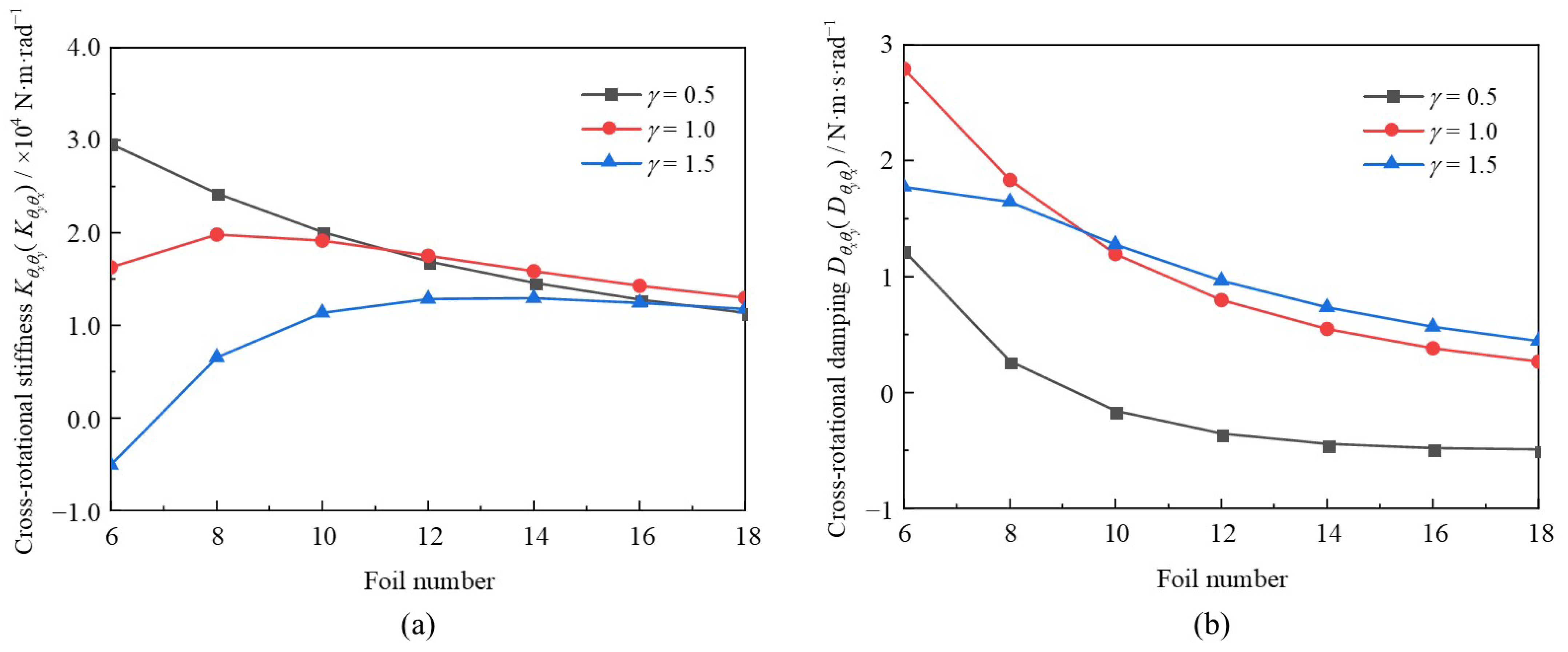
Figure 19a, the values of the direct-rotational stiffness coefficients are larger than those of the cross-rotational stiffness coefficients. Additionally, when the foil number is larger, the cross-rotational stiffness coefficients first increase and then decrease. For a small foil number, as the disturbance frequency ratio increases, the cross-rotational stiffness coefficient also first increases and then decreases. This can be explained by the slight enhancement of the hydrodynamic effect under the conditions of a small foil number and a small disturbance frequency ratio [
25].
The variations in the axial and direct-rotational damping coefficients are illustrated in
Figure 17b and
Figure 18b. As depicted in these figures, both the axial and direct-rotational damping coefficients decrease rapidly with an increase in the foil number. For a given small foil number, the axial and direct-rotational damping coefficients are lower when the disturbance frequency ratio is larger. This phenomenon can be attributed to decreased stability of the rotor-bearing system, as described in Formula (32).
Additionally, to better explore the effects of the foil number, the damping coefficients under various foil numbers and different disturbance frequency ratios are depicted in
Figure 18b and
Figure 19b. By comparing
Figure 18b and
Figure 19b, it can be observed that the direct-rotational damping coefficients are larger than those of the cross-rotational ones. This finding is consistent with the results for the stiffness coefficients illustrated in
Figure 18a and
Figure 19a. As seen in
Figure 19b, when the foil number exceeds 10, the cross-rotational damping coefficient decreases with a rise in the disturbance frequency ratio.
3.5. Comprehensive Structural Damping
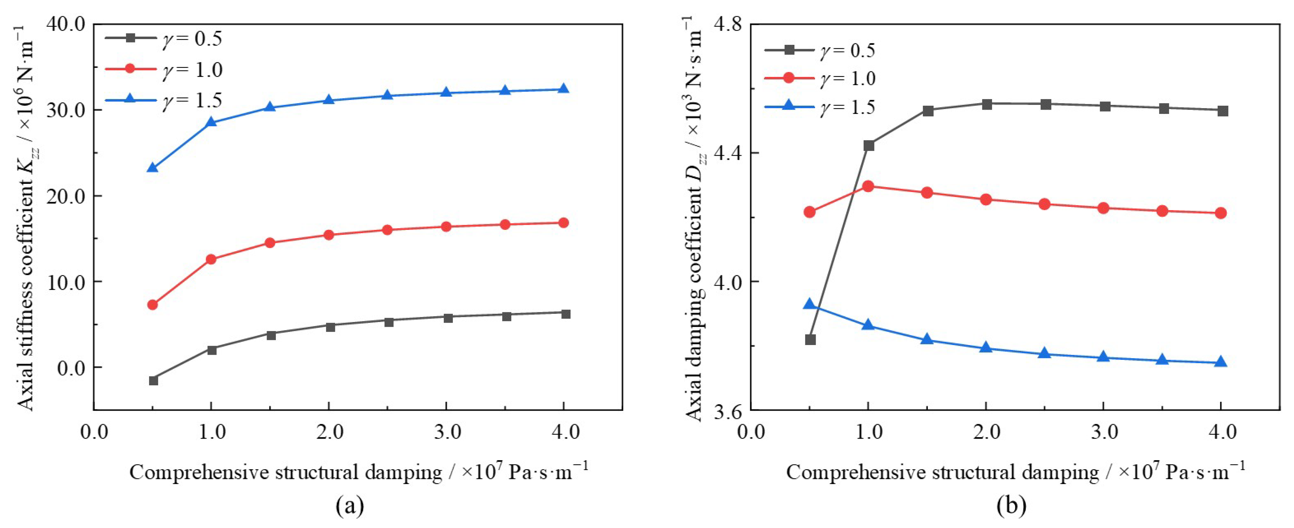
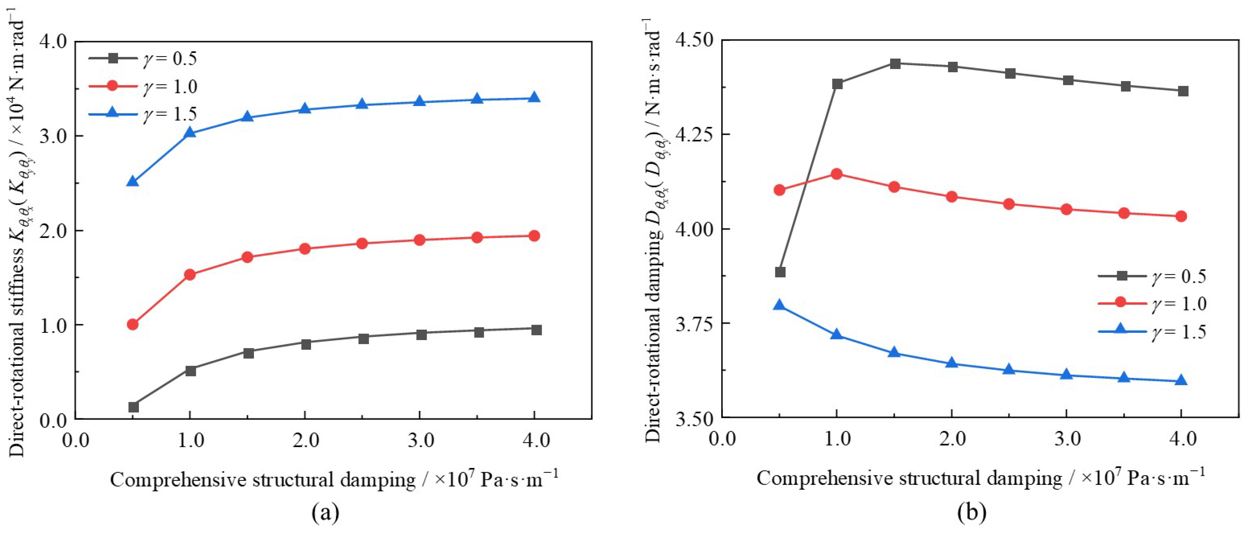
In this section, the effects of the comprehensive structural damping of the foils are discussed. The comprehensive structural damping was increased from
Db = 5.0 × 10
6 Pa·s·m
−1 to
Db = 40.0 × 10
6 Pa·s·m
−1 under different disturbance frequency ratios (
γ = 0.5 to
γ = 1.5). Other key parameters remained identical: bearing speed
ω = 9.0 × 10
4 rpm, foil number
N = 12, and clearance
hg0 = 8.0 × 10
−6 m. The relevant change rules of the axial, direct-rotational, and cross-rotational coefficients are depicted in
Figure 20,
Figure 21, and
Figure 22, respectively.
As seen in
Figure 20a and
Figure 21a, both the axial and direct-rotational stiffness coefficients increase with the rise in comprehensive structural damping, and the magnitude of this increase gradually decreases. Additionally, as shown in
Figure 20b and
Figure 21b, with the increase in comprehensive structural damping, both the axial and direct-rotational damping coefficients first increase and then decrease overall. For a given comprehensive structural damping larger than 1.0 × 10
7 Pa·s·m
−1, the axial and direct-rotational stiffness coefficients decrease when the disturbance frequency ratio is larger. It can be inferred that as the disturbance frequency ratio increases, the comprehensive structural damping required to achieve the optimal axial and direct-rotational damping coefficients will decrease.
Additionally, as seen in
Figure 22a, with an increase in comprehensive structural damping, the cross-rotational stiffness coefficient decreases slightly when the disturbance frequency ratio exceeds 1.0. In contrast, at a small perturbation frequency ratio of 0.5, the cross-rotational stiffness first increases and then stabilizes. As depicted in
Figure 22b, among the damping coefficients, the cross-rotational damping coefficients are smaller than the axial and direct-rotational ones. Furthermore, the cross-rotational damping coefficients increase overall with the rise in comprehensive structural damping. Due to the relatively low values of the cross-rotational stiffness coefficients, they may exert less influence on the operational performance of MLFTBs.
The computed bearing stiffness and damping coefficients can be the most critical and direct input parameters for predicting system-level rotor-dynamic phenomena, such as critical speeds and stability thresholds.
4. Conclusions
This study proposes a modified model for analyzing the dynamic characteristics of MLFTBs, which achieves both high computational efficiency and accuracy. To establish this model, key components are integrated: the thick plate element, a comprehensive structural damping model, and a small perturbation method. Additionally, a revised compressible Reynolds equation—coupled with the boundary slip model—is linearized and derived using the Newton–Raphson method. Leveraging this model, the variation laws of MLFTB dynamic characteristics with respect to geometric and operational parameters were systematically predicted and analyzed. The main conclusions are as follows:
- (1)
The proposed simulation model advances the analysis of MLFTB dynamic characteristics. It enables efficient and accurate numerical prediction of how parameters influence these characteristics, addressing the need for reliable tools in MLFTB performance evaluation and design optimization.
- (2)
Results indicate that when the boundary slip effect is considered, the maximum deviations of the axial and direct-rotational stiffness coefficients reach −4.93% and −5.02%, respectively. This effect is particularly significant under operating conditions of tiny clearance and low bearing speed, making it essential to incorporate the boundary slip effect into MLFTB dynamic analysis for such scenarios.
- (3)
The direct-rotational stiffness coefficient increases with a larger disturbance frequency ratio, whereas the cross-rotational stiffness coefficient exhibits a distinct turning point in its variation trend. Under the boundary slip effect, the maximum deviations of the direct and cross-rotational stiffness coefficients are up to −4.16% and −2.52%, respectively.
- (4)
An increase in comprehensive structural damping induces subtle changes in MLFTB dynamic coefficients: the axial and direct-rotational stiffness show a slight increase, while the axial and direct-rotational damping coefficients exhibit a slight decrease. Importantly, MLFTBs maintain good operational stability across the range of comprehensive structural damping values investigated.
In brief, the results focus on identifying and quantifying the parameters that influence MLFTB dynamic characteristics, laying a theoretical foundation for further research. Further investigations could explore the thermo–elasto–aerodynamic effect, which would deepen insights into MLFTB behavior and contribute to optimizing their operational performance. Additionally, a logical and critical next step, based on the fundamental parameters obtained in this study, is the construction of a rotor-bearing test rig. This rig would enable experimental validation of MLFTB dynamic performance within a real rotor system, with specific emphasis on measuring critical speeds and stability limits, thereby bridging the gap between theoretical prediction and industrial application.


