Abstract
Enhancing the high-temperature tribological performance of protective claddings is crucial for demanding industrial applications. This study focuses on developing hexagonal boron nitride (hBN)-reinforced Ni-based composite claddings to improve wear resistance over a wide temperature range. Ni/WC/CeO2 cladding layers with varying hBN contents (0.25 wt% and 0.75 wt%) were fabricated on 45 steel substrates via vacuum cladding. Their microstructure, mechanical properties, and tribological behavior under thermal cycling (25–600 °C) were systematically evaluated. Results reveal that the in situ formation of a hard Cr2B phase, coupled with hBN addition, was key to achieving optimal overall properties. The composite with 0.25 wt% hBN (NWB25) demonstrated optimal overall properties, featuring the lowest porosity (0.1813%) and the highest H/E ratio (0.0405), leading to the best overall tribological performance. A distinct transition from mild to severe wear was observed during the 300 °C-2 stage, resulting from the fracture of a high-temperature tribo-oxidative layer. An hBN content of 0.25 wt% is identified as optimal for balancing solid lubrication and matrix cohesion, thereby achieving superior thermal cycling wear resistance. Higher hBN concentrations promote grain coarsening and increased porosity, which degrade performance.
1. Introduction
The development of protective cladding layers resistant to thermal cycling wear is crucial for advancing technologies in aerospace, power generation, and heavy machinery. Nickel-based composites, such as those reinforced with tungsten carbide (WC) [1,2,3,4,5], are widely used in these applications due to their ability to combine the toughness of the matrix with the hardness of reinforcing phases. However, a significant limitation of these systems is their frequent deterioration in tribological performance at elevated temperatures, typically manifesting as a sharp increase in the coefficient of friction and wear rate [6,7]. This degradation often stems from matrix softening, the breakdown of reinforcements, and the lack of effective interfacial lubrication, collectively leading to severe adhesive and oxidative wear. Incorporating solid lubricants to form transfer films during friction across a wide temperature range can impart self-lubricating properties, thereby significantly improving high-temperature tribological performance [8,9,10,11,12].
Commonly used high-temperature solid lubricants in metal matrix composites include CaF2 [13,14], MoS2 [15,16,17,18], and Hexagonal boron nitride (hBN) [19,20,21,22,23,24]. For instance, Jinming Zhen [25] prepared a Ni/5 wt% CaF2 composite via hot-press sintering, achieving a minimum wear rate of 7.1 × 10⁻⁵ mm3/(N·m) at 200 °C, indicating its optimal service temperature is within the medium-to-low range. In another case, the addition of 10 wt% MoS2 to a Ni alloy reduced the wear rate to 0.4 × 10⁻⁵ mm3/(N·m) at 500 °C but also decreased the microhardness by 27.76% and increased the COF to 0.41. Thus, while CaF2 and MoS2 can improve the tribological properties of Ni-based alloys, they often compromise mechanical integrity and exhibit limited effectiveness at higher temperatures.
h-BN presents a promising alternative due to its weak interlayer bonding, facilitating easy shear, and excellent thermal stability. Moreover, boron from hBN can react in situ with Cr in the Ni-based alloy to form hard Cr2B phases, enhancing alloy hardness and offsetting the potential softening effect from the lubricant, thereby achieving a “lubrication-reinforcement” synergy. Studies by Xu Huang [19], Yue Zhao [26], and Xiaolong Lu [27] have demonstrated that laser-cladded hBN-reinforced Ni-based composite coatings on substrates like 45 steel, Q235 steel, and 304 stainless steel promote the formation of self-lubricating transfer films, effectively reducing friction and wear. Nevertheless, these studies primarily evaluated tribological performance under isothermal conditions, failing to replicate the thermal cycling processes (e.g., room temperature → high temperature → room temperature) typical in real-world applications, which can induce more complex and severe degradation mechanisms [28].
This study employed vacuum cladding technology to fabricate hBN-Ni/WC/CeO2 composite cladding layers with different hBN contents (0.25 and 0.75 wt%) on 45 steel substrates. The phase composition, mechanical properties, and tribological behavior during thermal cycling between 25 and 600 °C were systematically investigated. Emphasis was placed on evaluating the tribological performance during both heating and cooling processes, revealing the mechanism and failure behavior of hBN under thermo-mechanical coupling conditions.
2. Experimental Procedures
2.1. Materials Preparation
A 45 steel plate (dimensions: 50 mm × 40 mm × 10 mm) was used as the substrate. Prior to vacuum cladding, the substrate surface was ground and polished, ultrasonically cleaned in absolute ethanol, dried, and then stored for subsequent use. The detailed parameters of the nickel-based alloy powder, WC powder, and CeO2 powder are provided in our previous study [29]. The chemical composition of the 45 steel and Ni-based alloy powders is listed in Table 1. The hBN (Hexagonal boron nitride) powder was supplied by Shanghai Buwei Applied Materials Technology Co., Ltd. (Shanghai, China) with a density of 2.25 g/cm3. In the cladding layer, the weight fractions of WC and CeO2 were kept constant at 30% and 0.5%, respectively, while the weight fractions of hBN were 0.25% and 0.75%. The detailed composition is listed in Table 1.

Table 1.
Chemical composition of the 45 steel and Ni-based alloy powders (wt%).
The poor wettability between nickel-based alloys and h-BN often leads to its inhomogeneous distribution within the matrix, consequently exerting detrimental effects on the mechanical properties of the alloy [30]. To enhance the dispersion homogeneity of h-BN, an ultrasonic dispersion process was utilized. A quantified amount of h-BN powder was added to a beaker containing anhydrous ethanol and subjected to ultrasonic treatment for 24 h using an ultrasonic cleaner. Subsequently, the pre-weighed CeO2 powder was added slowly and in batches to the resulting h-BN suspension, followed by further ultrasonic treatment for 6 h. The ultrasonic dispersion was performed using a KQ-100E ultrasonic cleaner (Kunshan Ultrasonic Instrument Co., Ltd., Kunshan, China) operating at a frequency of 80 kHz. After achieving a homogeneous dispersion, the subsequent steps were consistent with those described in our previous study [29]. Table 2 shows the sample numbers and specific compositions.
Table 2.
Sample numbers and chemical composition.
Table 2.
Sample numbers and chemical composition.
| Sample | Components (wt%) | |||
|---|---|---|---|---|
| Ni-Based Alloy | WC | CeO2 | hBN | |
| NWB25 | 69.25 | 30 | 0.5 | 0.25 |
| NWB75 | 68.75 | 30 | 0.5 | 0.75 |
2.2. Mechanical Test
Microhardness of the surface and interfacial regions of the cladding layer was measured using a W1102D37 (Sauer-Danfoss Co., Ames, IA, USA) micro-Vickers hardness tester with a load of 200 gf and a dwell time of 10 s. Nanoindentation tests were performed using a KLA G200 nanoindenter (KLA Corporation, Milpitas, CA, USA) with the continuous stiffness measurement (CSM) mode, applying a peak load of 10 mN at a loading rate of 0.5 mN/s. Each test was repeated at least three times per location to ensure data reliability.
2.3. Thermal Cycling Friction Test
This study employed an HT-1000 ball-on-disk tribometer to conduct thermal cycle friction tests. The test conditions were set as follows: a load of 10 N, a sliding speed of 0.235 m/s, and a duration of 30 min for each individual friction test. The counter body was a Si3N4 ball with a diameter of 6 mm, which was ultrasonically cleaned in anhydrous ethanol prior to testing. Five specimens were prepared for each group, and friction tests were conducted at 25 °C (25 °C-1). After the friction test at 25 °C, the friction tester was heated to 300 °C, held at this temperature for 10 min, and then the friction test was conducted (300 °C-1). Following friction tests at 25 °C and 300 °C, the temperature was raised to 600 °C and maintained for 10 min before performing the friction test (600 °C-1). After undergoing friction tests at 25 °C, 300 °C, and 600 °C, the temperature was reduced to 300 °C and maintained for 10 min before performing the friction test (300 °C-2). After friction tests at 25 °C, 300 °C, 600 °C, and 300 °C, the temperature was lowered to 25 °C, and the specimens were held at this temperature for 10 min before performing the friction test (25 °C-2). The heating rate was set at 10 °C per minute. The cooling time from 600 °C to 300 °C was 20 min, and from 300 °C to 25 °C was 30 min. To ensure the reliability of the experimental results, each composition was tested in triplicate. The three-dimensional morphology of the wear tracks were characterized using a Rtec UP-2000 white light interferometer(Rtec Instruments, San Jose, CA, USA). The two-dimensional profile of the wear track cross-section was measured using a white light interferometer, from which the cross-sectional area was determined. The circumference of the wear track was then calculated based on the radius of the friction track. Finally, the wear volume was obtained by multiplying the average cross-sectional area by the wear track circumference. The wear track surfaces inside and outside were measured using an ATR3110 Raman spectrometer (Optosky, Xiamen, Fujian Province, China). The temperature protocol and the schematic diagram of the setup for the thermal cycling friction test correspond to Figure 1a and Figure 1b, respectively.
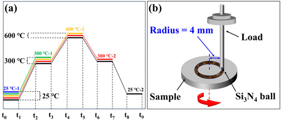
Figure 1.
(a) Schematic diagram of the temperature protocol for the thermal cycling friction test; (b) Schematic diagram of the tribological test setup.
2.4. Microstructural Characterization
The metallographic specimens were cut from the cladding samples using electrical discharge wire cutting, followed by polishing with sandpaper up to 3000 grit, and diamond spray polishing with a particle size of 0.5 μm. The porosity was quantified by statistically analyzing no less than eight SEM images after binarization processing using Image-Pro Plus 6.0 software. The threshold for segmentation was set via a combination of automated calculation and manual fine-tuning to ensure accurate pore identification. Phase analysis was performed using a D/max-2400 X-ray diffractometer (Rigaku, Tokyo, Japan). The CeO2 and h-BN samples were subjected to thermogravimetric analysis using a TGA 4000 thermal analyzer (PerkinElmer, Waltham, MA, USA) in a N2 atmosphere. The microstructure and wear tracks of the cladding layer were analyzed using a Quanta 450-FEG scanning electron microscope (FEI Company, Hillsboro, OR, USA) and its attached EDS elemental scanner (EDAX LLC, Mahwah, NJ, USA).
3. Result and Discussion
3.1. Morphology of h-BN Nanosheets
Figure 2 displays the microstructure and phase composition of the hBN powder. The TEM image in Figure 2a clearly shows the overall morphology of the hBN powder, which is characterized by typical aggregates of numerous crystalline grains. The HRTEM image (Figure 2b) further reveals an interplanar spacing of 0.332 nm, which corresponds well to the (002) plane of hBN, thus confirming its highly ordered layered crystal structure. The SAED (Selected Area Electron Diffraction) pattern (Figure 2c) shows sharp and well-defined diffraction spots, further attesting to the presence of the (002) plane and indicating the good single-crystalline nature of the selected area. The XRD pattern (Figure 2d) exhibits a strong diffraction peak at 2θ = 26.7°, which is in excellent agreement with the (002) plane of the standard card (JCPDS No. 34-0421). The presence of other characteristic peaks, such as (100), (101), (102), and (110), further confirms the high purity and well-crystallized nature of the hexagonal boron nitride sample.
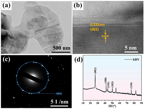
Figure 2.
(a) TEM image of hBN powder; (b) HRTEM image of hBN powder; (c) SAED pattern of hBN powder; (d) XRD pattern of hBN.
3.2. Phase Composition and Micromorphology
Figure 3a presents the XRD pattern of the hBN-Ni/WC/CeO2 cladding layers. Compared to the CeO2-Ni/WC cladding layer [31], the phase composition exhibited significant differences, with additional Cr2B and hBN phases being detected in the hBN-Ni/WC/ CeO2 cladding layer. Cr2B is an in situ formed hard intermetallic reinforcement phase. Its formation is attributed to the high-temperature reaction between Cr and B elements during the cladding process. This phase possesses high hardness (typically 1500–2000 HV) and good thermal stability, which contributes to the enhancement of the cladding layer’s resistance to plastic deformation and wear resistance through an effective second-phase strengthening mechanism, particularly under high-temperature wear conditions [32,33]. The hBN phase facilitates the formation of a lubricating tribofilm at the contact interface during sliding, effectively reducing the friction coefficient due to the easy shear between its lamellae. TGA results (Figure 3b) indicate a mass retention of 98.41% for CeO2 at 1060 °C, while hBN exhibited a significantly higher mass retention of 99.95% at the same temperature. This provides direct evidence for the thermal stability of hBN and its ability to remain largely undecomposed during the cladding process. Furthermore, the combination of hBN and the in situ formed hard Cr2B phase establishes a lubrication-reinforcement synergy, whereby the Cr2B phase primarily imparts resistance against wear and plastic deformation, and the hBN phase mitigates shear stresses during friction. Therefore, this synergy is anticipated to endow the composite cladding layer with balanced and superior tribological performance across a wide temperature range.
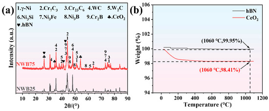
Figure 3.
(a) XRD pattern of hBN- Ni/WC/CeO2 cladding layer; (b) TGA of hBN and CeO2.
Figure 4a,b present the microstructure of the NWB25 and NWB75 cladding layers, respectively. Low-magnification SEM images (Figure 4a,b) indicate that both cladding layers are overall continuous and dense, free from macroscopic defects such as cracks. Higher-magnification images (Figure 4(a1,b1)) reveal that the dark gray Ni-based matrix is embedded with a large number of irregularly shaped, bright white reinforcement phases. These bright white phases exhibit highly irregular geometries with distinct boundaries and sharp edges. Their size distribution is non-uniform, with some particles aggregating into larger clusters while others are individually embedded within the matrix. The particle surfaces are not smooth, exhibiting slight undulations and surface roughness. Additionally, blocky phases in a light gray contrast are also observed. Figure 4c presents the quantitative analysis of the effect of hBN content on the microstructure of the hBN-Ni/WC/CeO2 cladding layers. A comparison between NWB25 and NWB75 reveals significant differences in their grain size and porosity. The average grain size increased from 28.14 nm for NWB25 to 38.35 nm for NWB75, suggesting that a higher hBN content promotes grain coarsening. Similarly, the porosity increased from 0.1813% for NWB25 to 0.2351% for NWB75. Compared to the 0.5 wt% CeO2-Ni/WC cladding layer (average grain size: 12.06 nm; porosity: 0.0673%), these results indicate that the incorporation of hBN may be detrimental to achieving greater densification and grain refinement [19,23,34].
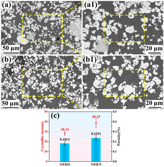
Figure 4.
(a) SEM morphology of NWB25; (a1) Figure 4a enlarged morphology of the rectangular box; (b) SEM morphology of NWB75; (b1) Figure 4b enlarged morphology of the rectangular box; (c) The porosity and average grain size of the hBN-Ni/WC/CeO2 cladding layer. In Figure 4(a1) and Figure 4(b1), the yellow dotted boxes indicate the morphological features presented in Figure 5a and Figure 5b, respectively.
To systematically analyze the microscopic phase composition, Figure 5a,b present the SEM morphology and the corresponding EDS elemental maps for the NWB25 and NWB75 cladding layers, respectively. The corresponding EDS point analysis data are listed in Table 3. Combined with EDS point analysis (Table 3) and XRD results, the dark gray continuous matrix (Point 1), primarily containing Ni, Cr, and Fe, was identified as the γ-Ni solid solution and Ni3Fe. The bulk light gray phase (Point 2) is rich in Cr and C, with an atomic ratio consistent with the theoretical values for Cr7C3 and Cr23C6 carbides. Point 3 exhibits enrichment of Fe, Ni, and Si. The atomic percentages of Ni and Si (34.92% and 11.84%, respectively) are close to the 3:1 stoichiometric ratio of Ni3Si, identifying this phase as the Ni3Si intermetallic compound. The white particulate phases (Points 4 and 5) are primarily composed of W and C, and their composition is similar across different measurement points. Combined with the XRD diffraction peaks, these phases are confirmed to be a mixture of WC and W2C. The EDS maps (areas marked by red circles in Figure 5a,b, corresponding to the black dotted phases) show simultaneous enrichment of B, N, and Cr elements, indicating the presence of hBN and Cr2B phases. These phases are uniformly dispersed within the cladding layer, demonstrating that the ultrasonic dispersion process achieved excellent uniformity in hBN distribution.
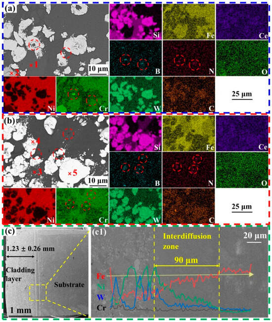
Figure 5.
(a) SEM morphology and EDS elemental distribution map within the box of Figure 4(a1); (b) SEM morphology and EDS elemental distribution maps within the box of Figure 4(b1); (c) Cross-sectional SEM morphology of NWB25; (c1) Figure 5c EDS element line scan results of the rectangular area. The red dotted circles indicate the regions of elemental enrichment at the corresponding locations in Figure 5a,b.
Table 3.
EDS point scanning results (at%) of different point in Figure 5a,b.
The interfacial bonding characteristics between the NWB25 cladding layer and the 45 steel substrate were investigated through cross-sectional microstructure observation and EDS line scanning results, as shown in Figure 6c. The composite cladding layer exhibits a uniform thickness with an average value of 1.23 ± 0.26 mm. EDS line scanning across the interface revealed clear compositional gradients of the main elements (Ni, Fe, Cr, and W) across the interface, with an interdiffusion zone width of approximately 90 μm. The formation of this diffusion layer is indicative of good metallurgical bonding between the cladding layer and the substrate. In contrast to the 0.5 wt% CeO2-Ni/WC cladding layer (fabricated using the same process parameters) reported in previous studies, which exhibited a much broader interdiffusion zone of ~210 μm [31], the introduction of hBN in the present study significantly suppressed the elemental interdiffusion at the interface. This suggests that hBN likely influences the melt pool fluidity, interfacial energy, or diffusion kinetics, thereby reducing the diffusion rates of metallic atoms and ultimately playing a key role in tailoring the interfacial microstructure and bonding properties.
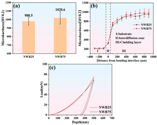
Figure 6.
(a) Surface microhardness distribution; (b) Microhardness distribution across cross-sections; (c) Nanoindentation load-depth curve.
3.3. Microhardness and Nanoindentation
Figure 6a presents the microhardness measured on the surface of the cladding layers. The microhardness of the cladding layer increases with the hBN content, indicating that a higher hBN content promoted the formation of more Cr2B hard phases, thereby enhancing the overall microhardness of the cladding layer. Figure 6b displays the microhardness profile along the cross-sectional depth (from the cladding layer, through the interdiffusion zone, to the 45 steel substrate). From the substrate to the interdiffusion zone, the hardness increases gradually. This gradual change arises from the good metallurgical bonding enabled by the ~90 μm wide interdiffusion zone, which prevents a sharp property gradient between the dissimilar materials. However, from the interfacial zone to the cladding layer itself, the hardness exhibits a sharp increase, demonstrating the significant strengthening effect provided by multiple reinforcing phases (e.g., WC, Cr2B, and W2C). A notable observation is that the hardness data for the NWB75 cladding layer shows greater scatter, with a significantly larger standard deviation (error bar) than NWB25. This is directly attributed to its higher porosity (0.2351%). The inhomogeneous distribution of pores introduces greater variability in the mechanical properties.
Figure 6c presents representative nanoindentation load–displacement curves for the hBN-Ni/WC/CeO2 cladding layers. The nanomechanical properties extracted from these curves are summarized in Table 4. The results indicate that increasing the hBN content to 0.75 wt% (NWB75) significantly enhances the elastic modulus to 318.7 GPa and the nanohardness to 12.1 GPa. This represents a substantial 15.35% increase in elastic modulus relative to NWB25 (276.3 GPa), compared to a more modest 8.04% increase in nanohardness (NWB25: 11.2 GPa). The notable discrepancy between the enhanced elastic modulus and the relatively smaller improvement in nanohardness suggests that the addition of high hBN content primarily facilitates the formation or refinement of high-modulus phases (e.g., Cr2B), rather than being highly effective in improving the overall resistance to plastic deformation.
Table 4.
Mechanical properties of NWB25 and NWB75.
3.4. Thermal Cycling Tribological Performance Analysis
3.4.1. Friction and Wear Behaviors of Cladding Layers
Figure 7 systematically compares the evolution of the friction coefficient versus time for both NWB25 and NWB75 cladding layers under thermal cycling conditions, along with the average friction coefficient for each stage. In the 25 °C-1 stage, the NWB25 cladding layer, with its lower hBN content (0.25 wt%), provided an inadequate supply of solid lubricant. This resulted in slow formation of a lubricating film at the friction interface, causing pronounced fluctuations and prolonged instability in the friction coefficient. In contrast, the NWB75 cladding layer, with its higher hBN content (0.75 wt%), possessed an enhanced and sustained lubrication capacity. It rapidly formed a stable lubricating film at the initial sliding stage, resulting in a stable friction process from the outset. In the subsequent 300 °C-1 stage, both cladding layers exhibited a low initial friction coefficient. This is primarily attributed to the accumulation of wear debris generated in the previous 25 °C-1 stage at the contact interface. Some debris acted as rolling elements, providing a third-body lubrication effect which effectively reduced frictional resistance initially. As the test progressed and the temperature rose, this debris gradually induced plowing and adhesion effects on the friction surface (e.g., through debris hardening or embedding), causing the friction coefficient to increase gradually from its initial low value. During the 600 °C-1 stage, the accumulated wear debris and the material surface experienced softening and oxidation due to the high temperature, leading to a reduction in their microhardness and a consequent weakening of the plowing effect. Simultaneously, the high temperature facilitated the formation of a tribo-oxidative layer on the surface, which reduced direct mechanical interlocking between the tribo-pair. Consequently, the friction coefficient curve in this stage was overall relatively stable, with significantly reduced amplitude of fluctuations.
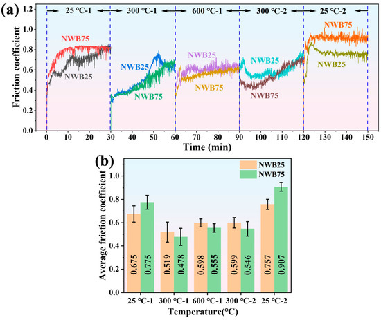
Figure 7.
(a) Friction coefficient versus time curve; (b) Average coefficient of friction.
During the 300 °C-2 test, the high initial friction coefficient indicated that the cladding layer surface still exhibited high frictional resistance at the beginning of sliding. During the 25 °C-2 test, the average friction coefficient reached the maximum value observed in the entire thermal cycle (NWB25: 0.757; NWB75: 0.907). Notably, the tribological behavior of NWB75 at this stage closely resembled that during the initial 25 °C test, primarily characterized by an overall upward shift in the friction coefficient–time curve; whereas NWB25 exhibited a markedly different evolution: after a brief running-in period, its friction coefficient did not continue to increase but rather displayed a decreasing trend. This suggests that the surface material of NWB25 may have undergone microstructural transformation or activation of lubrication mechanisms (e.g., altered lubricity of wear debris, further exposure of subsurface hBN) after the complete thermal cycle, thereby improving the tribological conditions.
Figure 8 presents the SEM morphologies and 3D morphologies of the wear tracks on the NWB25 and NWB75 cladding layers after different thermal cycling stages. SEM observations indicated that the width of the wear tracks on both cladding layers exhibited a gradual increasing trend as the thermal cycling test progressed. Notably, upon transitioning from the 600 °C-1 to the 300 °C-2 stage, the wear track width for both cladding layers underwent a sharp increase. The wear track width increased from 713 μm to 957 μm (a 34.2% increase) for NWB25, and from 773 μm to 1070 μm (a 38.4% increase) for NWB75. This suggests a significant transition in the wear mechanism of the cladding layers under the 300 °C-2 sliding conditions, evolving from mild to severe wear. Analysis of the 3D wear track morphologies revealed relatively shallow depths following the 25 °C-1, 300 °C-1, and 600 °C-1 stages. In contrast, the wear tracks became notably deeper starting from the 300 °C-2 stage.
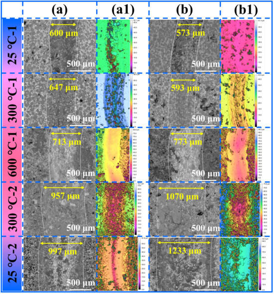
Figure 8.
(a) Wear track SEM morphology of NWB25; (a1) Three-dimensional morphology of NWB25; (b) Wear track SEM morphology of NWB75; (b1) Three-dimensional morphology of NWB75.
Figure 9a presents the cumulative wear volume of the samples during the thermal cycling test. The results show that the cumulative wear volume increased gradually as the testing progressed through the stages. Notably, upon transitioning from the 600 °C-1 to the 300 °C-2 stage, the wear volume exhibited the most pronounced increase. Figure 9b further compares the wear volume attributed to each individual test stage (defined as the difference between the cumulative wear volume at the end of a given stage and that at the end of the previous stage). Analysis revealed two distinct features: first, the incremental wear volume was the smallest at the 300 °C-1 stage. Second, the incremental wear volume was the largest at the 300 °C-2 stage. The wear volumes for NWB25 and NWB75 at this stage were 10.92-fold and 13.52-fold larger, respectively, than that at the 300 °C-1 stage.
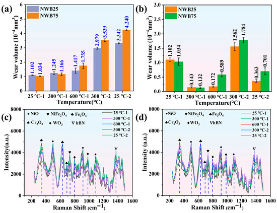
Figure 9.
(a) Wear volume in thermal cycling friction test; (b) Single-temperature-point wear volume; (c) Worn surface Raman analysis of NWB25; (d) Unworn surface Raman analysis of NWB25.
Figure 9c,d present the Raman spectra acquired from inside and outside the wear tracks on the NWB25 cladding layer, respectively. The analysis results indicate that the intensity of the characteristic Raman peaks gradually increased as the thermal cycling test proceeded. This suggests that oxidation of the wear track surface occurred continuously throughout both the heating and cooling stages of the thermal cycle. Phase analysis identified that both the inside and outside of the wear track primarily comprised NiO, NiFe2O4, Fe3O4, Cr2O3, WO3, and hBN. For a given test stage, the characteristic peaks were consistently slightly more intense inside the wear track than outside. This indicates that the formation of oxides was influenced not only by the ambient temperature, but also significantly by the additional frictional heating generated during sliding. The detection of hBN also indicates that its chemical stability was maintained during both the cladding process and the subsequent friction tests.
3.4.2. Wear Mechanism Analysis
Figure 10 presents the microscopic morphology of the worn surfaces of NWB25 and NWB75. Raman analysis after the 25 °C-1 test indicated the occurrence of tribo-oxidation on the worn surface, which was covered with smeared wear debris and a small number of spalling pits. As the test progressed to the 300 °C-1 stage, the debris on the worn surface underwent gradual granulation under the combined effects of the 300 °C temperature and cyclic stress. These particles acted as a third body. While most particles served to lubricate the tribo-pair, a small fraction caused plowing grooves on the worn surface (300 °C-1, b1). This particle lubrication effect contributed to a significant reduction in the wear volume during this stage. At the 600 °C-1 stage, the debris underwent further oxidation and sintering, forming a continuous yet loose layer. Some areas exhibited a mixture of compacted debris and spalling pits. When the temperature cycled back to 300 °C-2, the loose debris layer formed during the 600 °C-1 stage readily spalled off under the pressure from the Si3N4 counter ball at the beginning of sliding, leading to a significant increase in the wear volume for this stage. After this stage, the remaining debris was compacted under the pressure of the counter ball to form a dense tribo-oxidative layer coating the worn surface.
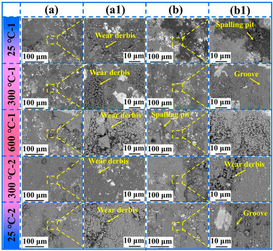
Figure 10.
(a) SEM morphologies of worn surface on NWB25; (a1) Yellow box area enlarged morphology of (a); (b) SEM morphologies of worn surface on NWB75; (b1) Yellow box area enlarged morphology of (b).
Analysis of the wear track morphology from the 25 °C-2 test revealed that the cladding layer surface exhibited characteristic features of abrasive wear, such as plowing grooves. The dense tribo-oxidative layer formed during the 300 °C-2 stage, which coated the surface, resulted in a relatively small wear volume loss during the subsequent 25 °C-2 stage. Low-magnification images revealed a non-uniform distribution of abundant debris across the wear track surface and its edges, with localized debris accumulation. This indicates a material removal mechanism dominated by brittle spalling and plastic tearing. High-magnification images further revealed prominent spalling pits and plowing grooves parallel to the sliding direction. The spalling pits with sharp edges suggest material fracture due to subsurface crack propagation, while the continuous plowing grooves reflect plastic deformation induced by hard abrasive particles or surface asperities. The debris morphology, consisting primarily of flakes and blocks, correlates with the spalling pit morphology. This indicates that during the 25 °C-2 stage, the material experienced a synergistic wear mechanism involving brittle spalling induced by fatigue accumulation and abrasive wear.
Figure 11 systematically characterizes the elemental distribution on the wear track surface of the NWB25 cladding layer throughout the thermal cycling process using EDS elemental mapping. The EDS micro-area analysis data are presented in Table 5. In the 25 °C-1 stage (Figure 11a), EDS mapping of the debris region revealed a high oxygen atomic percentage of 30.25 at%, which, combined with the characteristic peaks of metal oxides (e.g., NiO, NiFe2O4, Fe3O4, Cr2O3, WO3) identified by Raman spectroscopy at this stage, confirms that significant oxidative wear had already occurred on the material surface during the initial low-temperature sliding stage. When the temperature increased to 300 °C-1 (Figure 11b), the oxygen content within the debris increased further, indicating that the heating process significantly accelerated the surface oxidation reaction. In the 600 °C-1 stage (Figure 11c), the wear track morphology changed significantly: under the combined effects of high temperature and sustained mechanical shear, the debris agglomerated, forming a unique flocculent structure. Simultaneously, deep and continuous plowing grooves appeared on the track surface, revealing a synergistic mechanism between oxidative wear and abrasive wear under high-temperature conditions, which collectively dominated the material removal process in this stage. These findings demonstrate that the varying temperature field during thermal cycling is a key factor governing the surface oxidation behavior, the evolution of debris morphology, and the transition of wear mechanisms.
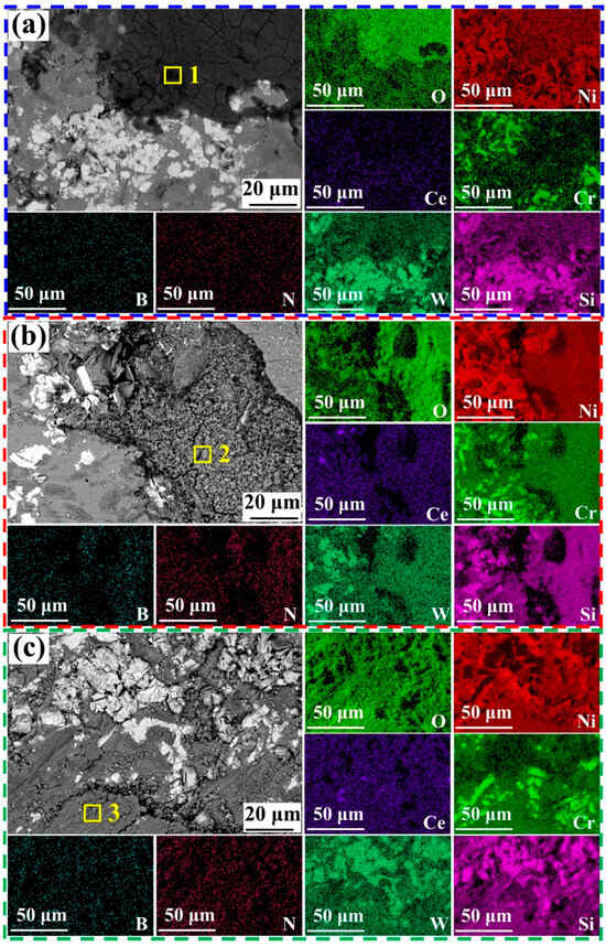
Figure 11.
SEM morphology and EDS elemental mapping of the worn surface of NWB25: (a) 25 °C-1; (b) 300 °C-1; (c) 600 °C-1. The elemental scanning results of the corresponding regions 1–3 are shown in Table 5.
Figure 12a presents the worn surface morphology following the 300 °C-2 friction test. Integrated analysis of the friction coefficient, wear track width, and wear volume data indicates this stage marks the critical transition point where the wear mechanism shifts from mild to severe wear. Morphological observation reveals that the debris transformed from the flocculent structures typical of the 600 °C-1 stage into finer particulate matter. During cooling from 600 °C to 300 °C post-stage, residual heat and ambient atmosphere promoted continued surface oxidation, forming a metal oxide layer on the wear track. During subsequent sliding at 300 °C-2, alternating stresses fractured this oxide layer, comminuting it into fine debris particles. Figure 12b presents the wear track morphology following the 25 °C-2 stage. Debris accumulation characteristics resemble those of the 25 °C-1 stage. Surface cracks initiated under alternating loads, with crack propagation ultimately causing debris to spall from the substrate into the tribo-interface.
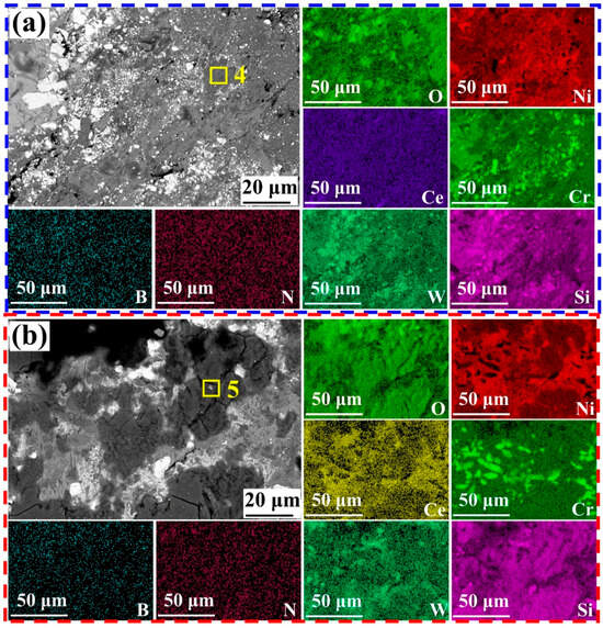
Figure 12.
SEM morphology and EDS elemental mapping of the worn surface of NWB25: (a) 300 °C-2; (b) 25 °C-2. The elemental scanning results of the corresponding regions 4 and 5 are shown in Table 5.
Figure 13 shows the cross-sectional SEM morphology and the corresponding EDS elemental mapping of the wear track from the NWB25 sample after the complete thermal cycling test. The thickness of the tribo-oxidation layer is marked on the cross-sectional SEM micrograph. The thickness of the tribo-oxidation layer on the wear scar surface was found to increase gradually (from 20.15 to 36.11 μm) as the thermal cycling test progressed. EDS elemental mapping of the wear track cross-section during the 600 °C-1 stage revealed an inhomogeneous distribution of B and N, with the presence of aggregates (Figure 13c, B and N elemental maps, indicated by red arrows). This inhomogeneity is attributed to the softening of the nickel-based matrix at 600 °C, induced by both frictional and ambient heating, which enveloped the hBN and physically hindered the formation of a continuous and effective lubricating film at the friction interface. In contrast, B and N were enriched and uniformly distributed on the wear surface in the other thermal cycling stages, indicating that hBN maintained good spreading and lubrication capabilities during the other thermal cycling stages.
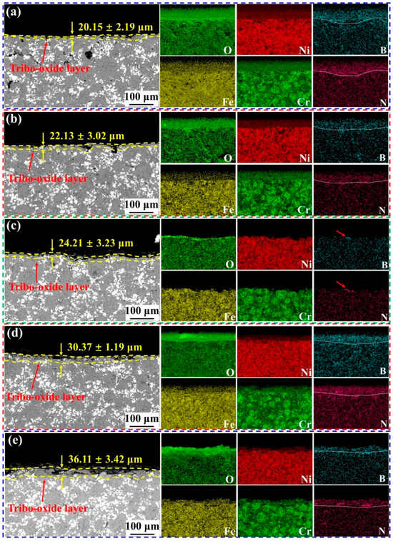
Figure 13.
Cross-sectional SEM morphology and EDS elemental mapping of the wear track on NWB25: (a) 25 °C-1; (b) 300 °C-1; (c) 600 °C-1; (d) 300 °C-2; (e) 25 °C-2.
Figure 14 systematically analyzes the evolutionary behavior of debris in hBN-Ni/WC/CeO2 cladding layers during different thermal cycling stages through microscopic morphology observation and particle size distribution statistics. In the 25 °C-1 stage, the debris exhibited a mixed morphology of irregular blocks and flakes, with a broad particle size distribution. The D50 values for NWB25 and NWB75 were 3.238 μm and 2.634 μm, respectively, and the D90 values were 9.302 μm and 7.758 μm, respectively. This indicates a dispersed debris size distribution at this stage, reflecting that material removal during the initial friction was primarily governed by brittle spalling and mild abrasive wear mechanisms. When the temperature increased to 300 °C-1, the mean particle size of the debris decreased to 3.412 μm for NWB25 and 2.793 μm for NWB75, suggesting that elevated temperature promoted mechanical fragmentation and oxidative refinement of the debris.
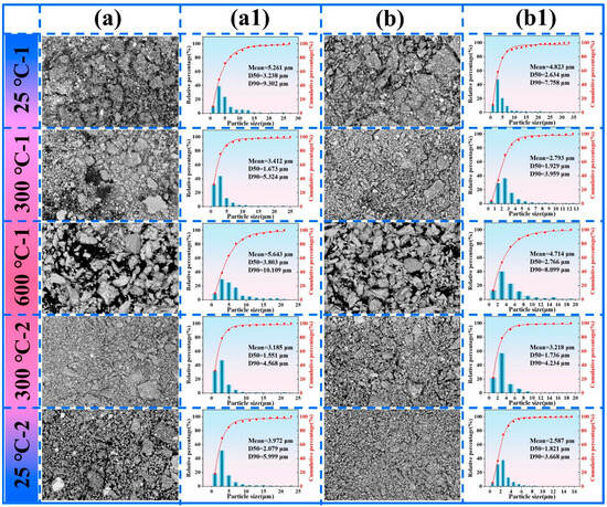
Figure 14.
(a) SEM Morphology of NWB25 wear debris; (a1) Particle size distribution of NWB25 wear debris; (b) SEM Morphology of NWB75 wear debris; (b1) Particle size distribution of NWB75 wear debris.
In the 600 °C-1 stage, the debris underwent significant spheroidization and agglomeration, with the mean size increasing to 5.643 μm for NWB25 and 4.714 μm for NWB75. This size increase primarily resulted from the plastic flow, sintering effect, and surface tension-induced coalescence of debris under high temperature. At 600 °C, hBN interacted with the Ni-based matrix, forming granular debris on the wear surface, which hindered its spreading lubrication capability. This resulted in the agglomeration of hBN, as observed in the cross-sectional analysis of the wear track. When the temperature cycled to 300 °C-2, the debris size significantly decreased with a narrower distribution, consistent with the mechanism of fragmented surface oxide layer forming fine third-body abrasives that dominated the wear process. By the 25 °C-2 stage, the mean size of NWB25 debris increased to 3.972 μm, while that of NWB75 further decreased to 2.587 μm. The larger grains and higher porosity in the NWB75 cladding layer provided space for debris accommodation, enabling more effective crushing and compaction at the interface. In contrast, fatigue accumulation in NWB25 exacerbated brittle spalling, leading to debris coarsening. Comprehensive analysis indicates that the temperature during thermal cycling significantly influences debris size and morphology by regulating surface oxidation, fragmentation, and high-temperature agglomeration. The hBN content indirectly modulates the debris evolution by altering the interfacial lubrication state and material failure behavior.
3.5. Discussion
This study systematically investigated the tribological behavior of hBN-Ni/WC/CeO2 composite cladding layers during thermal cycling, revealing the intrinsic mechanism by which a low hBN content (0.25 wt%) achieves optimal comprehensive performance. The NWB25 sample (0.25 wt% hBN) exhibited the finest grain size (28.14 nm) and the lowest porosity (0.1813%), attributed to the synergistic strengthening effect of CeO2’s grain boundary pinning and the in situ formation of fine and dense Cr2B phases facilitated by an appropriate amount of hBN. Although NWB75 (0.75 wt% hBN) showed a slightly higher microhardness (1002.6 HV0.2), its higher porosity (0.2351%) resulted in lower H/E and H3/E2 values, indicating inferior fracture toughness and resistance to plastic deformation. The thermal cycling friction tests demonstrated that the wear behavior exhibited distinct stages: in the 300 °C-1 stage, the reduction in wear volume might be associated with the refinement of wear debris, whereas the transition from the 600 °C-1 to the 300 °C-2 stage represented a critical failure point. At this point, the oxide layer formed at high temperature spalled off due to thermal fatigue induced by thermal stress during cooling, leading to a 34.2% increase in wear scar width and a sharp rise in wear volume. The superior performance of NWB25 originates from its unique “soft-hard synergy” mechanism: the Cr2B phase provides resistance to plastic deformation, hBN offers lubrication through interlayer shear (indirectly evidenced by the reduced friction coefficient and enrichment of B/N elements), and CeO2 acts as a microstructure modifier, enhancing matrix stability by grain refinement. This study confirms that 0.25 wt% hBN optimally balances the lubrication effect and structural integrity, while a higher content (0.75 wt%) disrupts this balance due to agglomeration and increased porosity. Ultimately, the core value of thermal cycling testing is clarified to lie in revealing the failure threshold and mechanism of the coating under dynamic thermal-mechanical loads, rather than pursuing perfect performance across the entire temperature range.
4. Conclusions
The hBN-reinforced Ni/WC/CeO2 cladding layer was successfully fabricated on a 45 steel substrate using vacuum cladding technology. The microstructure, phase composition, mechanical properties, and thermal cycling tribological performance were systematically investigated. The main conclusions are as follows:
- (1)
- The in situ formed Cr2B strengthening phase and hBN lubricating phase were identified in the hBN-Ni/WC/CeO2 cladding layer. They exhibit a mechanism of synergistic hardening and lubrication: the Cr2B phase enhances the resistance to plastic deformation, while the hBN phase reduces the friction coefficient via interlamellar shear.
- (2)
- NWB25 (0.25 wt% hBN) exhibits the optimal structural integrity, possessing the smallest average grain size (28.14 nm) and the lowest porosity (0.1813%) among all samples. The microhardness reaches 980.5 HV0.2, and nanoindentation results show the highest H/E (0.0405) and H3/E2 (0.0184) ratios, indicating that the low hBN content significantly enhances the resistance to plastic deformation and fracture toughness by suppressing grain coarsening and pore formation.
- (3)
- At the 600 °C-1 stage, the nickel-based matrix underwent significant thermal softening, which led to the encapsulation of hBN particles. This encapsulation physically hindered the formation of a continuous and effective lubricating film at the friction interface. In contrast, the homogeneous enrichment of B and N elements on the wear surface observed in other thermal cycling stages indicates that hBN maintained good spreading behavior and effective lubricating film-forming capability during those stages.
- (4)
- The stage from 600 °C-1 to 300 °C-2 represents a turning point in the wear mechanism: the wear track width of NWB25 increases sharply by 34.2%, and the wear volume increases significantly, indicating a transition from mild abrasive wear to severe spalling. Raman spectroscopy and cross-sectional EDS analysis reveal that the tribo-oxidation layer contains NiO, NiFe2O4, Fe3O4, Cr2O3, WO3, and hBN. The enrichment of B and N elements confirms the dynamic evolution of the high-temperature lubricating film.
Author Contributions
Conceptualization, W.S. and Y.M.; validation, investigation, data curation and writing—original draft preparation, O.L.; funding acquisition, G.Y.; project administration, W.S.; resources, Y.M.; methodology, O.L., W.S. and Y.M.; writing—review and editing, G.Y. and Y.M.; visualization, O.L. and W.S.; supervision, G.Y. and Y.M. All authors have read and agreed to the published version of the manuscript.
Funding
This research was funded by the National Natural Science Foundation of China grant number [51765035,51205178], the Open Fund of Key Laboratory of Advanced Reactor Engineering and Safety, Ministry of Education (ARES-2022-02) and the Major Science and Technology Project of Gansu Province (Grant No. 22ZD6GA008).
Data Availability Statement
The raw data supporting the conclusions of this article will be made available by the authors on request.
Conflicts of Interest
Wenming Song is employed by the Machinery Industry Shanghai Lanya Petrochemical Equipment Inspection Ltd., Lanzhou, Gansu 730070, China. The remaining authors declare that the research was conducted in the absence of any commercial or financial relationships that could be construed as a potential conflict of interest.
References
- Zhou, S.; Huang, Y.; Zeng, X.; Hu, Q. Microstructure characteristics of Ni-based WC composite coatings by laser induction hybrid rapid cladding. Mater. Sci. Eng. A 2008, 480, 564–572. [Google Scholar] [CrossRef]
- Liu, Y.; Li, Z.; Li, G.; Du, F.; Yu, M. Microstructure and Wear Resistance of Ni–WC–TiC Alloy Coating Fabricated by Laser. Lubricants 2023, 11, 170. [Google Scholar] [CrossRef]
- Zhou, S.; Lei, J.; Dai, X.; Guo, J.; Gu, Z.; Pan, H. A comparative study of the structure and wear resistance of NiCrBSi/50 wt.% WC composite coatings by laser cladding and laser induction hybrid cladding. Int. J. Refract. Met. Hard Mater. 2016, 60, 17–27. [Google Scholar] [CrossRef]
- Hou, Y.; Chen, H.; Cheng, Q.; Fan, L.; Dong, L. Effects of Y2O3 on the microstructure and wear resistance of WC/Ni composite coatings fabricated by plasma transferred arc. Mater. Express 2020, 10, 634–639. [Google Scholar] [CrossRef]
- Shu, D.; Cui, X.; Li, Z.; Sun, J.; Wang, J.; Chen, X.; Dai, S.; Si, W. Effect of the Rare Earth Oxide CeO2 on the Microstructure and Properties of the Nano-WC-Reinforced Ni-Based Composite Coating. Metals 2020, 10, 383. [Google Scholar] [CrossRef]
- Cheng, J.; Zhen, J.; Zhu, S.; Yang, J.; Ma, J.; Li, W.; Liu, W. Friction and wear behavior of Ni-based solid-lubricating composites at high temperature in a vacuum environment. Mater. Des. 2017, 122, 405–413. [Google Scholar] [CrossRef]
- Xu, Z.; Li, D.; Lu, Z.; Lv, X.; Liu, Y.; Liu, J.; He, C. Study on the fretting wear behavior over a wide temperature range of an Inconel 718 superalloy deposited by laser cladding. Eng. Fail. Anal. 2023, 143, 106864. [Google Scholar] [CrossRef]
- Han, M.; Zhang, J.; Dong, P.; Du, K.; Zheng, Z.; Zhang, C.; Xu, B. Tribological properties and wear mechanism of Ni@Gr reinforced Ni-based alloy coatings prepared via laser cladding. J. Mater. Res. Technol. 2024, 31, 799–809. [Google Scholar] [CrossRef]
- Qu, C.; He, B.; Cheng, X.; Wang, H. Microstructure and wear characteristics of laser-clad Ni-based self-lubricating coating incorporating MoS2/Ag for use in high temperature. J. Mater. Res. Technol. 2024, 33, 4481–4492. [Google Scholar] [CrossRef]
- Zeng, Q. Influence of CePO4 on high temperature anti-friction and anti-wear behaviors of nickel-based h-BN composite coatings. Diam. Relat. Mater. 2024, 148, 111421. [Google Scholar] [CrossRef]
- Qin, Y.; Xiong, D.; Li, J.; Jin, Q.; He, Y.; Zhang, R.; Zou, Y. Adaptive-lubricating PEO/Ag/MoS2 multilayered coatings for Ti6Al4V alloy at elevated temperature. Mater. Des. 2016, 107, 311–321. [Google Scholar] [CrossRef]
- Shang, X.; Liang, Y.; Chen, P.; Zhang, H.; Yang, S.; Ran, X. The effect of Ag content modulation and frictional heat on the fretting wear resistance of Fe2O3-Ag composite coatings. Wear 2025, 572–573, 206039. [Google Scholar] [CrossRef]
- Piasecki, A.; Kotkowiak, M.; Tisov, O.; Gapiński, B.; Jakubowicz, M.; Sobkowiak, J.; Tuliński, M.; Legutko, S. The Wear Resistance of NiCrSiB-20%CaF2 Sinters in the Temperature Range 23–600 °C. Materials 2025, 18, 1405. [Google Scholar] [CrossRef]
- Wang, J.; Hong, D.; Zhong, X.; Huang, L.; Niu, Y.; Li, H.; Zheng, X.; Sun, J. Wear behavior of novel abradable porous Yb2Si2O7-CaF2-PHB coatings fabricated by atmospheric plasma spraying. J. Alloys Compd. 2024, 978, 173386. [Google Scholar] [CrossRef]
- Kong, L.; Huang, K.; Cao, X.; Lu, Z.; Zhang, G.A.; Hu, H. Effect of MoS2 content on friction and wear properties of Mo and S co-doped CrN coatings at 25–600 °C. Ceram. Int. 2021, 47, 21450–21458. [Google Scholar] [CrossRef]
- Xiao, M.; Nai, S.; Nan, S.; Feng, C.; Guan, Z.; Huo, C.; Zhang, F.; Qiu, Z. In situ formation of spherical MoS2 particles on high-entropy alloy coating for low friction. Mater. Chem. Phys. 2023, 302, 127761. [Google Scholar] [CrossRef]
- Wang, C.; Yan, X.; Zhang, T.; Zhang, Q.; Zhang, Z. Microstructure and Tribological Properties of WC/Ni-MoS2 Titanium-Based Composite Coating on TC4. Coatings 2024, 14, 1157. [Google Scholar] [CrossRef]
- Sun, J.; Liu, C.; Venturi, F.; Romero, A.R.; Hussain, T. Dry sliding wear behaviour of suspension HVOF thermal sprayed Al2O3-MoS2 and Al2O3-BN nanotube coatings. J. Alloys Compd. 2023, 966, 171582. [Google Scholar] [CrossRef]
- Wang, Y.; Zain, A.M.; Abdullaev, S.; Kumar, T.S.; Liu, X.; Mehrez, S.; Paidar, M. Effect of tool design on synergistic improvement of tribological and mechanical properties of AA5083/CeO2 + hBN hybrid surface composites fabricated via friction stir processing (FSP). J. Manuf. Process. 2025, 153, 748–756. [Google Scholar] [CrossRef]
- Zhang, X.; Paidar, M.; Vignesh, R.V.; Khalaj, G.; Alamri, S.; Abdullaeva, B.S. An investigation on application of multi-pass friction stir processing for improving mechanical and tribological characteristics in AA5754/hBN/ZrO2 hybrid surface composite. Mater. Today Commun. 2025, 42, 111555. [Google Scholar] [CrossRef]
- Gautam, R.K.S.; Tyagi, R.; Singh, S.; Ali, S.; Kumar, S.; Nautiyal, H. Evaluation of tribological characteristics for HVOF deposited Ni based self-lubricating coatings with different h-BN composition. Surf. Coat. Technol. 2023, 464, 129549. [Google Scholar] [CrossRef]
- Honglin, M.; Zhihai, C.; Guozheng, M.; Li, Z.; Xianyong, Z.; Ming, L.; Haidou, W.; Fengkuan, X.; Xinyang, W. Effects of modification of hBN by nickel plating on coating structure and properties of supersonic plasma spraying NiCr-Cr3C2-hBN@Ni coatings. Ceram. Int. 2023, 49, 31802–31814. [Google Scholar] [CrossRef]
- Mahto, N.K.; Shafali, K.; Tyagi, R.; Sharma, O.P.; Khatri, O.P.; Sinha, S.K. Friction and wear of Ni3Al-based composites containing Ag and Cu modified hBN at elevated temperatures. Wear 2023, 530–531, 205065. [Google Scholar] [CrossRef]
- Singh, A.K.; Atheaya, D.; Tyagi, R.; Ranjan, V. Friction and wear behavior of atmospheric plasma sprayed NiMoAl-Ag-hBN coatings at elevated temperatures. Surf. Coat. Technol. 2023, 466, 129650. [Google Scholar] [CrossRef]
- Zhen, J.; Han, Y.; Cheng, J.; Chen, W.; Yang, J.; Jia, Z.; Zhang, R. Enhancing the wide temperature dry sliding tribological performance of nickle-alloy by adding MoS2/CaF2. Tribol. Int. 2022, 165, 107254. [Google Scholar] [CrossRef]
- Zhao, Y.; Feng, K.; Yao, C.; Nie, P.; Huang, J.; Li, Z. Microstructure and tribological properties of laser cladded self-lubricating nickel-base composite coatings containing nano-Cu and h-BN solid lubricants. Surf. Coat. Technol. 2019, 359, 485–494. [Google Scholar] [CrossRef]
- Lu, X.-L.; Liu, X.-B.; Yu, P.-C.; Zhai, Y.-J.; Qiao, S.-J.; Wang, M.-D.; Wang, Y.-G.; Chen, Y. Effects of heat treatment on microstructure and mechanical properties of Ni60/h-BN self-lubricating anti-wear composite coatings on 304 stainless steel by laser cladding. Appl. Surf. Sci. 2015, 355, 350–358. [Google Scholar] [CrossRef]
- Sun, H.; Wan, S.; Yi, G.; Yang, J.; Bai, L.; Shi, P.; Cheng, J. Friction and wear behaviors of NiAl–Bi2O3–Ag–Cr2O3 composite coating in the thermal cycle of RT-800 °C. Tribol. Int. 2021, 159, 106957. [Google Scholar] [CrossRef]
- Li, O.; Yang, G.; Song, W.; Ma, Y. Effect of Fluorinated Graphite (FG) Addition on Friction Performance of FG-Ni/WC/CeO2 Cladding Layers over a Wide Temperature Range. Materials 2025, 18, 3983. [Google Scholar] [CrossRef] [PubMed]
- Naclerio, A.E.; Kidambi, P.R. A Review of Scalable Hexagonal Boron Nitride (h-BN) Synthesis for Present and Future Applications. Adv. Mater. 2022, 35, e2207374. [Google Scholar] [CrossRef] [PubMed]
- Li, O.; Yang, G.; Song, W.; Ma, Y. Surface Friction and Interfacial Wear Mechanisms in CeO2-Ni/WC Cladding Layers on 45 Steel. Coatings 2025, 15, 1037. [Google Scholar] [CrossRef]
- Guo, J.; Xie, W.; Pu, J. Tribocorrosion behaviors and mechanisms of in-situ TiC/TiB/Cr2B reinforced CrMnFeCoNi high-entropy alloy composite coatings prepared by laser cladding. Ceram. Int. 2025, 51, 26742–26756. [Google Scholar] [CrossRef]
- Hou, J.; Qian, B.; Zhu, Z.; Zou, S.; Li, G.; Zhu, Q.; Lu, W. A mechanical strong yet ductile CoCrNi/Cr2B composite enabled by in-situ formed borides during laser powder bed fusion. Compos. Part B Eng. 2024, 278, 111428. [Google Scholar] [CrossRef]
- Ma, W.; Zhao, Y.; Łępicka, M.; Tisov, O. Enhanced microstructure; mechanical, and tribological properties of Al, Ti, and nano-hBN-modified CoCrFeMnNi high-entropy alloy composites at elevated temperatures. Wear 2025, 572–573, 206055. [Google Scholar] [CrossRef]
Disclaimer/Publisher’s Note: The statements, opinions and data contained in all publications are solely those of the individual author(s) and contributor(s) and not of MDPI and/or the editor(s). MDPI and/or the editor(s) disclaim responsibility for any injury to people or property resulting from any ideas, methods, instructions or products referred to in the content. |
© 2025 by the authors. Licensee MDPI, Basel, Switzerland. This article is an open access article distributed under the terms and conditions of the Creative Commons Attribution (CC BY) license (https://creativecommons.org/licenses/by/4.0/).