Article

Modeling and Analysis of the Eccentric-Load Resistance of Single Rectangular Hydrostatic Oil Pad Units

1
State Key Laboratory of Mechanical System and Vibration, School of Mechanical Engineering, Shanghai Jiao Tong University, Shanghai 200240, China
2
Institute of Machinery Manufacturing Technology, China Academy of Engineering Physics, Mianyang 621900, China
*
Author to whom correspondence should be addressed.
Lubricants 2025, 13(11), 471; https://doi.org/10.3390/lubricants13110471
Submission received: 21 September 2025 / Revised: 10 October 2025 / Accepted: 15 October 2025 / Published: 24 October 2025
(This article belongs to the Special Issue Hydrostatic and Hydrodynamic Bearings)

Abstract

Hydrostatic bearings are extensively utilized in precision and ultra-precision machinery. Owing to the small oil film clearance of such bearings, they are prone to tilting under eccentric loads, which may ultimately lead to bearing failure. To investigate the eccentric load characteristics of hydrostatic bearings, a typical rectangular hydrostatic oil pad unit was selected as the research object. First, an analytical model for the eccentric load-carrying capacity of the rectangular oil pad was established. This model was then validated through computational fluid dynamics (CFD) simulations. On this basis, the static and dynamic characteristics of the rectangular hydrostatic oil pad were systematically studied. The results indicate that oil supply pressure, orifice diameter, and oil pad dimensions exert significant influences on the angular stiffness and angular damping of hydrostatic bearings. Specifically, increasing the oil supply pressure to above 3 MPa can facilitate the enhancement of anti-eccentric load capacity. Under the premise of ensuring static load-carrying capacity, a moderate increase in orifice diameter is conducive to improving anti-eccentric load capacity. When the oil pad area is fixed, adjusting the width-to-height ratio of the oil pad can modify the angular damping coefficient in the corresponding direction. However, the adjustment tends to reduce the angular damping coefficient in other directions, necessitating a comprehensive evaluation in practical applications.

1. Introduction

Hydrostatic bearings exhibit a series of prominent advantages, including high precision [1,2,3,4], frictionlessness [5], and long service life [6,7,8]; thus, they are widely applied in precision machining and ultra-precision machining fields. To ensure the effective performance of their supporting function, hydrostatic bearings are required to possess excellent anti-eccentric load capacity. Typically, the oil film gap between the slider and the bearing housing of a hydrostatic bearing is merely several tens of micrometers [9,10,11,12,13]. Under the action of an eccentric load, the slider tends to deflect, which in turn leads to misalignment between the slider and the bearing [14,15,16]. In actual precision machining processes, the occurrence of eccentric loads is highly common. Therefore, the anti-eccentric load capacity of the bearing must be fully considered during the design of hydrostatic support systems.
Currently, scholars worldwide have conducted extensive research on the static and dynamic characteristics of hydrostatic bearings, employing methodologies such as fluid theoretical calculation, finite element simulation, and experimental analysis [17,18,19]. Systematic investigations have been carried out on critical performance metrics of hydrostatic bearings [20,21], including pressure distribution, load-carrying capacity, normal stiffness, and damping properties. However, specialized research focusing on the anti-eccentric load capacity of these bearings remains relatively scarce.
Yu X et al. [22] established a mathematical model to investigate hydrostatic bearings, calculating the oil chamber pressure and oil film thickness under eccentric load conditions. They further proposed a bearing structure with tiltable oil pads and validated its effectiveness through experiments. Yu X et al. [23] adopted a fluid–solid–thermal coupling method to analyze the deformation characteristics of a hydrostatic bearing worktable. Yanqin Z et al. [24] derived the clearance flow equation, the oil film temperature rise equation, and the bearing capacity equation for the double rectangular cavity oil pad. They further established a predictive model for oil film lubrication performance under this operating condition. Liu et al. [25] incorporated the tilt angle of the oil pad center into the Reynolds equation, analyzed the mechanism by which tilt angle affects the oil pad’s load-carrying capacity using the finite difference method, and concluded that turntable tilt exerts a significant impact on oil film stability. Du et al. [26] proposed a theoretical calculation method for hydrostatic radial bearings under eccentric load conditions when the oil pad is in an eccentrically tilted state and verified the method by comparing the calculated oil film load pressure with experimental results. Tripkewitz et al. [27] utilized angular stiffness as an evaluation index for the anti-eccentric load capacity of hydrostatic bearings, and through a self-developed experimental platform, they revealed the influence laws of geometric parameters, oil film gap, and oil supply pressure of hydrostatic thrust bearings on their angular stiffness.
It can be seen that some scholars have conducted simulation and experimental research on the static anti-eccentric load capacity of hydrostatic bearings, and the theoretical calculation methods and finite element analysis methods proposed are worth referring to. However, there is currently no model that simultaneously considers the time-varying and deflection effects of liquid hydrostatic bearings. However, under the actual working conditions of hydrostatic bearings, external deflection forces are usually time-varying. This means that the anti-eccentric load capacity of bearings cannot be effectively evaluated only through static moments or angular stiffness. In order to ensure the reliable application of hydrostatic bearings under deflection, we take a typical rectangular hydrostatic oil pad unit as the research object to study its static and dynamic characteristics of anti-eccentric load. Finally, we analyzed the influence of different parameters on the angular stiffness and angular damping of the bearing, such as feed pressure, hole diameter, and oil pad size, and obtained the main parameter selection range suitable for engineering applications. Based on the above work, we provide guidance for the selection, design, and optimization of such bearings, promoting the improvement and development of the anti-eccentric capacity of liquid hydrostatic bearings.

2. Materials and Methods

2.1. Principles and Assumptions

Assuming a rectangular hydrostatic oil pad as shown in Figure 1, the lubricant flows into the small orifice throttle with a constant pressure, then fills the oil chamber. At last, it flows out of the pad through the sealing surface. During the flow of the lubricant, a pressure field is established inside the oil pad, which acts as a load-bearing device. Set the initial oil film thickness between the slider and the wall of the guide strip as h0. The coordinate system xoz is established at the rectangular oil pad and the motion coordinate system x’o’z’ is established at the center of mass of the slider. When the slider is subjected to a pitch deflection load Mβ, it will deflect β around its center of mass o’ and the oil film is thus tilted. The thickness of the oil film is related to the coordinate x of the rectangular oil pad, which we denote as h(x). Considering the normal use of the oil pad, the slider and the guide bar will not be in collision. In other words, the β angle is not greater than 2h/Lh (Lh is the length of the slider). The β is generally less than 10−4 rad, which is a very small amount.
Then, the oil film gap h(x) can be expressed as:
h ( x ) = h 0 h D ( x ) h D ( x ) = h F + h β ( x )
In Equation (1), h0 is the initial oil film gap of the pad; hF is the change in oil film gap caused by the normal load of the slider; h β ( x ) = x sin β x β is the change in oil film gap caused by the deflection of the rectangular pad relative to the center of the pad. Similarly, when a partial load is applied in the y-direction, the variable x and β in the above formula shall be replaced with y and α .
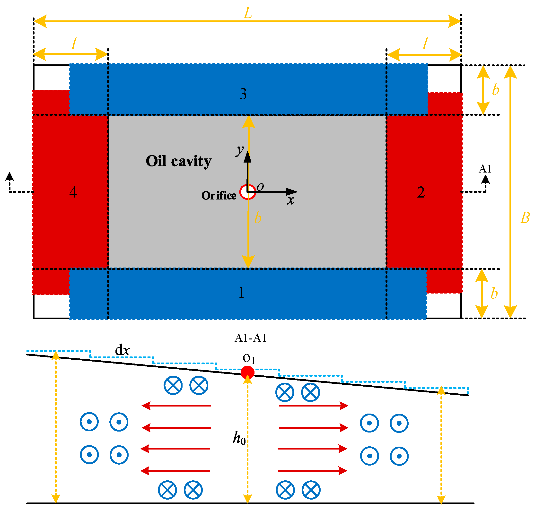
When the slider deflects, the oil film gap is no longer uniform, and the flow of lubricant in the oil film gap no longer follows the parallel plate formula [28]. Then the flow relationship needs to be deduced based on lubrication principles. As shown in Figure 2, the sealing surface is divided into four flat flow areas with lengths and widths L and B, respectively, and the sealing edges have lengths and widths l and b, respectively. The oil in basins 1 and 3 flows parallel to the y-axis, i.e., the blue arrows in the view A1-A1, and the oil in basins 2 and 4 flows along the x-axis direction, i.e., the red arrows in view A1-A1.
When the pitch angle of the oil pad around the y-axis is β, the oil film gap can be expressed as h ( x ) = h 0 + x β . Assuming that the flow rates out of the four regions are Q1, Q2, Q3 and Q4, respectively, the differential method is used to transform the tilted flat plate into an infinite number of tiny parallel flat plates with flow length dx and gap thickness h(x). Then, according to the parallel plate metric [28], it is obtained that:
d P d x = 12 μ ( B b ) h 3 ( x ) Q 2 = 12 μ ( B b ) h 3 ( x ) Q 4 P 0 b = 12 μ h 3 ( x ) d x d Q 3 = 12 μ h 3 ( x ) d x d Q 1
In Equation (2), P is the pressure value at the calculated position, P0 is the internal pressure in the oil chamber and μ is the oil viscosity.
Integrating over Equation (2), when x = ± L 2 l 2 , P = P 0 ; x = ± L 2 , P = 0 , Equation (3) can be deduced as
P 0 = 12 μ Q 2 B b x = L 2 l 2 x = L 2 1 h 0 + β x 3 d x = 12 μ Q 4 B b x = L 2 l 2 x = L 2 1 h 0 + β x 3 d x Q 1 = Q 3 = P 0 12 μ b x = L 2 l 2 x = L 2 l 2 h 0 + β x 3 x d x
Taking into account that β is a very small quantity, a simplification of the above equation yields the following flow equation for each basin:
Q 1 = Q 3 = L l h 0 3 P 0 12 μ b
Q 2 = P 0 B b h 0 + β L 2 l 2 h 0 + β l 2 2 12 μ l Q 4 = P 0 B b h 0 β L 2 l 2 h 0 β l 2 2 12 μ l
In summary, the total flow rate out of the rectangular oil pad when the pitch angle along the y-axis is β is:
Q d β = P 0 L l h 0 3 6 μ b + P 0 B b h 0 3 1 + β 2 2 L 3 l 4 h 0 2 l 6 μ l
Similarly, when the angle of torsional oscillation of the rectangular oil pad along the x-axis is α:
Q d α = P 0 B b h 0 3 6 μ l + P 0 L l h 0 3 1 + α 2 2 B 3 b 4 h 0 2 b 6 μ b

2.2. Calculation of the Load-Bearing Characteristics of the Rectangular Oil Pad

Assuming that the oil supply pressure of the small-hole throttling rectangular oil pad is Ps, the initial pressure of the oil chamber is P0, the initial oil film gap is h0, the flow coefficient of the small-hole throttle is η, the bore diameter is d, and the time-varying normal load F(t) and the pitch deflection load Mβ(t) exist at the center of mass of the slider, the variation in the oil film gap and the tilt angle of the rectangular oil pad are hF(t) and β(t), respectively, and the total flow rate of the oil pad is Q(t) and the pressure is P(t).
According to the law of conservation of flow, the flow rate Qd(t) out of the rectangular oil pad, the flow rate Qin(t) into the pad from the small orifice throttle and the flow rate Qh(t) extruded from the slider movement satisfy the following equation:
Q d ( t ) = Q i n ( t ) + Q h ( t )
The load carrying characteristics of the rectangular oil pad are discussed below for normal and eccentric loads, respectively:
  • Calculation of normal bearing characteristics
When the action of the slider by the external force F(t) is considered, h(t) = h0hF(t), then the terms in Equation (8) are
Q d t = P t h 3 t B b l + L l b 6 μ Q i n t = η π d 2 4 2 P s P t ρ Q h t = B L h ˙ t
Combine the coefficients in Equation (9): Q a ¯ = η π d 2 4 2 ρ , Q b ¯ = B b l + L l b 6 μ
By substituting Equation (9) into Equation (8), we obtain
Q a ¯ P s P 0 + Δ p ( t ) = Q b ¯ P 0 + Δ P ( t ) h 3 ( t ) + B L h ˙ F t
Then we apply the Taylor expansion to Equation (10) at (hF(0), p(0)) when t = 0, hF(t) = 0, p(t) = 0 is:
Q a ¯ Δ P ( t ) 2 P s P 0 = Q b ¯ h 0 3 Δ P ( t ) + 3 Q b ¯ P 0 h 0 2 h F ( t ) + B L h ˙ F t
The force f(t) on the rectangular oil pad at moment t is as follows:
f ( t ) = f 0 + Δ f ( t ) = f 0 + A e Δ P ( t )
In Equation (12), Ae = (Bb)(Ll) is the effective bearing area of the rectangular oil pad.
According to Newton’s second law, it is known that:
M h ¨ F ( t ) = F ( t ) M g + f 0 + f ( t ) = F ( t ) + f ( t )
Combining Equation (11) with Equation (13) yields:
M h ¨ F ( t ) + A e B L Q b ¯ h 0 3 + Q a ¯ 2 P s P 0 h ˙ F t + 3 A e Q b ¯ P 0 h 0 2 Q b ¯ h 0 3 + Q a ¯ 2 P s P 0 h F ( t ) = F ( t )
Then, the stiffness k and damping c of the rectangular oil pad are:
k = 3 A e Q b ¯ P 0 h 0 2 Q b ¯ h 0 3 + Q a ¯ 2 P s P 0 c = A e B L Q b ¯ h 0 3 + Q a ¯ 2 P s P 0
2.
Calculation of deflection load resistance
From the analysis above, it can be seen that when the slider is subjected to the external moment Mβ(t), the terms in Equation (8) are:
Q d t = P t L l h 0 3 6 μ b + B b h 0 3 1 + β 2 2 L 3 l 4 h 0 2 l 6 μ l Q i n t = η π d 2 4 2 P s P t ρ Q h t = L l 2 B b β ˙ 8  
Bring Equation (16) into Equation (8):
Q a ¯ P s P 0 + Δ P ( t ) = P 0 + Δ P ( t ) ( L l ) h 0 3 6 μ b + B b h 0 3 1 + β 2 2 L 3 l 4 h 0 2 l 6 μ l L l 2 B b 8 β ˙
Applying the Taylor expansion to Equation (17) at (β(0), ΔP(0)) when t = 0, β(t) = 0, ΔP(t) = 0, gives:
Q a ¯ 2 p s p 0 Δ P ( t ) = ( L l ) h 0 3 6 μ b + ( B b ) h 0 3 1 + β 0 2 l ( 2 L 3 l ) 4 h 0 2 6 μ l Δ P ( t ) P 0 β 0 h 0 ( B b ) ( 2 L 3 l ) 12 u Δ β ( t ) L l 2 B b 8 Δ β ˙ ( t )
Therefore:
Δ P ( t ) = P 0 β 0 h 0 ( B b ) ( 2 L 3 l ) 12 u Δ β ( t ) + L l 2 B b 8 Δ β ˙ ( t ) Q a ¯ 2 p s p 0 + ( L l ) h 0 3 6 μ b + ( B b ) h 0 3 1 + h 0 2 l ( 2 L 3 l ) 4 h 0 2 6 μ l
The pitching support moment mβ(t) of the rectangular oil pad to the center of the slider is:
m β ( t ) = m β , 0 + Δ m β ( t ) = 0 + d s Δ P x d s
In Equation (20), the initial pitch moment mβ,0 is 0, Po(t) is the value of the pressure change in the oil chamber, x is the distance from each point on the rectangular oil pad to the z-axis and ds is the differential area of the rectangular oil pad.
It follows from Newton’s second law that:
J β ¨ ( t ) = M β ( t ) m β ( t )
Bring Equation (19) and Equation (20) into Equation (21):
M β ( t ) = J β ¨ ( t ) + L l 4 B b 2 32 Q a ¯ 2 p s p 0 + ( L l ) h 0 3 6 μ b + ( B b ) h 0 3 1 + β 0 2 l ( 2 L 3 l ) 4 h 0 2 6 μ l β ˙ ( t ) + P 0 β 0 h 0 ( B b ) 2 ( 2 L 3 l ) ( L l ) 2 48 u Q a ¯ 2 p s p 0 + ( L l ) h 0 3 6 μ b + ( B b ) h 0 3 1 + β 0 2 l ( 2 L 3 l ) 4 h 0 2 6 μ l β t
Thus, when the pitch deflection load is applied to the rectangular oil pad, the angular stiffness kβ and the angular damping cβ are:
k β = P 0 β 0 h 0 ( B b ) ( 2 L 3 l ) 48 u Q a ¯ 2 p s p 0 + ( L l ) h 0 3 6 μ b + ( B b ) h 0 3 1 + β 0 2 l ( 2 L 3 l ) 4 h 0 2 6 μ l c β = L l 4 B b 2 32 Q a ¯ 2 p s p 0 + ( L l ) h 0 3 6 μ b + ( B b ) h 0 3 1 + β 0 2 l ( 2 L 3 l ) 4 h 0 2 6 μ l
Similarly, when the torsional deflection load is applied to the rectangular oil pad, the angular stiffness kα and the angular damping cα are:
k α = P 0 α 0 h 0 ( L l ) ( 2 B 3 b ) 48 u Q a ¯ 2 p s p 0 + ( B b ) h 0 3 6 μ l + ( L l ) h 0 3 1 + α 0 2 b ( 2 B 3 b ) 4 h 0 2 6 μ b c α = B b 4 L l 2 32 Q a ¯ 2 p s p 0 + ( B b ) h 0 3 6 μ l + ( L l ) h 0 3 1 + α 0 2 b ( 2 B 3 b ) 4 h 0 2 6 μ b

3. Algorithm Validation

3.1. Verification of Normal Characteristic Calculations

To verify the reasonableness of the calculated results of the normal characteristics of the single rectangular oil pad, the normal stiffness and damping results of the single rectangular oil pad were extracted using the pad parameters of the lateral guide in the literature [29] as input, and the normal calculated stiffness and calculated damping of the single rectangular oil pad were obtained according to Equation (24). In addition, CFD simulation was used to apply a sinusoidal disturbance of 5 mm to the initial oil film with a thickness of 25 μm, and the simulation results of the normal stiffness and damping were compared with the former in a supplementary way.
Figure 3 shows the comparative results of the normal load carrying characteristics of a single rectangular oil pad. Within the same oil pad structure, oil supply pressure and dynamic viscosity, it can be seen that the calculated stiffness, the stiffness results in the literature3 and the simulated stiffness results are basically the same, but there are some differences in the damping results. Taking the CFD simulation results as a reference for comparison, the calculated damping (black solid arrow in the figure) is approximately 8% less than the simulated damping when the dynamic viscosity of the fluid is low, and the damping results in the literature (red curved arrow in the figure) is approximately 18.3% less than the simulated damping. As the dynamic viscosity of the fluid increases, the calculated damping deviates from the damping in the literature to within 20% of the simulated damping. The main reason for the analysis error is that the parallel plate flow calculation method simplifies the flow at the four corners of the rectangular oil pad, resulting in the difference in the calculation of the oil film pressure from the real situation.

3.2. Calculation and Validation of Deflection Load Resistance

The deflection resistance of a rectangular oil pad includes angular stiffness and angular damping, which are difficult to decouple for individual oil pad units. To this end, the CFD method is used to validate our calculation of angular stiffness and angular damping. The relationship between oil pad deflection angle and oil film gap is established by coordinate transformation [30]. Then considering a little disturbance of α , β , α ˙ , β ˙ respectively under equilibrium state, we calculate the moment increments of m α and m β by calculus. Finally, the angular stiffness and the angular damping are calculated as follows:
k α = m α Δ α k β = m β Δ β c α = m α Δ α ˙ c β = m β Δ β ˙
The structural parameters of a single rectangular oil pad are taken from Table 1 and the angular stiffness and angular damping of the pad are solved by numerical calculation and simulation analysis, respectively. The CFD simulation analysis method and specific examples have been described in detail in the literature [31].
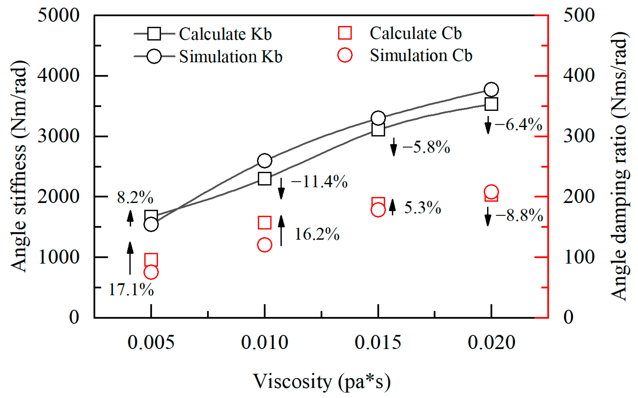
Figure 4 shows the calculation results of a single rectangular oil pad against pitch deflection. It can be seen that, under the same oil pad parameters, the results obtained by the calculation in this paper are closer to the simulation analysis results. Under different oil dynamic viscosities, the trends are basically the same, with a maximum deviation of 11.4% for angular stiffness and 17.1% for angular damping. The differences between the calculated results and the simulated results are mainly caused by two aspects: (1) the complex diffusive flow process at the four corners of the rectangular oil pad is still idealized when deriving the pressure flow relationship equation for the inclined flat plate. (2) the higher order non-linear term of the flow balance equation is omitted when building the calculation model for the deflection load resistance of the oil pad.
By comparing the results of deflection load resistance of a single rectangular oil pad obtained by different calculation methods, it can be seen that the numerical calculation model derived in this paper can effectively reflect the angular static and dynamic load carrying capacity of a single rectangular oil pad. Although the accuracy of the results is not as good as that of CFD full flow field simulation method, the calculation method of the deflection resistance of rectangular oil pad established in this paper can be easily used for design evaluation and parameter sensitivity analysis as an engineering approximation.

4. Results and Discussion

4.1. Analysis of the Anti-Deviation Load Capability of Single Oil Pad

For hydrostatic guide ways supported by multiple oil pads, two parts of resistance moment are generated because of the deviation load acting on the slider:
  • Anti-deviation load torque of single oil pad
  • Support torque of each oil pad relative to the center of mass of the slider
Take an open-hydrostatic slider supported by two adjacent rectangular oil pads (Figure 5) as an example. The distance l between two oil pad centers is 0.1~0.4 m. Assuming that the normal bearing capacity of the two oil pads is the same as the anti-deviation load capability, the oil film gap between oil pad 1 and oil pad 2 changes 5~20 μm when the slider deflects 1 × 10⁻⁴ rad under the external eccentric load.
It can be seen that when the external deviation load acts on the slider, the anti-eccentric moment generated by the oil pad itself is 0.1~1 N·m, while the support moment of a single oil pad relative to the center of mass of the slider is 0.5~400 N·m. Therefore, for the support system containing more than one rectangular oil pads, when l is small, the individual oil pad’s own anti-deviation load capability in the support system is relatively large (20%), and its role cannot be ignored. So, when designing the normal bearing capacity of the hydrostatic oil pad, it is necessary to take into account its anti-deviation load capability. When l is relatively large, the main source of anti-eccentric moment of the support system is the oil pad stiffness, and the anti-eccentric moment generated by the angular stiffness is relatively small.

4.2. Analysis of Factors Influencing the Anti-Deflective Load Characteristics

According to the aforementioned theoretical derivation, the anti-deflective load characteristics of the rectangular oil pad are mainly related to the oil supply pressure, small hole diameter, oil pad size and aspect ratio. Therefore, the influence law of the above important parameters on the angular stiffness and angular damping of the rectangular oil pad is studied to provide a basis for optimizing the anti-deflective load characteristics of the rectangular oil pad.

4.2.1. Feed Pressure

Adjusting the feed pressure of the rectangular oil pad to 0.5~5 MPa, we can obtain the angular stiffness and angular damping of the rectangular oil pad under different supply pressure. As can be seen from Figure 6, increasing the feed pressure of the rectangular oil pad can increase the load-bearing pressure of the pad, which significantly improves the angular stiffness of the pad. During this process, there is a small fluctuation (about 10%) in the angular damping of the oil pad, which indicates that the angular damping of the oil pad is not sensitive to the oil supply pressure. In addition, when the feed pressure is within 1 MPa, the pitch angle stiffness is basically the same as the torsion angle stiffness. As the feed pressure increases, the difference between the two stiffness increases gradually. It indicates that the rectangular oil pad has better anti-pitch eccentric load characteristics under large feed pressure.

4.2.2. The Diameter of Orifice

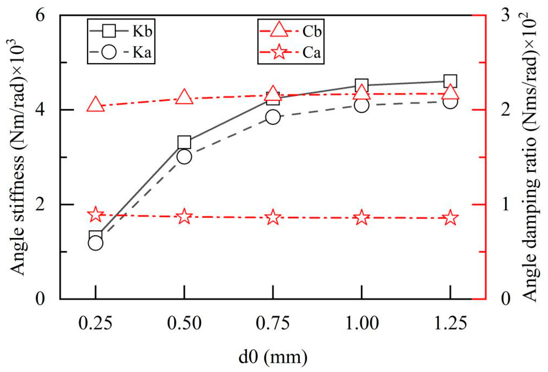
Adjusting the micro-hole to the common engineering value (0.25 mm~1.25 mm), we can obtain the effect law of the diameter of orifice on the angular stiffness and angular damping of rectangular oil pad. As the diameter of the micro-hole increases, the angular stiffness of the rectangular oil pad gradually increases at the beginning, then tends to level off. However, the angular damping has little change during the process. In general, the diameter of orifice should be designed for optimal throttling (The diameter of orifice should be 0.5 mm). From Figure 7, if the diameter of orifice increases from 0.5 mm to 0.75 mm, the pitch angle stiffness and torsion angle stiffness increases from 3.32 × 10³ and 3.01 × 10³ Nm/rad to 4.24 × 10³ Nm/rad and 3.85 × 10³ Nm/rad, respectively. With a small impact on the throttling characteristics, the anti-deviation load capability of the rectangular oil pad is improved significantly.

4.2.3. Oil Pad Dimensions and Aspect Ratio

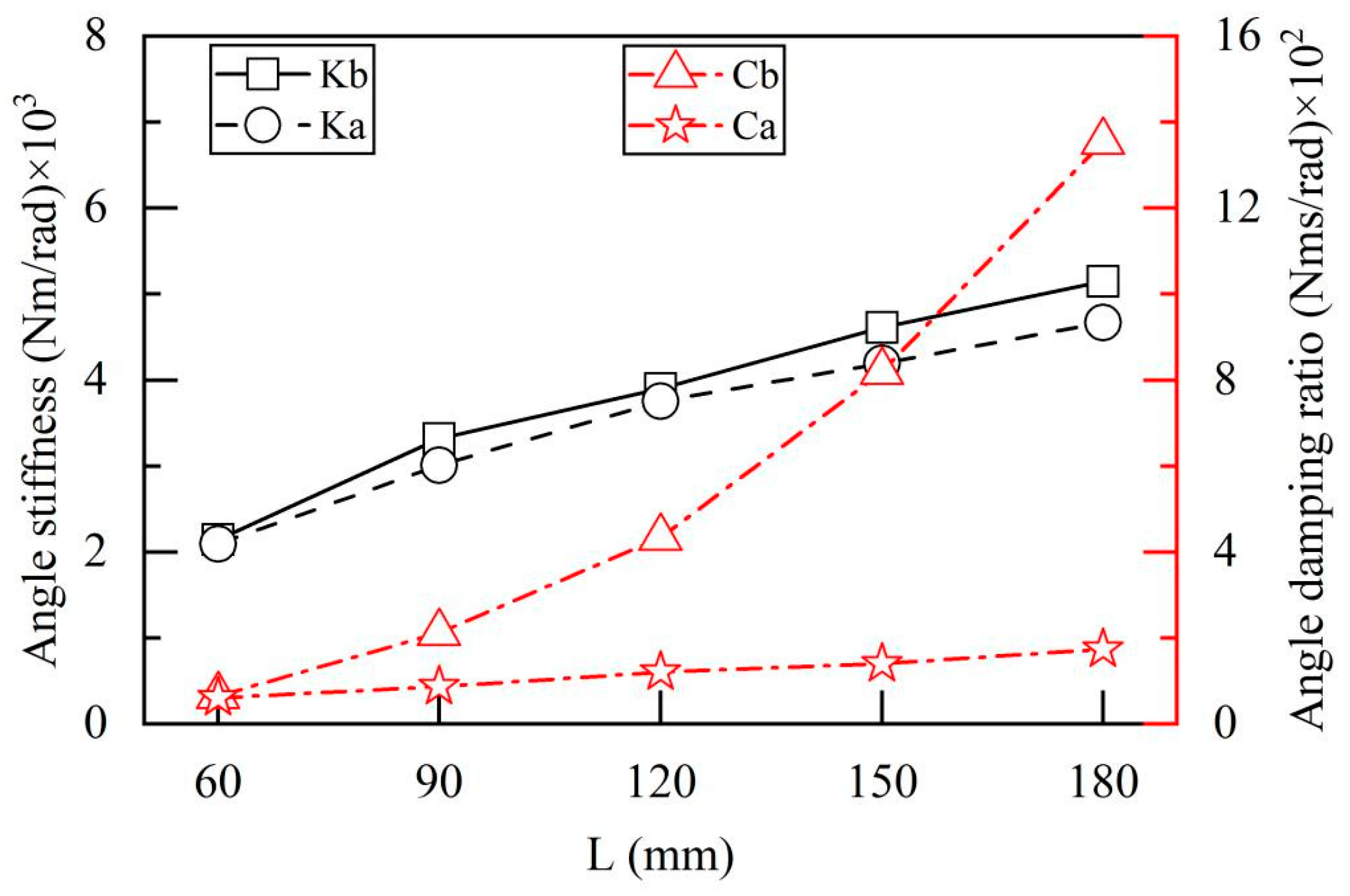
The influence of the length and width of the rectangular oil pad on its angular stiffness and angular damping is shown in Figure 8. Increasing the length of the rectangular oil pad can significantly enhance the angular stiffness and pitch angular damping in both directions. When the length of the oil pad is increased from 60 mm to 180 mm, the pitch angular damping increases from 65.9 Nm·s/rad to 1354.7 Nm·s/rad, indicating that increasing the length of the rectangular oil pad within a certain range is beneficial to improving its dynamic anti-eccentric load capacity. Its physical significance is that the equivalent acting span of the oil pad in this direction is raised, and under the same eccentric load moment, the oil film gap of the oil pad will change less, thus showing better angular static and dynamic characteristics.
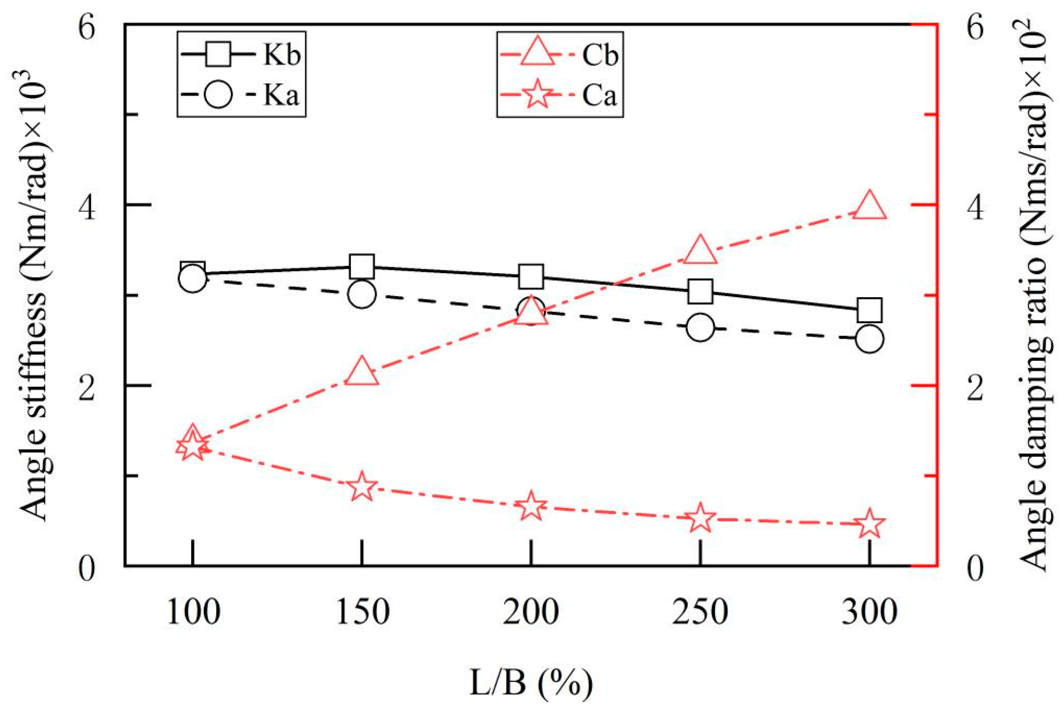
In order to further analyze the comprehensive effect of rectangular oil pad size on its anti-eccentric load capacity, the effects of different aspect ratios on the diagonal stiffness and angular damping under the same pad area were analyzed. As shown in Figure 9, with the increase in the length width ratio of the rectangular oil pad, the angular stiffness and torsional swing angle damping generally show a downward trend. During this process, the pitch angle damping increases continuously. When the aspect ratio increases from 100% to 300%, the pitch angle damping increases by about three times. It can be seen that the increase in the length width ratio of the rectangular oil cushion sacrifices some of the anti-eccentric load capacity and the dynamic eccentric load capacity in the torsional direction. However, the suppression effect of dynamic bias load in pitch direction is significantly improved. For the hydrostatic support system bearing the far end torque, under the condition of determining the bearing area of the oil pad, the dynamic mechanical characteristics can be improved by increasing the length width ratio of the rectangular oil pad, while meeting the static support capacity.

5. Conclusions

In this study, a typical rectangular hydrostatic oil pad unit was adopted as the research object, and a calculation model for the anti-eccentric load characteristics of the rectangular hydrostatic oil pad was theoretically derived. The static and dynamic eccentric load characteristics were analyzed, and the key conclusions are summarized as follows:
  • The calculated values of angular stiffness and angular damping for a single oil pad are in good agreement with the simulation results, verifying the accuracy of the proposed mathematical model. However, due to the idealization of the complex flow behavior at the four corners of the rectangular oil pad, high-order nonlinear terms in the flow balance equation were neglected, which introduces a minor deviation in the model.
  • For a support system with multiple oil pads, when the center-to-center distance between adjacent oil pads is small, the anti-eccentric load capacity of individual oil pads within the system is substantial, and their contribution cannot be overlooked. Therefore, when designing the normal load-carrying capacity of a hydrostatic oil pad system, its eccentric load-carrying capacity must be taken into account simultaneously.
  • The anti-eccentric load capacity of the rectangular oil pad can be significantly enhanced by increasing the oil supply pressure and optimizing the orifice diameter. In contrast, adjustments to the oil pad diameter, oil pad dimensions, and length-to-diameter ratio affect both the normal load-carrying capacity of the oil pad and its eccentric load-carrying capacity in specific directions. Specifically, increasing the oil supply pressure to above 3 MPa is beneficial for improving its eccentric load-carrying capacity; under the premise of ensuring static load-carrying capacity, a moderate increase in the orifice diameter also contributes to enhancing anti-eccentric load performance. Thus, during the design of rectangular oil pads, parameter optimization should be conducted based on specific application scenarios to improve the comprehensive load-carrying characteristics of the rectangular oil pad.

Author Contributions

Methodology, M.L.; Software, M.L.; Validation, M.L., Y.D. and J.W.; Formal analysis, J.W.; Resources, Y.D.; Data curation, M.L.; Writing—original draft, M.L.; Writing—review & editing, M.L.; Visualization, J.W.; Supervision, Y.D. All authors have read and agreed to the published version of the manuscript.

Funding

This work was supported by the State Key Laboratory of Mechanical System and Vibration (Grant No. MSVZD202503).

Data Availability Statement

The raw data supporting the conclusions of this article will be made available by the authors on request.

Conflicts of Interest

The authors declare no conflicts of interest.

Glossary

The following symbols are mainly used in this manuscript:
h(x)The oil film gap
PThe pressure value at the calculated position
P0The internal pressure in the oil chamber and the oil viscosity
μ The oil viscosity
βPitch angle in X direction
α Pitch angle in y direction
k normal stiffness
c normal damping value
k α y-direction angular stiffness component
k β x-direction angular stiffness component
c α y-direction angular damping value component
c β x-direction angular damping value component

References

  1. Nguyen, M.T.; Pham, V.H.; Tran, V.T.; Bui, T.A. Displacement Analysis of a Hydrostatic Spindle: An Experimental Investigation. Eng. Technol. Appl. Sci. Res. 2024, 14, 16962–16969. [Google Scholar] [CrossRef]
  2. Nguyen, M.T.; Tran, T.H.; Le, D.D.; Tran, D.T.; Bui, D.T.; Anh, B.T. The Influence of Capillary Geometry on the Stiffness of Hydrostatic Bearings in MediumSized Cylindrical Grinding Machines: A Simulation Analysis. Eng. Technol. Appl. Sci. Res. 2024, 14, 15993–15999. [Google Scholar] [CrossRef]
  3. Guo, M.H.; Rong, Y.M.; Huang, Y.; Feng, X.L.; Hu, H.D.; Wu, C.Y.; Zhang, G.J. Ultrafast laser-chemical modification hybrid fabrication of hydrostatic bearings with a superhydrophobicity solid-liquid interface. Sci. China (Technol. Sci.) 2024, 67, 696–708. [Google Scholar] [CrossRef]
  4. Marov, A.; Bokova, T.; Bokov, P.; Volkov, N. Experimental correction of the known procedure for calculating hydrostatic bearings operating in a heavy liquid-metal coolant. AIP Conf. Proc. 2023, 2697, 6. [Google Scholar] [CrossRef]
  5. Liu, H.; Wang, G.; Ke, J.; Yu, L. Research on the anti-sticking characteristics of water hydraulic piston friction pairs with hydrostatic bearing. Lubr. Sci. 2013, 25, 453–462. [Google Scholar] [CrossRef]
  6. Yu, X.; Du, B.; Meng, X.; Qiao, W.; Sun, Y.; Ma, W.; Sun, K.; Dai, R.; Jia, W.; Jiao, J.; et al. Dynamic Characteristics of Hydrostatic Thrust Bearing With Tilting Oil Pad Under Eccentric Load. J. Tribol. 2025, 147, 91104. [Google Scholar] [CrossRef]
  7. Bambhania, M.P.; Doshi, N. Optimization of Film Thickness for Hydrostatic Circular Pad Bearing Used in V-25 vertical Turning Machine. Int. J. Mech. Eng. Robot. 2013, 1, 118–121. [Google Scholar] [CrossRef]
  8. Zhang, Y.; Wu, Y.; Li, J.; Wang, M.; Quan, Z. Thermal Characteristics of Oil Film in Critical Lubrication State of Heavy Hydrostatic Bearing. Recent Pat. Mech. Eng. 2024, 17, 304–311. [Google Scholar]
  9. Liu, T.; Bei, Z.; Wang, H.; Duan, R.; Chen, F.; Zhang, J. Study on microgroove working surface in hydrostatic bearing for oil film heat suppression. Appl. Therm. Eng. 2025, 266, 125618. [Google Scholar] [CrossRef]
  10. Zhang, Y.; Li, J.; Wu, Y.; Wang, M.; Kong, P. Study of the Lubricity of Oil Film at Constant Cutting Speed Under Different Loads of a Hydrostatic Turntable. Tribol. Trans. 2023, 66, 135–143. [Google Scholar] [CrossRef]
  11. Zhang, Y.; Tao, J.; Ni, S.; Zhao, R. Mechanical Performance Analysis of Hydrostatic Thrust Bearing under Microbevel Parameters. Recent Pat. Eng. 2023, 19, e240223214025. [Google Scholar] [CrossRef]
  12. Tian, Z.; Cao, H.; Huang, Y. Static characteristics of hydrostatic thrust bearing considering the inertia effect on the region of supply hole. Proc. Inst. Mech. Eng. Part J J. Eng. Tribol. 2019, 233, 188–193. [Google Scholar] [CrossRef]
  13. Zhang, W.; Han, L.; Qian, L. Application of anti-eccentric open hydrostatic guideway in vertical lathe. Int. Conf. Adv. Compos. Mater. Manuf. Eng. 2020, 612, 32073. [Google Scholar] [CrossRef]
  14. Poole, W.; Chetta, G. Eccentric end wear in cylindrical roller bearings can be predicted and prevented. In Proceedings of the 19th Joint Propulsion Conference, Seattle, WA, USA, 27–29 June 1983. [Google Scholar] [CrossRef]
  15. Huang, H.C.; Yang, S.H. Thrust-Bearing Layout Design of a Large-Sized Hydrostatic Rotary Table to Withstand Eccentric Loads for Horizontal Boring Machine Applications. Lubricants 2022, 10, 49. [Google Scholar] [CrossRef]
  16. Foltýn, J.; Maccioni, L.; Michalec, M.; Concli, F.; Svoboda, P. Uncertainty analysis of hydrostatic bearing working conditions with experimental, CFD, and analytical approach. Forsch. Im Ingenieurwesen 2025, 89, 67. [Google Scholar] [CrossRef]
  17. Abdullah, R.; Trimulyono, A.; Samuel; Adietya, B.A. Numerical simulation of sloshing with floating baffles using smoothed particle hydrodynamics. IOP Conf. Ser. Earth Environ. Sci. 2025, 1461, 12007. [Google Scholar] [CrossRef]
  18. Michalec, M.; Foltn, J.; Svoboda, P.; Křupka, I.; Hartl, M. Experimental Comparison of Hydrostatic Bearing Pad Geometry Optimization Approaches Under Static Conditions; International Symposium on Industrial Engineering and Automation; Springer: Cham, Switzerland, 2024. [Google Scholar] [CrossRef]
  19. Gao, W.; Yu, X.; Wang, P.; Jiang, H. Deformation behavior prediction and structural optimization of vertical hydrostatic guideway ram in vertical lathe. J. Braz. Soc. Mech. Sci. Eng. 2025, 47, 352. [Google Scholar] [CrossRef]
  20. Yu, X.; Sun, F.; Zhou, D.; Huang, D.; Zhan, S.; Han, F.; Jiao, J.; Jiang, H. Research on influencing factors of oil film temperature field characteristics for adaptive hydrostatic thrust bearing. Proc. Inst. Mech. Eng. Part B J. Eng. Manuf. 2024, 238, 1727–1735. [Google Scholar] [CrossRef]
  21. Guo, C.S.; Cui, Y. Study on the Hydrostatic Slide Film Temperature Field and Bearing Capacity of Precision Grinding Machine; Springer: Berlin/Heidelberg, Germany, 2016. [Google Scholar] [CrossRef]
  22. Yu, X.; Li, S.; Chen, M.; Wang, S.; Han, Z.; Tang, B.; Wang, J.; Jiang, H.; Jia, W. Prediction and improvement on anti-eccentric load characteristics of high-speed and heavy-type hydrostatic bearing. J. Braz. Soc. Mech. Sci. Eng. 2022, 44, 558. [Google Scholar] [CrossRef]
  23. Yu, X.; Shao, M.; Yang, X.; Li, L.; Lin, Y.; Lan, Z.; Li, E.; Dai, R.; Jia, W.; Wang, J.; et al. Investigation on lubrication characteristics and deformation control of hydrostatic bearing workbench. Proc. Inst. Mech. Eng. Part J J. Eng. Tribol. 2025, 239, 133–150. [Google Scholar] [CrossRef]
  24. Zhang, Y.; Zhao, R.; Tao, J.; Wang, M.; Kong, P. Effect of cutting and feed speed on lubrication performance of large hydrostatic turntable with constant linear velocity. Lubr. Sci. 2024, 36, 330–340. [Google Scholar] [CrossRef]
  25. Liu, Z.; Guo, J.; Wang, Y.; Xiangmin, D.; Wu, Y.; Yan, Z.; Jinlong, G. Influence of rotational speed of a heavy-duty hydrostatic turret on bearing performance under tilt. Ind. Lubr. Tribol. 2020, 72, 575–579. [Google Scholar] [CrossRef]
  26. Du, Y.; Mao, K.; Liu, H.; Mao, X.; Li, Z. A simplified analytical method for the pressure of tilt hydrostatic journal bearing. Ind. Lubr. Tribol. 2018, 70, 993–1001. [Google Scholar] [CrossRef]
  27. Tripkewitz, F.A.; Fritz, M.; Weigold, M. Experimental study on tilting stiffness of oil hydrostatic shallow recess thrust bearings. MM Sci. J. 2021, 2021, 5000–5007. [Google Scholar] [CrossRef]
  28. Chen, Y. Principle and Design of Hydrostatic Bearing; National Defense Industry Press: Beijing, China, 1980. [Google Scholar]
  29. Qi, E. Modelling on Static & Dynamic Performance And Geometric Error Analysis Of Ultra Precision Vertical Linear Motion System. Ph.D. Thesis, Harbin Institute of Technology, Harbin, China, 2016. [Google Scholar]
  30. Pu, Y.; Zhang, X.; Zhang, F. Research on the Static and Dynamic Characteristics of Liquid Static Pressure Guides for Ultra Precision Machine Tools. Comb. Mach. Tool Autom. Process. Technol. 2020. [Google Scholar]
  31. Li, M.; Hu, Q. Research on rapid modeling and analysis method of hydrostatic bearing based on COMSOL Multiphysics. Hydraul. Pneum. 2020, 44, 95–100. [Google Scholar]
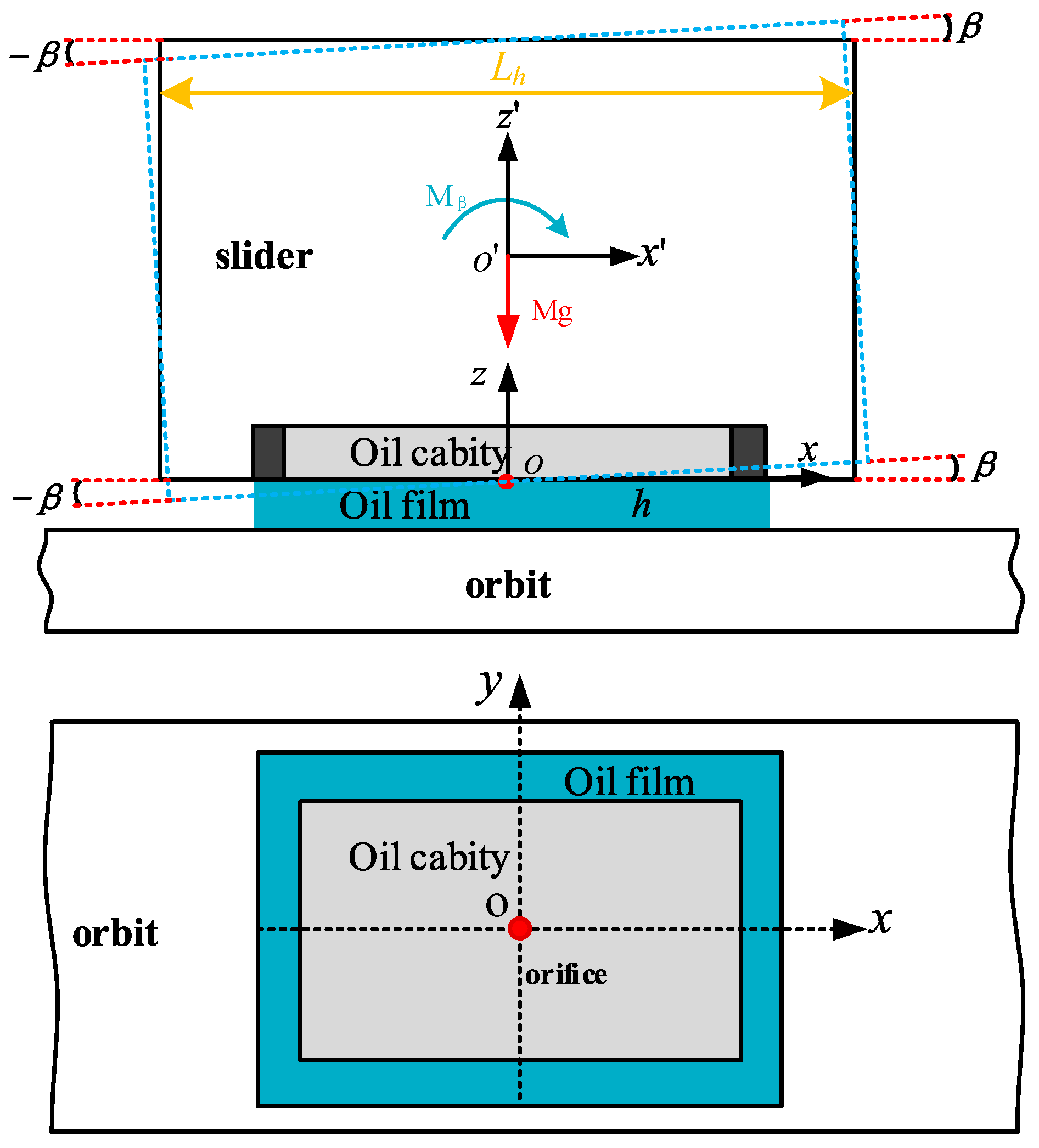
Figure 1. Diagram of the slider supported by a single rectangular oil pad.
Lubricants 13 00471 g001
Figure 2. Schematic diagram of the internal flow of the rectangular oil pad.
Lubricants 13 00471 g002
Figure 3. Normal bearing characteristics of single rectangular oil pads at different viscosities [29].
Lubricants 13 00471 g003
Figure 4. Pitch deflection resistance of a single rectangular oil pad at different viscosities.
Lubricants 13 00471 g004
Figure 5. Working diagram of multi-oil pad-supported hydrostatic guide.
Lubricants 13 00471 g005
Figure 6. Angular stiffness and angular damping of rectangular oil pad under different feed pressure.
Lubricants 13 00471 g006
Figure 7. Angular stiffness and angular damping of rectangular oil pad for different diameter of orifice.
Lubricants 13 00471 g007
Figure 8. Influence of rectangular oil pad size on angular stiffness and angular damping.
Lubricants 13 00471 g008
Figure 9. Rectangular oil pad length to width ratio.
Lubricants 13 00471 g009
Table 1. Rectangular oil pad parameters.
ParametersNumerical Values
L (mm)90
B (mm)60
l (mm)15
b (mm)15
h0 (me)40
d0 (mm)0.5
Ps (MPa)1
Disclaimer/Publisher’s Note: The statements, opinions and data contained in all publications are solely those of the individual author(s) and contributor(s) and not of MDPI and/or the editor(s). MDPI and/or the editor(s) disclaim responsibility for any injury to people or property resulting from any ideas, methods, instructions or products referred to in the content.