Article

Fluid–Structure Interaction Mechanisms of Layered Thickness Effects on Lubrication Performance and Energy Dissipation in Water-Lubricated Bearings

1
State Key Laboratory of Maritime Technology and Safety, Wuhan University of Technology, Wuhan 430063, China
2
School of Transportation and Logistics Engineering, Wuhan University of Technology, Wuhan 430063, China
3
Reliability Engineering Institute, National Engineering Research Center for Water Transport Safety, Wuhan University of Technology, Wuhan 430063, China
4
School of Naval Architecture, Ocean and Energy Power Engineering, Wuhan University of Technology, Wuhan 430063, China
5
School of Mechanical Engineering, Zhengzhou University of Aeronautics, Zhengzhou 450046, China
*
Authors to whom correspondence should be addressed.
Lubricants 2025, 13(10), 445; https://doi.org/10.3390/lubricants13100445 (registering DOI)
Submission received: 27 August 2025 / Revised: 24 September 2025 / Accepted: 10 October 2025 / Published: 12 October 2025

Abstract

Traditional single-layer water-lubricated rubber or plastic bearings suffer from water film rupture, excessive frictional losses, and insufficient load-carrying capacity, which limit performance and service life in marine propulsion and ocean engineering. To address these issues, this study introduces an innovative laminated bearing consisting of a rubber composite layer and an ultra-high-molecular-weight polyethylene (UHMWPE) layer. A three-dimensional dynamic model based on fluid–structure interaction theory is developed to evaluate the effects of eccentricity, rotational speed, and liner thickness on lubrication pressure, load capacity, deformation, stress–strain behavior, and frictional power consumption. The model also reveals how thickness matching governs load transfer and energy dissipation. Results indicate that eccentricity, speed, and thickness are key determinants of lubrication and structural response. Hydrodynamic pressure and load capacity rise with eccentricity above 0.8 or higher speeds, but frictional losses also intensify. The rubber layer performs optimally at a thickness of 5 mm, while excessive or insufficient thickness leads to stress concentration or reduced buffering. The UHMWPE layer exhibits optimal performance at 5–7 mm, with greater deviations resulting in increased stress and deformation. Proper thickness matching improves pressure distribution, reduces local stresses, and enhances energy dissipation, thereby strengthening bearing stability and durability.

1. Introduction

Bearings are fundamental components of rotating machinery. They are extensively employed in high-load systems, such as ship propulsion, electric motors, numerical control equipment, and metallurgical rolling mills. Their principal function is to support both axial and radial loads. This function directly affects the operational stability and precision of mechanical systems [1,2]. Among the various types of bearings, sliding bearings are widely utilized. They stand out due to their compact design, smooth operation, and favorable adaptability to lubrication. However, conventional oil-lubricated sliding bearings, which typically combine mineral-based lubricants with metallic bearing shells, present several limitations. These include high resource consumption, significant environmental pollution, and insufficient thermal stability. The use and disposal of mineral oils entail substantial energy consumption and pollutant emissions. This poses challenges to achieving green development objectives under the “dual-carbon” strategy. Additionally, metallic bearing shells are vulnerable to corrosion and wear during extended service. They also exhibit a strong dependence on scarce metallic resources. Under high-speed and high-load operating conditions, the lubricating oil film may deteriorate due to a reduction in viscosity. This results in lubrication failure, severely compromising bearing lifespan and system efficiency [3]. Oil-lubricated bearings also raise potential leakage risks and ecological hazards, particularly in marine or water-exposed environments [4]. To mitigate environmental impacts, regulatory measures have been enacted in regions such as Europe and the United States. These regulations restrict the operation of oil-lubricated vessels in ecologically sensitive waters. As a result, they accelerate research into alternative lubricants and advanced material systems. Water, as a sustainable lubrication medium, has garnered increasing attention since the 1930s. This is due to its abundance, renewability, and excellent thermophysical properties [5]. Over the past century, water-lubricated bearings have been successfully implemented in critical applications. These include ship propulsion, offshore platforms, hydroelectric generators, and pump systems. These applications demonstrate reliable operational performance and strong environmental compatibility [6,7]. Nevertheless, compared to oil-based lubrication, water exhibits lower viscosity. This leads to a limited load-carrying capacity of the lubricating film. Under extreme conditions—including high speed, low temperature, and heavy loading—the hydrodynamic water film is challenging to maintain stably. This increases the risk of operational failure [8]. Moreover, commonly used non-metallic liner materials possess relatively low elastic moduli and are prone to excessive deformation under load. Such deformation undermines the stability of liquid films and promotes localized wear. This impedes the broader application of water-lubricated bearings in high-reliability and long-service-life scenarios.
In recent years, enhancing the lubrication performance of water-lubricated bearings has become a prominent research focus globally. Current investigations predominantly concentrate on two principal strategies: structural optimisation and material modification [9,10]. Within the realm of structural optimisation, adjustments to geometric parameters—such as the thickness and hardness of the inner liner, radial clearance, length-to-diameter ratio—and surface characteristics—including surface roughness and texture features—have demonstrated efficacy in improving water film formation conditions and augmenting load-carrying capacity. Regarding material modification, researchers have applied physical and chemical techniques to alter bearing bush materials with the objectives of enhancing mechanical strength, optimising interfacial lubrication states, and achieving synergistic regulation of multiple performance attributes. These modifications indirectly contribute to improved load-carrying capacity and operational reliability of water-lubricated bearings. Significant theoretical and experimental advancements have been realized in structural design optimization, leading to a deeper understanding of bearing geometry, water film formation mechanisms, and fluid–structure interaction behaviors. For instance, Smith et al. [11] analysed grooved rubber-lined water-lubricated bearings and determined that the elastic modulus of the rubber material has a minimal influence on the minimum water film thickness; however, bearing load capacity decreases markedly with increasing clearance ratio and the number of grooves. Mallya et al. [12] examined the impact of lubricant flow regimes under turbulent conditions, demonstrating that the transition from laminar to turbulent flow effectively enhances load-carrying capacity. Kraker et al. [13,14] developed a mixed elastohydrodynamic lubrication model to systematically elucidate the effects of key parameters—elastic modulus, eccentricity, surface roughness, and radial clearance—on lubrication state evolution, distinctly identifying their respective influences on load-carrying performance and wear behaviour. Du et al. [15] conducted experimental investigations into the effects of journal misalignment and surface roughness on the performance of water-lubricated rubber bearings, confirming that both factors critically modulate water film thickness and pressure distribution. Yang et al. [16] employed a fluid–structure coupling model to systematically analyse the effects of various groove configurations on rubber bush deformation, water film pressure, and flow field distribution, proposing that a hybrid groove structure more effectively enhances lubrication performance. Li et al. [17] investigated the impact of rubber layer thickness on elastohydrodynamic lubrication, finding that moderate increases in thickness significantly improve the formation of a stable lubricating film. He et al. [18] performed combined theoretical and experimental studies on axially asymmetric groove structures, systematically analysing the effects of groove type, eccentricity ratio, rotational speed, and groove positioning on bearing dynamic response. Their findings indicate that asymmetric groove designs amplify localised hydrodynamic effects at the microscale, thereby substantially improving overall lubrication performance. In the domain of material modification, notable progress has also been achieved. Ma et al. [19] incorporated functional fillers, such as nanoparticles, into rubber matrices, markedly enhancing the material’s load-bearing capacity as well as its anti-friction and wear-resistant properties. Liu et al. [20,21,22], inspired by biomimetic lubrication principles, fabricated hydrated lubricating layers utilising hydrogels, microgels, and polymer brushes, successfully producing a variety of polymer-based water-lubricating materials. These materials adsorb water molecules to form stable hydration films, maintaining low friction coefficients and wear rates even under high contact loads, thereby exhibiting excellent lubrication performance and environmental compatibility. Qu et al. [23,24] developed molybdenum disulfide (MoS2) and carbon fibre (CF)-reinforced NBR/PU/EP interpenetrating network composites. Their study revealed that carbon fibres are highly dispersed within the matrix and exhibit a synergistic effect with MoS2, significantly reducing friction coefficients and wear volume, thus enhancing the tribological performance and service stability of the composite material.
Although groove structures, surface texturing, and liner geometry have been optimized, there is still limited research on material modification for better anti-friction and wear resistance. Most efforts focus on numerical simulations and experiments; however, the impact of material changes on lubrication remains unclear. Energy dissipation in multi-layer composite liners, which involve both soft and hard materials, is not fully understood, making it challenging to optimize water-lubricated bearings for reliability and longevity. Research on single-layer bearings is advanced, but work on stacked layers is just beginning, so the interactions between the fluid and structure, water film formation, and the effects of liner thickness are still uncertain. There is currently no unified theory to explain the dynamic responses and energy dissipation in these systems.
This study builds on current research by addressing technical challenges in water-lubricated bearings with a laminated structure. It investigates how thickness affects lubrication performance and energy dissipation. A fluid–structure interaction dynamic model systematically analyzes how the liner thickness ratio impacts water film pressure distribution, load-carrying capacity, and frictional power loss under varying eccentricity ratios and rotational speeds. The study explains lubrication behaviors and energy dissipation mechanisms driven by thickness effects, and examines how liner thickness shapes the bearing’s static structural response. The main objective is to establish a theoretical framework for analyzing thickness effects in laminated water-lubricated bearings, providing a scientific basis for optimizing multi-layer composite design and performance control. This work supports greater operational reliability and the broader application of these bearing systems in various engineering applications.

2. Theoretical Analysis of Water-Lubricated Bearings with a Layered Structure

In the theoretical analysis of multilayer composite water-lubricated bearings, the governing equations for the fluid and solid domains are formulated independently. This approach accurately represents the fundamental physical mechanisms that govern water film flow and the structural response of the liner. The fluid domain equations characterize the pressure distribution and flow dynamics within the water film. In contrast, the solid domain equations describe the stress, strain, and deformation behavior of the liner under external loading. By integrating boundary conditions across both domains, a comprehensive framework for fluid–structure interaction is developed. This framework facilitates precise and concurrent analysis of lubrication performance and structural behavior.

2.1. Governing Equations of the Fluid Domain

In analyzing the lubrication characteristics of multilayer composite water-lubricated bearings, the physical behavior of the fluid domain is effectively described using the principles of continuum mechanics. The primary governing equations encompass the continuity equation, the momentum conservation equation, and the energy conservation equation. Given that the temperature increase in such bearings under normal operating conditions is minimal, the effect of temperature variation on lubricant viscosity can be justifiably neglected. Furthermore, heat transfer between the fluid and solid domains is generally insignificant. Consequently, most lubrication models do not explicitly solve the energy equation [25,26].
Continuity Equation:
ρ t + · ( ρ V ) = 0
· ( a ) = d i v ( a ) = a x x + a y y + a z z
Momentum Conservation Equation:
t ( ρ v ) + · ( ρ v v ) = p + · ( τ ¯ ¯ ) + ρ g + F
where ρ is the fluid density; t is the velocity vector; v is the velocity vector; p is the static pressure; τ is the stress tensor; ρg and F represent the gravitational force and external body force, respectively.
The stress tensor is expressed as:
τ ¯ ¯ = μ [ v + v T 2 3 · v I ]
where μ is the dynamic viscosity of the fluid, and I is the unit tensor.
During shaft rotation and the development of hydrodynamic lubrication, cavitation frequently occurs. Cavitation is defined as the vaporization of a liquid and the formation of vapor bubbles within it. This happens when the pressure within the lubrication region falls below the liquid’s saturation vapor pressure. At a system temperature of 20 °C, the saturation vapor pressure of water is approximately 2340 Pa. If the local fluid pressure drops below this threshold, cavitation may be initiated. In severe cases, numerous microbubbles generated within the cavitation zone can rapidly expand. These bubbles may subsequently collapse in regions of elevated pressure, exerting substantial impact loads on the contact interface between the shaft and the multilayer liner structure. This phenomenon can not only rupture the lubrication film but also induce surface material fatigue, micro-crack formation, and delamination. As a result, it significantly degrades the operational performance and service life of the lubrication system. The Zwart–Gerber–Belamri (ZGB) model is commonly employed in numerical simulations to characterize the cavitation process [27]. The mathematical formulation of this model is presented as follows:
t ( α v ρ v ) + · ( α v ρ v v ) = R g R c
p p v , R g = 3 F e v a p α n u c ( 1 α v ) ρ v R b 2 3 × p v p ρ 1 p > p v , R c = 3 F c o n d α v ρ v R b 2 3 × p p v ρ 1
where α v is the vapor volume fraction; ρ v is the vapor density; Rg and Rc denote the mass transfer between the liquid and vapor phases during cavitation; Fevap is the vaporization coefficient, taken as 50; Fcond is the condensation coefficient, taken as 0.01; Rb is the bubble radius, taken as 1.0 × 10⁻⁶ m; α n u c is the nuclei volume fraction, taken as 5.0 × 10⁻⁴; ρ l is the liquid density; and p v is the cavitation pressure.

2.2. Solid Domain Control Equation

To enhance the operational stability, lubrication performance, and resistance to friction and wear of multilayer water-lubricated bearings under complex operating conditions, a double-layer composite liner structure was adopted for the non-metallic inner liner. This liner comprises two materials with distinct mechanical properties. These are specifically designed to achieve coordinated control over impact loading, frictional wear, and lubrication conditions. Liner 1 is positioned on the fluid-contacting side and is composed of an elastomer–plastic blend composite. Due to its excellent deformability, it effectively reduces film compression, absorbs micro-vibrations, and suppresses friction-induced instabilities. Liner 2 is located adjacent to the rigid support structure and is fabricated from UHMWPE. Its constitutive equation is formulated as follows [28]:
ε x = U x = 1 E [ σ x μ ( σ y + σ z ) ] ε y = V y = 1 E [ σ y μ ( σ x + σ z ) ] ε z = W z = 1 E [ σ z μ ( σ x + σ y ) ] γ x y = τ x y G , γ y z = τ y z G , γ z x = τ z x G
where U, V, and W are the displacements in the x , y , and z directions, respectively; ε x , ε y , ε z , γ x y , γ y z , and γ z x are the strain components at a point; σ x , σ y , σ z , τ x y , τ y z , and τ z x are the stress components at a point; μ is the Poisson’s ratio; and E is the elastic modulus.
When a hydrodynamic lubrication film is established between the shaft surface and the surface of Liner 1, the water film pressure applies a normal load directly onto the surface of Liner 1. This induces substantial elastic deformation under compressive stress. The ends of both Liner 1 and Liner 2 are constrained by fixed supports. During deformation, Liner 1 transmits the applied load to Liner 2 through their interfacial contact. However, energy dissipation within Liner 1 reduces the portion of the load transferred to Liner 2’s interface. As a result, only a fraction of the load causes deformation in Liner 2. These mechanical characteristics allow the overall deformation behavior of the liner system to be mathematically represented by the following equilibrium differential equation [29]:
E 2 ( 1 + μ ) ( 1 1 2 μ θ x + 2 U ) + f x = 0 E 2 ( 1 + μ ) ( 1 1 2 μ θ y + 2 V ) + f y = 0 E 2 ( 1 + μ ) ( 1 1 2 μ θ z + 2 W ) + f Z = 0
where θ = U x + V y + W z is the volumetric strain; 2 = 2 x 2 + 2 y 2 + 2 z 2 is the Laplace operator; and f x , f y , and f z are the body forces acting on the differential element in the x , y , and z directions, respectively.

3. Theoretical Physical Model of Water-Lubricated Bearings with a Laminated Structure

A theoretical physical model for laminated water-lubricated bearings was developed. This model integrates the geometric configuration and material parameter definitions. Furthermore, it addresses the implementation of boundary conditions and meshing strategies under fluid–structure interaction scenarios. Additionally, the model provides a comprehensive numerical solution procedure. As a result, this approach enables accurate representation of the bearing’s hydrodynamic behavior and structural response. It also clarifies the underlying coupling mechanisms. Overall, the framework supports detailed investigation of both the lubrication performance and the mechanical behavior of laminated water-lubricated bearings.

3.1. Bearing Structure

Unlike conventional single-layer water-lubricated bearings, the laminated design uses a dual-layer nonmetallic liner. This significantly enhances lubrication performance, mechanical response, and operational reliability. Traditional monolithic rubber or plastic liners often have limited load-carrying capacity. They are also prone to excessive deformation or failure under complex loading conditions. The laminated structure uses a soft–hard stiffness gradient. This promotes homogenization of hydrodynamic pressure, mitigates dynamic loads, and reduces stress concentrations. As a result, it enhances lubrication stability and improves structural integrity. For numerical modeling, three-dimensional fluid and solid domains were developed using SolidWorks 2022, as shown in Figure 1. The solid domain has a two-layer nonmetallic liner. The inner layer, adjacent to the rotating shaft and lubricant film, is a rubber-based composite. The outer layer, in contact with the rigid support, is made of UHMWPE. These two layers are bonded together to form a unified structure. Continuity of displacement, stress, and strain is maintained at the interface. This ensures smooth transitions and effective load transfer between the materials. The structural parameters of the laminated water-lubricated bearing and the physical properties of the liner layer are detailed in Table 1 and Table 2.
Table 1. Parameters of the inner lining of the water-lubricated bearing with a laminated structure.
ParameterWater FilmLining 1Lining 2
Inner diameter/mm151.2152162
Outer diameter/mm152162172
Radial clearance/mm0.4------
Eccentricity0.5~0.9------
Thickness/mm---3, 5, 7, 9, 11, 133, 5, 7, 9, 11, 13
MaterialsLiquid waterRubber-plastic blend composite materialsUHMWPE
Length/mm320320320
Table 2. Physical parameters of the laminated inner liner structure.
ParameterRubber-Plastic Blend Composite MaterialsUHMWPE
Density/(kg/m3)15001700
Elastic modulus/Mpa7.841000
Poisson’s ratio0.470.4

3.2. Boundary Conditions and Meshing

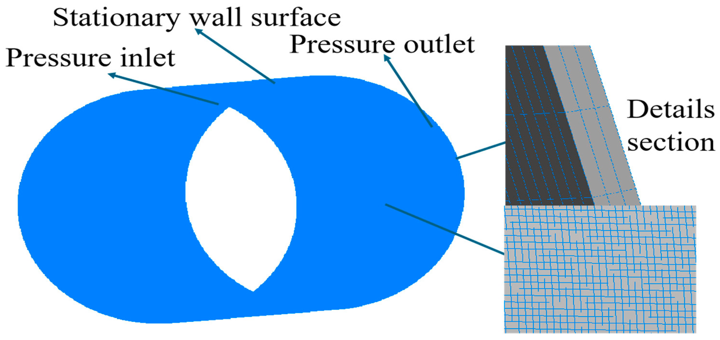
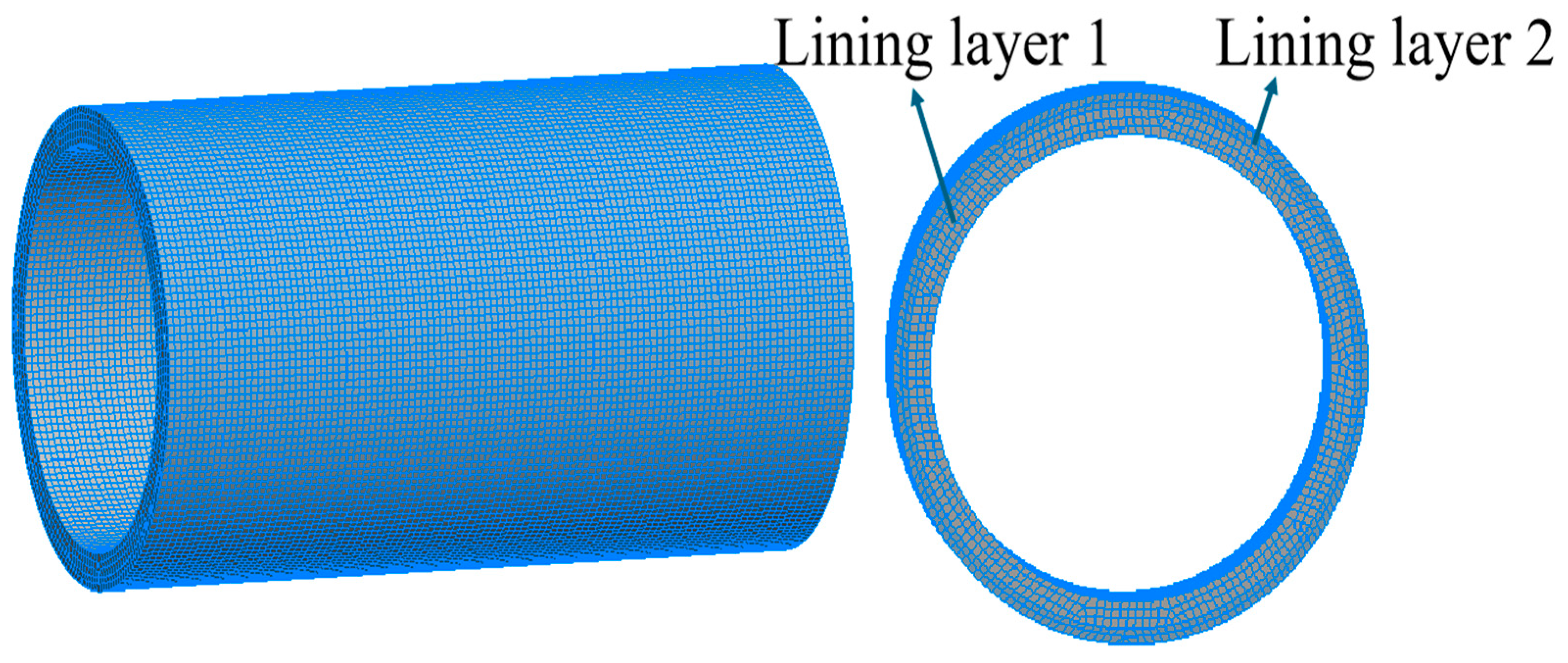
In engineering applications, the housing of water-lubricated bearings is rigidly mounted to the hull structure, and its deformation has a negligible impact on the global mechanical response; therefore, it is modeled as a rigid, fixed boundary in numerical simulations. Lubricating water enters the bearing clearance at the inlet, flows along the inner surface of liner 1, and exits at the outlet, forming a stable hydrodynamic film between the shaft journal and liner 1. The liner’s inner surface rotates with the shaft and is treated as a moving boundary, while the outer surface remains stationary and serves as a fixed boundary, as shown in Figure 2. To reflect in-service loading and constraints, a fully fixed constraint is applied to the outer surface of liner 2 in the solid domain, restricting all translational and rotational degrees of freedom along the x, y, and z axes; displacement constraints on the front and rear end faces of liners 1 and 2 limit motion in the x and y directions. A bonded contact is defined at the interface between the two liners to prevent relative sliding and separation, ensuring structural continuity of the laminate. The fluid-domain mesh for the water film is generated in Fluent Mesher. Three axially arranged layers of progressive refinement are deployed at the inlet and outlet to resolve local pressure gradients and velocity variations, and the core region is discretized using the Sweep method to ensure element quality and orthogonality. The solid-domain mesh in the Static Structural environment likewise adopts a Sweep strategy to maintain through-thickness continuity and node alignment across interfaces. A base element size of 3 mm is used, with local refinement at the contact interface and stress-concentration zones. Mesh-independence analysis reveals that the relative error in maximum water-film pressure across varying mesh densities remains below 1%, indicating a suitable balance between accuracy and efficiency. All meshes pass quality checks for orthogonal quality and skewness and meet the requirements for numerical simulation. Mesh configurations are illustrated in Figure 2 and Figure 3, and meshing parameters and statistics are summarized in Table 3.
Figure 2. Schematic diagram of water film grid.
Lubricants 13 00445 g002
Figure 3. Schematic diagram of the grid for the lining structure.
Lubricants 13 00445 g003

3.3. Solution Computation Flowchart

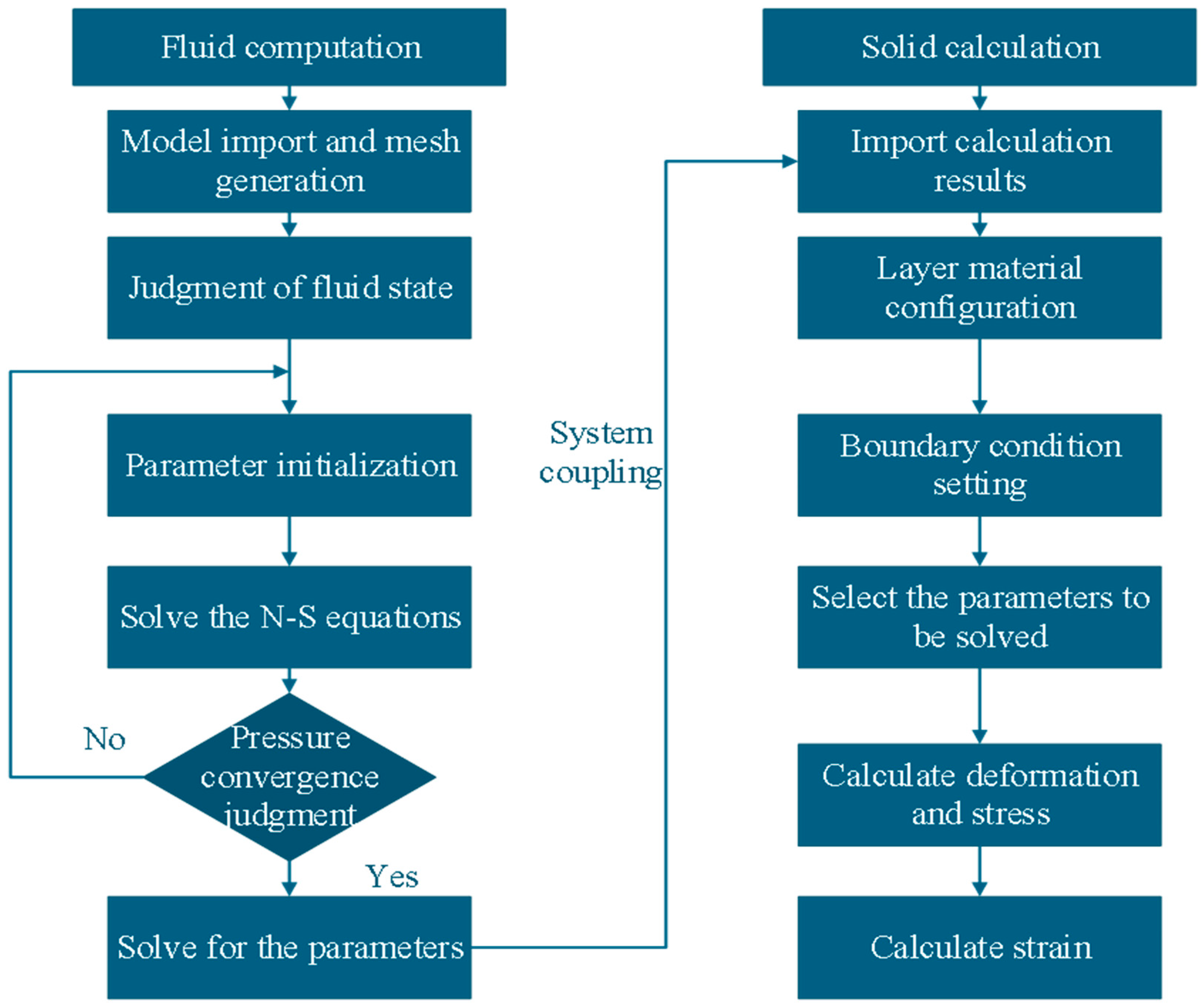
Figure 4 presents the computational methodology for analyzing the laminated water-lubricated bearing. This approach uses a fluid–structure interaction (FSI) framework to couple simulations of the fluid and solid domains. As a result, it evaluates both hydrodynamic lubrication and the liner’s structural response simultaneously. First, the bearing’s geometric model is developed and discretized through mesh generation. The lubricant’s physical properties help characterize the flow regime, informing the selection of governing equations and boundary conditions. Next, the Reynolds and Navier–Stokes equations are solved to determine the pressure distribution in the water film. Key performance metrics, such as load-carrying capacity and frictional behavior, are also evaluated. After the fluid domain analysis, material properties are assigned to the liner layers, and proper boundary conditions are set within the structural mechanics solver. The pressure field from the fluid domain is then transferred to the solid domain via the fluid–solid interface. This allows iterative calculation of stress, strain, and deformation in the liner. Critical mechanical parameters are ultimately extracted from the coupled simulation results to improve design optimization and enhance the reliability assessment of the laminated bearing structure.

4. Results and Discussion

4.1. Analysis of the Influence of Eccentricity on the Lubrication Performance

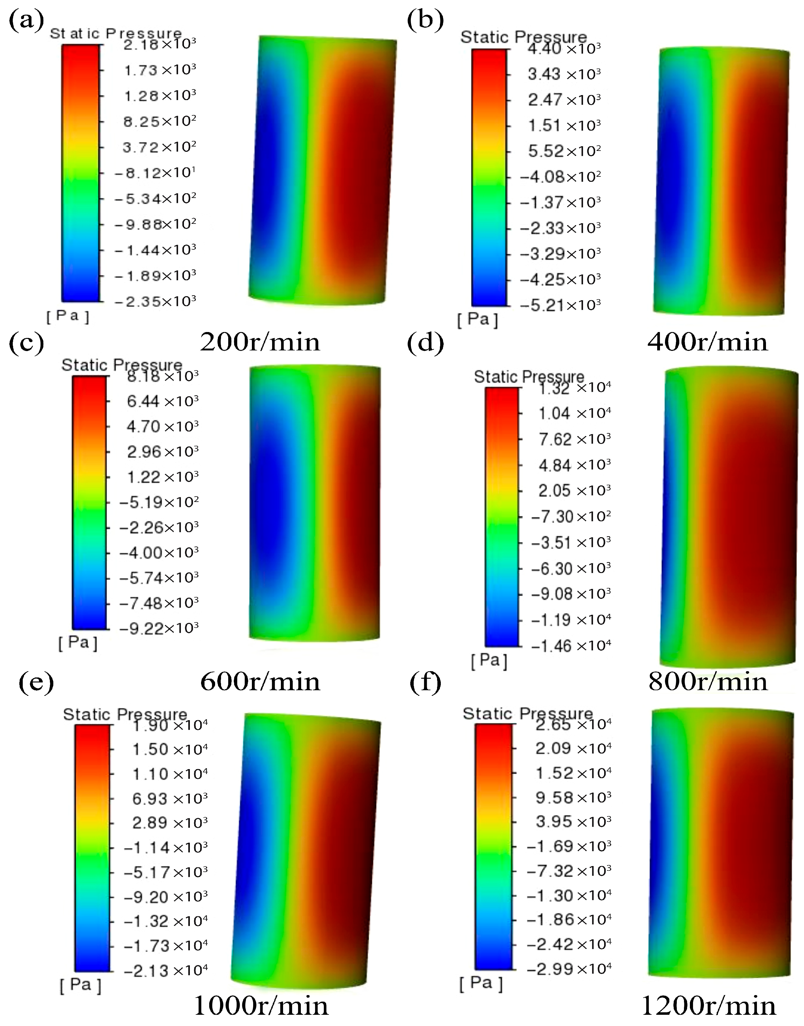
To examine the effect of eccentricity on the FSI characteristics of laminated water-lubricated bearings, a coupled fluid–structure dynamic analysis was conducted under representative operating conditions. In the simulation, Liner 1 was modeled as a rubber composite material. Liner 2 consisted of UHMWPE. Both layers had a uniform thickness of 5 mm. The rotational speed varied from 200 to 1200 r/min. The eccentricity ratio was maintained at 0.5. Figure 5 illustrates the resulting water film pressure distributions at each rotational speed. The findings indicate that convergent and divergent wedge-shaped regions formed on either side of the water film. These regions correspond to positive and negative pressure zones, which indicate a stable hydrodynamic lubrication regime. As the rotational speed increased, the pressure distribution went through distinct evolutionary stages. At 200 and 400 r/min, the pressure amplitude was low and the hydrodynamic effect was weak. At 600 r/min, the high-pressure region grew more pronounced, the negative pressure zone expanded, and lubrication stability improved. At 800 r/min, the pressure amplitude increased substantially. The contrast between high- and low-pressure regions intensified, and the load-carrying capacity was significantly enhanced. At 1000 and 1200 r/min, the pressure amplitude reached its peak. Localized high-pressure concentrations appeared, and the negative pressure zone further expanded, resulting in increased asymmetry in the pressure distribution. This behavior is mainly due to the greater centrifugal force at higher speeds. The increased force induces radial fluid accumulation along the outer periphery of the rotating shaft. This generates a high-pressure region. Areas farther from the rotation center experience pressure depletion, which amplifies the negative pressure and results in an asymmetric pressure field.
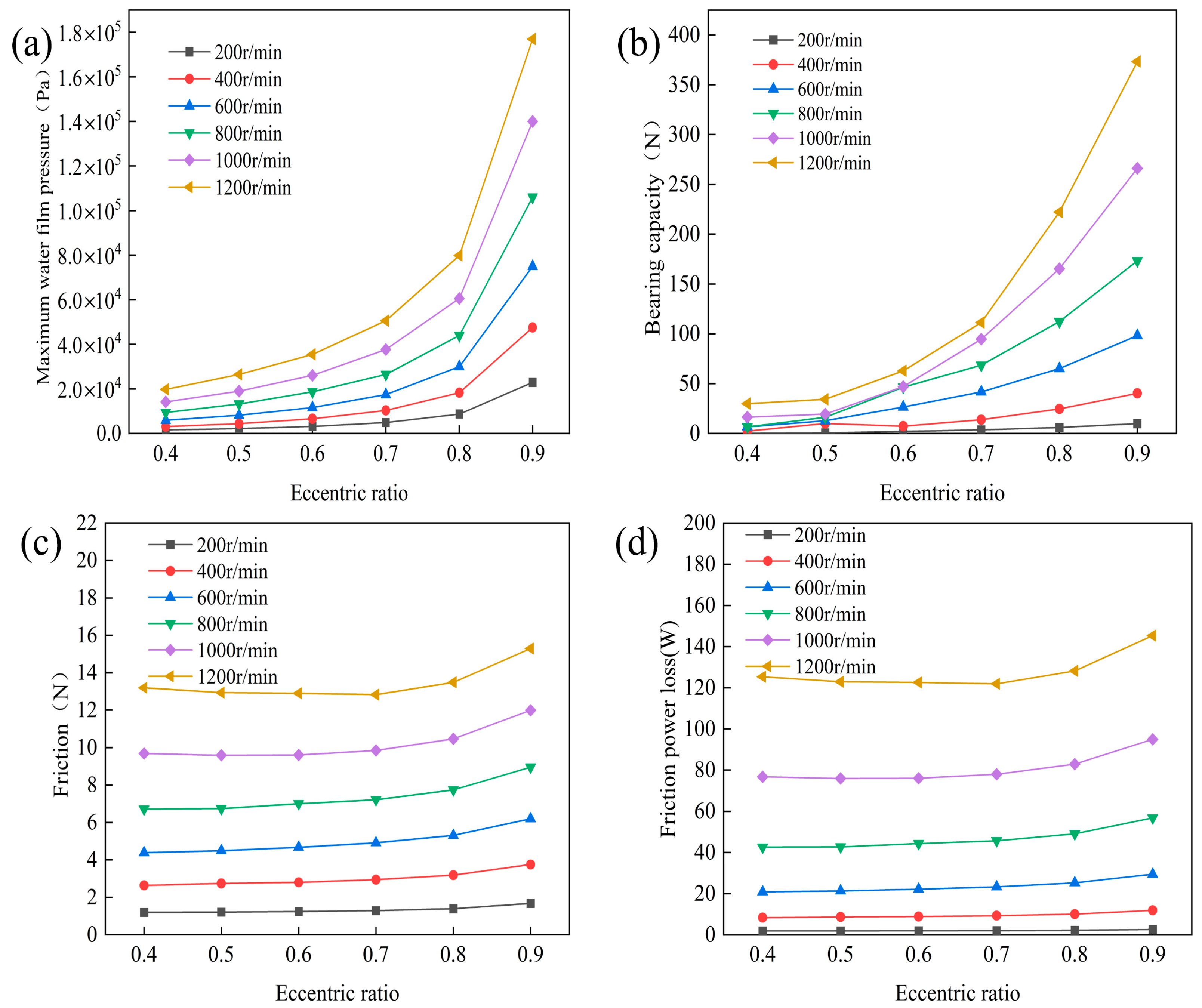
As depicted in Figure 6, the eccentricity ratio has a significant impact on the operational performance of laminated water-lubricated bearings at various rotational speeds. Figure 6a shows that, at a fixed rotational speed, the maximum water film pressure increases as the eccentricity ratio rises. This increase remains gradual when the eccentricity ratio is below 0.8. However, it accelerates notably beyond this value. When both rotational speed and eccentricity ratio are high, pressure levels become much higher than under low speed and low eccentricity. This underscores the amplifying impact of eccentricity on stress distribution. In Figure 6b, the load-carrying capacity increases steadily with eccentricity ratio for all speeds. The rate of growth becomes sharper as speed rises, particularly at 1000 r/min and 1200 r/min. This indicates a synergistic interaction between speed and eccentricity. Figure 6c indicates that the friction force generally increases with the eccentricity ratio. However, variations are minimal within the 200–600 r/min range, showing stable behavior at low speeds. The increase in friction force becomes more marked above 600 r/min. Figure 6d shows that the frictional power loss increases with the eccentricity ratio. The growth is moderate below 600 r/min, but sharpens above this point. This pattern reveals greater energy dissipation at high eccentricity and high speed. The eccentricity ratio is defined as the offset between the shaft and bearing center divided by the radial clearance. Under eccentric conditions, a converging-diverging lubrication wedge forms within the clearance. This creates a pressure gradient along the film thickness, producing hydrodynamic load support. As the eccentricity ratio increases, both the wedge effect and hydrodynamic pressure are strengthened. This significantly improves load capacity and is further assisted by stronger dynamic pressure effects at higher speeds. Meanwhile, the reduction in minimum film thickness leads to higher friction forces and power losses. When rotational speed surpasses a critical threshold, energy dissipation develops a convex upward trend [30,31,32].
Figure 7 illustrates the total deformation contour plot of the laminated water-lubricated bearing subjected to an eccentricity of 0.5, a rotational speed of 200 r/min, and equal layer thicknesses of 5 mm each. The results indicate that deformation is predominantly concentrated on the inner surfaces of both liner layers. Layer 1 exhibits a substantially greater deformation amplitude than Layer 2. Under these conditions, the maximum deformation of Layer 1 reaches 0.27923 μm. In contrast, the Layer 2 thickness is only 0.0078362 μm, which is approximately 35 times smaller. The minimum deformation in Layer 1 is 9.2881 × 10⁻⁵ μm. Layer 2, however, exhibits zero minimum deformation, indicating its superior structural stability and resistance to deformation. The color distribution in the contour map further reveals that regions depicted in red correspond to peak deformation values, primarily concentrated at the inner contact interfaces of the two layers. This phenomenon results from the radial pressure exerted by the hydrodynamic water film on the bearing liner during rotation of the shaft. Initially, this pressure acts on the inner surface of Layer 1. Due to its viscoelastic properties, Layer 1 absorbs and dissipates a significant portion of the fluid-induced pressure. This leads to pronounced local deformation, which is subsequently transmitted across the interface to Layer 2. However, due to its higher stiffness, Layer 2 experiences only minimal deformation near the loaded region. These findings suggest that, under low-speed, symmetric, and equal-thickness conditions, Layer 1 primarily accommodates flexible deformation. In contrast, Layer 2 serves as a stabilizing substructure by constraining the propagation of deformation and providing mechanical support.
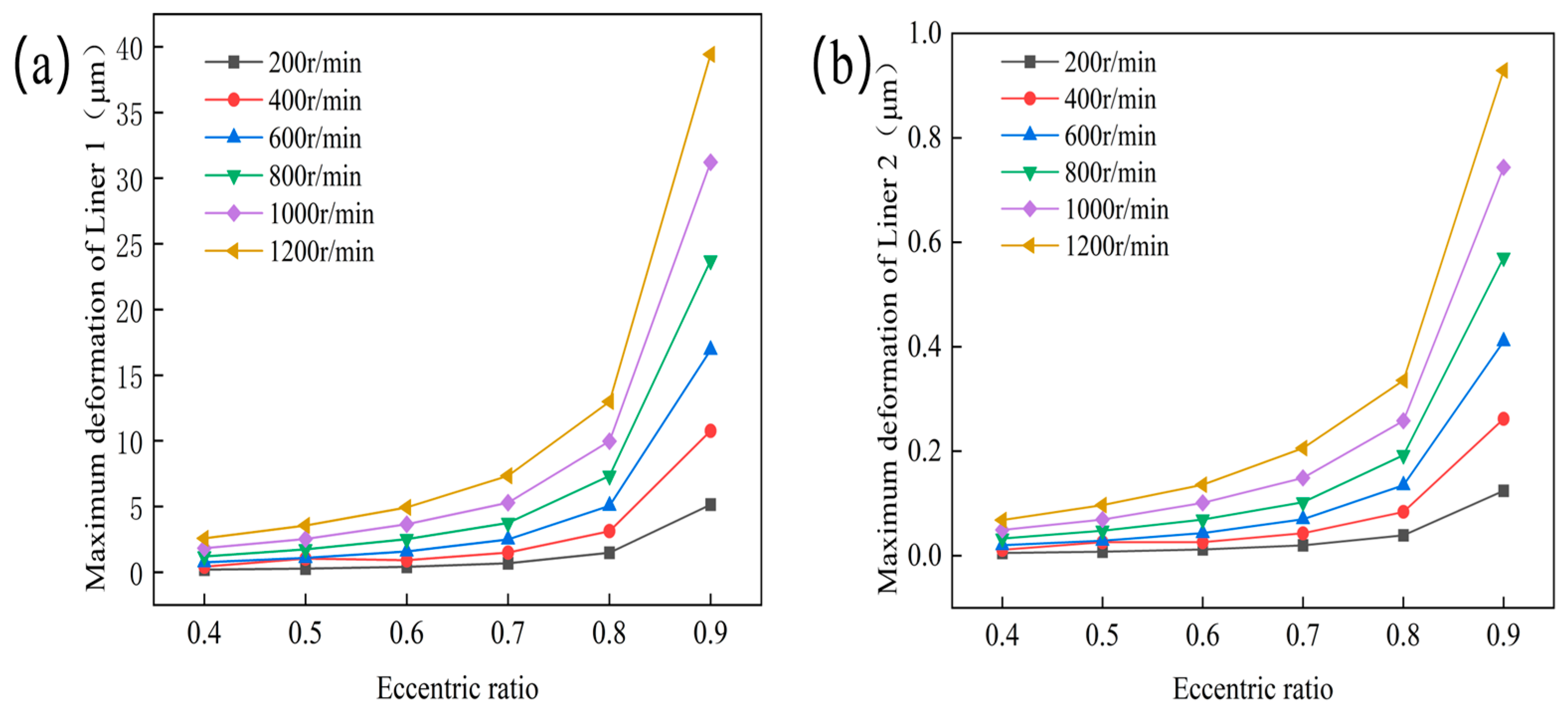
Figure 8 depicts the effect of eccentricity on the maximum deformation of various liner materials in a laminated water-lubricated bearing. The results indicate that the maximum deformation in both liners rises with eccentricity, confirming a clear positive correlation. Figure 8a,b detail the maximum deformation for Liner 1 and Liner 2, respectively, across different rotational speeds. A comparative analysis shows that Liner 1 consistently exhibits greater maximum deformation than Liner 2 under all tested conditions. For example, at an eccentricity of 0.4 and 200 r/min, Liner 1 deforms by 0.19381 μm, while Liner 2 deforms only 0.000528 μm. When eccentricity increases to 0.9 and rotational speed reaches 1200 r/min, Liner 1’s deformation reaches 39.429 μm, more than forty times higher than Liner 2’s 0.92904 μm. These differences demonstrate that Liner 2 significantly outperforms Liner 1 in structural rigidity and deformation resistance. The deformation trend is nonlinear: below an eccentricity of 0.8, deformation increases gradually, but beyond this point, both liners show rapidly accelerating deformation, indicating a major change in each liner’s structural stiffness under high eccentricity and increased material stress. Rotational speed also significantly impacts deformation; below 600 r/min, deformation increases slowly, highlighting limited fluid–structure interaction, while above 600 r/min, deformation increases rapidly, indicating that hydrodynamic pressure and centrifugal forces dominate liner deflection [33]. In summary, eccentricity and rotational speed jointly shape maximum deformation of laminated bearing liners, with their combined impact being most pronounced at higher values. The pronounced difference in sensitivity between the liners underscores the critical role of material choice in bearing design.
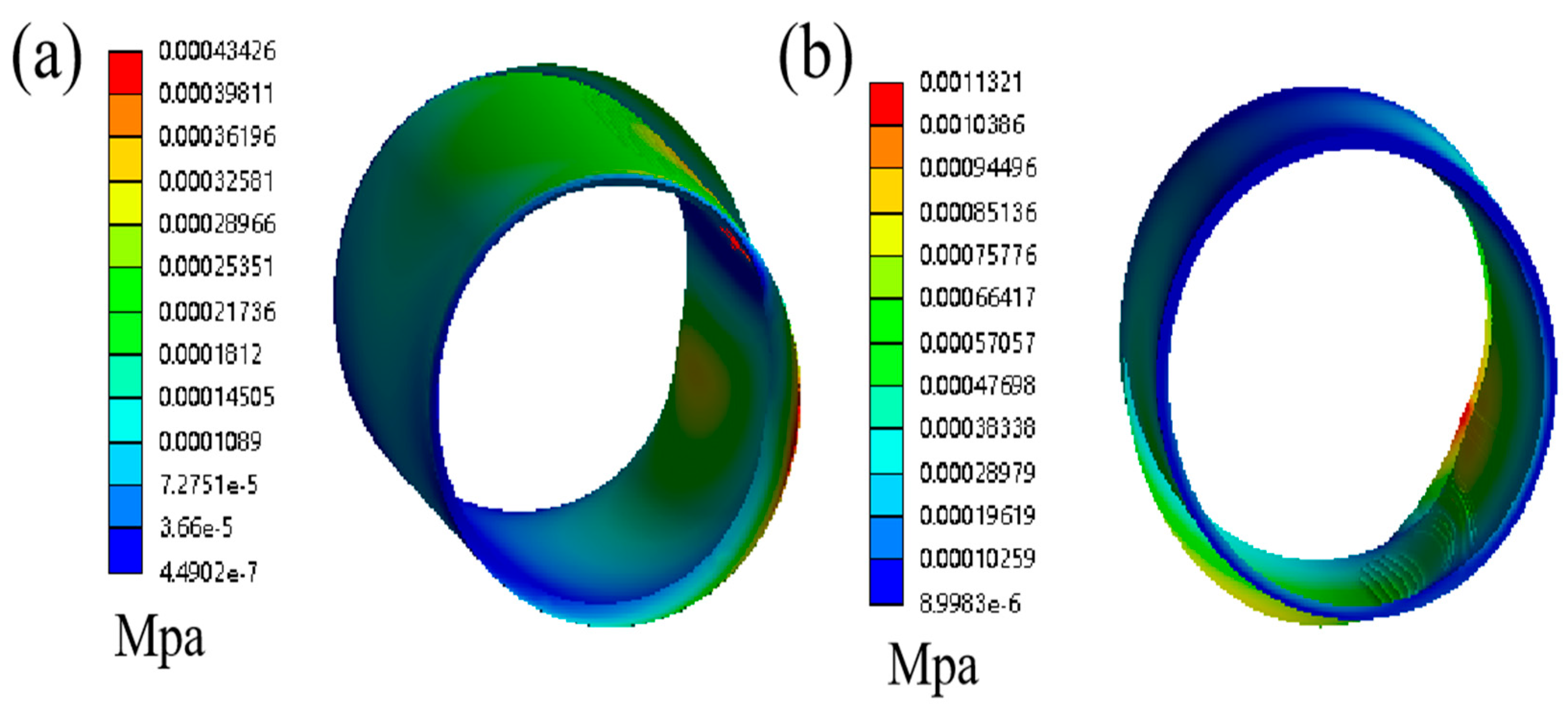
Figure 9 illustrates the stress distribution within a laminated water-lubricated bearing. This analysis uses equal layer thicknesses of 5 mm for both Liner 1 and Liner 2, an eccentricity ratio of 0.5, and a rotational speed of 200 r/min. As depicted in Figure 9a, a localized region of elevated stress appears on the outer surface of Liner 1. The maximum equivalent stress is 0.43426 kPa. Conversely, Figure 9b indicates that Liner 2 experiences a higher maximum equivalent stress of 1.13121 kPa. However, the overall stress distribution in Liner 2 remains relatively uniform, without significant stress concentration. This phenomenon results from the asymmetric wedge-shaped water film formed by shaft rotation under eccentric loading. The film generates coexisting regions of positive and negative pressure circumferentially. In the positive-pressure region, hydrodynamic pressure transmits normal loads across the interface and superimposes tangential frictional stresses. This combination causes localized increases in stress. In contrast, the negative-pressure region exhibits substantially reduced stress levels. Differences in material properties also influence this behavior. Liner 1 is characterized by a low elastic modulus and a high Poisson’s ratio. As a result, it undergoes considerable elastic deformation under localized loading, leading to stress concentration. In comparison, Liner 2 possesses greater stiffness. Although its peak stress surpasses that of Liner 1, the stress gradient is mild. This promotes a more uniform stress distribution and effective load transfer. Consequently, Liner 1 is more susceptible to localized stress concentration, whereas Liner 2 facilitates stress homogenization. These differences underscore distinct structural response characteristics between the two materials.
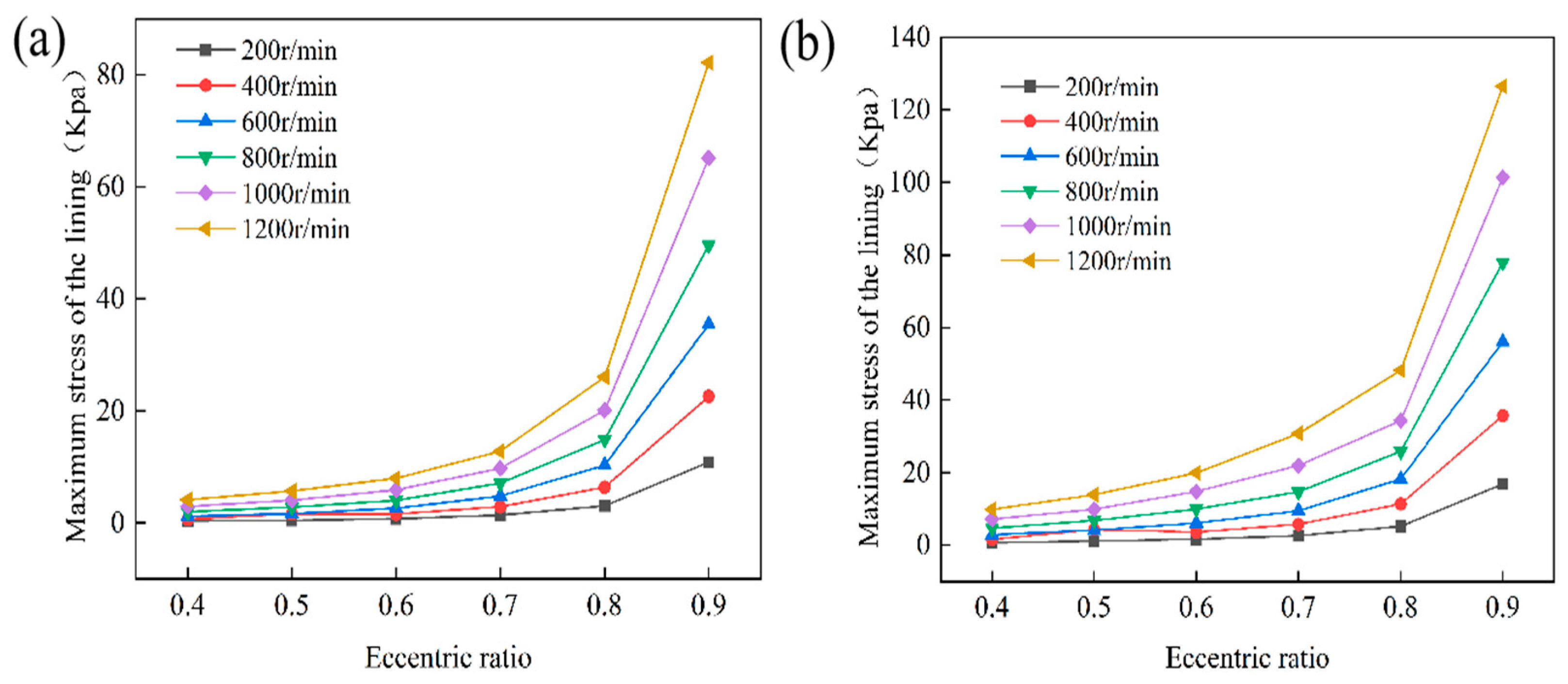
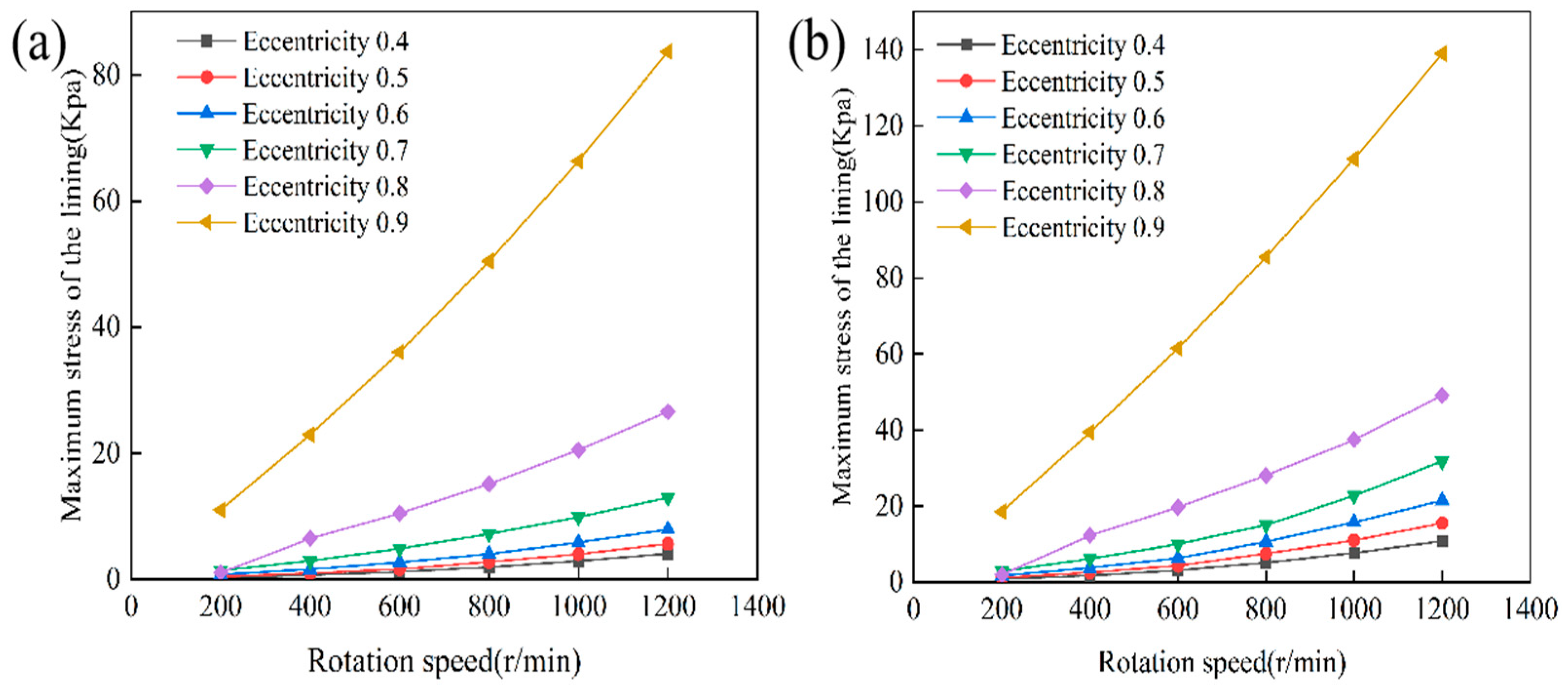
Figure 10 depicts the effect of eccentricity on the maximum stress observed in a laminated water-lubricated bearing. The findings indicate that, at a constant rotational speed, the maximum stress in both Liner 1 and Liner 2 increases as eccentricity rises. When eccentricity remains below 0.8, the stress increment is approximately linear and relatively gradual. However, beyond this threshold, the rate of increase accelerates markedly. For a given material, the disparity in stress across varying rotational speeds becomes more pronounced as the speed increases. At a fixed eccentricity, the maximum stress also escalates with rotational speed. Below 600 r/min, the increase is moderate, whereas above 600 r/min, the growth trend intensifies significantly. A comparative analysis further reveals that the maximum stress in Liner 2 consistently exceeds that in Liner 1 by a substantial margin. This indicates a higher load-carrying stiffness in Liner 2. This phenomenon can be explained by the sequence of load transmission and energy dissipation mechanisms within the system. The mechanical load generated by shaft rotation initially acts upon the hydrodynamic water film at the inner surface. Here, a portion of the energy dissipates through fluid viscous shear. The residual load is then transferred to Liner 1, which, due to its viscoelastic properties, dissipates additional energy through stress–strain hysteresis and internal friction resulting from molecular chain segment motion. This reduces the load transmitted to the underlying layer, helping to mitigate stress concentration. The attenuated energy is subsequently conveyed to Liner 2. The UHMWPE layer further absorbs and dissipates energy due to its high stiffness and intrinsic structural damping characteristics. Consequently, the system establishes a three-tiered energy attenuation mechanism. This comprises fluid damping, viscoelastic damping in Liner 1, and structural damping in Liner 2 [34,35].
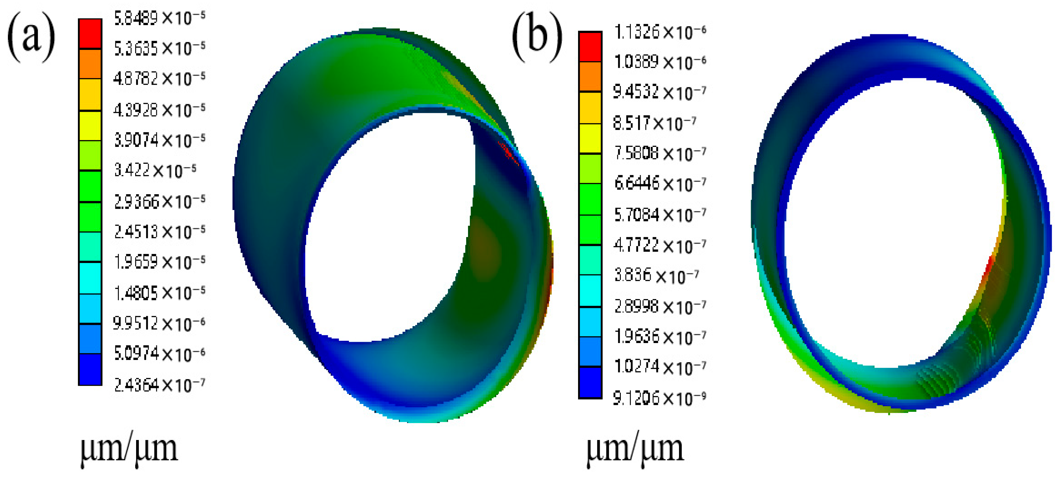
Figure 11 illustrates the strain distribution in a laminated water-lubricated bearing. The test conditions are equal linear thickness (5 mm), an eccentricity ratio of 0.5, and a rotational speed of 200 r/min. The results indicate that the maximum strain in Liner 1 reaches 5.849 × 10⁻⁵. In contrast, Liner 2 reaches only 1.1326 × 10⁻⁶, which is about one order of magnitude lower. This disparity is due to the distinct material properties of the liners. Liner 1 has a lower elastic modulus and viscoelastic damping properties. As a result, this layer dissipates a significant portion of the applied energy under external loading and develops greater strain. Liner 2, with a higher elastic modulus, primarily serves as a rigid load-bearing layer, exhibiting significantly less deformation. The strain contour map also shows that the high-strain region in Liner 1 is more extensive. This region has a gradual color gradient and continuous distribution, indicating widespread elastic deformation. In contrast, the high-strain region in Liner 2 is highly localized. It displays a sharp color transition, reflecting concentrated deformation at certain sites. These findings underscore a clear functional difference between the layers. Liner 1 acts as a flexible, energy-dissipating component. Liner 2 provides rigidity and mechanical support.
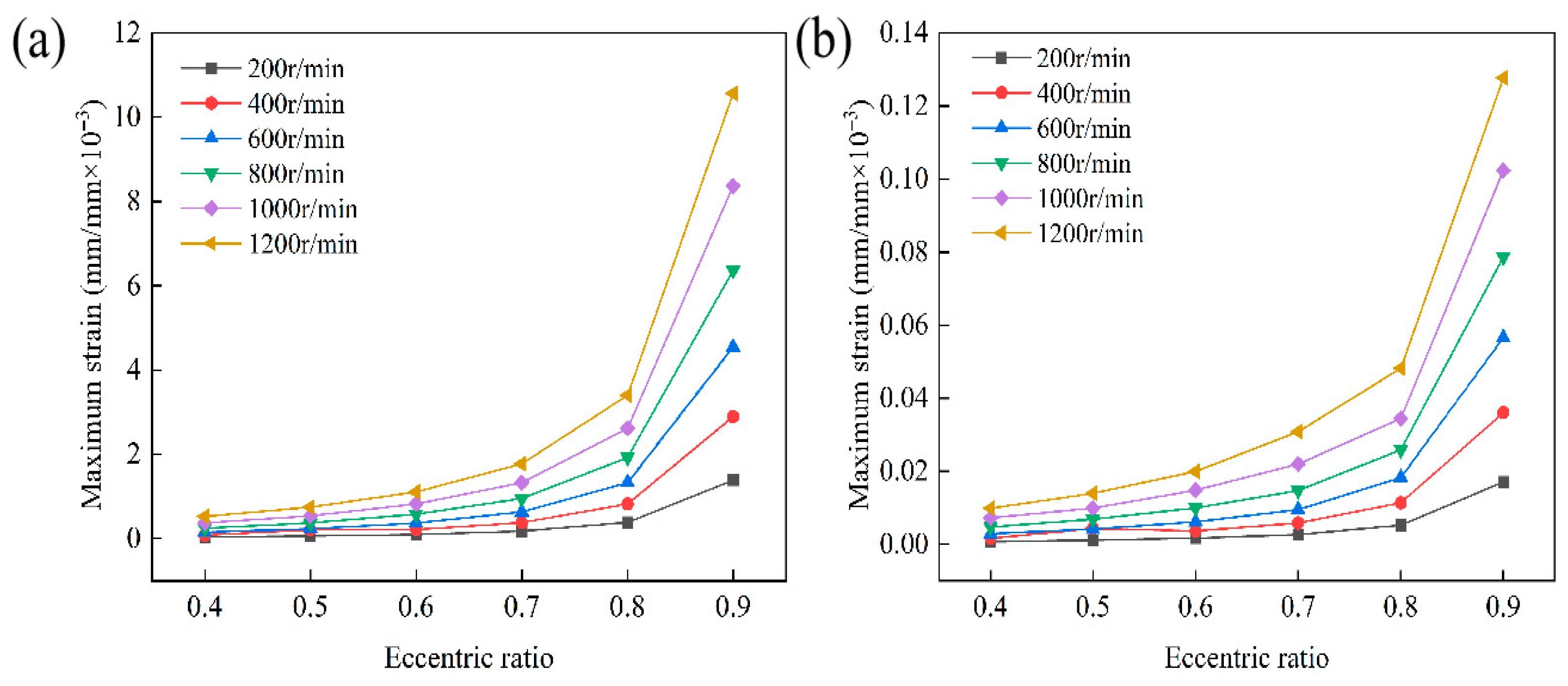
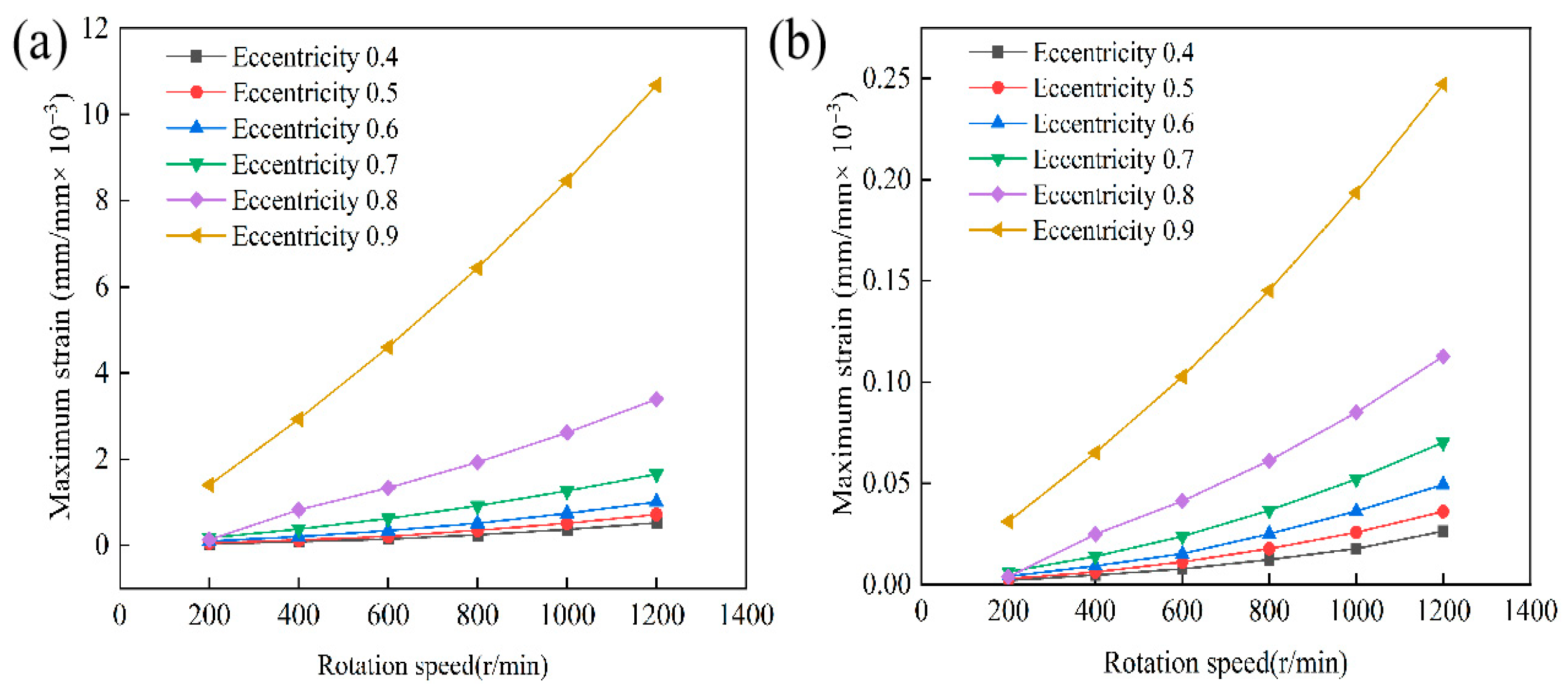
Figure 12 depicts the effect of eccentricity on the maximum strain experienced by Liner 1 and Liner 2 across different rotational speeds. The findings indicate that the maximum strain in both liners increases substantially with increasing eccentricity. A pronounced acceleration in the rate of growth occurs when eccentricity surpasses 0.8. This phenomenon is attributed to the reduction in minimum water film thickness associated with higher eccentricity. Higher eccentricity intensifies pressure concentration within the load-bearing region, resulting in greater material deformation. Under equivalent rotational speed and eccentricity conditions, the maximum strain in Liner 1 consistently exceeds that of Liner 2 by a significant margin. This disparity stems from differences in mechanical properties. Liner 1, characterized by a low elastic modulus and high compliance, undergoes considerable deformation under hydrodynamic pressure. Conversely, Liner 2, possessing a high elastic modulus and low compliance, exhibits minimal overall deformation and primarily functions as a rigid load-bearing layer. Moreover, increasing rotational speed amplifies the maximum strain in both liners. As the rotational speed increases, the hydrodynamic pressure intensifies, resulting in elevated peak pressures within the water film. This elevation results in a corresponding increase in linear deformation. Notably, Liner 1 demonstrates particularly pronounced strain growth under combined conditions of high speed and high eccentricity. This reflects its heightened sensitivity to variations in fluid pressure distribution. In contrast, Liner 2 shows a more moderate increase in strain, underscoring the inherent capacity of high-modulus materials to mitigate deformation under dynamic loading conditions.

4.2. Analysis of the Influence of Rotational Speed on the Lubrication Performance

Rotational speed is a critical parameter that strongly affects lubrication performance and load-carrying capacity in laminated water-lubricated bearings. In large-scale engineering systems, such as ship propulsion shafts, bearings operate over a range of varying rotational speeds. Changes in these speeds directly impact water film formation and system stability. It is therefore essential to study how speed affects maximum water film pressure, load capacity, frictional force, and frictional power dissipation. This investigation clarifies underlying mechanisms and supports structural optimization. Numerical simulations were conducted under representative conditions. Liner 1 was made of a rubber-based composite, and Liner 2 was made of UHMWPE. Both liners were 5 mm thick. Eccentricity was set at 0.5. Rotational speed varied from 200 to 1200 revolutions per minute. By comparing water film pressure, load capacity, frictional force, and power consumption at different speeds, this study reveals how speed influences fluid–structure interaction in laminated water-lubricated bearings. The results provide a theoretical basis for design optimization and engineering applications.
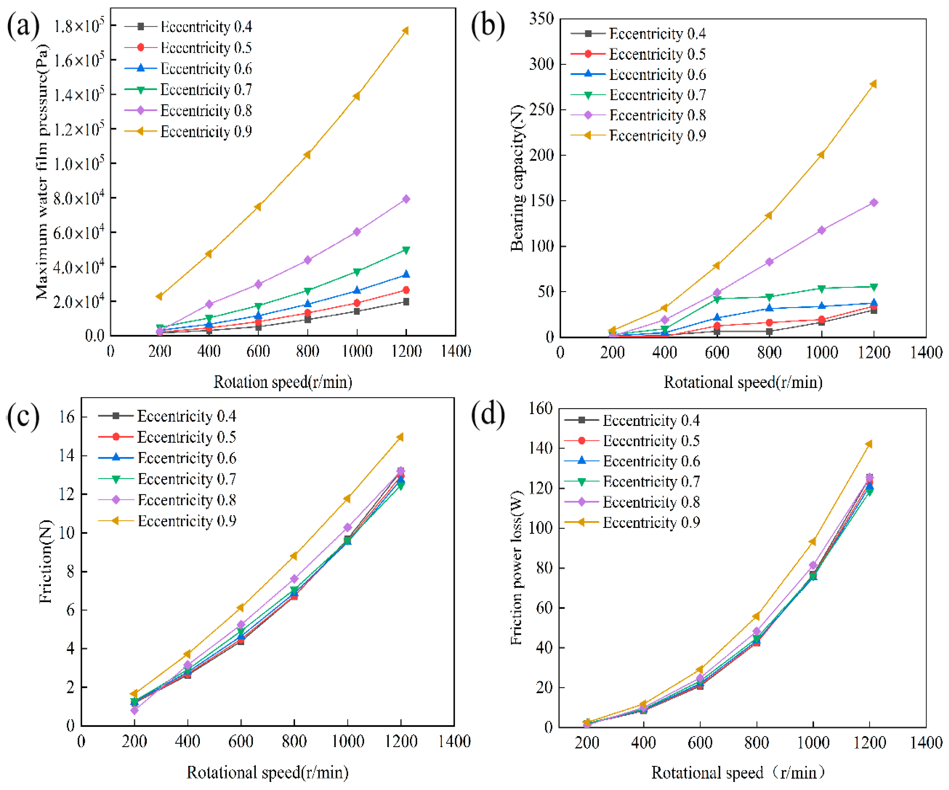
Figure 13 depicts the effect of rotational speed on the lubrication performance of a laminated water-lubricated bearing under various eccentricity conditions. As illustrated in Figure 13a, at a constant eccentricity, the maximum water film pressure increases progressively with rising rotational speed. Similarly, at a fixed rotational speed, the pressure significantly increases with greater eccentricity. When the eccentricity is below 0.8, the differences among the pressure curves are relatively minor. However, for eccentricities equal to or exceeding 0.8, the pressure curves exhibit a pronounced upward shift and accelerate with further increases in rotational speed. The highest pressure occurs at an eccentricity of 0.9. Figure 13b demonstrates that the load-carrying capacity increases with rotational speed; higher eccentricity at a constant speed further enhances this effect. This trend aligns with that of the maximum water film pressure. When eccentricity is at 0.8 or above, load-carrying capacity becomes much more sensitive to rotational speed. The curves then display a distinct upward curvature, which is most pronounced at an eccentricity of 0.9. Moving to Figure 13c, under constant eccentricity, the friction force increases approximately linearly with rotational speed. At a fixed speed, the friction force increases as the eccentricity increases, meaning that higher eccentricity corresponds to a greater friction force. Finally, Figure 13d shows that frictional power consumption increases with rotational speed at a constant eccentricity. At a fixed rotational speed, it also increases with eccentricity, reaching its peak at an eccentricity of 0.9.
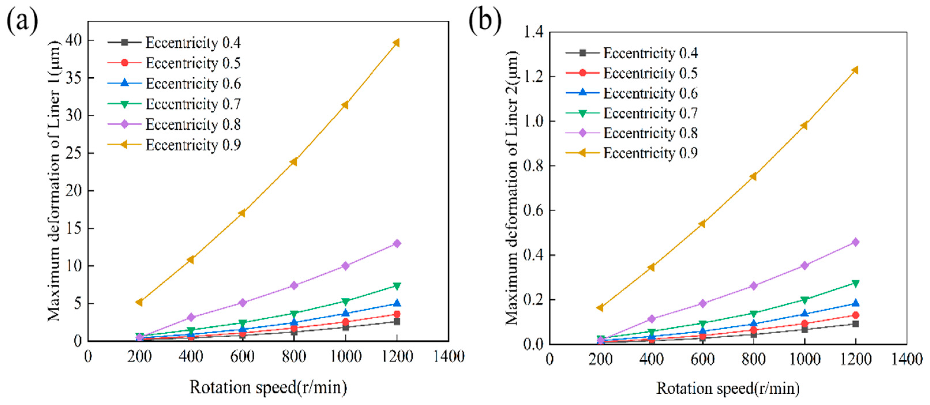
Figure 14a,b illustrate the maximum deformation behavior of Liner 1 and Liner 2 in a laminated water-lubricated bearing subjected to varying rotational speeds and eccentricities. The results indicate that the maximum deformation of both liners increases markedly with rising eccentricity at a constant rotational speed. Deformation also demonstrates a monotonically increasing trend with increasing rotational speed at a fixed eccentricity. However, significant differences are evident in both the magnitude and characteristics of deformation. For Liner 1, deformation increases approximately linearly with rotational speed at low eccentricities. It exhibits nonlinear, rapid growth when the eccentricity is greater than or equal to 0.9. For example, at an eccentricity of 0.9, deformation increases from 5.1823 μm at 200 r/min to 39.696 μm at 1200 r/min. This indicates that the combined effect of high eccentricity and high rotational speed substantially amplifies deformation amplitude under high-speed operating conditions. Conversely, the overall deformation of Liner 2 is significantly lower, approximately 1.5 to 2 orders of magnitude less than that of Liner 1. Although some deformation amplification occurs under combined high-speed and high-eccentricity conditions, it remains relatively low. This reflects strong resistance to structural deformation. These trends can primarily be attributed to the reduction in minimum water film thickness caused by increased eccentricity. This reduction intensifies local hydrodynamic pressure and elevates contact stress, thereby promoting material deformation. Increasing rotational speed further exacerbates this effect by raising tangential velocity and fluid pressure within the lubricant film. The rubber composite liner (Liner 1), owing to its high compliance and pronounced viscoelastic properties, exhibits more significant deformation amplification. In contrast, the UHMWPE liner (Liner 2) possesses higher stiffness and inherently lower deformation, although slight amplification may still occur under extreme loading conditions [36]. Therefore, in engineering design, eccentricity and rotational speed should be judiciously matched. Material selection and geometric parameters should also be optimized to achieve a balanced integration of load-carrying capacity, deformation resistance, and structural stability.
Figure 15 illustrates the variation in maximum equivalent stress for two liner materials within a laminated structure of water-lubricated bearings under different rotational speeds and eccentricities. The results indicate that the maximum equivalent stress increases as both rotational speed and eccentricity rise. However, there are notable differences in the magnitude and variation patterns between the two liners. In Figure 15a, the maximum equivalent stress of liner 1 rises monotonically with both increasing rotational speed and eccentricity. At an eccentricity of 0.4, the stress goes from 0.292 kPa at 200 r/min to 4.067 kPa at 1200 r/min, a 13.93-fold increase. At an eccentricity of 0.9, the stress jumps from 10.994 kPa to 83.693 kPa, a 7.61-fold increase. When the rotational speed is constant, the difference between high and low eccentricities is clear. The ratio of stresses is 37.66 at 200 r/min and 20.58 at 1200 r/min. This indicates that increasing eccentricity enhances the stress response to rotational speed, particularly at higher speeds. In Figure 15b, the maximum equivalent stress of liner 2 also rises with rotational speed and eccentricity and shows an almost linear relationship with speed. At an eccentricity of 0.4, the stress increases from 0.78967 kPa to 10.844 kPa, a 13.73-fold increase. At an eccentricity of 0.9, it rises from 18.542 kPa to 139.05 kPa, a 7.50-fold increase. At the same speed, the stress ratio for eccentricities 0.9 and 0.4 is 23.48 at 200 r/min and 12.82 at 1200 r/min. Compared to liner 1, liner 2 exhibits higher stress levels under the same conditions, but significantly less deformation. This reflects the high–stress, low-deformation behavior of high-modulus materials under concentrated loading. In summary, the interaction between eccentricity and rotational speed greatly affects stress distribution in water-lubricated bearings with a laminated structure. High eccentricity and high-speed operation can quickly increase stress levels, potentially compromising structural integrity. For this reason, engineering designs must carefully match eccentricity and rotational speed to ensure bearing reliability and stability.
Figure 16 demonstrates that, across all eccentricity conditions, the maximum strain in both liner types increases monotonically as the rotational speed rises from 200 r/min to 1200 r/min. This escalation is more pronounced in the higher speed range. Furthermore, at a fixed rotational speed, strain values increase with greater eccentricity. For liner 1, the most substantial strain amplification occurs at an eccentricity of 0.8. Here, the influence of eccentricity on strain is more significant at lower speeds and gradually diminishes as speed increases. Liner 2 exhibits a comparable trend. However, its overall strain magnitude is more than an order of magnitude lower than that of liner 1. Specifically, at an eccentricity of 0.9 and a rotational speed of 1200 r/min, the strain in liner 2 is approximately 1/43 that of liner 1. This indicates the considerable deformation-suppressing effect attributable to its higher elastic modulus and reduced viscoelastic damping. These observed trends can be explained by the reduction in minimum film thickness as eccentricity increases, along with the associated rise in hydrodynamic pressure. Higher rotational speeds further augment fluid dynamic pressure and shear stresses. The flexible rubber-based liner (liner 1) demonstrates greater sensitivity to strain development. In contrast, the stiffer liner two exhibits pronounced resistance to deformation. This underscores its superior structural rigidity under combined high-speed and high-eccentricity operating conditions.

4.3. Analysis of the Effect of Layer Thickness on Lubrication Performance

4.3.1. Analysis of the Effect of Layer 1 Thickness on Lubrication Performance

In laminated water-lubricated bearings, liner 1 consists of a rubber-based composite material. Its flexible deformation and viscoelastic properties are critical to the formation and stabilization of the hydrodynamic film. The thickness of liner 1 significantly influences the pressure gradient and the development of hydrodynamic pressure within the load-bearing region. It does so by modulating bearing compliance and contact stiffness. As a result, it affects key performance metrics, including water film pressure, load-carrying capacity, frictional force, and frictional power loss. Liner thickness also modifies stress transmission pathways and deformation patterns under fluid–structure interaction conditions. This process governs the spatial distribution of maximum deformation, stress, and strain. The existing literature lacks a systematic understanding of the effects of liner thickness. Therefore, this study performs a parametric comparative analysis at a fixed eccentricity ratio of 0.8 and a linear thickness of 2 mm. Liner 1 thicknesses are varied at 3, 5, 7, 9, 11, and 13 mm over a rotational speed range of 200 to 1000 r/min. The thickness-dependent response characteristics of the performance parameters are systematically examined. The underlying fluid–structure coupling mechanisms of the compliant liner in hydrodynamic lubrication are also elucidated. These findings provide a scientific basis for the optimal design of laminated water-lubricated bearings.
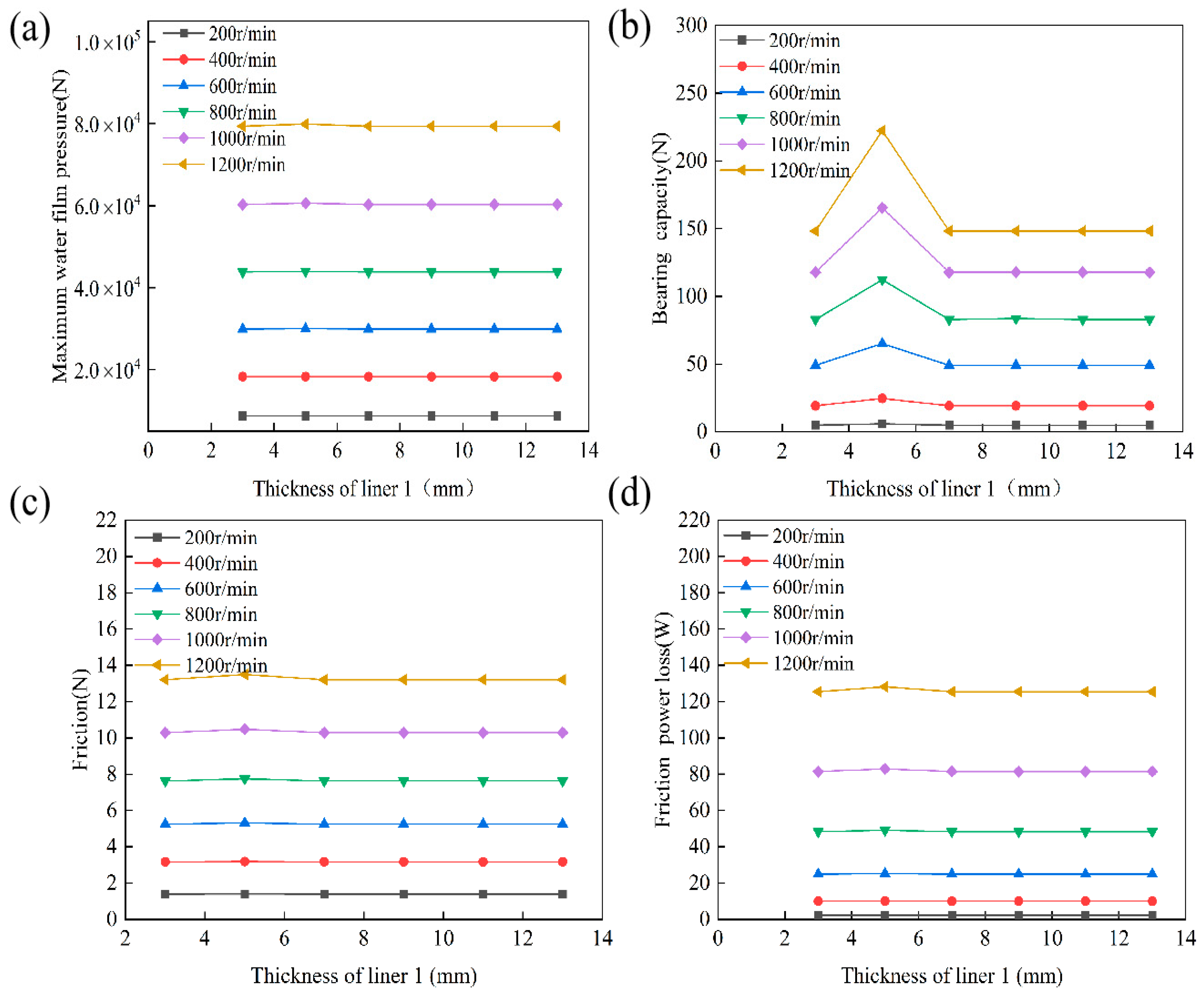
As shown in Figure 17a, the effect of liner 1 thickness on maximum hydrodynamic pressure is negligible. The fluctuation of maximum pressure at different speeds is extremely small across the 3–13 mm thickness range. The curves remain nearly horizontal, with relative variations of less than 1%. This occurs because, under fixed eccentricity, constant radial clearance, and constant water viscosity, variations in thickness do not significantly alter the film geometry. As a result, rotational speed has a significant influence on hydrodynamic pressure. This leads to a speed-dominated and thickness-insensitive characteristic [37]. Figure 17b demonstrates that the load-carrying capacity depends on both thickness and speed. For all speeds, the maximum load capacity occurs at a linear 1 thickness of 5 mm. For instance, at 1200 r/min, the load rises from 148.26 N to 222.28 N. This is a 50 percent increase. When the thickness exceeds 7 mm, the load capacity decreases sharply and then stabilizes. At a constant thickness, the load capacity increases monotonically with speed and grows more rapidly at higher speeds. For example, at a thickness of 5 mm, the load increases approximately 36.2 times as the speed rises from 200 r/min to 1200 r/min. This is due to the combined effects of stiffness and film geometry. At a thickness of 5 mm, compliance and viscoelasticity are optimally balanced. This forms a stable, wedge-shaped water film, enhancing hydrodynamic effects. By contrast, too little or too much thickness weakens this effect [38]. Figure 17c,d show that both the friction force and power loss are mainly governed by speed. Thickness has a negligible effect. At the same speed, changes in thickness cause less than 2.2 percent fluctuation in friction and power loss. Only a slight increase is observed at 5 mm. At a constant thickness, both the friction force and power loss increase as the speed rises. They exhibit convex growth at high speeds. For example, at a thickness of 5 mm, the friction force increases from 1.393 N to 13.492 N—a 9.69-fold increase. Power loss increases from 2.2047 W to 128.1770 W, representing a 58.1-fold rise. This is because friction results mainly from viscous shear stress in the water film. Both stress and power loss increase roughly in proportion to the square of the sliding velocity. Thickness changes have a limited effect on the flow field or velocity gradient. Only a slight increase occurs at 5 mm due to improved film geometry. In summary, the thickness of liner 1 has little effect on the maximum hydrodynamic pressure. However, there is a clear optimum thickness of about 5 mm for load-carrying performance. Its influence on friction and energy dissipation is minimal. These results suggest that the liner thickness in water-lubricated bearings should be optimized for optimal performance. It should balance load capacity, structural stiffness, and fatigue life for comprehensive performance improvement.
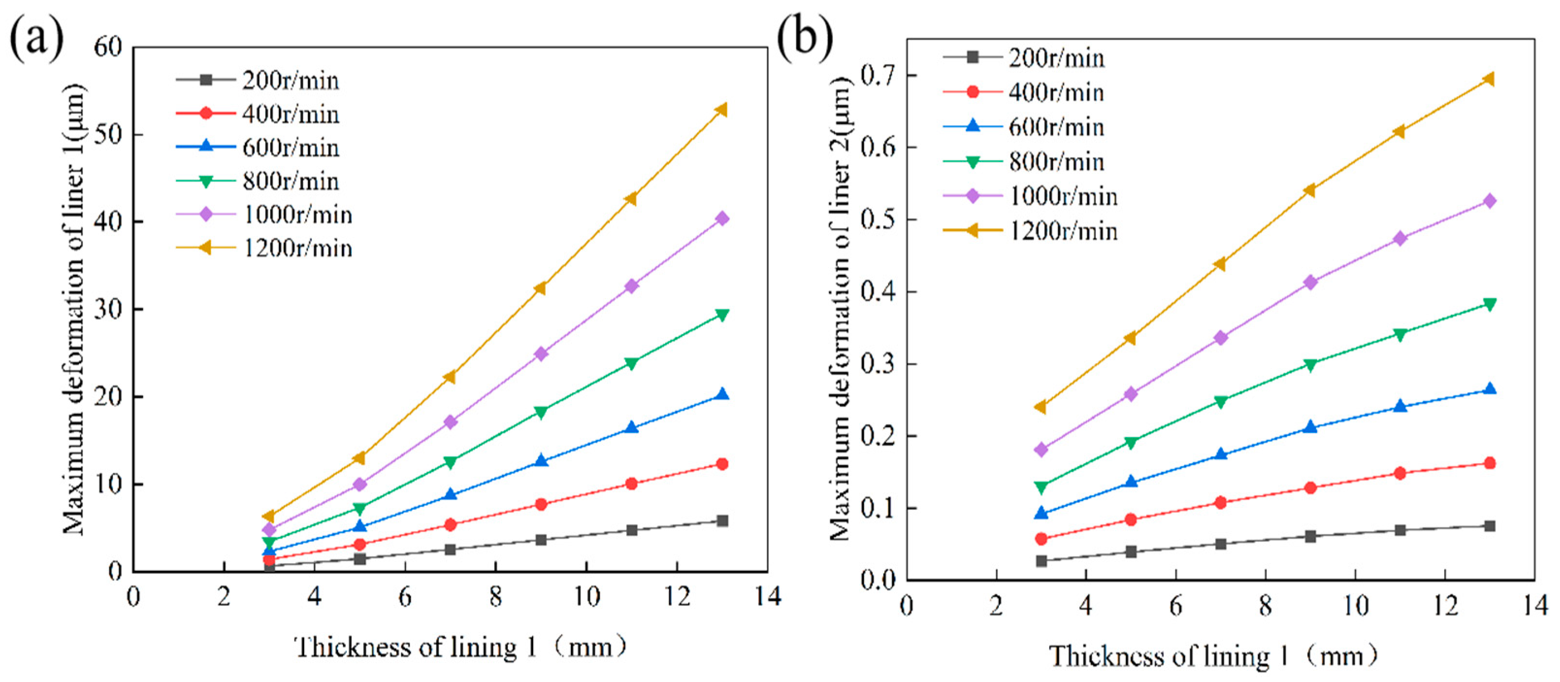
Figure 18 illustrates the significant impact of liner 1 thickness on the deformation behaviour of the double-layer liner structure. As shown in Figure 18a, within the 3–13 mm thickness range, the maximum deformation of liner 1 increases almost linearly with thickness. Sensitivity to thickness heightens at elevated rotational speeds. For every 1 mm increase in thickness, deformation increases from approximately 0.523 μm at 200 r/min to approximately 4.738 μm at 1200 r/min. This represents a ninefold increase. At constant thickness, deformation increases markedly with speed. For a 3 mm liner, maximum deformation rises from 0.6539 μm to 6.3362 μm. For a 13 mm liner, the diameter ranges from 5.8038 μm to 52.834 μm. This occurs due to hydrodynamic pressure and viscous shear, which intensify with speed and elevate interfacial stress. Increased liner thickness boosts structural compliance and amplifies hysteresis energy dissipation in the rubber. Also, localized temperature rises at high speeds may reduce the rubber’s elastic modulus and promote more deformation. These factors combine in a nonlinear, multi-physics coupling mechanism to amplify deformation response. Figure 18b shows that the maximum deformation of liner 2 also grows with liner 1 thickness and rotational speed, but much less so. Each 1 mm increase in liner 1 thickness increases the deformation of liner 2 by about 0.00495 μm at 200 r/min, and by 0.04623 μm at 1200 r/min. With liner 1 thickness increasing from 3 mm to 13 mm, the total deformation increment of liner 2 across speeds ranges from 0.04914 μm to 0.45493 μm. This is because hydrodynamic pressure and viscous shear from the water film are mostly absorbed by the more compliant liner 1, which then transmits elastic deformation to the stiffer liner 2. This results in a subordinate or ‘following’ deformation of liner 2. However, liner 2’s higher elastic modulus and rigidity constrain its deformation response. In summary, the maximum deformations of both liners rise with the thickness of liner 1 and the rotational speed. Liner 1 shows much greater deformation magnitude and sensitivity to these parameters than liner 2. This study reveals the coupled amplification effect of liner thickness on deformation in laminated water-lubricated bearings. It highlights the importance of optimal design that considers how liner thickness affects load-carrying capacity, deformation control, and damping/vibration isolation, to achieve balanced and improved system function.
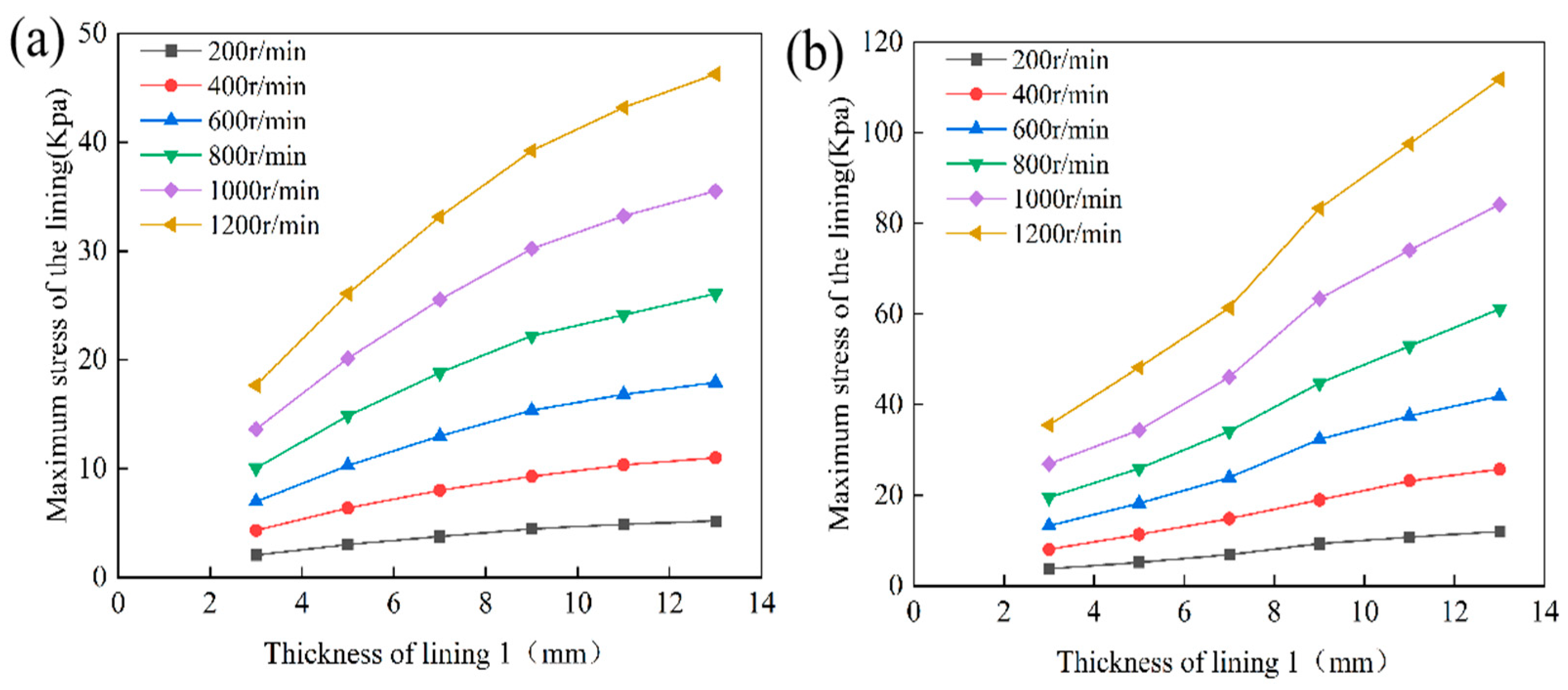
Figure 19a,b illustrate the effect of liner 1 thickness on the maximum equivalent stress in both liner 1 and liner 2. Within the thickness range of 3 to 13 mm, the maximum stress in both liners increases monotonically with thickness. This stress is significantly amplified as the rotational speed rises. For liner 1 at a rotational speed of 1200 r/min, increasing the thickness from 3 mm to 13 mm raises the maximum stress from 17.642 kPa to 46.256 kPa. The increment in stress per 2 mm increase in thickness gradually decreases, indicating a diminishing sensitivity to thickness. At higher rotational speeds, the stress increase for equivalent thickness increments is substantially greater. This demonstrates that the effect of thickness variation on stress amplification intensifies as speed increases. For liner 2, when the thickness rises from 3 mm to 13 mm, the maximum stress increment across all speeds ranges from 8.238 kPa to 76.292 kPa. This trend is consistent with that observed for liner 1. Notably, at 1200 r/min, the stress increases by 21.934 kPa when the thickness rises from 7 mm to 9 mm. This interval is a region of heightened stress sensitivity. At constant thickness, the maximum stress in both liners increases approximately superlinearly with rotational speed. For example, at a thickness of 3 mm, the maximum stress in liner 1 and liner 2 increases from 0.6539 kPa and 3.7533 kPa at 200 r/min to 6.3362 kPa and 35.478 kPa at 1200 r/min, respectively. This represents an approximate ninefold increase. Overall, under identical operating conditions, liner 2 exhibits higher absolute stress levels and greater sensitivity to thickness variations than liner 1. It particularly demonstrates more pronounced stress concentration in the medium-thickness range and at elevated rotational speeds. These findings emphasise the importance of comprehensively considering the interactions among liner thickness, rotational speed, and material properties in the design of laminated water-lubricated bearings. This approach helps to optimise the balance among load-carrying capacity, deformation control, and stress safety margins.
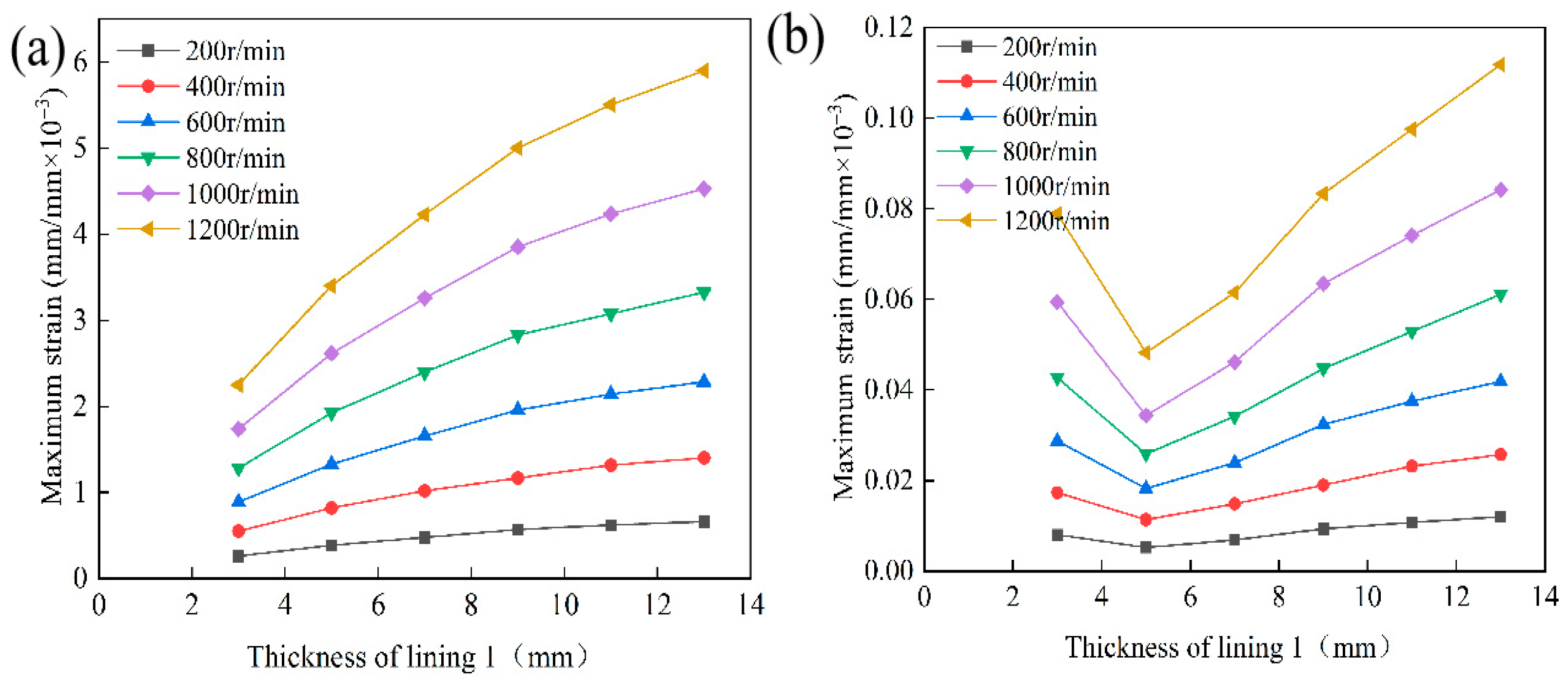
Figure 20 illustrates the effect of the thickness of liner 1 on the maximum equivalent elastic strain within a double-layer liner structure subjected to varying rotational speeds. As depicted in Figure 20a, over the thickness range of 3 to 13 mm, the maximum equivalent strain in liner 1 increases monotonically with thickness. This increase is approximately linear overall. Furthermore, the sensitivity of strain to thickness becomes significantly more pronounced as rotational speed increases. For instance, at 1200 r/min, increasing the thickness from 3 mm to 13 mm results in the strain rising from 2.2503 × 10⁻³ to 5.9000 × 10⁻³. Under constant thickness conditions, the strain also increases markedly with rotational speed. The amplification occurs by factors of 8.62 and 8.82 for thicknesses of 3 mm and 13 mm, respectively. This indicates a substantial amplification effect due to the interaction between thickness and rotational speed. Figure 20b demonstrates that the maximum equivalent strain in liner 2 exhibits a non-monotonic relationship with the thickness of liner 1. The strain initially decreases and then increases, with a minimum observed at approximately 5 mm. At 1200 r/min, increasing the thickness from 3 mm to 5 mm reduces the strain from 0.07884 × 10⁻³ to 0.04521 × 10⁻³, corresponding to a 42.7% decrease in strain. Further increasing the thickness to 13 mm causes the strain to rise to 0.11177 × 10⁻³, which is 147.2% higher than the value at 5 mm. This pattern is consistent across all examined rotational speeds, with greater sensitivity to thickness observed at higher speeds. Under fixed thickness conditions, the strain in liner 2 increases with rotational speed, following a slightly superlinear trend. Amplification factors of 9.83 and 9.32 are seen for thicknesses of 3 mm and 13 mm, respectively. A comparative analysis reveals that the strain magnitude in liner 1 is substantially greater than that in liner 2. The strain in liner 1 increases consistently with both thickness and rotational speed. In contrast, liner 2 exhibits a distinct optimal thickness range near 5 mm. Here, the buffering capacity of liner 1 and the uniformity of the water film pressure distribution are optimally balanced, thereby minimising strain in liner 2. When liner 1 is skinny, load transfer to liner 2 intensifies. This transfer results in elevated strain levels. Conversely, when liner 1 is overly thick, increased compliance diminishes structural constraint and leads to amplified follower deformation. At elevated rotational speeds, this effect is further exacerbated by hysteresis energy dissipation and localised temperature increases. Together, these factors contribute to a significant rise in strain within liner 2. These findings underscore the necessity of considering operational speed and loading conditions in designing laminated water-lubricated bearings. They also emphasise the importance of rationally selecting liner 1 thickness to optimise strain management and load-carrying performance.

4.3.2. Analysis of the Effect of Layer 2 Thickness on Lubrication Performance

In laminated water-lubricated bearings, the thickness of liner 2 significantly affects the stiffness of the bearing and its compatibility with liner 1. Changing this thickness also alters important structural and frictional properties, including the amount of load the bearing can support, the degree of surface pressure, and the stability of the fluid film. These changes affect key performance measures, including the bearing’s capacity to carry weight, the amount of friction it generates, and the power loss it incurs. When both fluid and solid parts interact, changes in liner 2 thickness also affect how stress moves through the layers and how the bearing bends or deforms. Although this factor is important, few studies have examined how liner 2 thickness affects bearing performance. This study addresses this gap by testing six different liner 2 thicknesses, all at the same eccentricity ratio of 0.8, and comparing them as the rotation speed goes from 200 to 1000 r/min. The goal is to better understand how linear 2 thickness changes affect lubrication and mechanics, to help design better bearings.
Figure 21 illustrates that, at an eccentricity of 0.8 and a liner 1 thickness of 5 mm, variations in liner 2 thickness exert a limited overall effect on the lubrication performance of the laminated water-lubricated bearing. However, certain trends emerge under specific operating conditions. As depicted in Figure 21a, within the rotational speed range of 200 to 1200 r/min and for liner thicknesses between 3 and 13 mm, the maximum water film pressure remains stable across all tested configurations, with minimal variation due to thickness changes. At speeds exceeding 600 r/min, pressure fluctuations attributable to thickness changes are less than 0.63%, with only minor localised deviations observed at lower speeds. In contrast, the impact of rotational speed is substantially more significant: the maximum water film pressure at 1200 r/min is approximately 9.13 times greater than that at 200 r/min, indicating that hydrodynamic lubrication is predominantly governed by rotational speed, whereas the influence of liner 2 thickness is constrained by its relatively high stiffness. Figure 21b demonstrates that the effect of liner 2 thickness on load-carrying capacity is generally weak; however, a distinct peak in performance occurs at a thickness of 5 mm. Compared to the 3 mm configuration, the load-carrying capacity increases by 22.3% to 49.9% across different speeds when the liner 2 thickness is 5 mm. When the liner thickness exceeds 7 mm, the load-carrying capacity decreases and reaches levels comparable to those at 3 mm. At any given thickness, steadily increasing the rotational speed increases load support. The improvement at 5 mm comes from an optimal stiffness match between liner 2 and the flexible surface of liner 1. This helps distribute pressure more evenly and keeps the hydrodynamic wedge more stable, thereby boosting load support. Figure 21c,d show that the thickness of liner 2 has a negligible effect on the friction force or power consumption. Above 600 r/min, friction changes due to thickness remain under 2%, and power usage is almost unchanged, except for a small shift at 200 r/min with a 7 mm thickness. At a fixed thickness, friction rises quickly as speed increases, exhibiting “speed-dominant” behavior. For example, at 5 mm, friction grows by 9.83 times as the speed rises from 200 to 1200 r/min. Across thicknesses ranging from 3 to 13 mm, liner 2 has a limited effect on the wedge flow and cannot significantly alter the water film flow, resulting in minimal improvement in friction force and power usage.
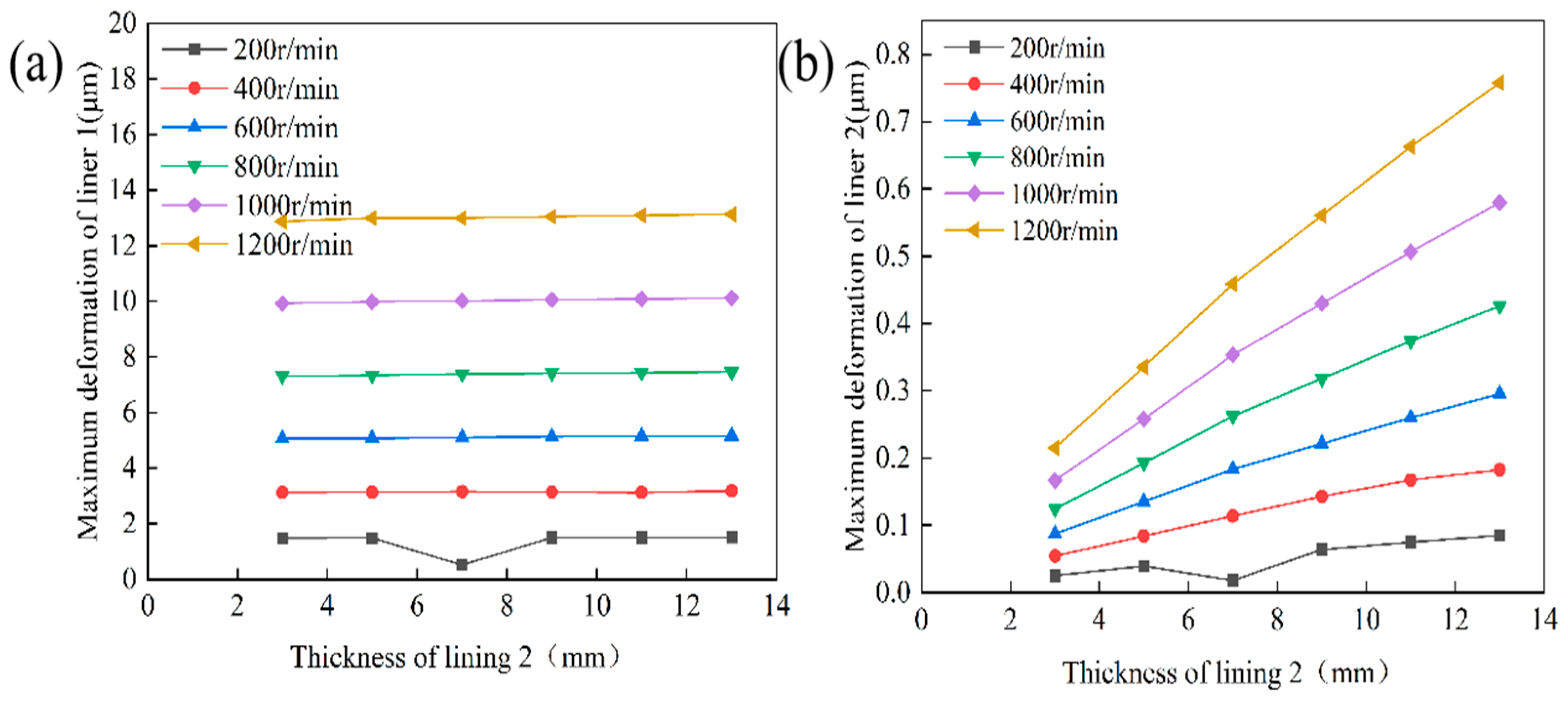
Figure 22a,b depict the effect of variations in the thickness of liner 2 on the maximum deformation of both liner 1 and liner 2. The conditions are an eccentricity of 0.8 and a fixed linear 1 thickness of 5 mm. The findings reveal that the maximum deformation of liner 1 is minimally affected by changes in the thickness of liner 2. At 800 r/min, the deformation of liner 1 rises only slightly from 7.3203 μm at 3 mm liner 2 thickness to 7.4566 μm at 13 mm. This change reflects a 1.86% increase. At 1200 r/min, the increase is 3.58%. In contrast, rotational speed has a much greater impact. When the liner 2 thickness is held at 5 mm, the maximum deformation of liner 1 increases from 1.14818 μm at 200 r/min to 12.985 μm at 1200 r/min. This change represents an 8.76-fold increase. At 200 r/min, a local minimum in linear 2 deformation is observed at a thickness of 7 mm. This may result from incomplete development of hydrodynamic pressure effects at low speeds. Maximum deformation of liner 2 is highly sensitive to both thickness and speed. At 800 r/min, liner 2 deformation rises from 0.12451 μm at 3 mm to 0.42604 μm at 13 mm—a 242.2% increase. At 1200 r/min, the increase is 252.6%. Under constant thickness, liner 2’s maximum deformation increases by a factor of 8.5 to 8.9 as rotational speed rises from 200 to 1200 r/min. Despite substantial relative deformation, liner 2 still displays significantly lower absolute deformation than liner 1. This is due to its higher structural stiffness, which limits its contribution to overall system deformation. In summary, within the examined thickness range, the deformation of liner 1 is primarily governed by material properties and rotational speed. In contrast, liner 2 responds to variations in thickness and speed, while maintaining low absolute deformation and minimal influence on the total system deformation.
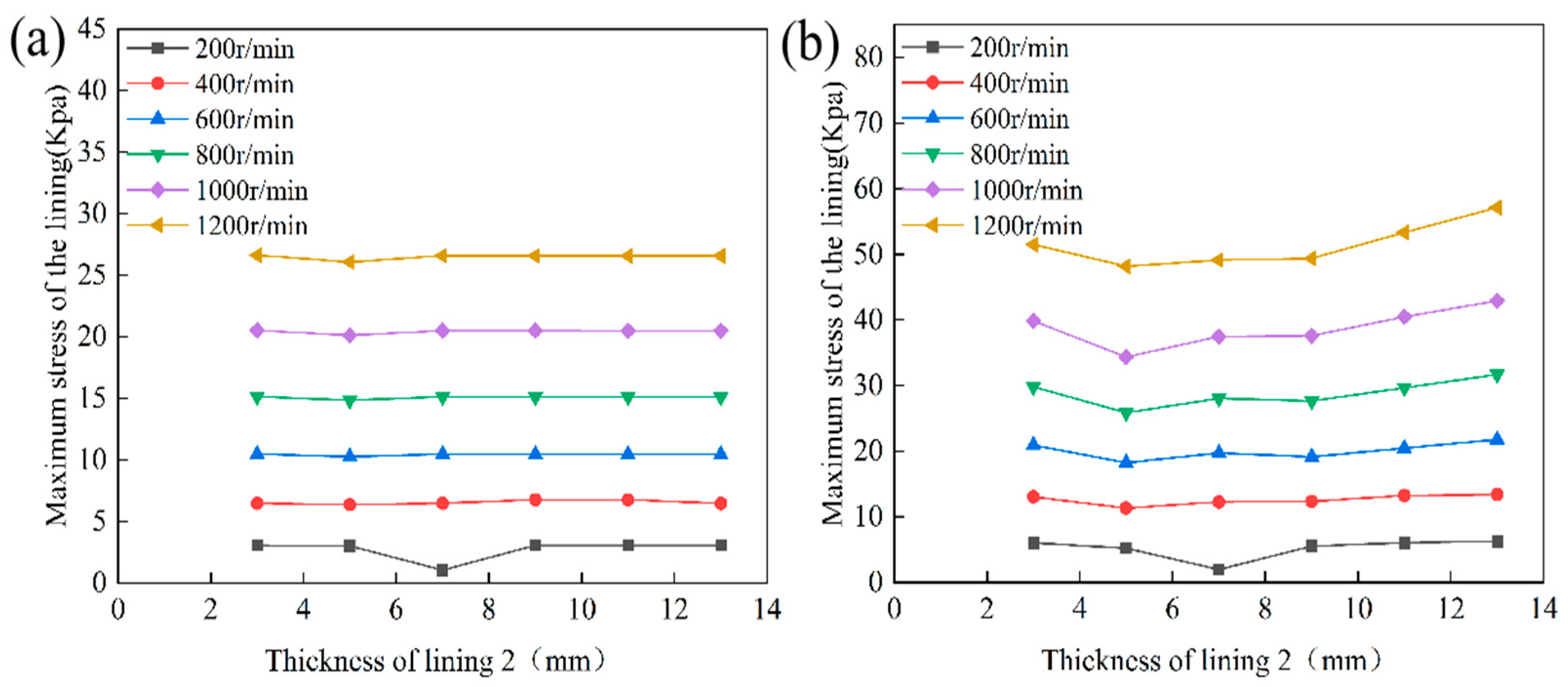
Figure 23 presents the effect of varying the thickness of liner 2, ranging from 3 to 13 mm, on the maximum equivalent stress experienced by both liner 1 and liner 2. This analysis is conducted under an eccentricity of 0.8 and a fixed liner 1 thickness of 5 mm. Rotational speeds span from 200 to 1200 r/min. As illustrated in Figure 23a, the maximum stress in liner 1 shows minimal sensitivity to changes in liner 2 thickness. The trend remains nearly flat throughout the examined range. Specifically, at rotational speeds of 600, 800, 1000, and 1200 r/min, stress variations attributable to thickness changes remain below 0.3%. At 400 r/min, the relative change reaches 6.07%, but the absolute variation remains negligible. In contrast, rotational speed exerts a much greater influence. For a liner 2 thickness of 5 mm, the maximum stress in liner 1 increases from 3.017 kPa at 200 r/min to 26.077 kPa at 1200 r/min, representing a 7.64-fold increase. This phenomenon can be explained by the much lower elastic modulus of liner 1 compared to the UHMWPE backing. As a result, stress distribution is mainly governed by the rubber’s mechanical properties and the hydrodynamic pressure field. Within the investigated thickness range, changes in backing stiffness do not significantly affect the peak stress in the rubber layer. In contrast, increasing rotational speed directly amplifies hydrodynamic pressure, markedly increasing stress levels. Figure 23b shows that the maximum stress in liner 2 also increases significantly with rotational speed, confirming that speed is the dominant influencing factor. At a thickness of 5 mm, the stress rises from 5.211 kPa at 200 r/min to 48.186 kPa at 1200 r/min, corresponding to a 9.25-fold increase. Across all thicknesses, amplification factors consistently range between 8.6 and 9.3. Unlike liner 1, the maximum stress in liner 2 shows a distinct U-shaped dependence on thickness, with a minimum in the 5–7 mm range. When the thickness increases to 11–13 mm, the stress rises by 18% to 25% relative to the minimum value. This trend can be attributed to the following mechanism: At small thicknesses, the backing lacks sufficient bending stiffness, resulting in high bending stresses. Moderate increases in thickness enhance global stiffness and reduce stress. However, excessive thickness reduces compliance, increases the load transferred to the backing, and intensifies shear lag effects, leading to a subsequent increase in stress. In summary, the maximum stress in liner 1 is largely insensitive to variations in liner 2 thickness, whereas liner 2 exhibits an optimal thickness range of about 5–7 mm for minimizing peak stress. Both layers experience significant stress increases as rotational speed rises, with comparable magnitudes of growth. From an engineering design perspective, reducing stress in the rubber layer should focus on highly sensitive parameters such as rotational speed, eccentricity, liner 1 thickness, and material properties. To minimize stress in the UHMWPE backing, the thickness of liner 2 should be controlled within the 5–7 mm range for optimal stress reduction [39,40].
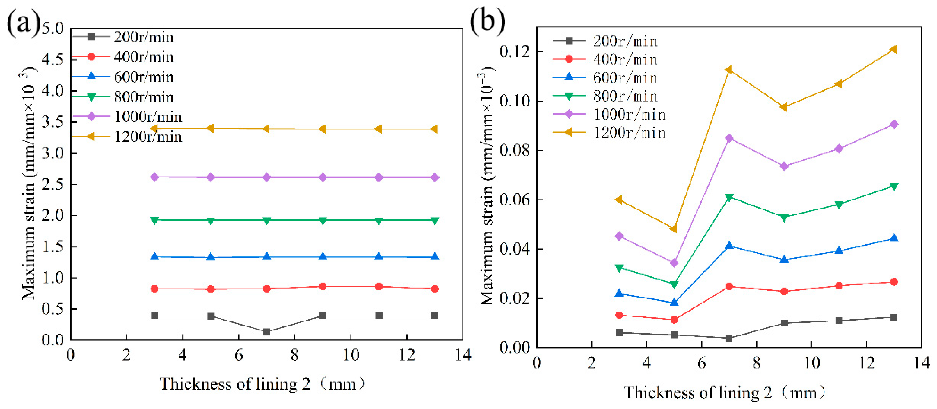
Figure 24 depicts the effect of variations in liner 2 thickness on the maximum strain experienced by both liner 1 and liner 2 under different rotational speeds, with an eccentricity of 0.8 and a constant liner 1 thickness of 5 mm. The findings reveal that the maximum strain in liner 1 is minimally affected by changes in the thickness of liner 2 but is highly dependent on the rotational speed. Specifically, at a liner 2 thickness of 5 mm, the strain in liner 1 increases by a factor of 8.79 as the rotational speed increases from 200 to 1200 r/min. This phenomenon is attributed to the relatively low elastic modulus of liner 1; variations in the thickness of liner 2 produce only minor alterations in the system’s base stiffness, resulting in negligible effects on the strain distribution. Instead, the strain evolution in liner 1 is predominantly influenced by hydrodynamic pressure. Conversely, the maximum strain in liner 2 increases substantially with rotational speed—by factors of 9.25 at 5 mm thickness and up to 9.79 at 13 mm thickness—and exhibits marked sensitivity to thickness variation, displaying a distinct optimal range. Within the rotational speed range of 400 to 1200 r/min, the minimum strain at each operating condition occurs at approximately 5 mm thickness. Strain levels remain low within the 5–7 mm thickness interval but increase significantly when the thickness reaches 11–13 mm. This behavior can be explained as follows: moderate thickening of the UHMWPE layer enhances overall structural stiffness and reduces internal strain; however, excessive thickness reduces structural compliance, increases load transfer to the backing layer, and intensifies shear lag effects, thereby causing a rebound in strain. In summary, strain variation in liner 1 is primarily governed by rotational speed and eccentricity, with negligible influence from liner 2 thickness. In contrast, strain in liner 2 is susceptible to thickness changes, with an optimal range identified between 5 and 7 mm. From an engineering design perspective, mitigating strain in liner 1 should focus on adjusting operational parameters, such as rotational speed and eccentricity. For liner 2, optimizing thickness within the 5–7 mm range is recommended to minimize strain and improve service performance.

4.4. Experimental Validation of Laminated Water-Lubricated Bearing Specimens

4.4.1. Experimental Materials and Equipment
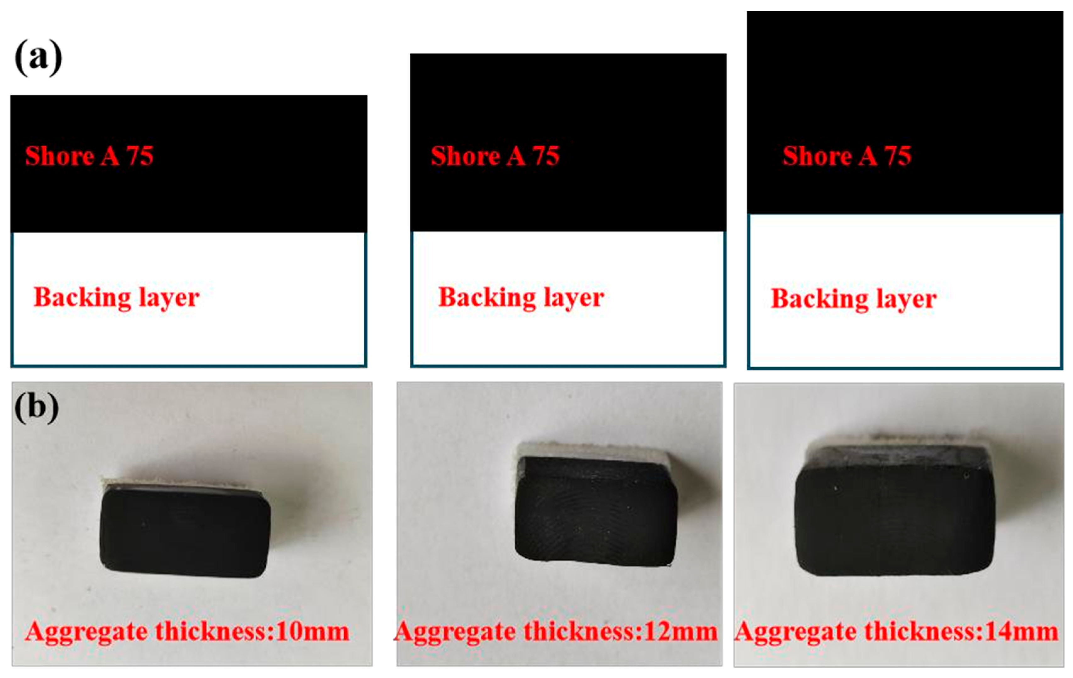
The surface layer Liner 1 was a rubber-based composite of nitrile butadiene rubber, UHMWPE, solid lubricants, and additives. It was prepared by melt blending, compression molding, and vulcanization using a hydraulic hot press. Hardness was adjusted by varying the ratios of carbon black and curing agent, while thickness depended on the mold cavity size. Specimens had a Shore A hardness of 75 and nominal dimensions of 15.5 mm × 6.5 mm, with thicknesses of 5 mm, 7 mm, and 9 mm. Meanwhile, the backing layer Liner 2 was made from UHMWPE supplied by Shandong Ningjin Mingyang New Materials Co., Ltd. (Dezhou City, China). It was machined into 15.5 mm × 6.5 mm × 5 mm blocks using a CNC lathe. Following this, a two-part epoxy adhesive was applied after surface activation, and the layers were bonded together under heat and pressure. As a result, the resulting laminates had total thicknesses of 10 mm, 12 mm, and 14 mm, corresponding to surface layer thicknesses of 5 mm, 7 mm, and 9 mm, respectively. Finally, the counter-body material used in the tests was a tin bronze alloy, ZCuSn10Zn2. Figure 25 illustrates the specimen configuration.
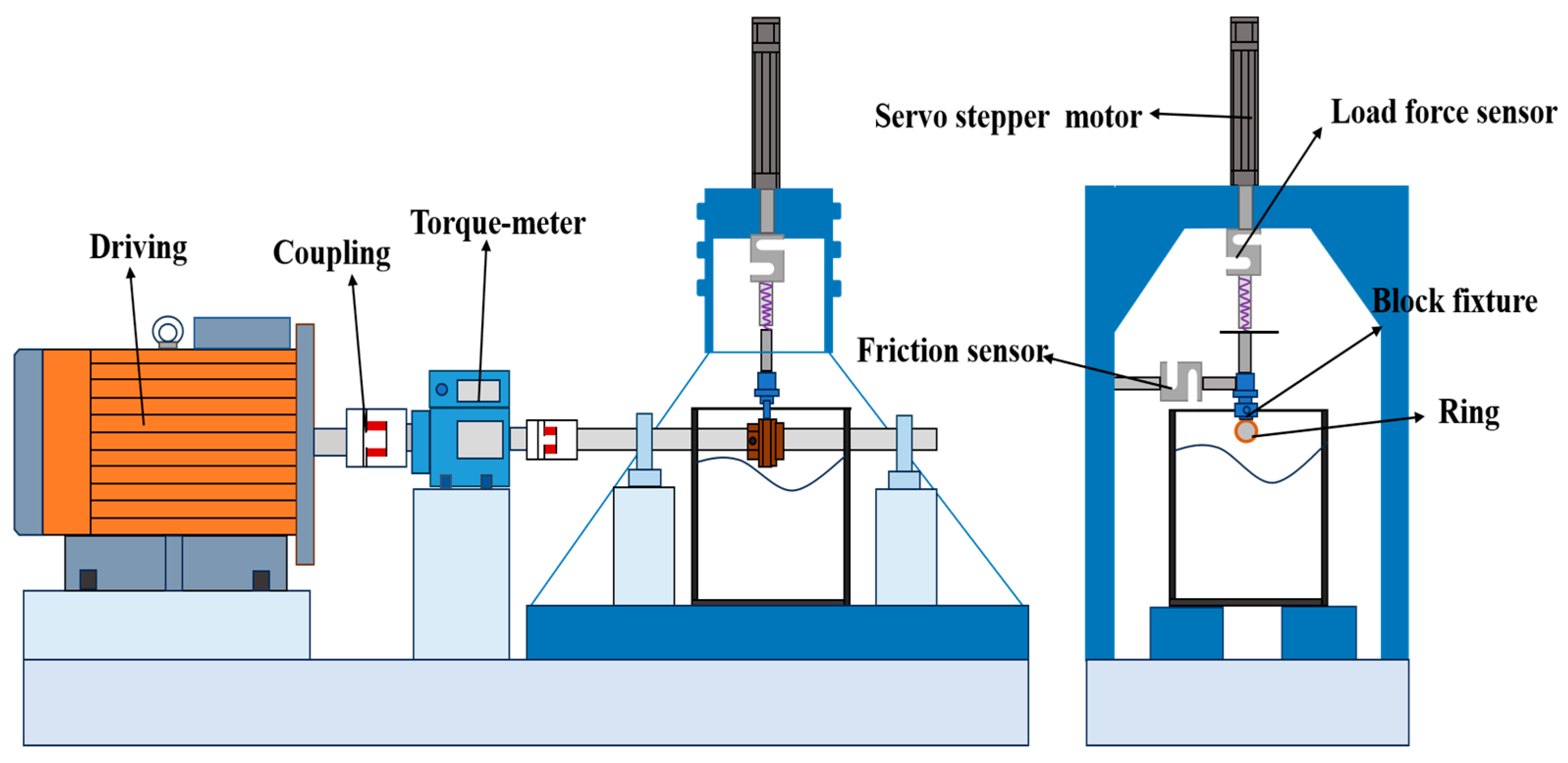
Friction performance tests were conducted using a custom-designed ring-on-block tribometer, which was independently developed at Wuhan University of Technology. The apparatus consists of five primary subsystems: a drive system, a transmission system, a loading system, a test module, and a lubrication system. Figure 26 presents a schematic illustration of the ring-block friction and wear testing machine. The drive motor operates at a maximum speed of 1440 r/min, transmitting rotational motion to the test shaft via a coupling. Rotational speed and torque are continuously monitored by dedicated sensors integrated within the shaft assembly. The normal load is applied through a servo-driven stepping motor, combined with a preload spring mechanism. Both the applied normal force and the resulting friction force are measured in real-time using a high-precision pressure sensor. The test configuration involves a copper alloy ring paired with a laminated specimen in a standard ring-on-block contact arrangement. The lubrication system ensures complete immersion of the friction pair in deionized water through a sealed reservoir equipped with watertight sealing components. Both the normal load and friction force sensors have a measurement range of 0 to 300 N. A Donghua dynamic data acquisition system synchronously acquires all experimental signals, which are subsequently amplified and filtered before being transmitted to the DHDAS platform for real-time processing, analysis, and storage.
Figure 26. Schematic diagram of the ring-on-block friction and wear testing machine structure.
Lubricants 13 00445 g026

4.4.2. Analysis of Test Results

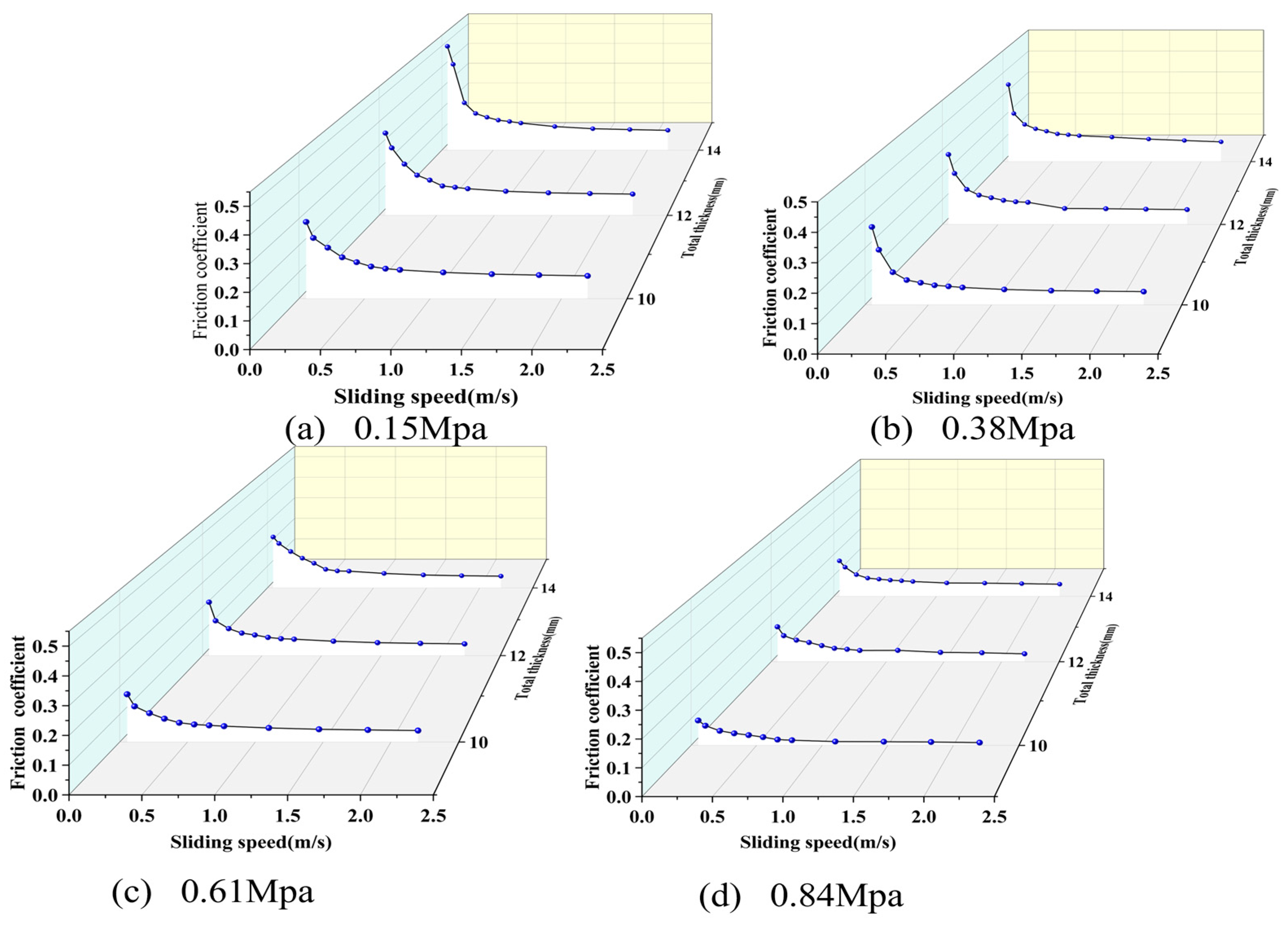
Friction performance tests on laminated water-lubricated bearings were conducted in accordance with the U.S. Navy standard MIL-DTL-17901C SH [41] and the Chinese shipbuilding industry standard CB/T 769–2008 [42]. These tests aimed to evaluate bearing deformation behavior under operational conditions. The experimental parameters included nine rotational speeds, ranging from 30 to 1200 r/min, and four normal load levels: 10 N, 25 N, 40 N, and 55 N. These corresponded to nominal contact pressures of 0.15 MPa, 0.38 MPa, 0.61 MPa, and 0.84 MPa, respectively. Each test condition included a 30 min running-in phase. This was followed by three repeated 6 min steady-state cycles at the specified speed to ensure data reliability and repeatability. Before testing, the specimens and ZCuSn10Zn2 copper rings were polished using progressively finer abrasive papers. Surface characterization was performed with a laser interferometric surface profilometer, and the average surface roughness (Ra) was 0.8 μm. All samples were then cleaned with deionized water and dried in an oven at 60 °C for 12 h. A fresh friction pair was used in each test to prevent cross-contamination and rule out the influence of wear history. During the experiments, normal load and friction torque were continuously monitored via tribometer sensors. The coefficient of friction was calculated accordingly.
Figure 27 shows how the friction of water-lubricated bearing samples with a Shore A hardness of 75 changes with different thicknesses. The results show that the thickness of the sample significantly affects the amount of friction, even when speed and load remain constant. As the thickness decreases, the friction also decreases, showing a clear connection. At low speeds, the parts mainly slide against each other, causing higher friction that increases as the sample gets thicker. At medium speeds between 0.33 m/s and 1.1 m/s, a water layer forms and cushions the contact, but it is not yet a complete film. Thicker samples still have slightly higher friction in this situation. These results demonstrate that thickness influences the interaction between surfaces and the ease with which parts slide past each other, making it an important consideration when designing water-lubricated bearings. Comparing predictions with test results also supports the reliability of the model for bearing performance.

4.5. Analysis of Energy Dissipation Mechanism in Layered Structure Hydro-Lubricated Bearings

In laminated water-lubricated bearings, energy transmission and dissipation occur in three stages—fluid damping, viscoelastic damping in the flexible rubber liner, and structural damping in the backing layer. Figure 28 illustrates this sequence. Under hydrodynamic pressure, the fluid film carries the primary load. It converts part of the mechanical input into heat through viscous shear, which the lubricant flow removes. The undissipated energy is transferred to the flexible liner, Liner 1, where molecular chain friction and stress–strain hysteresis, both characteristic of viscoelastic materials, further attenuate it. Remaining energy passes to the backing liner, Liner 2. Here, secondary dissipation happens through structural damping. External operating conditions mainly govern the energy input. Increasing eccentricity reduces the minimum film thickness and elevates the peak hydrodynamic pressure. This intensifies the energy influx. Increasing rotational speed causes a steady rise in film pressure and frictional power. At high speeds, this rise shows a convex trend and markedly enhances overall system dissipation.
Based on the aforementioned energy dissipation pathway, Liner 1 plays a predominant role in energy dissipation. Its thickness directly modulates system compliance. It governs the development of wedge-shaped hydrodynamic pressure. As a result, Liner 1 influences the multi-objective trade-off among load-carrying capacity, energy dissipation, and structural deformation. An optimal thickness for Liner 1—approximately 5 mm—enables a favorable balance between load-bearing performance and energy dissipation efficiency. Although increased thickness enhances viscoelastic damping, it also elevates maximum deformation and equivalent strain. This results in localized stress concentration. Conversely, insufficient thickness diminishes both the effectiveness of energy dissipation and the load-carrying capacity. In contrast, Liner 2 primarily provides rigid support and contributes to secondary energy dissipation. Its thickness affects the overall system response by adjusting global stiffness and redistributing interfacial loads. A thickness range of 5 to 7 mm allows Liner 2 to achieve high energy attenuation efficiency and minimize structural response. Thicknesses below this range may lead to inadequate stiffness and stress localization. Excessive thickness reduces system compliance, causing rebound effects in stress and strain levels. The two Liners form a synergistic mechanism through thickness-dependent interactions. Liner 1 governs viscoelastic damping and deformation accommodation. Liner 2 ensures structural integrity and facilitates additional energy dissipation. This interaction enables hierarchical energy transfer and staged attenuation along the “fluid–flexible Liner–backing” pathway. It provides a theoretical foundation for coordinated optimization of load-carrying capacity, energy dissipation efficiency, and structural safety margin.

5. Conclusions

This study examines the common challenges associated with conventional water-lubricated bearings, such as vulnerability to water film rupture, high noise levels, and limited load-carrying capacity. To overcome these issues, a novel laminated bearing design is proposed and thoroughly analyzed. Employing the principles of fluid–structure interaction and tribology, the research systematically investigates the effects of eccentricity, rotational speed, and liner thickness on bearing performance and structural durability. The results indicate that the appropriate selection of liner thickness substantially improves load-carrying capacity and energy dissipation efficiency, thereby providing practical guidance for structural optimization and engineering design. Based on comprehensive analysis and discussion, the following key conclusions are drawn:
(1)
Eccentricity and rotational speed are the primary factors influencing lubrication performance and structural response. Increasing eccentricity reduces the minimum film thickness but enhances the hydrodynamic effect. This results in a higher maximum water film pressure and enhances load-carrying capacity. Higher rotational speed further strengthens the hydrodynamic effect. However, it also increases frictional power loss and the amplitude of structural response. The combined effects of eccentricity and speed make the system highly sensitive under high-eccentricity and high-speed conditions. These factors have a decisive influence on operational stability and energy efficiency.
(2)
The thickness of the lining layers directly affects both load-carrying capacity and structural safety. The rubber composite layer performs optimally at a thickness of 5 mm. If it is too thick, deformation and stress concentration increase. If it is too thin, buffering capacity and energy dissipation decrease. The UHMWPE layer maintains low stress and strain at a thickness of 5–7 mm. When it exceeds this range, stress levels increase and the risk of local failure rises. Proper thickness matching improves load-carrying capacity and structural reliability.
(3)
The appropriate matching of liner layer thicknesses strongly affects load transfer and energy dissipation in the fluid film–liner 1–liner 2 system. Optimizing thickness uniformity improves pressure distribution and limits local stress. The viscoelastic hysteresis of the rubber layer and dual damping further boost energy dissipation. This results in improved load capacity and energy efficiency, particularly under high eccentricity and high speed conditions. The findings offer theoretical guidance and a framework for engineering laminated water-lubricated bearings.

Author Contributions

Conceptualization, L.W. and Q.H.; methodology, L.W. and Q.H.; software, L.W.; validation, L.W.; formal analysis, L.W.; investigation, L.W.; resources, L.W.; data curation, L.W.; writing—original draft preparation, L.W.; writing—review and editing, L.W. and S.X.; visualization, L.W.; supervision, X.Z., Q.H., X.L. and Z.Z.; project administration, X.Z., Q.H. and S.X.; funding acquisition, X.Z., Q.H. and H.Z. All authors have read and agreed to the published version of the manuscript.

Funding

This research was supported by the National Natural Science Foundation of China (U2341284, 52101370), the China Postdoctoral Science Foundation (GZB20240584), the Henan Province Science and Technology Research and Development Plan joint fund (242103810045), and the Key project research and application plan of Henan Higher Education (25A460004).

Data Availability Statement

The data presented in this study are available on request from the corresponding author.

Conflicts of Interest

The authors declare no conflicts of interest.

Abbreviations

The following abbreviations are used in this manuscript:
UHMWPEUltra-high-molecular-weight polyethylene
CNCComputer numerical control
MoS2 Molybdenum disulfide
CFCarbon fibers
ZGBZwart–Gerber–Belamri
FSIFluid–structure interaction

References

  1. Ohdar, S.K.; Behera, S.K. A comprehensive review on advancements in water-lubricated bearings: Surface texture, tribological performance, and thermal effects. Proc. Inst. Mech. Eng. Part J-Eng. Tribol. 2025, 239, 955–984. [Google Scholar] [CrossRef]
  2. Ouyang, W.; Zhang, Z.; Nie, Y.; Liu, B.; Vanierschot, M. Parametric modeling and collaborative optimization of a rim-driven thruster considering propeller-duct interactions. Ocean Eng. 2025, 337, 121746. [Google Scholar] [CrossRef]
  3. Pan, F.; Ouyang, W.; Ning, C.; Dong, X. Wide-Area Film Thickness Measurement Method of Water-Lubricated Polymer Bearing Based on Ultrasonic Reflection Coefficient Phase. Measurement 2025, 242, 116121. [Google Scholar] [CrossRef]
  4. Żochowski, T.; Litwin, W. Innovative 3D Measuring Technique for Identifying Geometrical Imperfections and Wear in Small Marine Stern Tube Liners. Pol. Marit. Res. 2025, 32, 129–136. [Google Scholar] [CrossRef]
  5. Gong, H.; Yu, C.; Zhang, L.; Xie, G.; Guo, D.; Luo, J. Intelligent Lubricating Materials: A Review. Compos. Part B Eng. 2020, 202, 108450. [Google Scholar] [CrossRef]
  6. Zhang, Z.; Ouyang, W.; Liang, X.; Yan, X.; Yuan, C.; Zhou, X.; Guo, Z.; Dong, C.; Liu, Z.; Jin, Y.; et al. Review of the Evolution and Prevention of Friction, Wear, and Noise for Water-Lubricated Bearings Used in Ships. Friction 2024, 12, 1–38. [Google Scholar] [CrossRef]
  7. Xue, E.; Guo, Z.; Zhao, H.; Yuan, C. A Review of the Design and Feasibility of Intelligent Water-Lubrication Bearings. J. Mar. Sci. Appl. 2022, 21, 23–45. [Google Scholar] [CrossRef]
  8. Meng, Y.; Xu, J.; Jin, Z.; Prakash, B.; Hu, Y. A Review of Recent Advances in Tribology. Friction 2020, 8, 221–300. [Google Scholar] [CrossRef]
  9. Song, S.; Zhu, Z.; Du, S.; Li, Y.; Liu, C. Research on Polymer Wear under Water Conditions: A Review. Lubricants 2024, 12, 312. [Google Scholar] [CrossRef]
  10. Yang, Z.; Guo, Z.; Yuan, C.; Bai, X.; Wang, C. Effect of Self-Healing Microcapsules on the Tribological Properties of UHMWPE Composites. J. Tsinghua Univ. Sci. Technol. 2025, 65, 312–324. [Google Scholar] [CrossRef]
  11. Smith, E.H. On the Design and Lubrication of Water-Lubricated, Rubber, Cutlass Bearings Operating in the Soft EHL Regime. Lubricants 2020, 8, 75. [Google Scholar] [CrossRef]
  12. Mallya, R.; Shenoy, S.B.; Pai, R. Static Characteristics of Misaligned Multiple Axial Groove Water-Lubricated Bearing in the Turbulent Regime. Proc. Inst. Mech. Eng. Part J-Eng. Tribol. 2016, 231, 385–398. [Google Scholar] [CrossRef]
  13. Kraker, A.D.; van Ostayen, R.A.J.; Rixen, D.J. Calculation of Stribeck Curves for (Water) Lubricated Journal Bearings. Tribol. Int. 2007, 40, 459–469. [Google Scholar] [CrossRef]
  14. Litwin, W. Water-Lubricated Bearings of Ship Propeller Shafts—Problems, Experimental Tests and Theoretical Investigations. Pol. Marit. Res. 2009, 16, 41–49. [Google Scholar] [CrossRef]
  15. Du, Y.; Li, M. Effects on Lubrication Characteristics of Water-Lubricated Rubber Bearings with Journal Tilting and Surface Roughness. Proc. Inst. Mech. Eng. Part J-Eng. Tribol. 2020, 234, 161–171. [Google Scholar] [CrossRef]
  16. Yang, S.; Li, M. Elastohydrodynamic Lubrication Characteristics of Water-Lubricated Rubber Bearings with Mixed Groove Structures. Bearing 2018, 2, 38–42. (In Chinese) [Google Scholar] [CrossRef]
  17. Li, W.; Wang, J.; Ding, X.; Cheng, M. Influence of Rubber Layer Thickness on Lubrication Performance of Water-Lubricated Bearings. Lubr. Seal. 2014, 39, 64–67. (In Chinese) [Google Scholar] [CrossRef]
  18. He, J.; Li, X.; Zhang, Z. Recent progress in tribological modification of polymer matrix composites. Tribology 2012, 32, 199–208. (In Chinese) [Google Scholar]
  19. Ma, S.; Scaraggi, M.; Wang, D.; Wang, X.; Liang, Y.; Liu, W.; Dini, D.; Zhou, F. Nanoporous Substrate-Infiltrated Hydrogels: A Bioinspired Regenerable Surface for High Load Bearing and Tunable Friction. Adv. Funct. Mater. 2015, 25, 7366–7374. [Google Scholar] [CrossRef]
  20. Liu, G.; Feng, Y.; Zhao, N.; Chen, Z.; Shi, J.; Zhou, F. Polymer-Based Lubricating Materials for Functional Hydration Lubrication. Chem. Eng. J. 2021, 429, 132324. [Google Scholar] [CrossRef]
  21. Zhou, Z.; Zhou, X.; Zhu, H.; Huang, Q.; Wang, L.; Xing, S.; Gryllias, K. Optimization Study on the Lubrication Performance of Ship Stern Bearings Based on Curved Boring. Ocean Eng. 2025, 332, 121431. [Google Scholar] [CrossRef]
  22. Wang, C.; Bai, X.; Dong, C.; Guo, Z.; Yuan, C. Friction Properties of Polyacrylamide Hydrogel Particle/HDPE Composite under Water Lubrication. Polymer 2019, 180, 121703. [Google Scholar] [CrossRef]
  23. Qu, C.; Zhang, N.; Wang, C.; Wang, T.; Wang, Q.; Li, S.; Chen, S. MoS2/CF Synergistic Reinforcement on Tribological Properties of NBR/PU/EP Interpenetrating Polymer Networks. Tribol. Int. 2022, 167, 107384. [Google Scholar] [CrossRef]
  24. Wang, L.; Zhou, X.; Huang, Q.; Xing, S.; Zhou, Z.; Liu, X. Effect of Sediment Particle Size on the Friction and Wear Performance of NBR/Copper Rings under Contaminated Water Lubrication Conditions. Wear 2025, 571, 205832. [Google Scholar] [CrossRef]
  25. Liang, X.; Yan, X.; Ouyang, W.; Liu, Z. Experimental Research on Tribological and Vibration Performance of Water-Lubricated Hydrodynamic Thrust Bearings Used in Marine Shaft-less Rim Driven Thrusters. Wear 2019, 426–427, 778–791. [Google Scholar] [CrossRef]
  26. Xie, Z.; Tian, Y.; Liu, S.; Ma, W.; Gao, W.; Du, P.; Zhao, B. Fluid-Structure Interaction Analysis of a Novel Water-Lubricated Bearing with Particle-Dynamic Effect: Theory and Experiment. Tribol. Int. 2025, 204, 110474. [Google Scholar] [CrossRef]
  27. Du, Y.; Li, M. Lubrication Characteristics Analysis of Several Water-Lubricated Bearings with Different Lining Materials. Lubr. Eng. 2018, 43, 52–56+62. (In Chinese) [Google Scholar] [CrossRef]
  28. Lv, F.; Zhang, X.; Ji, C.; Rao, Z. Theoretical and Experimental Investigation on Local Turbulence Effect on Mixed-Lubrication Journal Bearing During Speeding Up. Phys. Fluids 2022, 34, 113104. [Google Scholar] [CrossRef]
  29. Qin, H.; Yang, C.; Zhu, H.; Li, X.; Li, Z.; Xu, X. Experimental Analysis on Friction-Induced Vibration of Water-Lubricated Bearings in a Submarine Propulsion System. Ocean Eng. 2020, 203, 107239. [Google Scholar] [CrossRef]
  30. Liu, Q.; Ouyang, W.; Li, R.; Jin, Y.; He, T. Experimental Research on Lubrication and Vibration Characteristics of Water-Lubricated Stern Bearing for Underwater Vehicles under Extreme Working Conditions. Wear 2023, 523, 204778. [Google Scholar] [CrossRef]
  31. Zhou, X.; Kuang, F.; Huang, J.; Liu, X.; Gryllias, K. Water-Lubricated Stern Bearing Rubber Layer Construction and Material Parameters: Effects on Frictional Vibration Based on Computer Vision. Tribol. Trans. 2021, 64, 65–81. [Google Scholar] [CrossRef]
  32. Xie, Z.; Shen, N.; Zhu, W.; Tian, W.; Hao, L. Theoretical and Experimental Investigation on the Influences of Misalignment on the Lubrication Performances and Lubrication Regimes Transition of Water-Lubricated Bearing. Mech. Syst. Signal Process. 2020, 149, 107211. [Google Scholar] [CrossRef]
  33. Li, S.; Dong, C.; Yuan, C.; Bai, X. Dual nanoparticles effect on the frictional and vibrational dissipation behaviors of polymer-based water-lubricated bearing materials. J. Appl. Polym. Sci. 2024, 141, e56190. [Google Scholar] [CrossRef]
  34. Tao, R.; Wang, Z. Comparative Numerical Studies for the Flow Energy Dissipation Features in a Pump-Turbine in Pump Mode and Turbine Mode. J. Energy Storage 2021, 41, 102835. [Google Scholar] [CrossRef]
  35. Liu, X.; Deng, Y.; Zhou, X.; Huang, J.; Guo, X.; Li, B. Study on Friction and Wear Properties of Water-Lubricated Bearing Material in Different Watersheds. Wear 2025, 570, 205999. [Google Scholar] [CrossRef]
  36. Zhao, Z.; Rui, Z. Theoretical and Experimental Analysis of a Water-Lubricated Rubber Journal Bearing with a Large Aspect Ratio. Ind. Lubr. Tribol. 2020, 72, 797–803. [Google Scholar] [CrossRef]
  37. Chen, S.; Cai, J.; Xiang, G.; Zhang, J.; Liu, Z.; Fillon, M. Tribo-Dynamic-Wear Coupling Analysis for Water-Lubricated Bearings with Journal Surface Imperfection under Repeated Start-Stop Cycles. Tribol. Int. 2024, 200, 110093. [Google Scholar] [CrossRef]
  38. Zhou, G.; Mi, X.; Wang, J.; Hu, R. Experimental Comparison between the Stribeck Curves of Water-Lubricated Rubber Bearing with Straight and Spiral Grooves. Ind. Lubr. Tribol. 2018, 70, 1326–1330. [Google Scholar] [CrossRef]
  39. Moldovan, S.I.; Braun, M.J.; Balasoiu, A.M. A Three-Dimensional Parametric Study and Numerical/Experimental Flow Visualization of a Six-Pocket Hydrostatic Journal Bearing. Tribol. Trans. 2013, 56, 1–26. [Google Scholar] [CrossRef]
  40. Chang, X.; Liu, J.; Yan, X.; Sun, F.; Zhu, H.; Wang, C. Experimental Study on the Effects of Controllable Parameters on the Healthy Operation of SF-2A Material Water-Lubricated Stern Bearing in Multi-Point Ultra-Long Shaft Systems of Ships. J. Mar. Sci. Eng. 2025, 13, 14. [Google Scholar] [CrossRef]
  41. MIL-DTL-17901C SH; Bearing Components, Bonded Synthetic Rubber, Water Lubricated. US Navy Military Standard: Washington, DC, USA, 2005.
  42. CB/T 769–2008; Marine Integral Rubber Bearings. State Science, Technology and Industry Commission: Beijing, China, 2008.
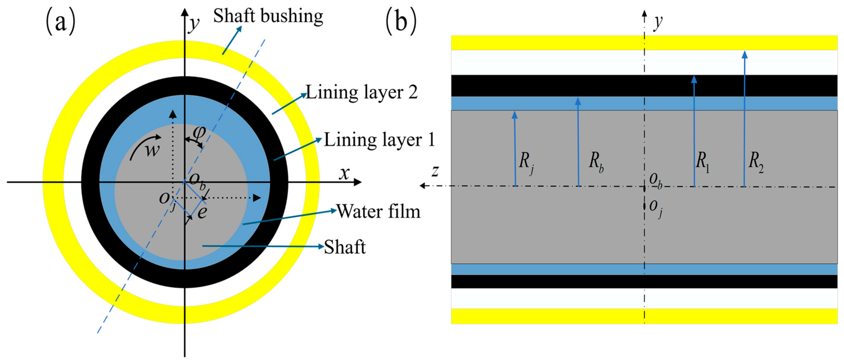
Figure 1. Schematic diagram of the water-lubricated bearing model with a laminated structure: (a) Solid domain; (b) Fluid domain.
Lubricants 13 00445 g001
Figure 4. Flowchart of system calculation and solution process.
Lubricants 13 00445 g004
Figure 5. Pressure distribution contours under varying rotational speeds at a fixed eccentricity of 0.5: (a) 200 r/min; (b) 400 r/min; (c) 600 r/min; (d) 800 r/min; (e) 1000 r/min; (f) 1200 r/min.
Lubricants 13 00445 g005
Figure 6. The influence of eccentricity on various parameters: (a) Maximum water film pressure; (b) Bearing capacity; (c) Friction force; (d) Friction power loss.
Lubricants 13 00445 g006
Figure 7. Deformation cloud diagrams: (a) Deformation cloud diagram of layer 1; (b) Deformation cloud diagram of layer 2.
Lubricants 13 00445 g007
Figure 8. The effect of eccentricity on maximum deformation: (a) Lining 1; (b) Lining 2.
Lubricants 13 00445 g008
Figure 9. Stress cloud diagrams: (a) Stress cloud diagram of liner 1; (b) Stress cloud diagram of liner 2.
Lubricants 13 00445 g009
Figure 10. Influence of eccentricity on maximum stress: (a) Lining 1; (b) Lining 2.
Lubricants 13 00445 g010
Figure 11. Strain cloud diagrams: (a) Strain cloud diagram of liner 1; (b) Strain cloud diagram of liner 2.
Lubricants 13 00445 g011
Figure 12. The influence of eccentricity on the maximum strain: (a) Lining 1; (b) Lining 2.
Lubricants 13 00445 g012
Figure 13. The influence of rotational speed on various parameters: (a) Maximum water film pressure; (b) Load-carrying capacity; (c) Friction force; (d) Friction power loss.
Lubricants 13 00445 g013
Figure 14. Influence of rotational speed on maximum deformation: (a) Lining 1; (b) Lining 2.
Lubricants 13 00445 g014
Figure 15. Influence of rotational speed on maximum stress: (a) Lining 1; (b) Lining 2.
Lubricants 13 00445 g015
Figure 16. The influence of rotational speed on maximum strain: (a) Lining 1; (b) Lining 2.
Lubricants 13 00445 g016
Figure 17. Influence of the thickness of the lining 1 on various parameters: (a) Maximum water film pressure; (b) Bearing capacity; (c) Friction force; (d) Friction power loss.
Lubricants 13 00445 g017
Figure 18. The effect of Layer 1 thickness on maximum deformation: (a) Lining 1; (b) Lining 2.
Lubricants 13 00445 g018
Figure 19. The influence of the thickness of layer 1 on the maximum stress: (a) Lining 1; (b) Lining 2.
Lubricants 13 00445 g019
Figure 20. The effect of Layer 1 thickness on maximum strain: (a) Lining 1; (b) Lining 2.
Lubricants 13 00445 g020
Figure 21. The influence of the thickness of the lining 2 on various parameters: (a) The maximum water film pressure; (b)The bearing capacity; (c) The friction force; (d) The friction power loss.
Lubricants 13 00445 g021
Figure 22. The effect of Layer 2 thickness on maximum deformation: (a) Lining 1; (b) Lining 2.
Lubricants 13 00445 g022
Figure 23. The influence of the thickness of the liner 2 on the maximum stress: (a) Lining 1; (b) Lining 2.
Lubricants 13 00445 g023
Figure 24. The influence of the thickness of the liner 2 on the maximum strain: (a) Lining 1; (b) Lining 2.
Lubricants 13 00445 g024
Figure 25. Schematic diagram of the structure of the test block of the water-lubricated bearing material with a laminated structure: (a) Structural schematic diagram; (b) Photograph of the specimen structure.
Lubricants 13 00445 g025
Figure 27. Changes in the friction coefficient of laminated structures under various loading ratios: (a) 0.15 Mpa; (b) 0.38 Mpa; (c) 0.61 Mpa; (d) 0.84 Mpa.
Lubricants 13 00445 g027
Figure 28. Schematic diagram of the energy dissipation path of the bearing.
Lubricants 13 00445 g028
Table 3. Parameters of liner grid and water film.
ParameterLining 1Lining 2Water Film
Number of nodes3,704,1863,959,326472,416
Number of units806,673862,848235,616
Unit mass0.98130.981350.71451
Aspect ratio1.08821.09042.3224
Skewness9.2024 × 10−28.9033 × 10−23.3784 × 10−3
Jacobi ratio (MAPDL)1.07321.07491.0053
Jacobi ratio (angular node)0.947040.946830.99474
Jacobi ratio (Gauss point)0.958620.95840.99696
Orthogonal quality0.980970.981710.93264
Disclaimer/Publisher’s Note: The statements, opinions and data contained in all publications are solely those of the individual author(s) and contributor(s) and not of MDPI and/or the editor(s). MDPI and/or the editor(s) disclaim responsibility for any injury to people or property resulting from any ideas, methods, instructions or products referred to in the content.