Article

An Analysis on Negative Effects of Shaft Deflection on Angular Misalignment of Rollers Inside Tapered Roller Bearing

School of Mechatronical Engineering, Henan University of Science and Technology, Luoyang 471023, China
*
Author to whom correspondence should be addressed.
Lubricants 2025, 13(10), 438; https://doi.org/10.3390/lubricants13100438
Submission received: 27 August 2025 / Revised: 25 September 2025 / Accepted: 30 September 2025 / Published: 2 October 2025
(This article belongs to the Special Issue Nonlinear Dynamics of Frictional Systems)

Abstract

Shaft deflection degrades roller alignment and intensifies stress concentration/edge effects at roller-ends and raceway edges, ultimately compromising service performance of tapered roller bearings (TRBs). Therefore, a dynamic model was developed for a TRB subjected to a deflected shaft in which Johnson’s load–deformation relationship was applied to reflect non-uniform cross-sectional structures of the tapered rollers and raceways, viscous damping was integrated into the roller/cage interaction, and friction actions at the raceways and flange areas were treated separately. Then, moment load and angular misalignment of the tapered roller were analyzed under various shaft deflection and operating conditions. Results indicate that tilt angle remains orders of magnitude smaller than skew angle. Shaft deflection amplifies both skew and tilt, and the influence level is proportional to the bearing size. Centrifugal effect primarily affects skew motion, whereas gyroscopic effect mainly influences tilt motion. Axial forces exert greater influence on roller skew than tilt. The flange typically constrains roller skew, whereas both raceways may induce bidirectional tilt/skew motion.

1. Introduction

In some machines, such as high-speed trains, automobiles, and rolling mills, the tapered roller bearing is widely used as a swivel and support component, as it can withstand combined radial and axial forces. However, due to installation error, mass mounted on the shaft, and load from gear systems, etc., the bearing shaft would be more or less deflected [1,2]. For certain slender shaft and bearing systems, the shaft may also experience deflection during rotation due to its inherent elastic modal behavior [3,4,5]. The deflected shaft, in turn, occasions the TRB, both rollers and rings, in a misaligned state. In addition, even for aligned TRB, the roller is always in a misaligned state due to normal and tangential interactions with the cage and rings [6,7,8,9]. Here, it refers to the angular misalignment caused by the roller tilt and skew [6]. Eventually, the misaligned state will aggravate the stress edge/concentration effect at the roller/raceway pair, and weaken load-carrying capacity and service life of the TRB [9,10]. Given this situation, the angular misalignment of rolling elements inside the TRB subjected to the aligned or deflected shaft needs to be addressed, as it will lay the foundation for the roller profile design and the bearing service life analysis [9,11].
For prediction of the roller’s motions, the dynamic approach is one of the effective theoretical solutions. Gupta [6] established a basic framework for modeling TRB dynamics. The analysis in this paper mainly refers to Gupta’s work. Deng et al. [8] evaluated effects of operating conditions, cage pocket clearance, and flange frictional behavior on the roller’s tilt and skew. In this work, lubrication states at the bearing contacts were involved. Sakaguchi et al. [12] simulated the skew motion with commercially available software, and friction forces at the TRB contacts were determined by considering both the oil film and asperity contact factors. Wang et al. [13] established a dynamic model of cylindrical roller bearings assessing load distribution and roller misalignment under combined loads.
The static, quasi-static, and quasi-dynamic approaches are also employed for analyzing the roller’s behavior. With consideration of bearing structure and kinematics, Creju et al. [7] developed a quasi-dynamic model for the TRB operating under combined loads and flooded lubrication conditions. Assuming that the TRB is oil-rich lubricated, Nelias et al. [14] developed a quasi-static model to determine the roller’s skew angle, but the roller/cage interplay was not considered. John et al. [15] employed static analysis to the tilt and contact of the cylindrical roller under shaft deflection caused by applied force. In addition, Li et al. [16] developed a 5-DOF static model of single-row TRBs for doubly supporting the wind turbine, which considered the axial preload, cone defection, and roller crown. In John et al.’s [15] and Li et al.’s [16] works, the roller skew was not included. Similarly, other studies on stiffness and fatigue of TRBs also ignored the roller skew issue [17,18,19].
Some roller analyses are performed on commercial software [20,21,22]. Based on ANSYS/LS-DYNA, Xia et al. [20] analyzed dynamic vibration characteristics of the TRB, and the friction coefficient was fixed at 0.1 (static) and 0.05 (dynamic) for the bearing contacts. With the assumptions that all frictions are ignored and pure rolling without slipping of the TRB, Yang et al. [21] studied the mechanical behavior of double-row TRB under moment loads with static method. With the similar assumptions in [21], Razpotnik et al. [22] presented a bottom-up approach to characterizing the dynamics of the TRB.
Zhou et al. [23] developed a fluid–solid coupling lubrication model using the full-system finite element method for an aero-–engine main bearing, and the effects of the roller tilt and skew were investigated. Similarly, Liu et al. [24] analyzed this problem using a fully numerical method, and all indicate that the roller’s angular misalignment significantly affects lubrication.
Some studies experimentally investigated roller misalignment [25,26,27,28,29,30]. Yang et al. [25,26] and Falodi et al. [27] used the same test method and different sensors to measure the roller’s skew angle in single-row and double-row TRBs, respectively. This provides a reference for the theoretical analysis in this paper. To validate the defined friction model at the flange/roller-end contact, Majdoub et al. [28,29] experimentally evaluated roller skew and compared the results with those from the kinematic equilibrium model. The defined friction model is based on the film thickness ratio, and does not explicitly include the sliding–rolling characteristic at the flange. Shafiee et al. [30] designed a novel test rig employing high-speed camera technology to observe roller slide, tilt, and skew behaviors in real-time for double-row spherical roller bearings.
This paper aims to clarify the tapered roller’s alignment state inside the oil-lubricated TRB when the shaft is deflected. So, differential equations of the TRB dynamics, which contain actual structures of the bearing parts, as well as fluid actions at the bearing contacts, were presented to describe angular vibration of the tapered roller. Then, by equating the shaft deflection as a constant angular constraint of the TRB, effects of the deflected shaft on the roller tilt and skew were numerically analyzed. Meanwhile, the roller’s angular misalignment under different operating conditions was studied.

2. Theoretical Formulation

The TRB is a type of roller bearing with strong structural nonlinearity. As depicted in Figure 1a,b, the inertial frame oi-xiyizi is arranged at the cone’s mass center, and the cone body-fixed frame ob-xbybzb coincides with the oi-xiyizi frame in the original state. The cone is shaft-mounted with a tight fit, so shaft deflection can be regarded as the cone’s axis ob-xb unparalleled to the inertial axis oi-xi. Body-fixed frames or-xryrzr (roller) and op-xpypzp (cage) are similarly fixed at their respective mass centers. Thus, translations and rotations of the TRB parts are described in the inertial frame and body-fixed frames, respectively. Bearing internal interactions are solved with reference to Gupta’s method [6]. Assuming the cup is macroscopically stationary, the cone rotates about the ob-xb axis at a constant speed ωi. The roller’s angular misalignment refers to the tilt and skew motions [6].

2.1. Roller/Raceway Interaction

As illustrated in Figure 1c, the roller/raceway interaction is dealt through the slicing method [6,10], wherein the roller is discretized into *s* slices. Unlike cylindrical roller bearings, TRB rollers and raceways exhibit non-uniform cross-sections. To characterize this geometry, Johnson’s load–deformation relationship [31] is applied. Accordingly, the normal force of the *k*-th slice with the cone and cup is
q i , o = ± π l e δ i , o E ¯ rb s 2 ln 4 R ¯ i , o 2 R ¯ i , o δ i , o 1 1
1 E ¯ rb = 1 2 1 υ r 2 E r + 1 υ b 2 E b
R ¯ i , o = k e R r R i , o R r ± R i , o
k e = 1 + 2 sin 2 α h + 4 sin 4 α h sec 2 α h cos α h + sin α h tan 2 α h
where δi,o represent contact deformations; Rr,i,o are radii of the roller and raceways at the *k*-th slice; and ke is projection coefficient of Rr,i,o in the oci-ycizci/oco-ycozco plane.
Deformations δi,o are derived from roller/ring positions [6]. For the inner raceway, the contact point e in the ob-xbybzb frame is
r i = T i ib v + T i ir x r , R r sin ϑ , R r cos ϑ u
where T i ib 0 , ξ , ζ denotes the conversion matrix from the oi-xiyizi frame to the ob-xbybzb frame, ξ and ζ are shaft/cone deflection angles; T i ir β , θ , ϕ is conversion from the oi-xiyizi frame to the or-xryrzr frame, β, θ and ϕ denote rotation, tilt, and skew angles of the *j*-th roller, respectively; and ϑ is computed under the constraint that ri3 is maximized [6]. For calculations δi and δo, u denotes the displacement of the cone and cup in the oi-xiyizi frame, respectively.
Then, the deformation δi at the *k*-th slice in the contact frame oci-xciycizci is
δ i = R i r i 1 r i 2 2 + r i 3 2 cos α h
If the interference δi > 0, it means that the contact takes place. The derivation of δo is similar to that of δi. Then, the friction force at the *k*-th slice is
f i , o = μ bi , bo q i , o
The friction coefficient μb is governed by the lubrication state at the slice/raceway pair. Three states may occur: boundary (BL), mixed (ML), and full-film lubrication (FL). Under the BL state, μb is adapted from Kragelskii’s model [32]. For the FL state, μb is calculated with the experimental regression formula in Wang’s study [33]. Consequently, μb is defined as follows [12,32,33]:
μ b = 0.1 + 22.28 s r exp 181.46 s r + 0.1               if       λ < λ bd μ bd μ hd λ bd λ hd 6 λ λ hd 6 + μ hd                                                   if       λ bd λ < λ hd A + B s r exp C s r + D                                                         if       λ hd λ
where sr is the slide-to-roll ratio at the *k*-th slice; A, B, C, and D are functions of oil parameters, normal load, and velocity of the two contact bodies [33]; λ is film thickness ratio, λ = hm/σ, with λbd = 0.01 and λhd = 1.50.
The central film thickness hm at the *k*-th slice is [34]
h mi , mo = 2.922 l e 0.166 α 1.162 R ¯ i , o 1.474 q i , o 0.166 u ei , eo 0.692 E ¯ rb 0.056 s 0.166
where uei,eo are oil entrainment speeds at the inner/outer contacts.
Then, in the contact frame oc-xcyczc, the interaction force at the *k*-th slice is
Q i , o j k = 0 , f i , o j k , q i , o j k T
where the directions of f i , o jk depend on the relative speed between the roller surface and the raceway surface.

2.2. Flange/Roller-End Interaction

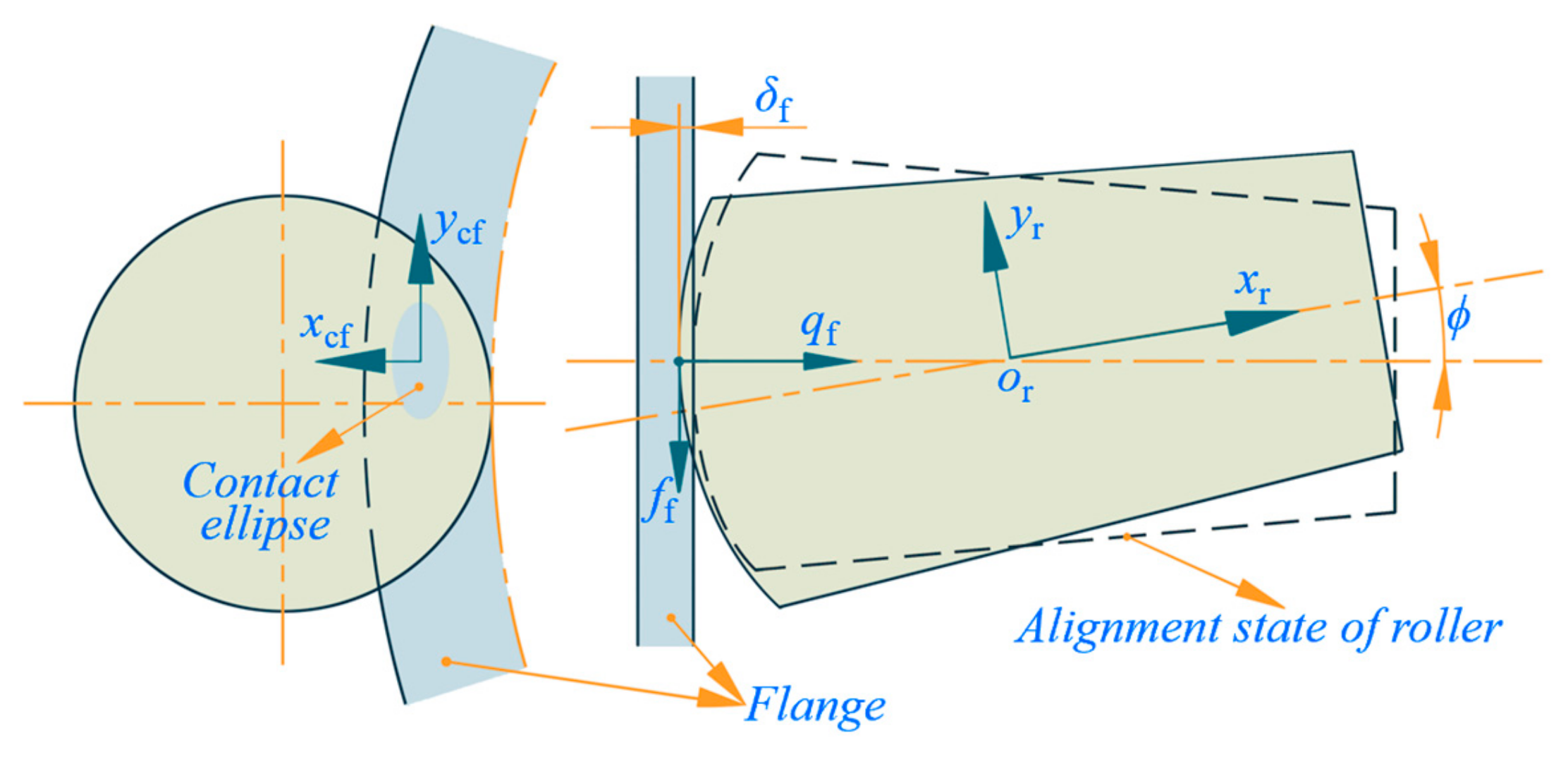
As shown in Figure 2, the conical flange and spherical roller-end forms a typical elliptical contact, so the normal force at this contact is [31]
q f = c v E ¯ rb 3 2 δ f δ 0 c v 3 / 2
where δf is contact deformation [6]; cv is the sum of principal curvatures; and δ0 is a geometry-dependent constant.
For the derivation of δf, the spherical center of the roller-end in the ob-xbybzb frame is
r sb = T i ib v + T ir x rs , 0 , 0 T u
where x rs j locates the spherical center on the or-xr axis.
Then, the flange frame of-xfyfzf is arranged at the point of (see Figure 1c), and its axes are parallel to the ocf-xcfycfzcf frame. The spherical center in the of-xfyfzf frame is
r sf = T f af T f ba r sb r fa
where T f ba ψ , 0 , 0 is a conversion from the cone frame to the azimuth frame, with ψ = tan−1 (rsb2/rsb3); rfa stands for position of of in the azimuth frame; and T f af 0 , α f , 0 is a conversion between the azimuth and flange frames.
Then, the deformation δf of the *j*-th roller with respect to the flange is
δ f = R s r fs 1
Tangential friction at the flange also depends on the lubrication state, and the friction coefficient μf under ML and BL states is the same as that at the roller/raceway pair. Since the slide-to-roll ratio in Wang’s experiments reached only 0.20 [33], to address flange/roller-end traction at a higher ratio (sr is about 0.25~0.50), the viscous shear force is addressed, as it significantly exceeds the rolling resistance force [12]. The traction force ff is
f f = a + a b + b τ x , y d x d y
τ x , y = η x , y u flange u end h c
η x , y = η 0 exp ln η 0 + 9.67 1 + 1 + 5.1 × 10 9 p f x , y z 0
where uflange and uend are surface velocities of two contact bodies; pf is film pressure, pf = ph(1 − x2/a2y2/b2)1/2; z0 is pressure–viscosity index, typically 0 ≤ z0 ≤ 0.8 [35], in this paper z0 = 0.4.
The central film thickness hc at the flange/roller-end contact is [36]
h c = 4.310 α 1.170 R ¯ f 0.466 u ef 0.680 E ¯ rb 0.117 q f 0.073 1 e 1.280 χ j
where uef and R ¯ f are oil entrainment speed and effective radius in the ocf-ycf direction.
Accordingly, in the contact frame ocf-xcfycfzcf, the interaction force at the flange/roller-end contact is
Q f j = f fx j , f fy j , q f j T
where the directions of ffx and ffy are determined by the relative surface speeds between the roller-end and the flange in the ocf-xcf and ocf-ycf directions.

2.3. Roller/Cage Interaction

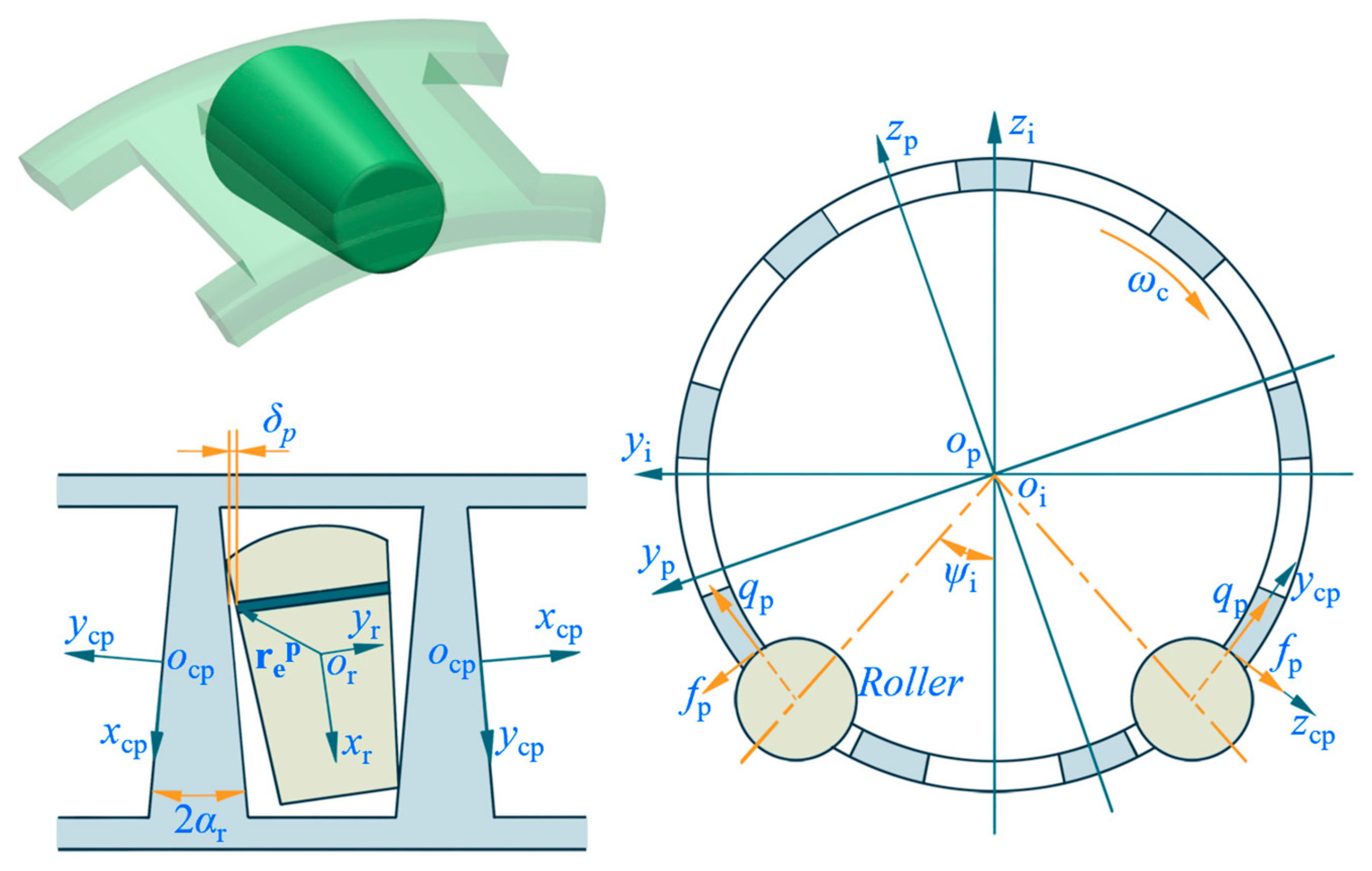
Due to differences in displacement and velocity, the master–slave relationship of the cage and roller evolves dynamically. In Figure 3, the contact frame ocp-xcpycpzcp is located at the pocket wall that is in contact with the roller. Define Δp as the critical film thickness for contact state transition, and Δp is the composite roughness of contact surfaces. When pocket clearance δp at the *k*-th roller slice is greater than Δp, i.e., δp ≥ Δp, the slice/pocket is deemed in the hydrodynamic contact. The normal force qp generated by the film pressure and the traction force fp produced by the film shearing are [37]
q p = q pe = 2.44 l e η 0 u r + u p R r δ p s
f p = 4.58 l e η 0 u r + u p R r 1 / 2 δ p s
where ur and up are surface speeds of the pocket and roller in the ocp-xcpycpzcp frame, respectively.
When δp < Δp, the *k*-th roller slice and the cage pocket are in Hertzian contact. The interaction forces are
q p = q pe + δ p Δ p k ph + δ ˙ p c ph
f p = μ p q p
where kph is Hertzian linearized contact stiffness [38]; cph is viscous damping from Herbert’s model [39]; and μp is the boundary friction coefficient [32]. The kph and cph are as follows:
k ph = π l e 2 s 1 υ r 2 E r + 1 υ p 2 E p 1
c ph = 2 m k ph ln κ 2 ln κ 2 + π ,   m = 1 m r + 1 m p 1 , κ = 1 0.026 δ ˙ p 1 / 3
Then, in the contact frame ocp-xcpycpzcp, the interaction force of the *k*-th roller slice with the pocket is
Q p j k = 0 , f p j k , q p j k T

2.4. Cage/Guiding-Ring Interaction

The cage/guiding-ring interaction (centering and guiding surfaces) follows the same treatment as the roller/cage assembly. When clearance δg < Δg, Hertzian contact dominates and can be modeled using Equations (22) and (23). For the case of δg ≥ Δg, hydrodynamic action can be approximated as a short journal bearing. The resulting hydrodynamic force qg and traction force fg are [37]
q g = η 0 u eg b c 3 ε c 2 1 ε 2 16 ε 2 + π 2 1 ε 2 16 1 ε 2 2
f g = 2 π η 0 u eg R c b c c 1 1 ε 2 1 / 2
Then, the interaction force at the cage/ring interface is
Q g = 0 , f g , q g T

2.5. Differential Equations of TRB Dynamics

The motion of the tapered roller contains six degrees of freedom, and its translational motion is described in the cylindrical frame oi-xiriθi. Considering centrifugal and gyroscopic effects, the differential equations for the *j*-th roller are
m r x ¨ r j , m r r r j θ ¨ r j + 2 m r r r j θ ˙ r j , m r r ¨ r j m r θ ˙ r j 2 T = k = 1 s T i ci Q i j k + k = 1 s T o ci Q o j k + k = 1 s T p ci Q p j k + T f ci Q f j k
d H r j d t + ω ˙ r j × H r j = k = 1 s r i j k × T i cr Q i j k + k = 1 s r o j k × T o cr Q o j k + k = 1 s r p j k × T p cr Q p j k + r f j × T f cr Q f j + 0 , M gr j , 0 T
where [xr, rr, θr]T is roller displacement; Hr is roller angular momentum; ωr is roller angular velocity; T i , o , p , f ci are conversion matrices from contact frames oc-xcyczc at the rings, cup, and flange to the oi-xiriθi frame; T i , o , p , f cr are conversions from the frames oc-xcyczc to the roller frame or-xryrzr; and r i , o , p , f are locations of contact points e in or-xryrzr.
Neglecting overturning in the radial plane oi-yizi, the cage consists of four degrees of freedom. The differential equations for the cage are
m p x ¨ p , m p y ¨ p , m p z ¨ p T = j = 1 n k = 1 s T p ci Q p j k + T g ci Q g
d H p d t + ω ˙ p × H p = j = 1 n k = 1 s r ep j k × T p cp Q p j k + r eg × T g cp Q g
where [xp, yp, zp]T is the cage displacement; Hp is cage angular momentum; ωp is angular velocity; T p , g ci are conversion matrices from contact frames oc-xcyczc at the cage pocket and the guiding ring to oi-xiyizi; T p , g cp are conversion matrices from the frames oc-xcyczc to the cage frame op-xpypzp; and rep,eg denote locations of contact points e in op-xpypzp.
The cone’s differential equations are similar to those of the cage, and it consists of three translational freedoms in the oi-xiyizi frame. Additionally, the shaft deflection is equivalent to a constant angular displacement constraint to the cone.

3. Numerical Method

The parameters of the tapered roller bearing and oil lubricant used for the present study are detailed in Table 1. The bearing operates at an ambient temperature of 25 °C. Differential equations (30~33) of the TRB dynamics were numerically solved with the Gill equation and the Miline–Hamming predictor–corrector method. For the TRB initial state, supposing tapered rollers are evenly distributed and symmetrically distributed about the oi-zi axis, the cage is also in alignment state.

4. Results and Discussions

The behavior of the tapered roller can be regarded as a function of factors such as the structure, load-carrying, and lubrication of the TRB. Tilt and skew phenomena of the roller in the case of aligned shaft or cone have been emphasized in quantities of literatures, and effects of operating conditions and structural parameters on it have been revealed [6,7,8,10,11,12,13,14,25,26,27,28,29,30]. Nevertheless, when the TRB is subjected to deflected shaft or cone, the roller’s behavior would be more complicated, as well as effects of operating conditions.

4.1. Effects of Shaft Deflection on Roller Behavior

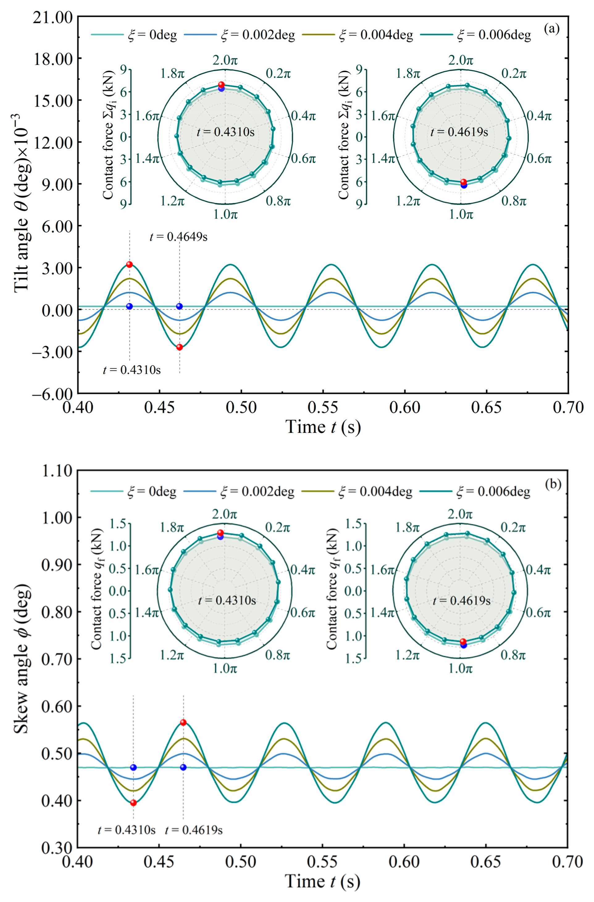
Generally, shaft deflection is undesirable for the bearings that do not have a spherical capacity, but the problem may be unavoidable for certain machines. Therefore, it is necessary to clarify negative effects of the deflected shaft on the roller’s behavior, which is conducive to improve service reliability and safety of the TRB. Figure 4 shows roller angular motions when axial force Fa = 30 kN and bearing speed ωi = 3500 rpm. To avoid the complexity of the issue, the deflection angle is specified directly here. The true deflection angle can be determined by establishing a shaft/bearing elastodynamic model [3].
In Figure 4, if the shaft is in an aligned state (ξ = 0), the roller is already tilted at a negative state (θ < 0) and skewed at a positive state (ϕ > 0). This is associated with the uneven pressure distribution when it is in contact with the raceway and the flange [9]. Moreover, the angular vibrations are consistent with results in [8,14]. Once the shaft is deflected (ξ ≠ 0, deflected direction is based on the right-hand rule), the tapered roller presents a periodic vibration, and the period is about one revolution time of the roller. In addition, tilt and skew vibrations resemble two sine waves with opposite phases. Amplitude of the tilt angle θ is far greater than that when ξ = 0, and it is positively correlated with the deflected angle ξ. Roller skew magnitude is affected in a similar way. No matter how severe the shaft is deflected, the roller is always in a negative skewed state. Polar diagrams in Figure 4 depict distribution of contact forces (Σqi and qf) at the inner raceway and the flange when t = 0.4310 s and t = 0.4619 s. The shaft deflection causes uneven force distribution inside the TRB. The force distribution at the two times is basically similar, revealing that roller misalignment can be approximately predicted by the quasi-dynamic method [6,7].
Figure 5 illustrates contributions of the cup and cone to roller misalignment. When shaft deflection is absent (Figure 5a,b), moments acting on the roller are relatively stable, with tilt moment typically 2~3 orders of magnitude greater than skew moment. It is evident that the sum of moments acting on the roller at any moment does not equal zero, indicating that the forces exerted by the flange and raceways form a triangular set [9]. Based on moment magnitudes, the outer raceway exerts dominant influence on the roller tilt, followed by the inner raceway and flange; meanwhile, the flange has the greatest impact on the roller skew, followed by the outer and inner raceways. If the shaft is deflected (Figure 5c,d), moments exhibit a significant periodic fluctuation with increased amplitudes. The variation of Nft is relatively gentle and always drives the roller toward negative skew. However, the flange’s contribution to the roller tilt is relatively weak compared to both raceways. The directions of Nit and Not are almost opposite (with curve intersection near 0). In Section 2.2, the flange/roller-end is approximated as an elliptical contact. It can be inferred that the shaft deflection may have a different effect on ball bearings than on roller bearings. Regarding skew moment, two raceways induce the roller skewed in both positive and negative directions, but contribute primarily to positive skew most of the time. This is different from the ξ = 0 case. As evident in Figure 5b,d, the flange predominantly hinders the roller skew to some extent.
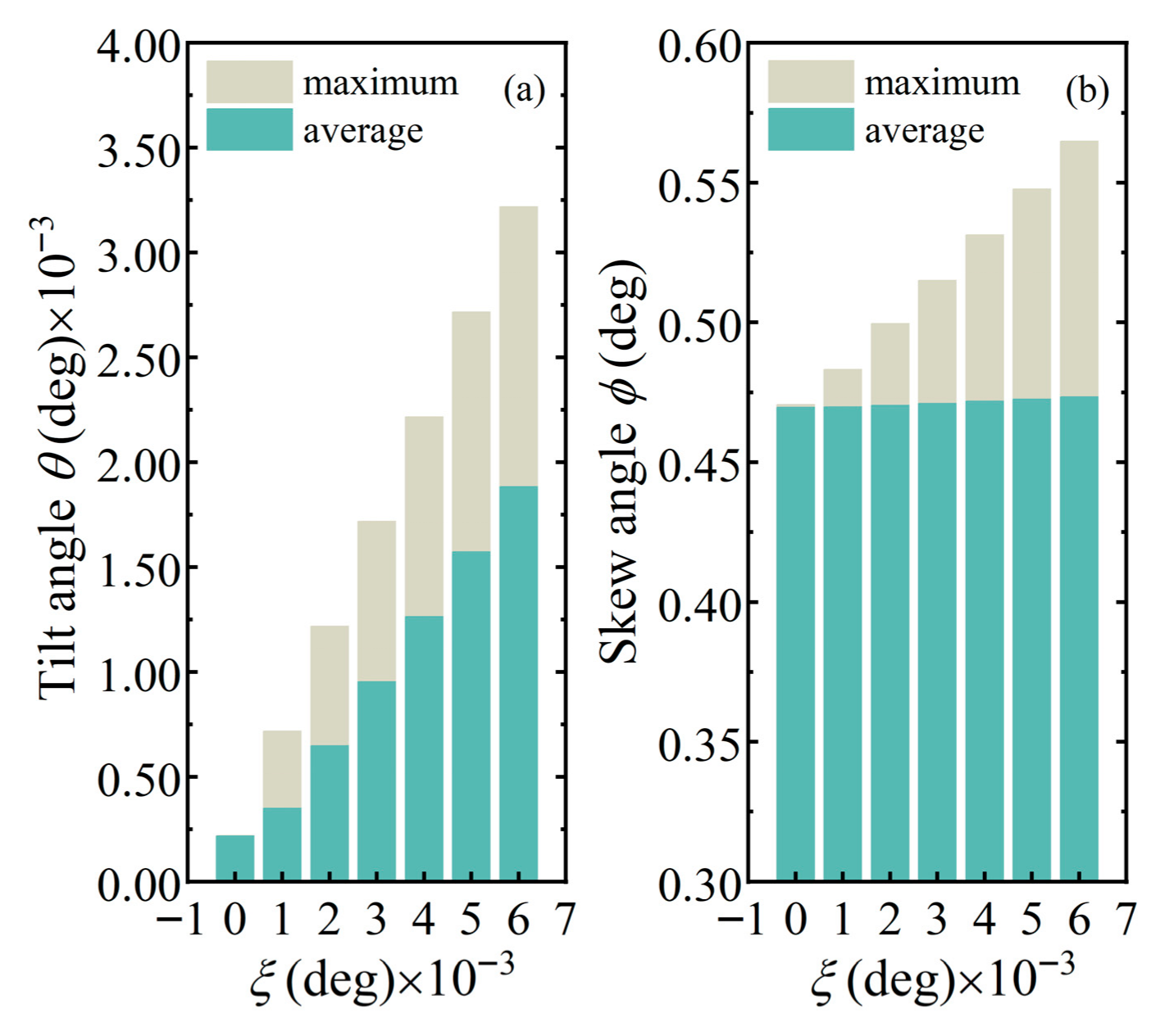
Figure 6 presents statistics of the roller’s angular displacement. As the shaft deflects from 0 deg to 0.006 deg, the average tilt angle θavg is about 2.20 × 10⁻⁴, 3.51 × 10⁻⁴, 6.48 × 10⁻⁴, 9.55 × 10⁻⁴, 1.26 × 10⁻³, 1.57 × 10⁻³, and 1.88 × 10⁻³ deg, and the maximum tilt angle θmax is about 2.21 × 10⁻⁴, 7.17 × 10⁻⁴, 1.22 × 10⁻³, 1.72 × 10⁻³, 2.22 × 10⁻³, 2.72 × 10⁻³, and 3.22 × 10⁻³ deg. It shows that θmax has exceeded the shaft deflection angle ξ. In [40], the TRB’s bore diameter is 30 mm and ξ can reach 5 mrad (about 0.29 deg). In this analysis, they are 130 mm and 0.006 deg. It can be speculated that if the TRB had a large bore diameter, the allowable angle of shaft deflection should be smaller. In the case of ξ = 0, the average ϕavg and maximum ϕmax of the skew angle are about 0.47 deg. Both are comparable to existing works [8,25,26,27], in which the skew angle ϕ is in the ranges of 0.20~0.40 deg [8], 0.15~0.60 deg [25,26], and 0.07~0.42 deg [27]. In addition, the effect of misaligned shaft on ϕavg is mild, while on ϕmax, it is apparent. If angular misalignment of the shaft or cone is relatively large, such as it is in [14], it can reach 0.50 deg, and the skew is also very prominent.
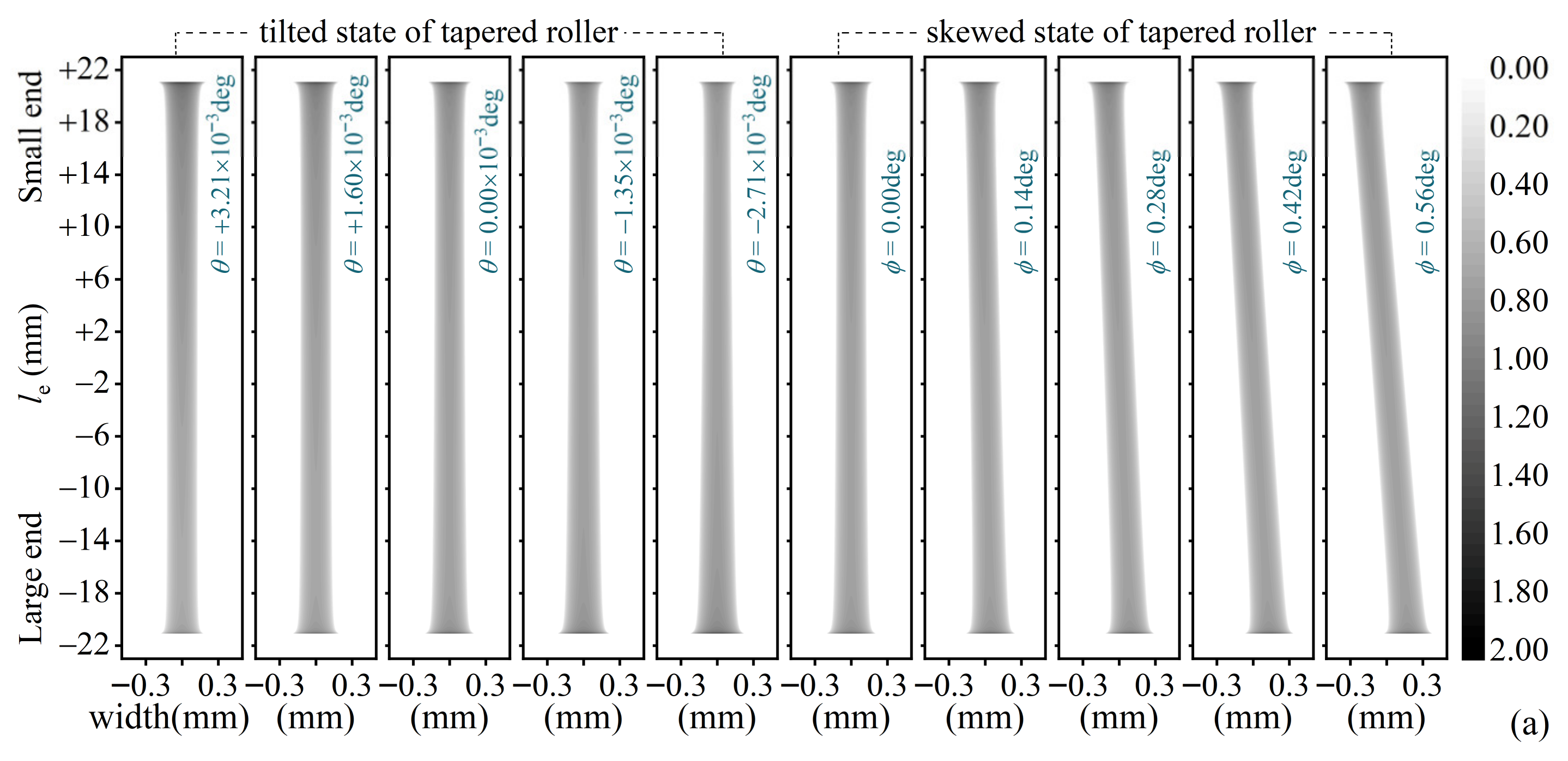
If the tapered roller is in an angular misalignment, the contact with raceways will deviate from expected state. Taking the inner raceway contact as object, referring to maximum load (Σqi)max and angular displacements in Figure 5, the dry contact under tilt and skew states was calculated with the conjugate gradient method (CGM). Among these, the tilt and skew angles serve as displacement constraints for the roller, a treatment analogous to that employed by John et al. [15]. Axis legends in Figure 7 for each cloud plot are the same. In Figure 7a of pressure contours, with the roller tilted from negative to positive, the maximum contact width changes from small end to large end of the roller. The contact area Ωp > 0 skews as the roller skews. In Figure 7b,c, the tilt effect on pressure profile along roller length is remarkable, and it exacerbates the stress edge effect at the roller-end. Because the roller profile crowning is ignored, the edge effect exists in the alignment state (θ = 0). Compared with the tilt, the skew has a slight influence on the pressure profile, which is due to the relatively large radius ratio (it is about 7.37) of the inner raceway to roller. So, although the tilt is slight, its impact on the roller/raceway pair is more profound. Under lubricated conditions, the roller’s angular displacement also induces a change in lubricant entrainment speed, thereby affecting film-forming state inside the bearing [23,24]. Meanwhile, the skew motion is a potential cause of heat generation in roller bearings [27].

4.2. Effects of Operating Parameters on Roller Behavior Under Shaft Deflection

4.2.1. At Different Bearing Speeds

Generally, the TRB is implemented in a certain speed range within the limiting speed. According to the characterization of tangential friction forces, bearing speed ωi is the main factor that induces the roller angular misalignment. The tilt and skew angles can be regarded as roller attitude angles. Figure 8 reveals the attitude angles as a function of operating time at different bearing speeds.
In Figure 8a, as bearing speed ωi rises, the tilt vibration frequency is augmented. This means that in the same time, the number of times the roller is in a severely tilted state is increased. Meanwhile, the accelerated ωi accentuates the roller’s gyroscopic motion, resulting in a decrease in the negative tilt amplitude and an increase in the positive tilt amplitude. In Figure 8b, bearing speed ωi has a significant influence on the roller skew. Similarly, frequency and amplitude of the skew vibration are raised in general.
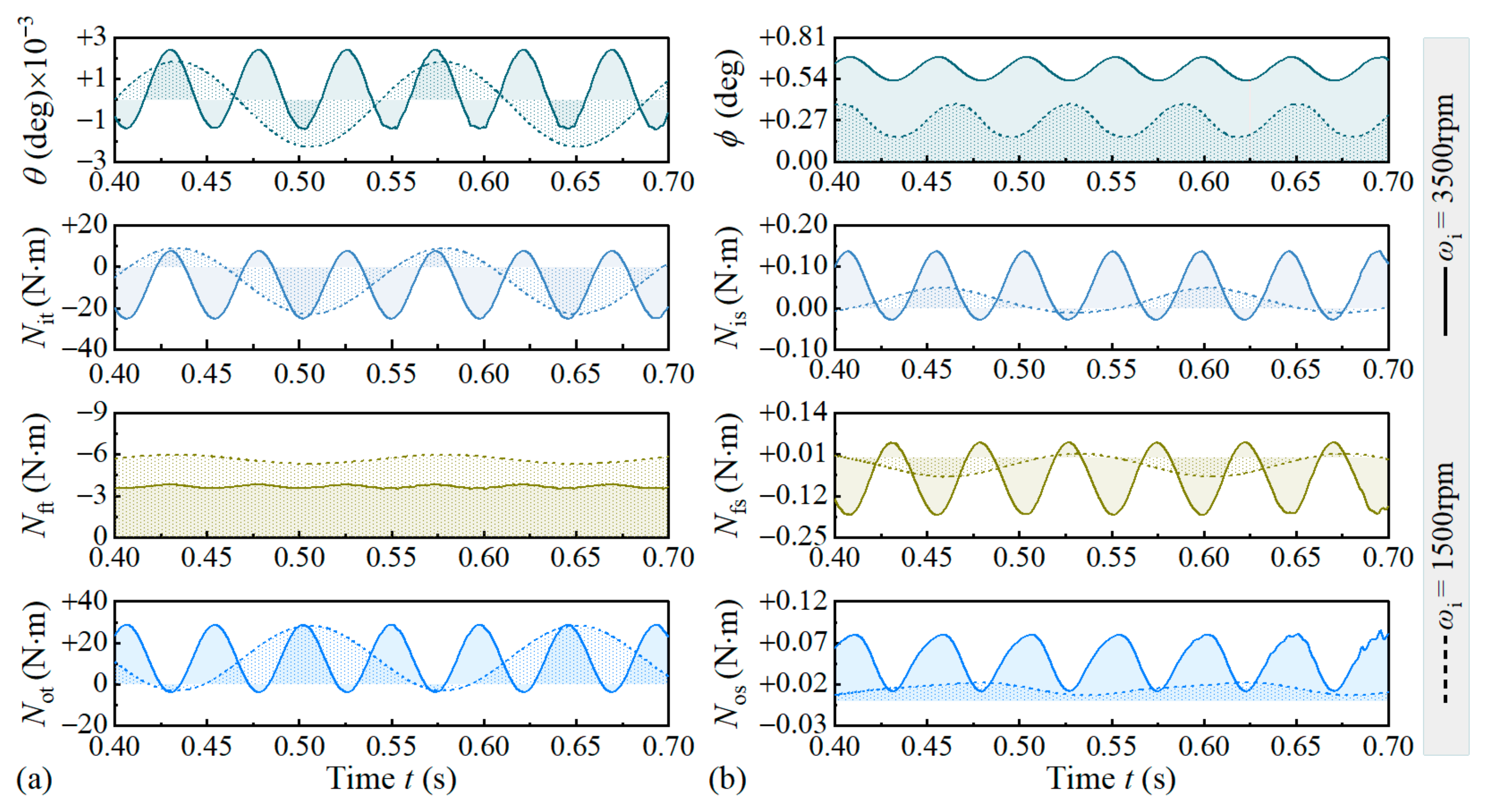
Figure 9 demonstrates that as bearing speed ωi rises, moment fluctuations and angular vibrations always maintain identical cycles. In Figure 9a, the inner raceway keeps the roller tilted in the negative direction, while Not and Nft let the roller tilt in both directions. Furthermore, fluctuation of Nit remains slight across all speeds. It is well known that centrifugal force affects the roller/raceway interaction, but its influence on tilt moment is not significant. In Figure 9b, as bearing speed ωi rises, the skew moment exerted on the roller generally increases. Here, Nis consistently aligns with the skew direction, while the flange moment Nfs prevents the roller from positive skew most of the time. Centrifugal force causes the inner raceway to be ‘relaxed’, resulting in a reduction in contact force. This reduction, however, increases slide-to-roll ratio sr, and ultimately elevates frictional force/moment. In Figure 5 and Figure 9, it can be found that although the flange/roller-end is in sliding–rolling contact, it appears to have a corrective effect on the roller misalignment, and, in particular, on the roller skew.
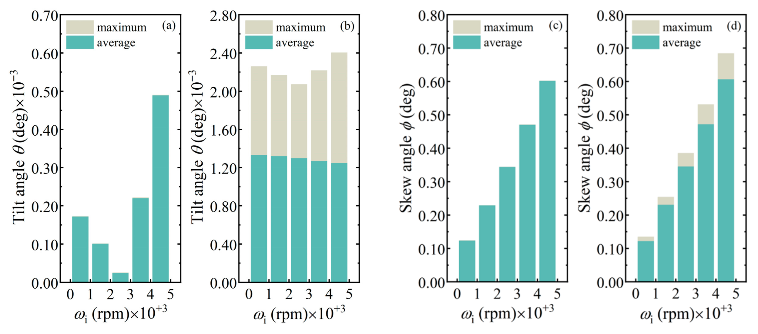
Figure 10a,b displays variations of maximum θmax and average θavg with bearing speed ωi. For ξ = 0, the two are very close, both first decreasing and then increasing as ωi rises. In fact, as a result of the gyroscopic effect, the roller tilt transitions from negative at ωi = 500 rpm to positive at ωi = 4500 rpm. For ξ = 0.004 deg, θmax follows the same variation trend, but θavg shows a decreasing trend. θmax is one order of magnitude higher than when ξ = 0, indicating that the shaft deflection leaves the roller in a serious misalignment state. In Figure 10c,d, increasing trends of the roller skew with bearing speed ωi are basically the same, and skew amplitude is not much different under the ξ = 0 and ξ ≠ 0 cases. As ωi varies from 500 rpm to 4500 rpm, ϕmax is about 0.12, 0.23, 0.34, 0.47, and 0.60 deg subjected to aligned shaft, and it is about 0.13, 0.25, 0.39, 0.53, and 0.68 deg subjected to misaligned shaft.

4.2.2. Under Different Force Loading Conditions

The angular misalignment of tapered roller was analyzed in two loading conditions. Namely, the TRB is loaded by a pure axial force Fa, and is loaded by a radial force Fr (in the oi-zi axis direction) but preloaded by a constant axial displacement δa.
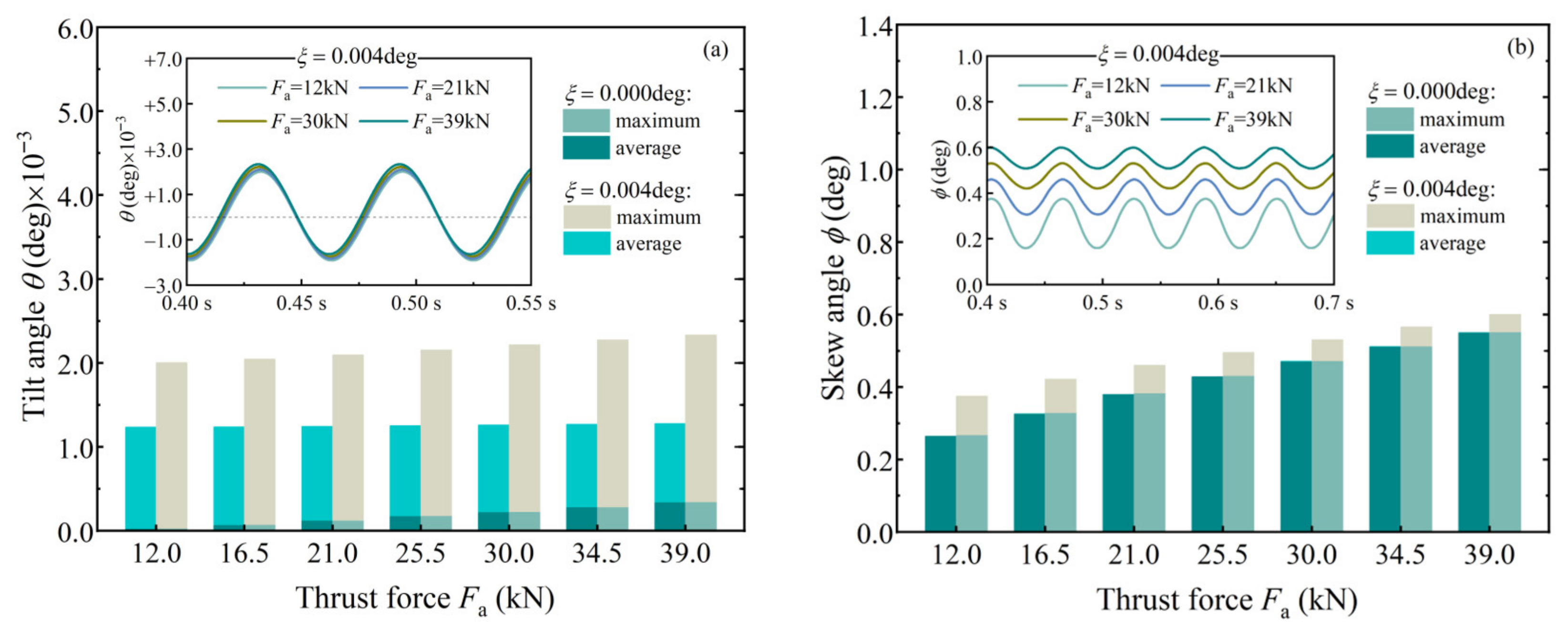
Since axial force Fa will contribute to skew and tilt moments, its increase would inevitably deteriorate the roller’s alignment state. Figure 11 exhibits the deterioration when the TRB carries pure axial force Fa and the shaft is deflected at 0 deg and 0.004 deg. Whether the shaft is deflected or not, tilt fluctuation under different axial forces Fa is consistent. Tilt amplitude increases gradually by a small amount. For the skew motion, the effect of Fa is remarkable, and the amplitude increase is large. For ξ = 0, with Fa varying from 12 kN to 39 kN, θmax is raised from 2.10 × 10⁻⁵ deg to 3.37 × 10⁻⁴ deg and ϕmax is raised from 0.27 deg to 0.55 deg. For ξ = 0.004 deg, θmax and ϕmax are in the ranges of 2.00 × 10⁻³~2.33 × 10⁻³ deg and 0.38~0.60 deg, respectively. The average ϕavg when ξ = 0.004 deg is quite close to ϕavg or ϕmax when ξ = 0. Under the shaft-deflected case, the change of roller skew with axial force Fa is similar to that in [8,14].
Figure 12 displays moments under different axial forces (ξ = 0.004 deg). In Figure 12a, although Fa minimally affects the roller tilt, its perturbation on the tilt moment is pronounced. The moment amplitude increases variably across positions, and Not shifts toward a positive value. Differing sensitivities of the tilt moment and tilt angle to Fa may relate to the structural characteristics of TRBs. In Figure 12b, driven by the axial force Fa, the fluctuation amplitude of the skew moment increases, and Nos similarly shifts toward positive values. Additionally, the disturbance to the flange moment Nfs is relatively obvious.
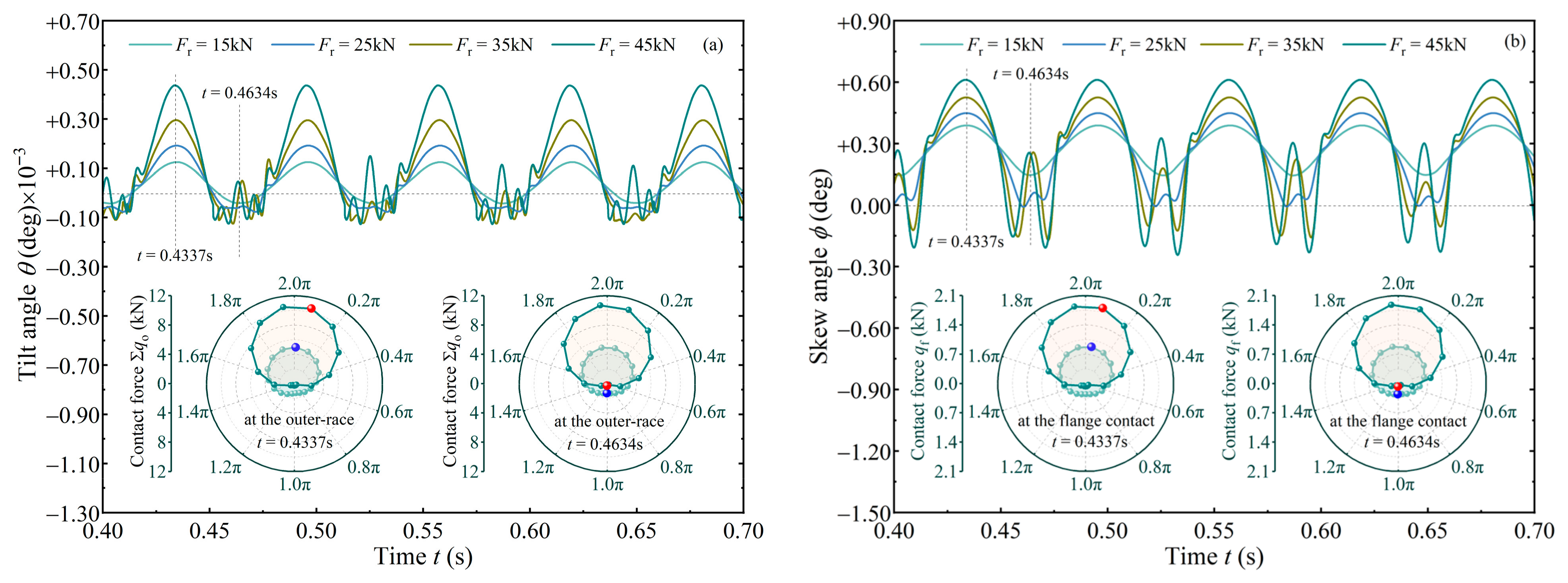
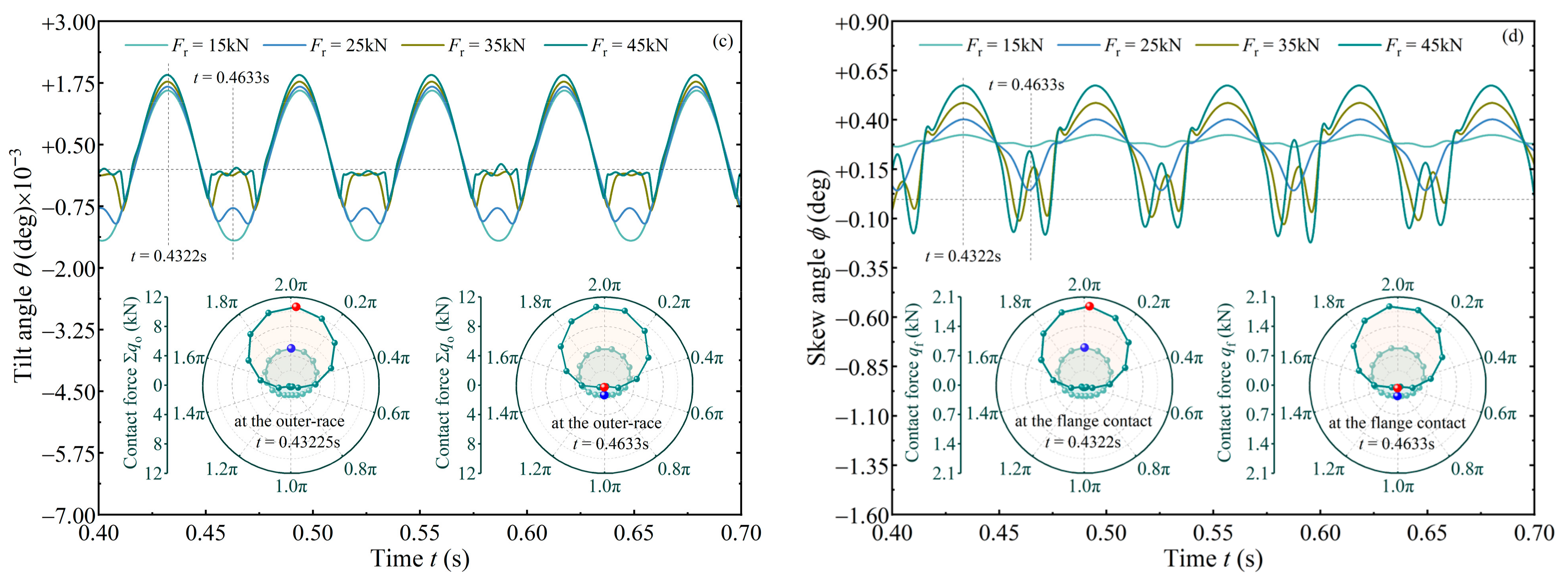
The effects of different radial forces on the roller misalignment were seldom concerned in existing works [12,13,14,25,26,27,28,29,30]. Figure 13 reveals the roller’s angular vibrations under different radial forces and a displacement preload δa. The tilt and skew are quite different from those without radial force Fr (Figure 11). Even if the shaft is aligned (ξ = 0), as exhibited in Figure 13a,b, the roller also shows a periodic angular fluctuation due to Fr. Polar diagrams in Figure 13a,b depict contact forces (Σqo and qf) at the outer raceway and the flange. As Fr increases, the TRB is transformed into a major and a minor load-carrying zone. This means that some rollers bear more load, while others are ‘relaxed’. When Fr = 15 kN, all rollers are in the load-carrying state, and angular fluctuations are relatively gentle. For the heavy loading condition (Fr = 45 kN), the roller fluctuates sharply in the minor or ‘relaxed’ zone. Due to the gyroscopic effect, the roller in the ‘relaxed’ zone tends to be positively tilted. In the major zone, tilt and skew amplitudes increase as radial force Fr increases.
When the shaft is deflected (Figure 13c,d), effects of radial force Fr resemble that when the shaft is aligned. The roller misalignment also amplifies as Fr increases. Additionally, shaft deflection shows no significant impact on force distribution inside the TRB. This situation should be limited to the Fr ≠ 0 and δa ≠ 0 case. Since shaft deflection reduces bearing clearance in the minor zone, the intensity of the roller’s angular motion decreases locally. In the major zone, the disturbance of Fr on tilt amplitude diminishes, though its impact on skew amplitude remains pronounced. The observed skew amplitude remains generally consistent with Nelias’s work [14]. In summary, the roller’s angular misalignment presents a complicated state under varying TRB operating conditions, and shaft deflection unequivocally exacerbates this effect.
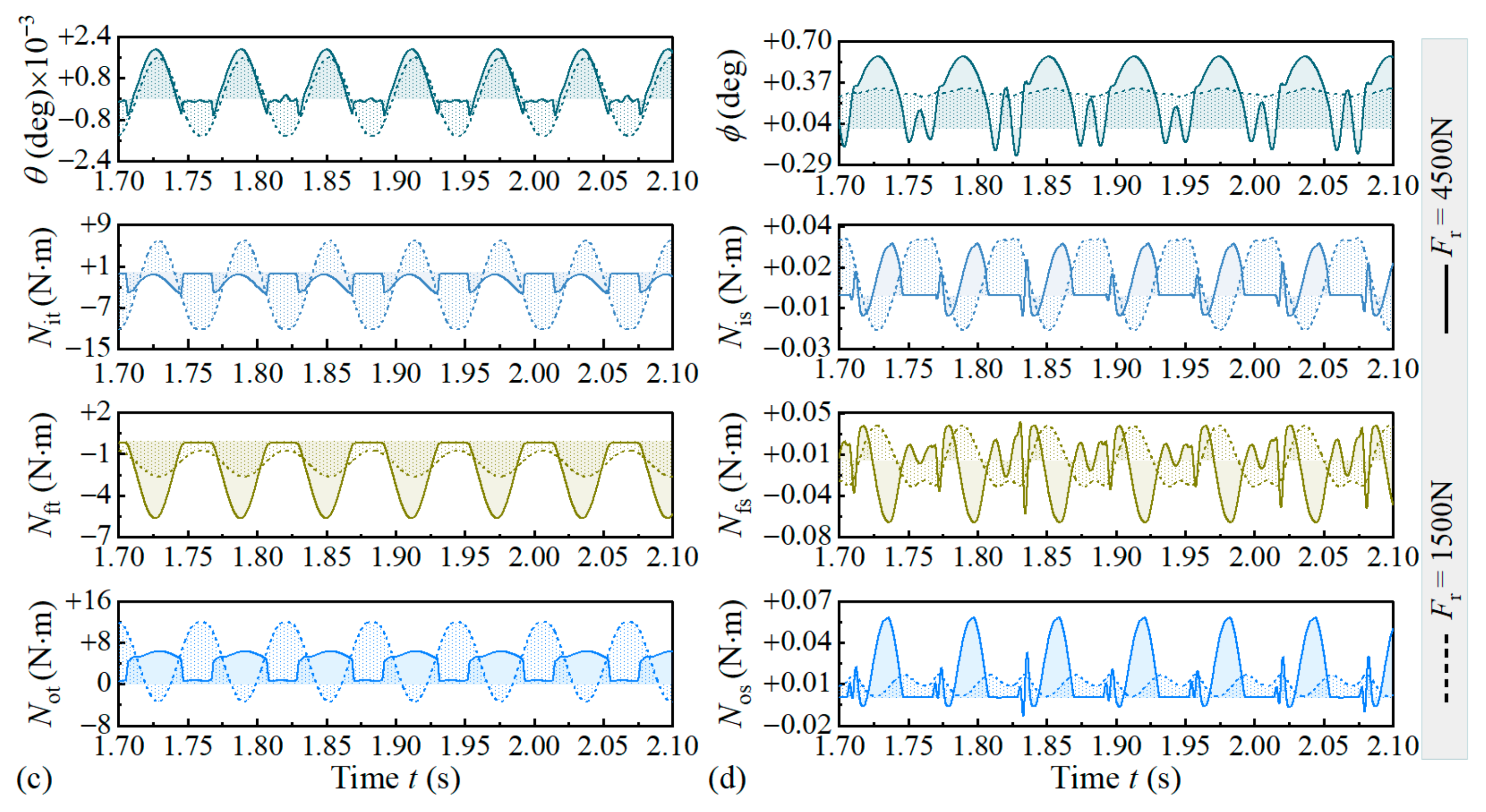
Figure 14a,b illustrates loads exerted on the tapered roller at different radial forces when ξ = 0, and they exhibit the same periodicity as the roller’s angular vibrations. For Fr = 1500 N, rollers are all loaded, so tilt and skew moments fluctuate sinusoidally. For Fr = 4500 N, the minor and major load-carrying zones are evident. In the minor zone, the roller is mainly subjected to centrifugal and gyroscopic effects, yielding a smaller moment load. However, the enlarged bearing clearance induces a significant vibration. In the major zone, variations of tilt and skew moments with time or position match the Fr = 1500 N case, but amplitudes are undoubtedly increased. As the roller just runs into the main zone, a slight instability occurs in the skew moment, causing perturbation to roller skew.
Figure 14c,d illustrates the ξ = 0.003 deg case, and moments acting on the roller are significantly more complex. For Fr = 1500 N, the tilt moment of the rings exerting on the roller is higher than that when ξ = 0. The skew moment loses sinusoidal characteristics, and multiple peaks appear within the minor load-carrying zone. Additionally, skew moment from the outer raceway and flange increases, while little change occurs at the inner raceway. For Fr = 4500 N, the minor and major zones re-emerge with modified boundaries, and tilt and skew moments decrease universally compared to that when ξ = 0. Case comparison shows that at Fr = 1500 N, the deflected shaft reverses overall time trends of Not, Nit, Nos, Nis, and Nfs, and at Fr = 4500 N, it only affects the overall time trend of Nit. This is actually a reflection of structural nonlinearity of TRBs.

5. Conclusions

Differential equations for the TRB dynamics subjected to a deflected shaft were presented, in which the shaft deflection is equivalent to an angular displacement constraint of the TRB. Tilt and skew vibrations of the tapered roller were numerically studied, as well as negative effects of deflected shaft and operating parameters on roller alignment state.
(1)
The amplitude of the tilt moment borne by the roller is 2~3 orders of magnitude higher than the skew moment, but the tilt angle is several orders of magnitude lower than the skew angle. Compared with skew motion, tilt motion is more likely to aggravate the stress edge effect at the roller-end.
(2)
The deflected shaft increases tilt and skew amplitudes of the tapered roller. Tilt amplitude may exceed the deflected angle.
(3)
In aligned and misaligned states of the shaft, both bearing speed and axial force significantly affect roller skew, while slightly affecting tilt motion. These factors similarly influence the moments exerted on the roller by the cone and cup.
(4)
Within the load conditions analyzed, flange drives the roller to tilt toward the negative direction and prevents roller skew most of the time, whereas both raceways may drive the roller to tilt/skew toward either the positive or negative direction.
(5)
When a major and a minor load-carrying zone distinctly exists inside the TRB, the roller will exhibit a pronounced angular vibration when it is in the minor zone or just orbited to the major zone.

Author Contributions

Conceptualization, Z.W. and S.D.; methodology, Z.W.; software, Z.W.; validation, Z.W. and J.K.; formal analysis, J.K.; investigation, Z.W.; resources, S.D.; data curation, Z.W. and J.K.; writing—original draft preparation, Z.W. and J.K.; writing—review and editing, Z.W. and J.K.; visualization, J.K.; supervision, S.D.; project administration, Z.W.; funding acquisition, Z.W. All authors have read and agreed to the published version of the manuscript.

Funding

The paper was founded by the Science and Technology Planning Project of Heilongjiang Province of China (No. 2023ZXJ04A02).

Data Availability Statement

Data are contained within the article.

Conflicts of Interest

The authors declare no conflicts of interest.

Abbreviations

The following abbreviations are used in this manuscript:
TRBTapered roller bearing

Nomenclature

General VariablesδpPocket clearance
aSemi-major axis of contact ellipseεEccentricity of cage, ε = e/c
bSemi-minor axis of contact ellipseη0Oil viscosity at atmospheric pressure
bcWidth of centering surfaceσComprehensive roughness
cRadius gap, c = RcRgτShear stress of oil film
cphViscous dampingυr, υb, υcPoisson’s ratio of roller, ring, and cage, respectively
cvSum of principal curvaturesΔp, ΔgCritical film thickness at the cage pocket and the guiding ring, respectively
eEccentric distance of cageχElliptical ratio
Ec, Eb, ErYoung’s modulus of cage, rings, and roller, respectivelyδi, δo, δfContact deformation at inner raceway, outer raceway, and flange, respectively
hcFilm thickness at the flangeMatrix and Vector
hmFilm thickness at the racewaysHAngular momentum
kphContact stiffnessrPosition vector of contact location
leTotal length of straight generatrix of rollerTTransformation matrix
mrMass of rolleruLinear displacement of cone or cup
mpMass of cagevLinear displacement of roller
nNumber of rollersωAngular velocity
phHertzian contact pressureSuperscript
RcRadius of cage centering surfaceaInertial cylindrical frame
RgRadius of flange guiding surfacecContact frame
RiRadius of inner racewayiInertial frame
RoRadius of outer racewayjThe *j*-th roller
RrRadius of rollerkThe *k*-th roller slice
RsRadius of spherical roller-endpBody-fixed frame of cage
sNumber of slices of rollerrBody-fixed frame of roller
srSlide-to-roll ratioSubscript
ueEntrainment speed of lubricant fFlange
z0Coefficient in Roelands pressure–viscosity modelgGuiding ring
αCoefficient in Barus pressure–viscosity modeliCone or inner raceway
αhHalf-cone angle of rolleroCup or outer raceway
αfFlange contact anglepCage
δgClearance between centering and guiding surfacesrRoller

References

  1. Litwin, W.; Olszewski, A.; Wodtke, M. Influence of shaft misalignment on water lubricated turbine sliding bearings with various bush modules of elasticity. Key Eng. Mater. 2011, 490, 128–134. [Google Scholar] [CrossRef]
  2. Hili, M.A.; Fakhfakh, T.; Hammami, L.; Haddar, M. Shaft misalignment effect on bearings dynamical behavior. Int. J. Adv. Manuf. Technol. 2005, 26, 615–622. [Google Scholar] [CrossRef]
  3. Matsubara, M.; Rahnejat, H.; Gohar, R. Computational modelling of precision spindles supported by ball bearings. Int. J. Mach. Tools Manuf. 1988, 28, 429–442. [Google Scholar] [CrossRef]
  4. Jagadeesha, T.; Salunkhe, V.G.; Desavale, R.G.; Patil, P.B.; Kumbhar, M.B.; Koli, A.R. Investigation of Crack Detection Technique in a Rotating Shaft by Using Vibration Measurement. In Advances in Industrial Automation and Smart Manufacturing. Lecture Notes in Mechanical Engineering; Arockiarajan, A., Duraiselvam, M., Raju, R., Eds.; Springer: Singapore, 2021. [Google Scholar] [CrossRef]
  5. Salunkhe, V.G.; Desavale, R.G. An intelligent prediction for detecting bearing vibration characteristics using machine learning model. J. Nondestruct. Eval. Diagn. Progn. Eng. Syst. 2021, 4, 031004. [Google Scholar] [CrossRef]
  6. Gupta, P.K. Advanced Dynamics of Rolling Elements; Springer Verlag: New York, NY, USA, 1984. [Google Scholar] [CrossRef]
  7. Creju, S.; Bercea, I.; Mitu, N. A dynamic analysis of tapered roller bearing under fully flooded conditions part 1, 2. Wear 1995, 188, 11–18. [Google Scholar] [CrossRef]
  8. Deng, S.; Gu, J.; Cui, Y.; Zhang, W.; Gachot, C. Dynamic analysis of a tapered roller bearing. Ind. Lubr. Tribol. 2017, 70, 191–200. [Google Scholar] [CrossRef]
  9. Rahnejat, H.; Gohar, R. Design of profiled taper roller bearings. Tribol. Int. 1979, 12, 269–275. [Google Scholar] [CrossRef]
  10. Harris, T.A.; Kotzalas, M.N. Advanced Concepts of Bearing Technology: Rolling Bearing Analysis, 5th ed.; CRC Press: Boca Raton, FL, USA, 2006. [Google Scholar] [CrossRef]
  11. Fujiwara, H.; Kawase, T. Logarithmic profile of rollers in roller bearing and optimization of the profile. Trans. Jpn. Soc. Mech. Eng. 2006, 72, 3022–3029. [Google Scholar] [CrossRef]
  12. Sakaguchi, T.; Harada, K. Dynamic analysis of cage behavior in a tapered roller bearing. In Proceedings of the World Tribology Congress III, Washington, DC, USA, 12–16 September 2005. [Google Scholar] [CrossRef]
  13. Wang, Z.; Song, J.; Li, X.; Yu, Q. Modeling and dynamic analysis of cylindrical roller bearings under combined radial and axial loads. J. Tribol. 2022, 144, 121203. [Google Scholar] [CrossRef]
  14. Nelias, D.; Bercea, I.; Paleu, V. Prediction of Roller Skewing in Tapered Roller Bearings. Tribol. Trans. 2008, 51, 128–139. [Google Scholar] [CrossRef]
  15. Johns, P.M.; Gohar, R. Roller bearings under radial and eccentric loads. Tribol. Int. 1981, 14, 131–136. [Google Scholar] [CrossRef]
  16. Li, Y.; Gao, Y. Internal load distribution of single-row tapered roller bearings doubly supporting main shaft of wind turbine. Adv. Mech. Eng. 2022, 14, 105960. [Google Scholar] [CrossRef]
  17. Zhang, K.; Li, Y.; Wang, J.; Xu, L. Fatigue life analysis of double-row tapered roller bearings for heavy trucks. J. Phys. Conf. Ser. 2025, 3043, 012061. [Google Scholar] [CrossRef]
  18. Kim, T.; Suh, J.; Lee, J.; Lee, B.; Yu, Y. Fatigue life prediction of double-row tapered roller bearings considering thermal effect. Adv. Mech. Eng. 2023, 15, 168781322311540. [Google Scholar] [CrossRef]
  19. Zhang, F.; Lv, H.; Han, Q.; Li, M. The effects analysis of contact stiffness of double-row tapered roller bearing under composite loads. Sensors 2023, 23, 4967. [Google Scholar] [CrossRef]
  20. Xia, X.; Li, Y.; Dong, S.; Zhu, W.; Chen, T. Based on ANSYS crown tapered rolling bearings dynamics simulation analysis. J. Intell. Fuzzy Syst. 2018, 34, 1121–1131. [Google Scholar] [CrossRef]
  21. Yang, L.; Xu, T.; Xu, H.; Wu, Y. Mechanical behavior of double-row tapered roller bearing under combined external loads and angular misalignment. Int. J. Mech. Sci. 2018, 142–143, 561–574. [Google Scholar] [CrossRef]
  22. Razpotnik, M.; Bischof, T.; Boltezar, M. The dynamics of tapered-roller bearings—A bottom-up validation study. J. Mech. Eng. 2023, 69, 289–298. [Google Scholar] [CrossRef]
  23. Zhou, L.; Yang, X.; Luo, Z.; Zhang, J.; Li, Z.; Wang, X. Research on the lubrication state of the contact interface under the tilt and skew state of the roller of the aviation bearing. Lubricants 2025, 13, 174. [Google Scholar] [CrossRef]
  24. Liu, X.; Li, S.; Yang, P.; Yang, P. On the lubricating mechanism of roller skew in cylindrical roller bearings. Tribol. Trans. 2013, 56, 929–942. [Google Scholar] [CrossRef]
  25. Yang, Y.; Danyluk, S.; Hoeprich, M. A study on rolling element skew measurement in a tapered roller bearing with a specialized capacitance probe. J. Tribol. 2000, 122, 534–538. [Google Scholar] [CrossRef]
  26. Yang, Y.; Danyluk, S.; Hoeprich, M. Rolling Element Skew in Tapered Roller Bearings. Tribol. Trans. 2000, 43, 564–568. [Google Scholar] [CrossRef]
  27. Falodi, A.; Chen, Y.K.; Caspall, M.; Earthrowl, B.; Dell, D. On the Measurement of Roller Skew of Tapered Roller Bearings. Appl. Mech. Mater. 2012, 217–219, 2328–2331. [Google Scholar] [CrossRef]
  28. Majdoub, F.; Mevel, B. Kinematic Equilibrium of Rollers in Tapered Roller Bearings. Tribol. Trans. 2019, 62, 567–579. [Google Scholar] [CrossRef]
  29. Majdoub, F.; Saunier, L.; Sidoroff-Coicaud, C.; Mevel, B. Experimental and numerical roller skew in tapered roller bearings. Tribol. Int. 2020, 145, 106142. [Google Scholar] [CrossRef]
  30. Shafiee, A.; Russell, T.; Lorenz, S.J.; Sadeghi, F.; Wilmer, M.G. Optical measurement of roller slip, tilt, and skew in a spherical roller bearing. J. Tribol. 2022, 145, 044302. [Google Scholar] [CrossRef]
  31. Johnson, K.L. Contact Mechanics; Cambridge University Press: London, UK, 1985. [Google Scholar] [CrossRef]
  32. Kragelskii, I.V. Friction and Wear; Butterworths: London, UK, 1965; pp. 178–184. [Google Scholar] [CrossRef]
  33. Wang, Y.S.; Yang, B.Y.; Wang, L.Q. Investigation into the traction coefficient in elastohydrodynamic lubrication. Tribotest 2004, 11, 113–124. [Google Scholar] [CrossRef]
  34. Hamrock, B.J.; Schmid, S.R.; Jacobson, B.O. Fundamentals of Fluid Film Lubrication, 2nd ed.; CRC Press: Boca Raton, FL, USA, 2004. [Google Scholar] [CrossRef]
  35. Roelands, C.J.A. Correlational Aspects of the Viscosity-Temperature-Pressure Relationship of Lubricating Oils. Ph.D. Thesis, Technische Hogeschool Delft, Delft, The Netherlands, 1966. Available online: https://resolver.tudelft.nl/uuid:1fb56839-9589-4ffb-98aa-4a20968d1f90 (accessed on 27 August 2025).
  36. Chittenden, R.J.; Dowson, D.; Dunn, J.F.; Taylor, C.M. A theoretical analysis of the isothermal elastohydrodynamic lubrication of concentrated contacts. I. Direction of lubricant entrainment coincident with the major axis of the Hertzian contact ellipse. Proc. R. Soc. Lond. Ser. A Math. Phys. Sci. 1985, 397, 245–269. [Google Scholar] [CrossRef]
  37. Cameron, A. The Principles of Lubrication; Longmans Green and Co., Ltd.: London, UK, 1966; Available online: http://scholar.google.com/scholar_lookup?&title=Principles%20of%20Lubrication&publication_year=1966&author=Cameron%2CA (accessed on 27 August 2025).
  38. Alves, J.; Peixinho, N.; Silva, M.T.; Flores, P.; Lankarani, H. A comparative study on the viscoelastic constitutive laws for frictionless contact interfaces in multibody dynamics. Mech. Mach. Theory 2015, 85, 172–188. [Google Scholar] [CrossRef]
  39. Herbert, R.G.; Mcwhannell, D.C. Shape and frequency composition of pulses from an impact pair. J. Eng. Ind. 1977, 99, 513–518. [Google Scholar] [CrossRef]
  40. Tong, V.C.; Hong, S.W. The effect of angular misalignment on the running torques of tapered roller bearings. Tribol. Int. 2016, 95, 76–85. [Google Scholar] [CrossRef]
Figure 1. Description of shaft deflection, geometric structure, and coordinate frames of the TRB. (a) shaft deflection; (b) inertial and body-fixed frames; (c) contact frames.
Lubricants 13 00438 g001
Figure 2. Interaction between spherical roller-end and conical flange.
Lubricants 13 00438 g002
Figure 3. Interaction between cage and roller.
Lubricants 13 00438 g003
Figure 4. Roller skew and tilt as a function of time subjected to deflected shaft, Fa = 30 kN, Fr = 0, and ωi = 3500 rpm. (a) tilt motion; (b) skew motion.
Lubricants 13 00438 g004
Figure 5. Moments of cup and cone acting on tapered roller, Fa = 30 kN, Fr = 0, and ωi = 3500 rpm. (a,b) without shaft deflection, ξ = 0; (c,d) with shaft deflection, ξ = 0.006 deg.
Lubricants 13 00438 g005
Figure 6. Statistics of the roller’s angular displacement under deflected shaft, Fa = 30 kN, Fr = 0, and ωi = 3500 rpm. (a) tilt angle; (b) skew angle.
Lubricants 13 00438 g006
Figure 7. Contact condition of roller and inner raceway, (Σqi)max = 6974.90 N. (a) contact pressure contour; (b) pressure profile along roller length under tilted state; (c) pressure profile along roller length under skewed state.
Lubricants 13 00438 g007aLubricants 13 00438 g007b
Figure 8. The roller’s angular displacement versus time at different bearing speeds, Fa = 30 kN, Fr = 0, and ξ = 0.004 deg. (a) tilt motion; (b) skew motion.
Lubricants 13 00438 g008
Figure 9. Moments of cup and cone acting on tapered roller, Fa = 30 kN, Fr = 0, and ξ = 0.004 deg. (a) tilt moment; (b) skew moment.
Lubricants 13 00438 g009
Figure 10. Statistics of the roller’s angular displacement at different bearing speeds, Fa = 30 kN, and Fr = 0. (a,c) aligned shaft, ξ = 0; (b,d) misaligned shaft, ξ = 0.004 deg.
Lubricants 13 00438 g010
Figure 11. The roller’s angular motion under pure axial forces, Fr = 0, and ωi = 3500 rpm. (a) tilt motion; (b) skew motion.
Lubricants 13 00438 g011
Figure 12. Moments of cup and cone acting on tapered roller, Fr = 0, ωi = 3500 rpm, and ξ = 0.004 deg. (a) tilt angle; (b) skew angle.
Lubricants 13 00438 g012
Figure 13. The roller’s angular motion under different radial forces, δa = 10 μm, and ωi = 3500 rpm. (a,b) without shaft deflection, ξ = 0; (c,d) with shaft deflection, ξ = 0.003 deg.
Lubricants 13 00438 g013aLubricants 13 00438 g013b
Figure 14. Moments of cup and cone acting on tapered roller, δa = 10 μm, and ωi = 3500 rpm. (a,b) ξ = 0; (c,d) ξ = 0.003 deg.
Lubricants 13 00438 g014aLubricants 13 00438 g014b
Table 1. Parameters of the TRB and the oil lubricant.
ParametersValue
Bearing bore diameter [mm]130.00
Bearing outside diameter [mm]230.00
Bearing width [mm]70.00
Number of rollers17
Roller length [mm]42.06
Roller average diameter [mm]21.37
Roller half-cone angle [deg]5.00
Radius of roller spherical end [mm]153.95
Pitch diameter of roller set [mm]177.91
Outer contact angle [deg]15.00
Inner contact angle [deg]5.00
Flange contact angle [deg]83.00
Young’s modulus of roller and rings [GPa]201.00
Poisson’s ratio of roller and rings0.28
Young’s modulus of cage [GPa]8.30
Poisson’s ratio of cage0.30
Lubricant brand4109
Dynamic viscosity [Pa∙s]0.0330
Pressure–viscosity coefficient [Pa−1]1.28 × 10⁻⁸
Disclaimer/Publisher’s Note: The statements, opinions and data contained in all publications are solely those of the individual author(s) and contributor(s) and not of MDPI and/or the editor(s). MDPI and/or the editor(s) disclaim responsibility for any injury to people or property resulting from any ideas, methods, instructions or products referred to in the content.