Article

Grease Film Behavior in Ball Bearings

Mechanical Engineering, Mechatronics and Robotics Department, “Gheorghe Asachi” Technical University of Iași, 700050 Iasi, Romania
*
Author to whom correspondence should be addressed.
Lubricants 2025, 13(10), 429; https://doi.org/10.3390/lubricants13100429
Submission received: 6 August 2025 / Revised: 17 September 2025 / Accepted: 19 September 2025 / Published: 25 September 2025

Abstract

To the film thicknesses of grease-lubricated ball bearings, the viscosity of the base oil is considered in the Elastohydrodynamic Lubrication (EHL) equations. For very low speeds, the grease film thickness is much larger than the calculated base oil film thickness. Initially, the grease film thickness decreases with speed to a minimum value, followed by an increase, thus generating a “V-shape pattern”. To evidence this behavior of grease film in a ball bearing, the authors used the method of measuring electrical resistance. Using an oil with a viscosity close to a grease base oil viscosity, a relationship was obtained between the electrical resistance of the ball bearing and the average film thickness in the ball–race contacts. Based on this relationship, the variation in the grease film thickness was obtained by measuring electrical resistance at a bearing speed between 1 and 500 rpm for short running periods of 60 s. A “V-shape pattern” was evidenced with a minimum value of grease film thickness at around 10 rpm. Additionally, the electrical resistance methodology was considered, evidencing the good stability of the film thickness for long operation time at speeds between 200 rpm and 1500 rpm. After 8 running hours, minor fragmentation of the soap filaments was observed under the scanning electron microscope compared to the fresh grease structure, without affecting the thickness of the grease film.

1. Introduction

In oil-lubricated ball bearings, both in inner and outer ball–race contacts, the film thickness is generated according to EHL theory, with the oil viscosity playing an important role. In grease-lubricated ball bearings, to evaluate the film thickness, the EHL theory was adapted considering the viscosity of the base oil.
Fischer et al. [1] provide a detailed description of the oil release mechanism from the soap network of grease, this oil forming a film that can be estimated using the Hamrock–Dowson equations [2]. Additionally, thin soap layers are deposited on the surfaces of the balls and raceways, so the total grease film thickness (oil plus soap) is greater than the film thickness calculated using only the base oil viscosity.
Cann and Spikes [3] showed that the film thickness in grease lubrication can be expressed by the following relationship:
h   =   h R   +   h EHL
where hR represents the residual thickness from the soap deposited on the contact surfaces (ranging between 0.006 µm and 0.08 µm), and hEHL is the film thickness calculated for the base oil using the Hamrock and Dowson equations [2].
Also, other results obtained by Cen et al. [4,5] indicate 10–15% differences between the grease film thickness and the base oil film thickness. A complex analysis including the calculation of the lubricating film thickness in grease-lubricated rolling contacts has been recently developed by Zhang [6].
Some experimental studies [1,3,4,5,6] reveal that at very low speeds, until the grease layers on the ball bearing raceways are removed, the film thickness is dominated by the grease and has greater values than the values obtained by EHL theory applied to the base oil.
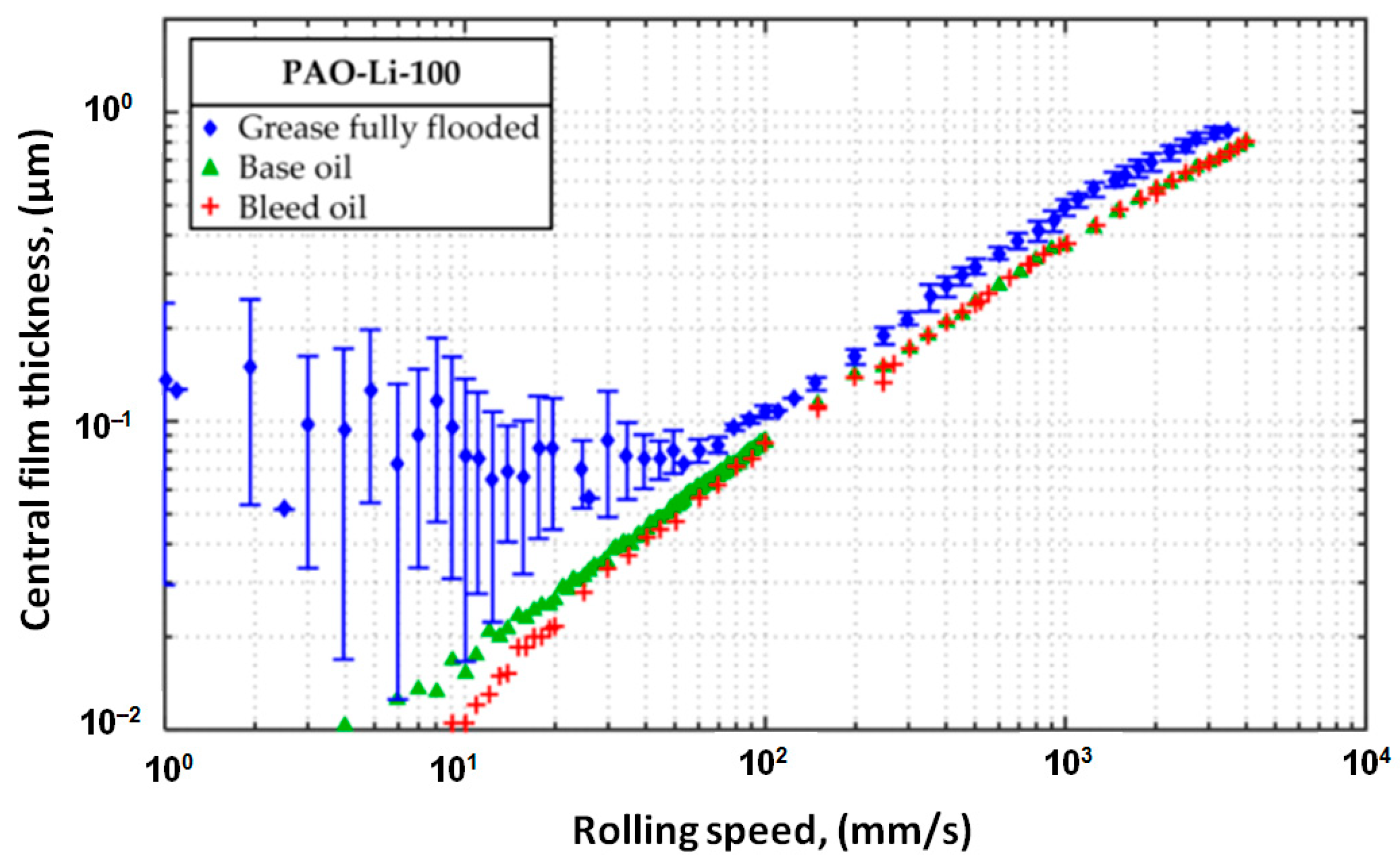
By removing the grease on the sides and creating a channel on the raceways, the film thickness decreases according to EHL theory and is dominated by the bleed oil. Increasing speed leads to an increase in the bleed oil film thickness due to hydrodynamic effects. This particular behavior of the grease film thickness is referred to as “V-shape pattern”.
Therefore, beyond a certain speed, the grease film thickness can be approximated by the thickness calculated for the base oil. While this grease film behavior (“V-shape pattern”) can be easily observed in ball-on-glass-disc contacts using optical interferometry, investigation of the grease film thickness behavior as a function of rotational speed in a ball bearing is more complex.
Some researchers used methods based on the electrical capacitance or electrical resistance of the contacts between the balls and the raceways. It has been found that the bearing’s electrical resistance increases due to the presence of a thin insulating layer formed by the oil and soap film. Several experimental studies involving electrical resistance measurements conducted by Cen et al. [7], Zhang et al. [8], Shetty et al. [9], Nagata [10], Cann [11], Maruyama et al. [12] have highlighted an increase in electrical resistance with increasing grease film thickness in rolling bearings.
A simpler but illustrative case is presented by Maruyama et al. [12], who determined the lubricant film thickness in two miniature 608-series ball bearings loaded purely axially. Across a speed range of 100 to 2000 rpm, the authors found a good correlation between increased electrical resistance and increased lubricant film thickness.
Cojocaru et al. [13] measured the electrical resistance of the 7000C angular contact ball bearing lubricated both with oil and grease at inner ring speeds from 1 to 500 rpm. The results confirmed the presence of a “V-shape pattern” for grease lubrication observable only through the variation of the ball bearing’s electrical resistance that was monitored over the speed range.
In this paper, the authors studied the grease behavior in a ball bearing determined using the electrical resistance method. The variation of the average central film thickness with the rolling speed between balls and races has been highlighted and the “V-shape pattern” was obtained for both the electrical resistance and the average central grease film thickness in balls-race contacts, respectively. Also, the authors investigated the behavior of the grease film thickness to determine whether if the starvation phenomenon occurs for extended running periods by monitoring the electrical resistance over 8 h at operating speeds between 200 and 1500 rpm. Additionally, the fresh and stressed grease structure was compared using scanning electron microscope to reveal the fragmentation of the soap filaments.

2. Experimental Equipment and Procedure

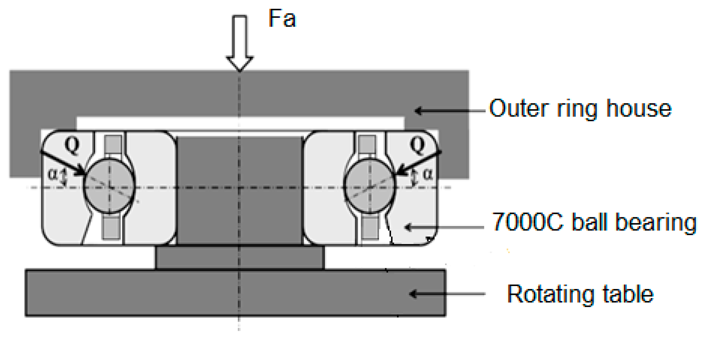
The presence of the lubricant film between the balls and the raceways when specific grease is used for lubrication was investigated by monitoring the bearing’s electrical resistance on the CETR UMT-2 Tribometer (Center for Tribology, Inc., Campbell, CA, USA). A 7000C angular contact ball bearing was mounted on the rotational table of the Tribometer. The outer ring was fixed in a cylindrical house and electrically isolated from the rest of the test rig and connected to the electrical circuit of the rig, together with the rotating table that is mechanically linked to the inner ring, as shown in Figure 1. A small axial force was applied to the housing and the outer ring of the bearing using the Tribometer force sensor to maintain the temperature within reasonable limits (27–30) °C.
Since the known relationships for determining lubricant film thickness in the ball bearings are based on the oil viscosity, the lubricant film thickness variations were calculated for a given oil at different rotational speeds, along with the corresponding electrical resistance values in the ball bearing. Based on these determinations, a quantitative correlation between the average central oil film thicknesses at the ball–raceway contacts and the overall electrical resistances of the bearing was established.
The correlation between the calculated average oil film thicknesses and the measured electrical resistances was also applied to the electrical resistance of the ball bearing measured when grease was used instead of oil. Thus, an estimation of the lubricant film thickness for the grease-lubricated ball bearing behavior was obtained.
Figure 1 shows the UMT-2 Tribometer equipped with the mounted rotating table, the force sensor applying axial load to the bearing, and the monitor connected to the central processing unit. The figure also shows the graphite contact connection system used to link the rotating table and the fixture holding the bearing’s outer ring to the electrical resistance measuring equipment of the Tribometer. In this way, the monitor displays the variation of the bearing’s electrical resistance over time.
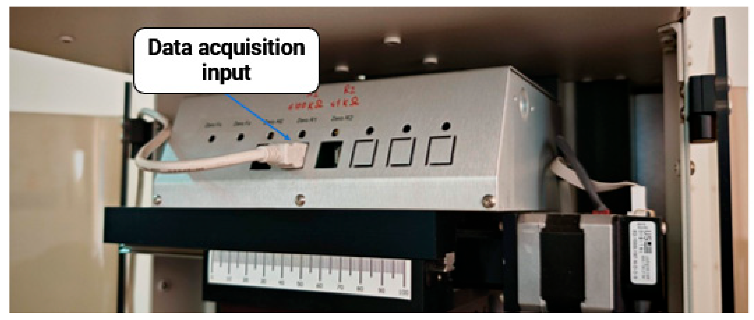
To monitor the electrical resistance, the R1 input of the Tribometer was used for data acquisition, as shown in Figure 2.
In order to compensate the variation of the electrical resistance during the measurements, it was necessary to introduce a device with a graphite element, which was placed in contact with rotating disc connected to the inner ring of the bearing. A detail of the contact device with the rotating disc is presented in Figure 3.
The electrical resistance, expressed in kΩ, is real-time displayed on the computer screen for different rotational speeds. The rotational speed of the inner ring ranges from 1 rpm to 1500 rpm when the ball bearing is lubricated with Shell Helix Hx8 5W-30 oil (Shell Company, London, UK) and from 1 rpm to 500 rpm for Shell Gadus S2 V100 2 grease (Shell Company, London, UK). The duration of each test was 60 s.
The ball bearing was loaded with a total axial force of 13.11 N consisting of the normal load applied by the tribometer (10 N) and the weight of the outer ring housing. Figure 4 presents the detailed mounting of the 7000C angular contact ball bearing on the rotating table.
According to the ball bearing geometry and neglecting the balls’ centrifugal forces, the normal load (Q) on each ball-race contact was determined using the relation:
Q   =   F a Z · sin ( α )
where α is the real contact angle obtained under the action of the axial load Fa. If initial contact angle αo = 15°, under the load of 13.11 N the real contact angle increases to α = 16.053°. The value of the normal contact load was Q = 5.926 N.
According to the ball bearing geometry, the normal contact load Q leads to a maximum normal Hertzian stress of σmax,o = 562.7 MPa at the outer ball–race contacts and σmax,i = 708.8 MPa at the inner ball–race contacts. The temperature of the rolling bearing during experiments varied within the range (27–30) °C.
The properties of the oil and the grease tested are listed in Table 1 and Table 2, respectively. The dimensional characteristics of the 7000C angular contact ball bearing are presented in Table 3.

3. Experimental Results to Demonstrate the “V-Shape Pattern”

3.1. Determination of the Variation of Electrical Resistance with Rotational Speed

The experimental tests were carried out on both oil- and grease-lubricated ball bearings and the variation in the electrical resistance with the rotational speed was determined.
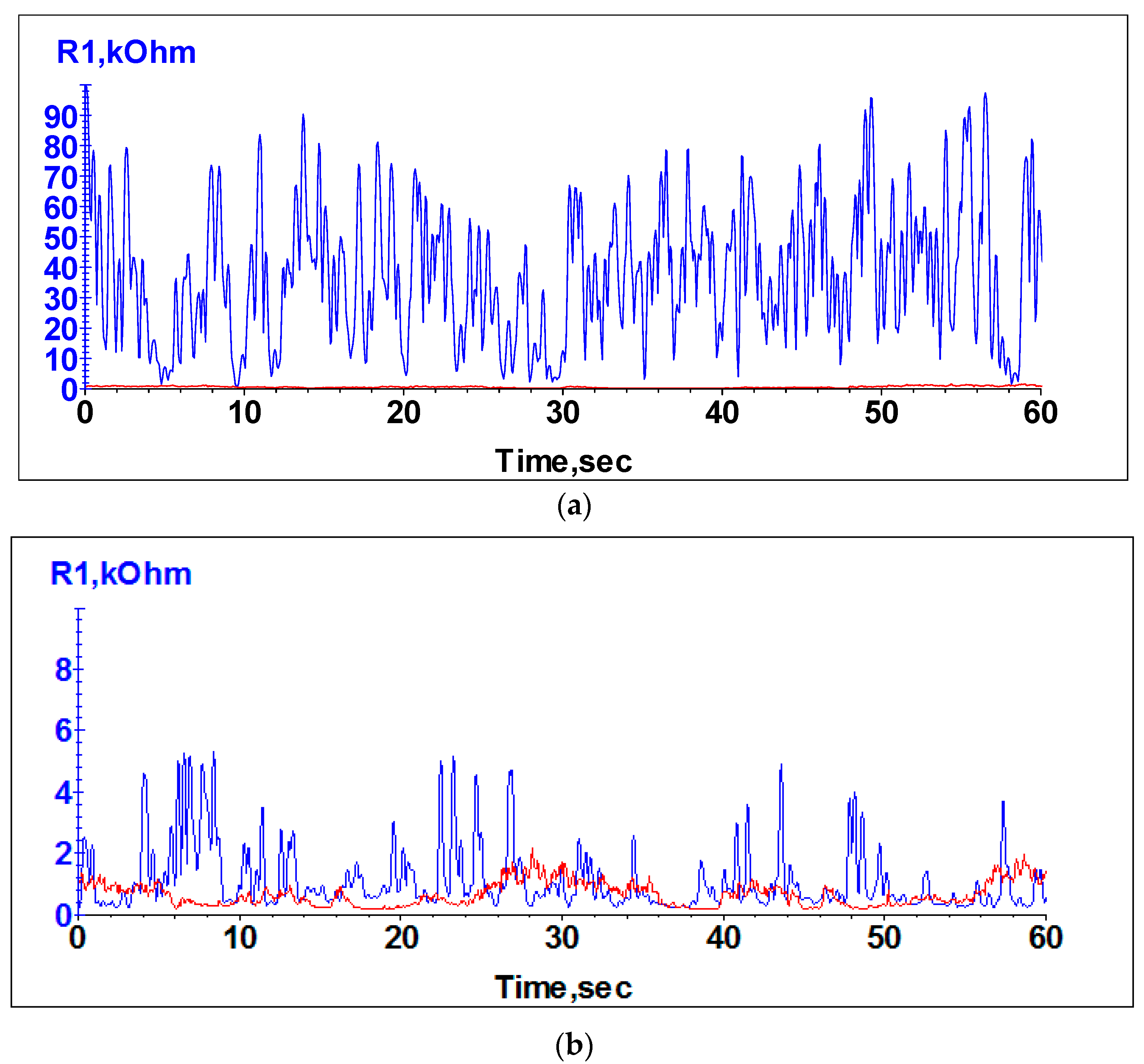
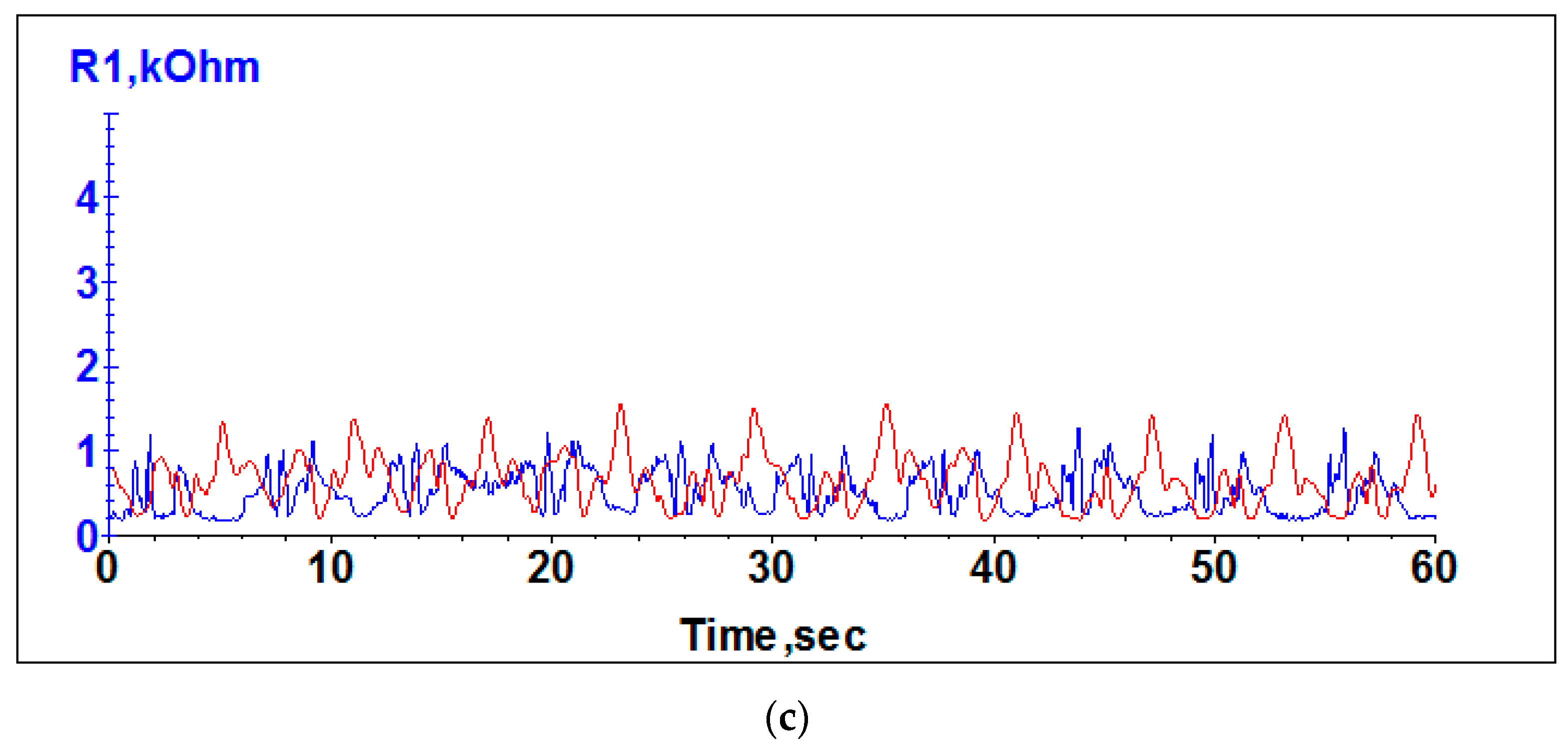
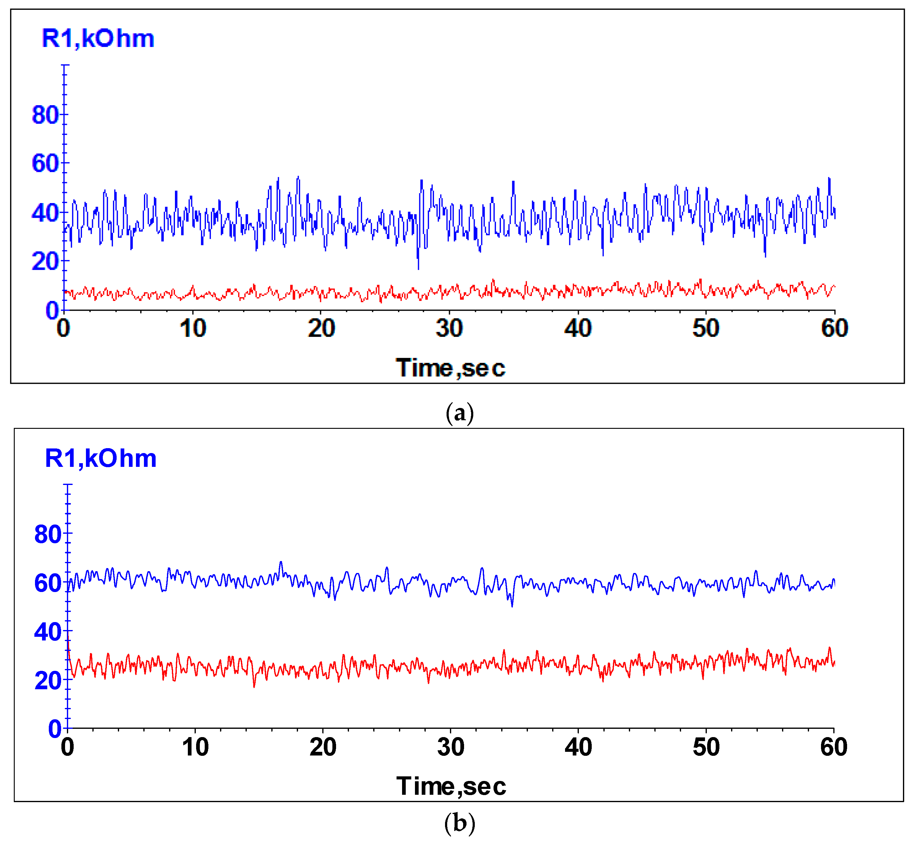
In Figure 5, the cumulative variations in electrical resistance for Shell Gadus S2 V100 2 grease and Shell Helix Hx8 5W-30 oil are presented at low rotational speeds of 1, 5 and 10 rpm, respectively. At a very low rotational speed of 1 rpm (Figure 5a), the electrical resistance of the grease-lubricated ball bearing shows large fluctuations and an average value around 40 kΩ. On the other side, the electrical resistance of the oil-lubricated ball bearing is not fluctuating, and the values are near to zero with an average of 0.3 kΩ. By increasing the rotational speed up to 10 rpm, a significant decreasing in electrical resistance of the grease-lubricated ball bearing was observed (Figure 5c). Also, the electrical resistance for the oil-lubricated ball bearing showed a slight increase. The large fluctuations of the electrical resistance observed in Figure 5 occurs due to the lubrication regime established at low rotational speeds, such as boundary and mixed regimes.
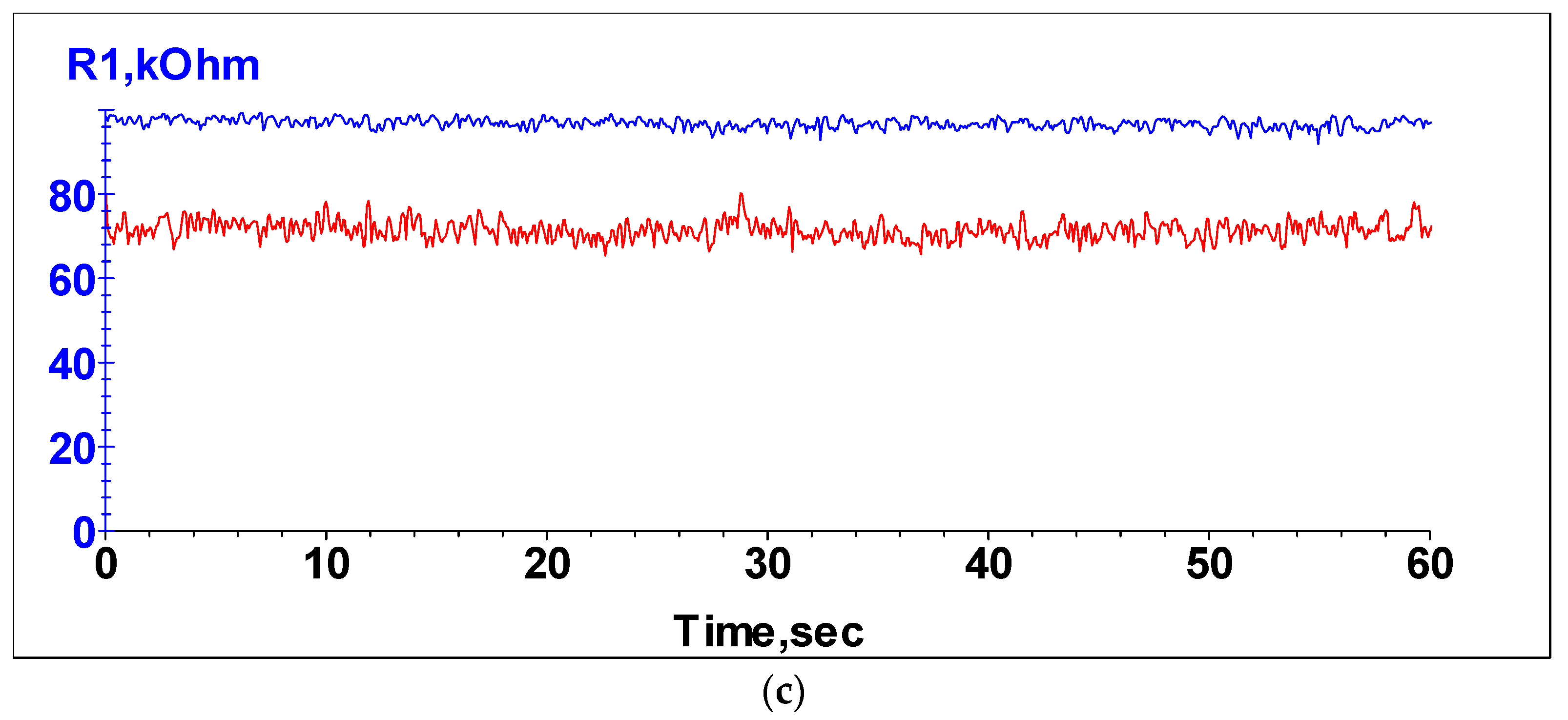
Increasing the rotational speed up to 500 rpm leads to increasing the electrical resistance for both the grease- and oil-lubricated ball bearings, as shown in Figure 6. The average value of the electrical resistance for grease-lubricated ball bearing increases from 40 kΩ to 90 kΩ for 100 rpm and 500 rpm, respectively. For oil-lubricated ball bearing the electrical resistance showed to increase from 10 kΩ to 70 kΩ for 100 rpm and 500 rpm, respectively.
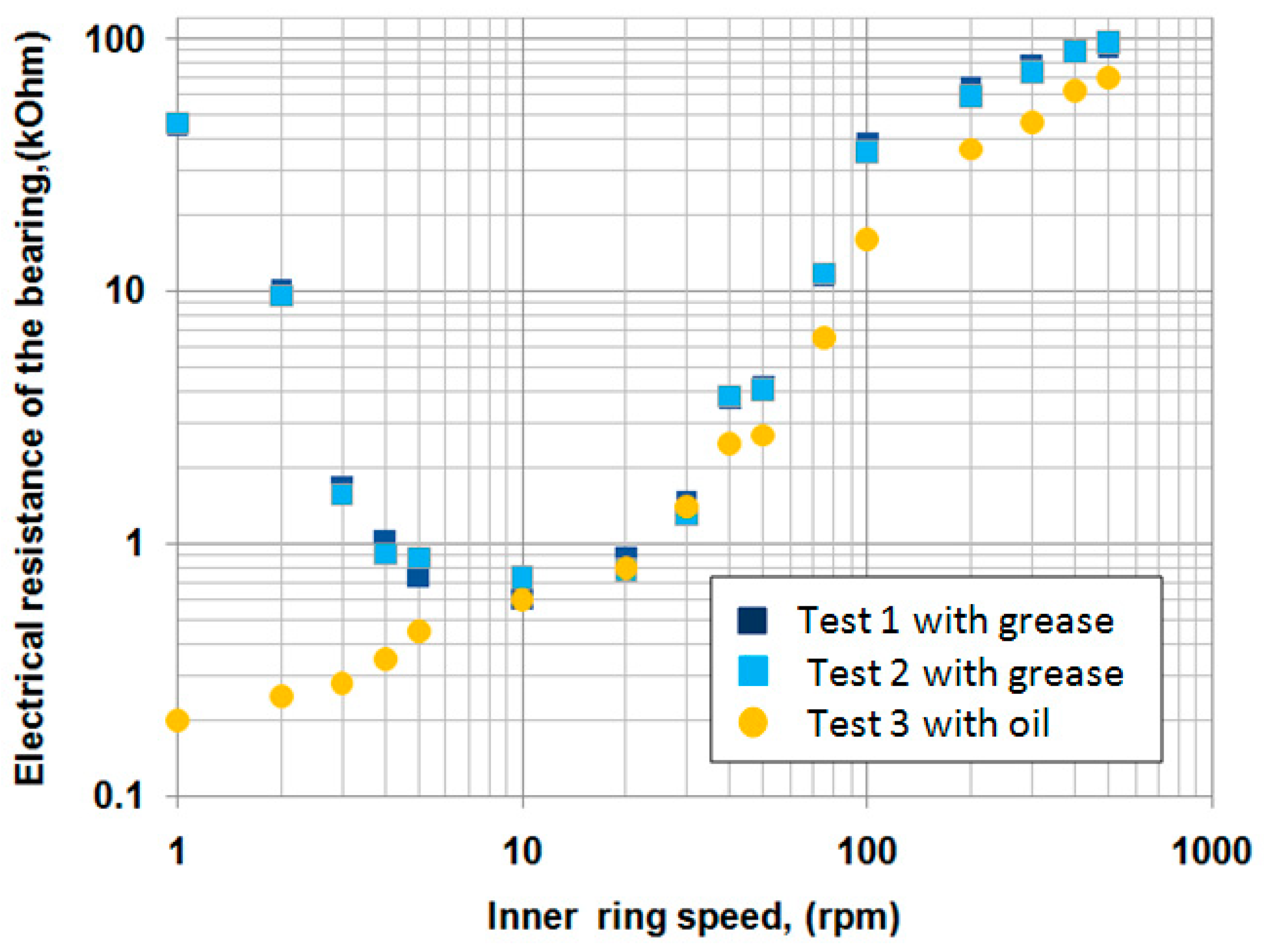
Considering the average values of the electrical resistances obtained over the entire rotational speed range from 1 to 500 rpm, in Figure 7 is illustrated the so-called “V-shape pattern” for both grease- and oil-lubricated ball bearing. Thus, considering that high electrical resistance also means a thicker lubricant film, the diagram obtained is similar to those reported in the literature regarding grease film thickness variations measured by optical interferometry [1,3,4,5].

3.2. Correlation Between Calculated Oil Film Thickness and Measured Electrical Resistance

The correlation between the electrical resistances of the ball bearing lubricated with Shell Helix Hx8 5W-30 oil and the average film thickness in the central area of the ball-raceway contacts was established through three sets of tests. The central film thicknesses for the inner and outer ball–raceway contacts were calculated for the EHL lubrication regime according to the Hamrock-Dowson equation [2]:
h c , i , o   =   2.69 · R x , i , o · U i , o 0.67 · G 0.53 · W i , o 0.067 · 1 0.61 · e 0.73 · k i , o
where Rx,i,o are reduced radii of curvature in the rolling direction for ball-inner and ball-outer raceways contacts, ki,o are the ellipticity parameter, Ui,o, G and Wi,o are the dimensionless speed, material and load parameters, respectively, determined for inner and outer contacts by relations:
U i , o   =   η o · v E * · R x , i , o G   =   α p · E * W i , o   =   Q E * · R x , i , o 2
where ηo is the dynamic viscosity, v is the tangential speed, E* is the equivalent Young’s modulus of the two elements in contact and αp is the piezo-viscous parameter.
Average central film thickness was determined by relation:
h c   =   h c , i + h c , o 2
Details of the oil characteristics at operating temperature for both Shell Helix Hx8 5W-30 oil, and the grease base oil are presented in Appendix A.
Details of the calculations for the central film thickness in the ball-inner and the ball-outer raceway contacts (hc,i and hc,o), for both oils are presented in Appendix B.
The electrical resistance of the oil-lubricated ball bearing was measured at rotational speeds between 1 and 1500 rpm.
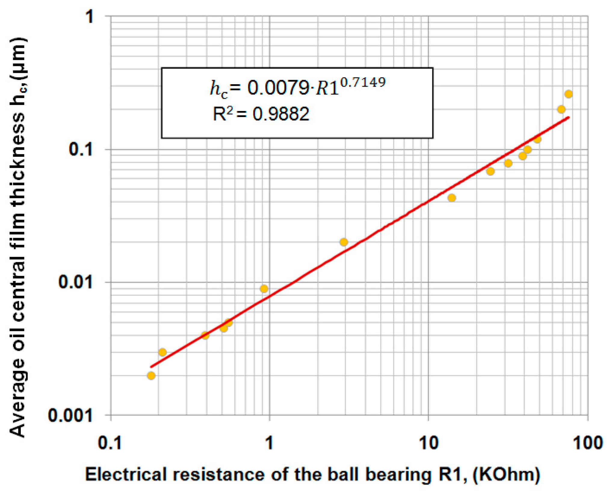
Figure 8 presents, in double logarithmic coordinates, the correlation between the measured electrical resistances of the Shell Helix Hx8 5W-30 oil-lubricated ball bearing and the average of oil film thickness in the central area of the ball–raceway contacts.
By fitting the results, an exponential correlation was obtained expressed by the following relation:
h c   =   0.0079 · R 1 0.7149   [ μ m ]
where h c represents the average thickness of the oil film in the central area of the contacts between the balls and the two raceways, and R1 represents the measured resistance of the ball bearing expressed in kΩ.
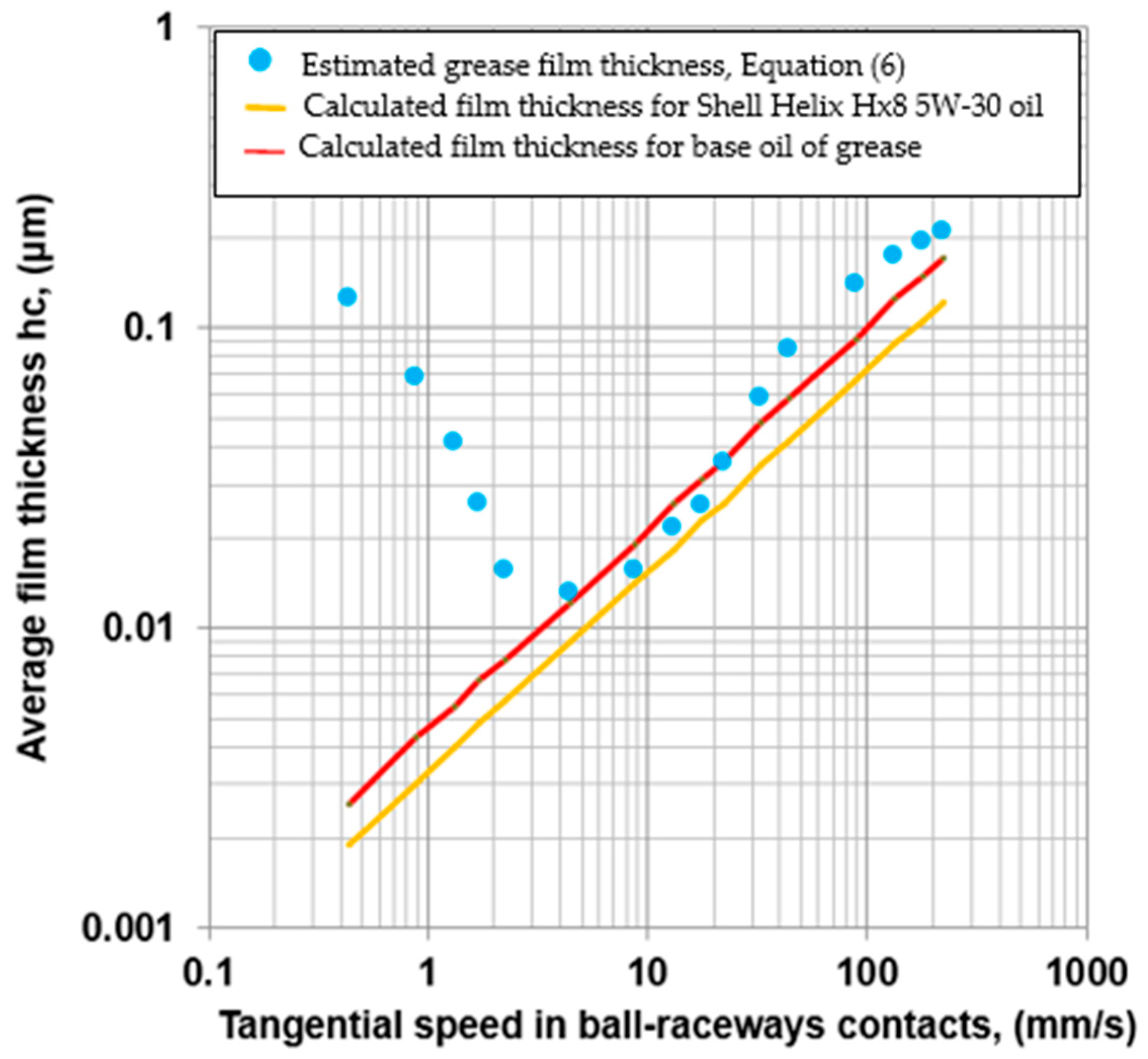
Considering that the electrical resistance in the ball bearing is dictated by the degree of separation of the contacts between the balls and the raceways, both for oil and grease, in Figure 9 is presented the variation of the grease film thickness obtained according to Equation (6), as function on the inner ring speed. Moreover, in Figure 9 is presented the calculated film thickness for both Shell Helix Hx8 5W-30 oil and grease base oil, according to the results calculated in the Appendix B.
In an angular contact ball bearing, considering pure rolling kinematics, the tangential speed v in rolling direction both in ball–inner race and ball–outer race contacts can be approximated by the Harris’ relation [14]:
v   =   π · n · d m 120 · ( 1 γ 2 )
where n is the rotational speed of the inner ring expressed in rpm, dm is the average diameter of the ball bearing and γ is a dimensionless angular parameter.
Replacing the inner ring speeds with the tangential speeds between the balls and the raceways obtained by Equation (7), the variation in the average central film thickness both for grease and the two oils as a function of the tangential ball–race speeds was obtained and is presented in Figure 10.
The grease film thickness was shown to decrease at very low tangential speeds (0.3–0.4 mm/s) up to about 5 mm/s and then increases with speed exceeding the Shell Helix Hx8 5W-30 oil film thickness.
The “V-shape pattern” distribution of the grease film thickness with speed illustrated in Figure 10 is similar to the model reported by Fischer et al. [1], which is presented in Figure 11. Fischer et al. [1] obtained the results by interferometry method in a ball-on-glass disc tribometer using a polyalphaolephin lithium complex grease (PAO-Li-100), with a base oil viscosity of 98.01 mm2/s at 40 °C and 22.14 mm2/s at 80 °C.
As a conclusion, by using the electrical resistance measurement method over a range of rotational speeds from 1 rpm to 500 rpm, the authors obtained the “V-shape pattern” behavior of the grease film thickness. For the tangential speeds higher than 40 mm/s the average grease film thicknesses exceeds the values of the average Shell Helix Hx8 5W-30 oil film thicknesses with 25% to 35% higher compared to the literature [1,3,4,5]. It can be explained by the difference in the viscosity of Shell Helix Hx8 5W-30 oil and grease base oil. By comparing the estimated grease film thickness with the calculated base oil film thickness, the differences are lowered to (15–25)%. Therefore, the authors consider that the higher differences between the evaluated grease film thickness and oil film thickness obtained by electrical resistance methodology is due to the differences in viscosity between the oil tested and the grease base oil. Considering the experimental temperature range of (27–30) °C, the viscosity of the Shell Gadus S2 V100 2 grease base oil and the Shell Helix Hx8 5W-30 oil were (213.5–176.8) mm2/s and (114.2–94.2) mm2/s, respectively. These differences in viscosities leads to an increase in the base oil film thickness by approx. 25% compared to the oil tested. Also, possible differences in the resistivity between the oil film thickness and the oil film with supplementary adhered thin soap film can be considered.

4. Determination of the Grease Film Stability

Cen et al. [7] evidenced three phases in the evolution of grease film thickness as a function of the running time. Thus, in the first phase after introducing the grease into the ball bearing, the excess grease is gradually expelled from the sides. In this phase, the film thickness is higher than the base oil film thickness determined with EHL models. In the second phase, the bleed oil ensures the supply of the ball–raceway contacts, leading to the formation of an EHL film thickness. Depending on the rotational speed, the time between two successive passes of the balls over the raceway may be shorter than the refill time of the track with bleed oil, potentially leading to starvation phenomenon. The bleed oil feed rate of the raceway is a complex phenomenon. P. Lugt [15] highlights several contributing factors including grease rheology, shear degradation and the amount of grease on the sides. The third phase involves the loss of lubricating capacity of the grease with a severe reduction in film thickness and increase in bearing temperature.
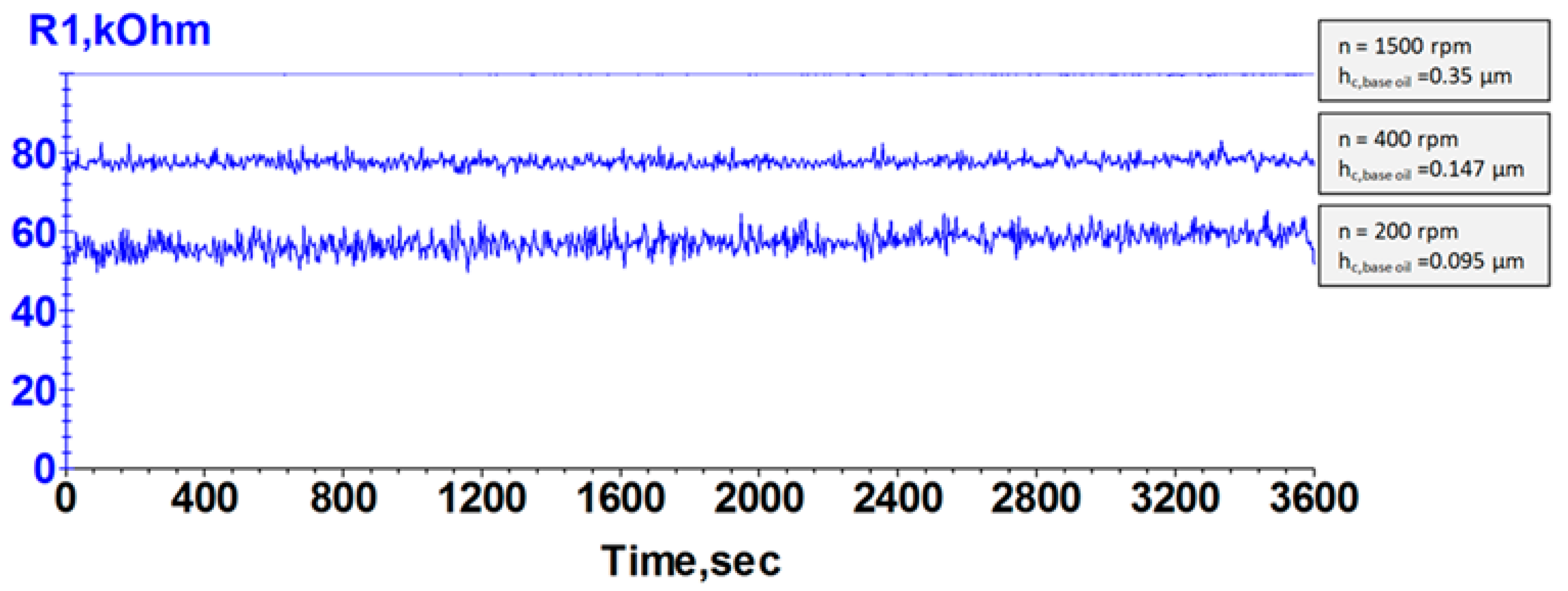
In this study, the authors evaluated the stability of the grease film thickness generated at 8 different rotational speeds between 200 rpm and 1500 rpm by monitoring the variations in ball bearing electrical resistance for 60 min at each speed. To prevent excessive temperature rise, the initial amount of fresh grease was about 0.15 cm3, evenly distributed on both raceways. Figure 12 presents the variation of the electrical resistance at three rotational speeds of 200, 400 and 1500 rpm. For each rotational speed, the average central film thickness of the grease base oil is highlighted.
From Figure 12 it can be observed that for each rotational speed no significant variation in electrical resistance was observed on a period of 60 min, revealing a good stability of the grease lubrication. The average lubricant parameter Λ can be determined by:
Λ   =   h c R q r 2 + R q b 2
The lubricant parameter Λ calculated with the average central film thickness of base oil have values of 1.35 and 2.5 for the rotational speed of 200 and 500 rpm, respectively, indicating a mixed lubrication regime. Increasing the rotational speed over 700 rpm it can be obtained fully flooded lubrication conditions (Λ > 3) such as Λ = 3.9 and Λ = 5.22 at 1000 rpm and 1500 rpm, respectively.
It can be noticed that during the entire 8 h of operation at different rotational speeds, no grease starvation phenomenon was observed. The starvation phenomenon occurs when the time between two successive balls is less than the time it takes to refill the track left by the balls.
The time between two successive balls for the rotational speed between 200 and 1500 rpm was determined according to the Harris’ relation [14]:
t i , o = 120 Z · n · ( 1 ± γ )     [ s ]
where the sign (+) is for inner race and sign (−) is for outer race.
The time between two successive balls calculated with Equation (9) ranges between 0.06 and 0.09 seconds for 200 rpm and 0.008 and 0.01 seconds for 1500 rpm, respectively. By correlating these values with the electrical resistance measurements, it suggests that the refill time is shorter than the interval between two successive ball passes.
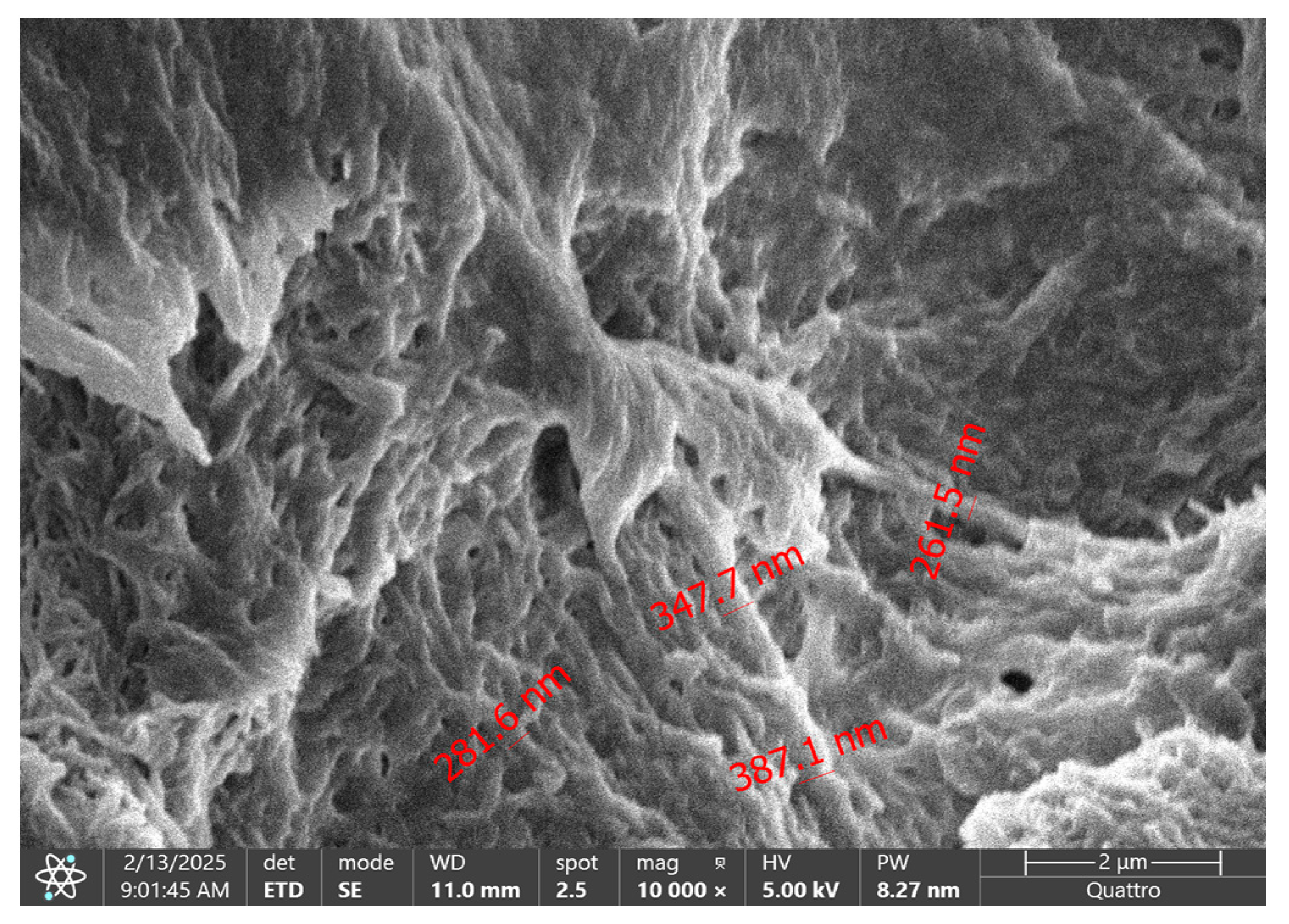
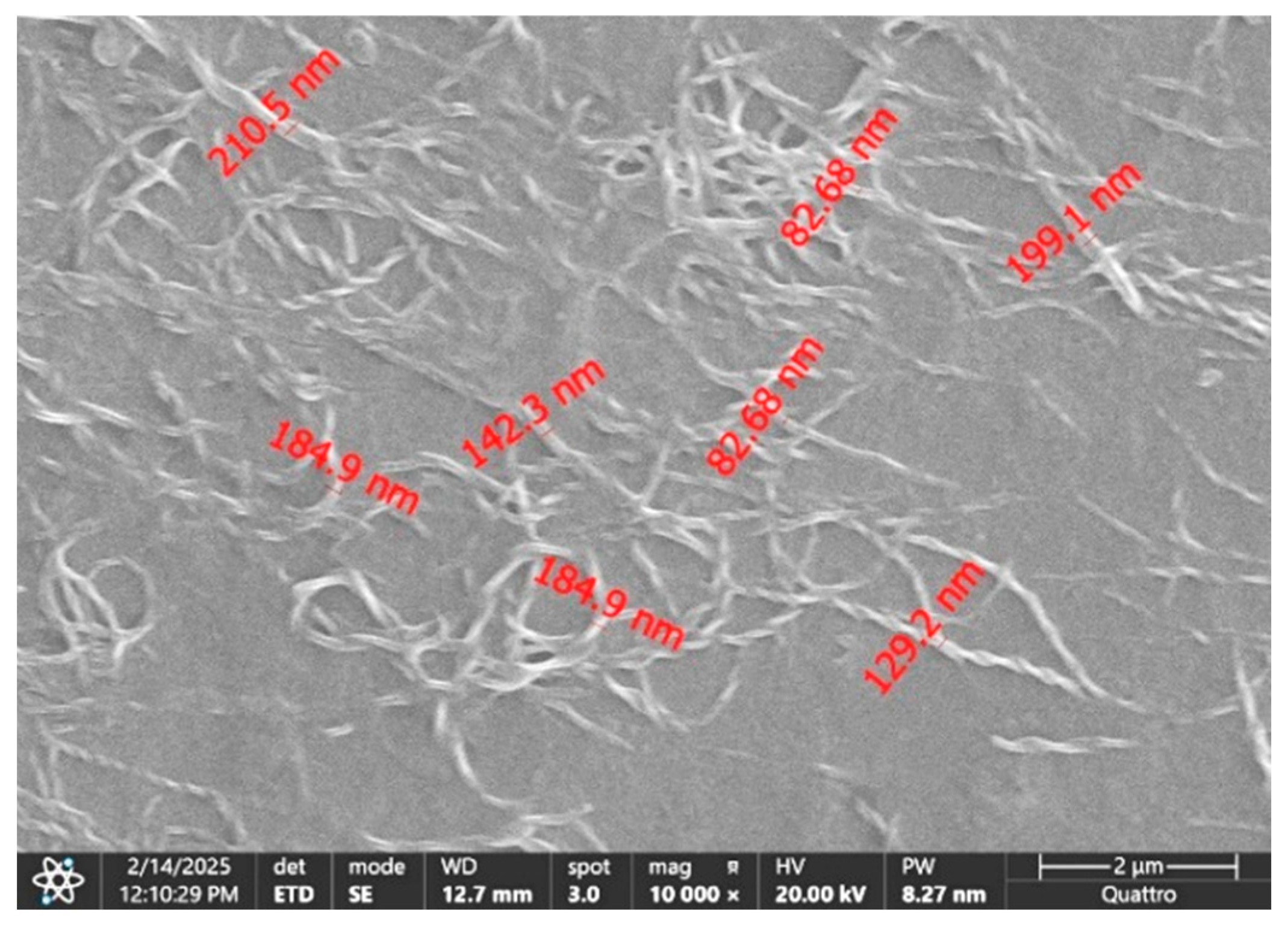
Moreover, to highlight any changes in the grease microstructure, samples of the fresh and stressed grease after 8 operating hours were analyzed using the scanning electron microscopy (SEM) Quattro C (Thermo Fisher Scientific, Brno, Czech Republic). Figure 13 presents the fresh grease microstructure at a magnification of 10,000×.
Figure 14 presents the stressed microstructure of the grease on the racetrack after 8 h of operating at speeds between 200 and 1500 rpm. Some minor fragmentation of the soap filaments can be observed, caused by the normal and shear stresses in ball–race contacts. Since lubrication is provided by the bleed oil from the sides that were not subjected to ball–race stresses, the minor fragmentations observed did not negatively affect lubrication even at 1500 rpm.

5. Conclusions

The authors concluded the following:
  • The behavior of the average grease-lubricated film thickness in an angular contact ball bearing is consistent with the results obtained by interferometry for a single ball–glass disc grease-lubricated contacts reported in the literature.
  • At low rotational speeds of the ball bearing, the so-called “V-shape pattern” behavior of the grease film thickness was obtained with a maximum value at 1 rpm and minimum value around 10 rpm.
  • At rotational speeds between 100 and 500 rpm, the average grease film thickness increase was similar to the average base oil film thickness and exceed the average base oil film thickness with (15–25)%. The “V-shape pattern” and the results obtained by the authors are in good agreement with those reported by Fischer et al. [1], both in terms of film thickness and the tangential speeds.
  • The stability of the grease film thickness at eight different rotational speeds between 200 rpm and 1500 rpm was demonstrated by the constant electrical resistance for a period of 60 min for each rotational speed.
  • For rotational speeds between 200 rpm and 1500 rpm, the average lubricant parameters Λ calculated with the grease base oil varied between 1.35 and 5.22, indicating both mixed and fully flooded lubrication conditions.
  • The time between two successive balls for the rotational speed between 200 and 1500 rpm was determined, and it was concluded that the time for bleed oil to refill the track left by the balls is less than the time between two successive ball passes, explaining the absence of the starvation phenomenon.
  • Using scanning electron microscopy (SEM), the fresh and stressed grease microstructure was investigated, revealing minor fragmentations of the soap filaments after 8 h of operating at various rotational speeds.

Author Contributions

Conceptualization, D.C., G.I., V.C., B.C. and D.O.; methodology, D.C., V.C., G.I. and D.O.; software D.C., V.C. and B.C.; validation, G.I. and D.O.; formal analysis; investigation; resources, D.C., G.I., V.C., B.C. and D.O.; data curation, D.O.; writing—original draft preparation, D.C., G.I. and D.O.; writing—review and editing, D.C., G.I., V.C., B.C. and D.O.; visualization, D.O.; supervision, D.O. All authors have read and agreed to the published version of the manuscript.

Funding

This research received no external funding.

Data Availability Statement

The original contributions presented in this study are included in the article. Further inquiries can be directed to the corresponding author.

Acknowledgments

This paper was supported by Mechanical Engineering Doctoral School of “Gheorghe Asachi” Technical University of Iaşi.

Conflicts of Interest

The authors declare no conflict of interest.

Abbreviations

The following abbreviations are used in this manuscript:
dbball diameter [m]
dmaverage diameter of ball bearing [m]
ki,oellipticity parameter [dimensionless]
fi,oinner and outer race conformity [dimensionless]
hcaverage central film thickness [µm]
nrotational speed of the inner race [min−1]
vaverage entrainment speed in ball-race contacts [ms−1]
E*equivalent Young’s modulus of the two elements in contact [Pa]
Faaxial load acting of the ball bearing [N]
Qnormal load in ball-race contact [N]
Rx,i,oreduced radii of curvature in the rolling direction [m]
Ry,i,oreduced radii of curvature in the transverse direction [m]
Znumber of the balls [dimensionless]
αcontact angle of the ball bearing [degrees]
αppiezo-viscous parameter of lubricant [Pa−1]
γangular contact ball bearing parameter [dimensionless]
ηodynamic viscosity of base oil for grease [Pa·s]
Λlubricant parameter [dimensionless]

Appendix A. Determination of the Oils Characteristics at Operating Temperature

Appendix A.1. Determination of the Oil Viscosity at a Given Temperature

Based on the Walther equation, Khonsary and Booster [16] proposed following relations to determine the oil viscosity at an imposed temperature.
The Walther equation is:
log(log(ν + 0.7) = AB·log(T °C + 273.1)
where A and B are constants for any given oil, and ν is kinematic viscosity at a given temperature expressed in °C (usually 40 °C and 100 °C).
If the kinematic viscosity ν is expresses in mm2/s and is known at 40 °C and at 100 °C, Equation (A1) permit to determine the constants A and B.
Considering the kinematic viscosity for Shell Helix Hx8 5W-30 oil indicated in the Table 1, the values of the constants A and B results from solving following two equations:
log(log(61.7 + 0.7) = AB·log(40 + 273.1)
log(log(11 + 0.7) = AB·log(100 + 273.1)
Solving above two equations it obtained: A = 7.644 and B = 2.961.
Using Equation (A1), the oil viscosity was determined ν = 114 mm2/s and ν = 94.2 mm2/s at 27 °C and 30 °C, respectively.
For base oil of the grease Shell Gadus S2 V100 2 the kinematic viscosities are indicated in the Table 2 and following two equations results:
log(log(100 + 0.7) = AB·log(40 + 273.1)
log(log(11 + 0.7) = AB·log(100 + 273.1)
Solving the Equations (A4) and (A5) results A = 9.251 and B = 3.586.
Using Equation (A1), the base oil viscosity was determined ν = 213.5 mm2/s and ν = 176.8 mm2/s at 27 °C and 30 °C, respectively.

Appendix A.2. Determination of the Piezo-Viscosity Coefficients for Oils

The piezo-viscosity coefficient is determined by following equation [16]:
αp = Z·[5.1 × 10⁻⁹ (ln(ηo) + 9.67)]
where ηo is the dynamic viscozity at normal pressure expressed in mPa·s and Z is the Roelands’ pressure–viscosity index.
Z = [7.81(H40H100)]1.5 (F40)
H40 = log(log(η*o,40 + 1.200)
H100 = log(log(η*o,100 + 1.200)
F40 = (0.885 − 0.864 × H40)
where η*o,40 and η*o,100 are the dynamic viscosities at 40 and 100 °C expressed in mPa·s.
Considering the two oils’ viscosities results for Shell Helix Hx8 5W-30 αp = 1.7 × 10⁻⁸ Pa−1 and for base oil of the grease αp = 1.8 × 10⁻⁸ Pa−1.

Appendix B. Determination of the Film Thickness in the Balls-Races Contacts

To evaluate the central film thickness both in ball-inner and ball-outer raceways Hamrock-Dowson equation has been used [2]:
h c , i , o   =   2.69 · R x , i , o · U i , o 0.67 · G 0.53 · W i , o 0.067 · 1 0.61 · e 0.73 · k i , o
where Ui,o, G and Wi,o are the dimensionless speed, material and load parameters, respectively, determined for inner and outer contacts by relations:
U i , o   =   η o · v E * · R x , i , o
G = α p · E *
W i , o = Q E * · R x , i , o 2
In the speed parameter U, ηo is the oil viscosity at operating temperature, expressed in Pa·s.
Tangential speed in the rolling direction v is determined considering pure rolling between balls and two raceways. Based on the simple kinematics in an angular contact ball bearing, tangential speeds on outer and inner contacts are the same values determined by relation [14]:
ν   =   π · n · d m 120 · 1 γ 2
where n is rotational speed of inner ring in rpm, dm is average diameter of ball bearing determined with relation: dm = (d + D)/2 and is expressed in [m].
Dimensionless parameter γ is determined by relation:
γ   =   d b · cos α / d m
where db is ball diameter.
E* is equivalent Young’s modulus in balls-races contacts. For steel-on-steel contact, a value of 2.26 × 10¹¹ Pa usually is accepted.
Rx,i,o are reduced radii of curvature in the rolling direction for ball-inner and ball-outer raceways contacts, respectively. The reduced radii can be determined by following relations:
For inner race contact:
R x , i   =   d b 2 · 1 γ
For outer race contact:
R x , o   =   d b 2 · ( 1   +   γ )
Dimensionless material parameter G include the piezo-viscosity exponent αp, depending on the oil viscosity and is expressed in Pa−1.
Load dimensionless parameter W include normal load on the ball-race contact, Q expressed in N.
For an angular contact ball bearing, the contact load Q is determined by relation:
Q   =   F a Z * sin   α
where Fa is the axial force acting on the ball bearing, Z is the number of the balls and α is real contact angle after loaded.
The real contact angle increases by increases the axial load. In our experimental conditions, for an axial load of 13.11 N we calculated the real contact angle using Harris methodology [15]. If initial contact angle αo = 15°, under the load of 13.11 N the real contact angle increases to value of α = 16.053°, that means a value for axial load of Q = 5.926 N.
Also, at high speed the inner and outer contact angle has different values as result of effect of centrifugal force generated by the balls centrifugal force. For the tested miniature angular contact ball bearing 7000C, the ball diameter is 4.762 mm and centrifugal force at 600 rpm is 0.006 N and at 1500 rpm is 0.039 N while the normal force Q = 5.926 N.
If centrifugal force does not exceed 6% from the normal load in the range of rotational speeds, can be neglected.
The dimensionless ellipticity parameter ki,o are determined with following relation [2]:
k i , o   =   1.03 · R y , i , o R x , i , o 0.64
where Ry is the reduced radii of curvature in the transverse direction. For an angular contact ball bearing, Ry is determined by relations:
for inner race contact
R y , i = d b · f i ( 2 · f i 1 )
for outer race contact
R y , o = d b · f o ( 2 · f o 1 )
where fi and fo are the ball-races conformities for inner and outer contacts as ratio between curvature radius of raceways and ball diameter [14].
For a pure axially loaded, all the outer and inner balls-races contacts have the same normal load which allows us to consider that at all contacts between the balls and inner raceways there will be the same film thickness as at the outer balls and raceways contacts. Since the film thickness differences on the two raceways vary slightly in magnitude, an average film thickness hc will be used.
In Table 1 and Table 2 are presented the viscosities at 40 °C and 100 °C for the oil Shell Helix Hx8 5W-30 and for the base oil of the grease Shell Gadus S2 V100 2. In Appendix A.1 is presented the Khonsary’s methodology to estimate the viscosity at operating temperature for both oils and to determine the piezo-viscosity coefficient for both oils at operating temperature.

Appendix B.1. Average Central Film Thickness for Shell Helix Hx8 5W-30
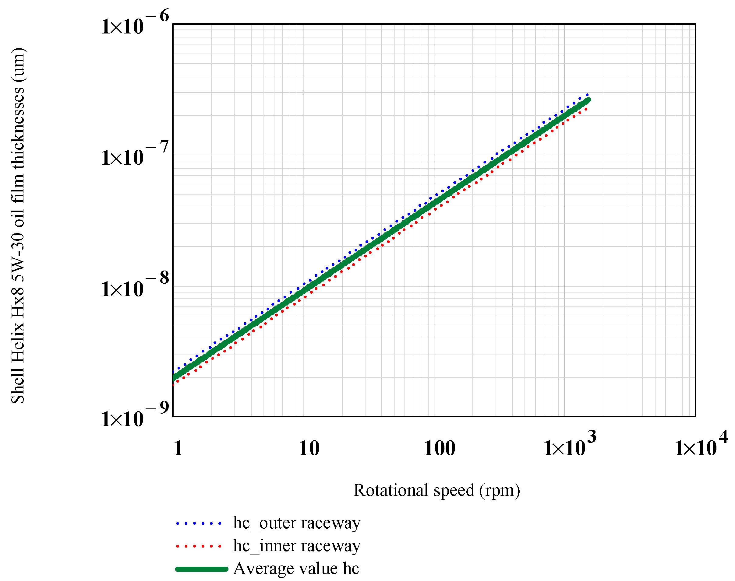
For a density of ρ = 850 kg/m3 the dynamic viscosity at 27 °C is ηo = 0.0935 Pa·s. Also, the piezo-viscosity αp = 1.7 × 10⁻⁸ Pa−1.The central film thicknesses on the inner and outer raceways, hc,i and hc,o are presented in the logarithmic diagram as function of the rotational speed on Figure A1. In the same figure is presented also, the average film thickness hc = (hci + hco)/2.
Figure A1. The central film thicknesses on the inner raceway, outer raceway and average film thickness for Shell Helix Hx8 5W-30 oil.
Lubricants 13 00429 g0a1

Appendix B.2. Average Central Film Thickness for Base Oil of the Grease Shell Gadus S2 V100 2

For a density of ρ = 850 kg/m3 the dynamic viscosity at 27 °C is ηo = 0.149 Pa·s. The piezo-viscosity αp = 1.8 × 10⁻⁸ Pa−1.The central film thicknesses on the inner and outer raceways, hc,i and hc,o are presented in the logarithmic diagram as function of the rotational speed on Figure A2. In the same figure is presented also, the average film thickness hc = (hci + hco)/2.
Figure A2. The central film thicknesses on the inner raceway, outer raceway and average film thickness for base oil of grease Shell Gadus S2 V100 2.
Lubricants 13 00429 g0a2

References

  1. Fischer, D.; Jacobs, G.; Stratmann, A.; Burghardt, G. Effect of base oil type in grease composition on the lubricating film formation in EHD contacts. Lubricants 2018, 6, 32. [Google Scholar] [CrossRef]
  2. Hamrock, B.J.; Dowson, D. Ball Bearing Lubrication, The Elastohydrodynamics of Elliptical Contacts; John Willey & Sons: Hoboken, NJ, USA, 1981. [Google Scholar]
  3. Cann, P.M.; Spikes, H.A. Film Thickness Measurements of Lubricating Greases Under Normally Starved Conditions. NLGI Spokesm. 1992, 56, 21–27. [Google Scholar]
  4. Cen, H.; Lugt, P.M.; Morales-Espejel, G. Film Thickness of Mechanically Worked Lubricating Grease at Very Low Speeds. Tribol. Trans. 2014, 57, 1066–1071. [Google Scholar] [CrossRef]
  5. Cen, H.; Lugt, P.M.; Morales-Espejel, G. On the Film Thickness of Grease-Lubricated Contacts at Low Speeds. Tribol. Trans. 2014, 57, 668–678. [Google Scholar] [CrossRef]
  6. Zhang, S. Calculation of the Lubricating Film Thickness in Grease-Lubricated Rolling Contacts. Ph.D. Disertation, Institute for Machine Elements and Systems Engineering (MSE) at RWTH Aachen University, Aachen, Germany, 2024. Available online: https://publications.rwth-aachen.de/record/992739/files/992739.pdf (accessed on 3 April 2025).
  7. Cen, H.; Bai, D.; Chao, Y.; Li, Y.; Li, R. EHL film thickness in rolling element bearings evaluated by electrical capacitance method: A review. In Tribology-Materials, Surfaces and Interfaces; Taylor and Francis Ltd.: Oxfordshire, UK, 2021; Volume 15, pp. 55–77. [Google Scholar]
  8. Zhang, Q.; Mugele, F.; van den Ende, D.; Lugt, P.M. A model configuration for studying stationary grease bleed in rolling bearings. Tribol. Trans. 2021, 64, 1127–1137. [Google Scholar] [CrossRef]
  9. Shetty, P.; Meijer, R.J.; Osara, J.A.; Lugt, P.M. Measuring film thickness in starved grease-lubricated ball bearings: An improved electrical capacitance method. Tribol. Trans. 2022, 65, 869–879. [Google Scholar] [CrossRef]
  10. Nagata, Y. EHD Phenomena in Grease Lubrication Contacts. Ph.D. Thesis, University of Sussex, Brighton, UK, 2011. Available online: https://sussex.figshare.com/articles/thesis/EHD_phenomena_in_grease_lubricated_contacts/23315012?file=41103371 (accessed on 28 March 2025).
  11. Cann, P.M. Grease film thickness and friction in EHL contacts. In Proceedings of the Scientific Achievements, Industrial Applications, Future Challenges, the 2nd World Tribology Congress, Vienna, Austria, 3–7 September 2001; Franek, F., Ed.; Österreichische Tribologische Gesellschaft: Wien, Austria, 2001; pp. 159–164, ISBN 3-901657-07-X. [Google Scholar]
  12. Maruyama, T.; Maeda, M.; Nakano, K. Lubrication Condition Monitoring of Practical Ball Bearings by Electrical Impedance Method. Tribol. Online 2019, 14, 327–338. [Google Scholar] [CrossRef]
  13. Cojocaru, D.; Ianuş, G.; Cârlescu, V. Film thickness în miniature ball bearing grease lubricated. IOP Conf. Ser. Mater. Sci. Eng. 2022, 1262, 012005. [Google Scholar] [CrossRef]
  14. Harris, T.A. Rolling Bearing Analysis, 4th ed.; John Willey & Sons, Inc.: Hoboken, NJ, USA, 2001. [Google Scholar]
  15. Lugt, P.M. A review on grease lubrication in rolling bearings. Tribol. Trans. 2009, 52, 470–480. [Google Scholar] [CrossRef]
  16. Khonsary, M.N.; Booser, E.R. Applied Tribology. Bearing Design and Lubrication, 3rd ed.; Wiley: Hoboken, NJ, USA, 2017. [Google Scholar]
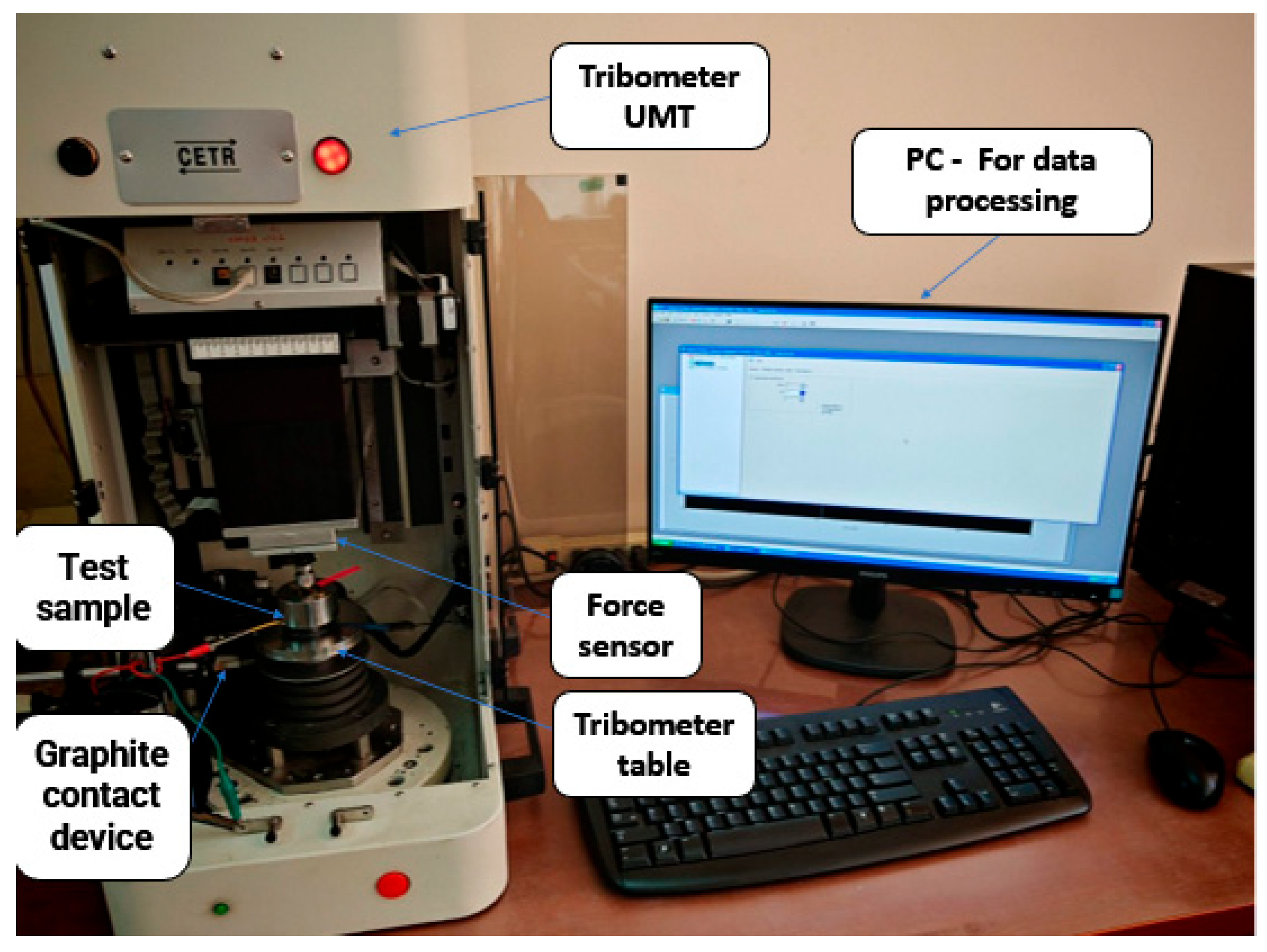
Figure 1. General view of the UMT-2 Tribometer and experimental setup for measuring the electrical resistance of the ball bearing.
Lubricants 13 00429 g001
Figure 2. The R1 input for Tribometer data acquisition.
Lubricants 13 00429 g002
Figure 3. Detail of the electrical signal collection on the rotary table graphite device.
Lubricants 13 00429 g003
Figure 4. The detailed mounting of the 7000C angular contact ball bearing on rotating table.
Lubricants 13 00429 g004
Figure 5. Electrical resistance variation with time for Shell Gadus S2 V100 2 grease (blue) and Shell Helix Hx8 5W-30 oil (red) at low rotational speeds: (a) 1 rpm; (b) 5 rpm and (c) 10 rpm.
Lubricants 13 00429 g005aLubricants 13 00429 g005b
Figure 6. Electrical resistance variation with time for Shell Gadus S2 V100 2 grease (blue) and Shell Helix Hx8 5W-30 oil (red) at medium rotational speeds: (a) 100 rpm; (b) 200 rpm and (c) 500 rpm.
Lubricants 13 00429 g006aLubricants 13 00429 g006b
Figure 7. The average electrical resistance with inner ring speed for Shell Gadus S2v100 2 grease and Shell Helix Hx8 5W-30 oil.
Lubricants 13 00429 g007
Figure 8. Correlation between the measured ball bearing electrical resistance and the average oil central film thickness in the ball-raceway contacts (yellow dots are experimental values and red line is fitting curve).
Lubricants 13 00429 g008
Figure 9. Variation of the average film thickness for Shell Gadus S2V100 2 grease, the base oil of grease and Shell Helix Hx8 5W-30 oil, as function of the inner ring speed.
Lubricants 13 00429 g009
Figure 10. The variation in the average central film thickness for grease and for the two oils, as function of the tangential ball–race speeds.
Lubricants 13 00429 g010
Figure 11. Variation of the film thickness both for grease and base oil in ball–glass disc lubricated contacts obtained by Fischer et al. [1].
Lubricants 13 00429 g011
Figure 12. Variation of ball bearing electrical resistance operating at 200, 400 and 1500 rpm.
Lubricants 13 00429 g012
Figure 13. Fresh grease microstructure at a magnification of 10,000×.
Lubricants 13 00429 g013
Figure 14. Stressed grease microstructure after 8 h of operation at a magnification of 10,000×.
Lubricants 13 00429 g014
Table 1. The properties of the Shell Helix Hx8 5W-30 oil.
PropertiesUnitsValues
Kinematic viscosity at 40 °Cmm2/s61.7
Kinematic viscosity at 100 °Cmm2/s11
Density at 15 °Ckg/m3850
Piezo-viscous parameter of base oil at 25 °CPa−12.5 × 10⁻⁸
Viscosity index 172
Table 2. The properties of the grease Shell Gadus S2 V100 2.
PropertiesUnitsValues
NLGI Consistency 2
Soap Type: Lithium Hydroxystearate
Base Oil Type: Mineral
Base oil kinematic viscosity @40 °Cmm2/s100
Base oil kinematic viscosity @100 °Cmm2/s11
Dropping point°C180
Table 3. Dimensional characteristics of the 7000C P4 ball bearing.
DimensionsValuesUnits
D—external diameter26mm
d—internal diameter10mm
dm—pitch diameter dm = (D+d)/218mm
db—ball diameter4.762mm
α—contact angle15degrees
Z—number of balls8-
fi, fo—inner and outer races conformitiesfi = fo = 0.525-
Rq,r—root mean square roughness of races0.06µm
Rq,b—root mean square roughness of balls0.03µm
Disclaimer/Publisher’s Note: The statements, opinions and data contained in all publications are solely those of the individual author(s) and contributor(s) and not of MDPI and/or the editor(s). MDPI and/or the editor(s) disclaim responsibility for any injury to people or property resulting from any ideas, methods, instructions or products referred to in the content.