1. Introduction
To enable the transition to a sustainable industry, tribological improvements will play an increasingly important role in the future. A reduction in friction and wear is directly linked to greater efficiency and material savings and thus leads to lower energy losses, material waste and air pollution. According to Ciulli [
1], this goal is currently being increasingly pursued by various tribological research areas. Holmberg and Edemir [
2] quantified the share of energy consumption due to friction and wear at around 23% of global energy consumption, although there is still considerable long-term savings potential here. There are various technical approaches to improving tribological contacts, such as the development of better and more sustainable lubricants [
3], adapting the materials used [
4], or the surface treatment of components, for example, using amorphous carbon coatings (DLC-coatings) [
5].
Another approach is the defined microtexturing of the surfaces. In addition to other positive effects, such as the inclusion of wear particles [
6], this can achieve improved frictional behavior in hydrodynamic contacts (HD) [
7] and elastohydrodynamic contacts (EHL). In the latter case, texturing can be used to technical advantage, for example, in cam tappet contacts [
8], in gear contacts [
9], or in the field of medical technology for knee [
10] or hip implants [
11]. However, since the exact shape and arrangement of the textures are decisive for the resulting friction behavior and, in the worst case, an unsuitable texture leads to a deterioration of the tribological behavior [
12], a design tailored for the application is absolutely necessary. As the experimental determination of optimal textures is very time-consuming, simulation-based approaches have become increasingly popular in recent decades. For HD contacts, a good summary of the models is presented in [
13], while Marian et al. [
14] provided a comprehensive overview of EHL contacts. Some works already deal with the numerical design of the texture geometry itself [
15].
In addition to the tailored design of the textures, it must also be ensured that they can be applied to the surfaces easily and economically. Common methods include laser texturing [
16], micro-coining [
17], or micromachining [
18]. An overview of recent approaches is compiled in Costa and Hutchings [
19], for example. To address sustainability aspirations, resource-efficient manufacturing processes are shifting to the focus of scientific research. Due to the high material utilization and good economic efficiency achieved through short cycle times, metal-forming processes are particularly suitable for the production of microtextured components [
20]. Besides the extrusion of filigree functional elements, metal-forming processes are also suitable for imprinting microscopic surface textures [
21]. In addition to the near-net-shape production of the component geometry, it is also possible to positively influence the mechanical properties of the workpiece during the forming process [
22]. In this context, the combined cup-backward extrusion in conjunction with the micro-coining of lubrication pockets for the production of textured tappets was investigated [
23]. The focus was on tribological influences on the accuracy of the microtextured components. It was found that the radial material flow in the area of the textured flat surface of the tappet leads to pronounced flank angles in the microtextures, which reduces the manufacturing accuracy.
Especially in relation to the counterbody, textured surfaces can help reduce wear in the system [
24]. However, the textures themselves can also wear out quickly [
25], which means that the positive effects are increasingly canceled out over time. A possible approach would be to additionally apply a tribological coating to the textured surfaces. For example, there has been work done with MoS
2 coatings on steel substrates [
26], TiN and DLC on silicon [
27], and DLC on copper and steel [
28]. Texturing cemented carbides using a DLC layer also demonstrated improved adhesion of the coating to the substrate [
29]. However, most of the aforementioned works examine the underlying mechanisms and do not make any application reference to real machine elements.
As part of our work, we have set the goal of considering the complete process for the selected example of a cam tappet contact, starting from the numerical design of the microtextures through integrated production to the subsequent DLC-coating and testing. On the numerical side, we have investigated for the first time how the simplification of such a simulation model affects the result of the optimization. Another new feature is the integrated production of the tappets and their subsequent coating without further post-processing. In doing so, we examined both the production aspects and the tribological behavior of the resulting textures in the model contact.
The cam tappet contact was selected because it represents an already well-understood and frequently investigated application [
8] and has high production requirements. Based on the existing contact conditions, suitable textures are first determined using two numerical models of varying complexity. These textures, as well as textures that are rather unsuitable from a numerical point of view, are then produced in a combined cam tappet process. The aim is to identify process limitations of the production of textured components used in different applications. For this purpose, a single-stage process sequence consisting of deep-drawing, ironing and micro-coining is designed. This sequence is used to identify and evaluate influencing variables on the component and process. Experimental and numerical test plans are used to investigate the influence of texture geometry and process control on the dimensional accuracy of the coined component surface. Geometric analyses using profile measurements of the textures provide the basis for researching the forming limits. Possible limitations are distortions of the individual texture indentations and shifts in the texture pattern. In addition, measures to extend the process limits are discussed. On this basis, generally, valid design guidelines for single-stage texturing processes are derived. The formed parts are furthermore coated with a DLC-coating using a combined physical vapor deposition (PVD) and plasma enhanced chemical vapor deposition (PECVD) process without subsequent finishing of the surface. DLC-coating systems are often used to reduce friction or wear in contrast to steel–steel contact. Model tests on a ball-on-disc tribometer are then used to analyze the potential of the investigated procedure, both in terms of the numerical design and the resulting tribological behavior of the system. In addition, the component and tool-side application behavior, which plays a decisive role in efficient manufacturing in large-scale production, is evaluated from a manufacturing point of view.
2. Materials and Methods
2.1. Application and Contact Conditions
The cam tappet contact was selected as an application example because it involves complex and widely varying contact conditions with a high proportion of sliding, and the contact has already been well investigated in preliminary work [
30]. In addition, the topic might become more relevant in the coming years since even more efficient internal combustion engines [
31] or engines with alternative fuels [
32] could be required as a transitional solution.
The contact conditions occurring in the cam tappet contact are typically very dynamic and change significantly with changing engine speeds and over the cam angle. For this reason, the simplified 2D simulations were carried out at six selected load cases to determine the influence on the optimum textures. The dynamic contact conditions were assumed as in [
33] and are summarized in more detail in [
34]. The cam geometry is based on profilometric measurements of a BMW K48 camshaft. The selection of the material, geometry, and lubricant was based on the industrial standards. The constant material and fluid parameters used for the simulation are summarized in
Table 1, while the varying contact conditions are shown in
Table 2.
For the comparative full 3D simulation, only the cam tip contact at 500 rpm was considered. The load case was selected because the greatest influence of the cam edges is to be expected there with the minimum lubrication gap height and the most solid friction, which cannot be considered in the 2D simulation.
2.2. Numerical Modeling and Optimization Approach
The contact problem was modeled for both simulation approaches using the full system finite element approach, according to Habchi [
35], with implementation in the commercial finite element software Comsol Multiphysics (Version 6.1). The calculation is dimensionless, whereby all variables are normalized to the variables of the dry herzian line contact [
36]
and
as well as the fluid properties in the reference state
and
The elasticity problem is solved in a coupled system of equations together with the hydrodynamics. On the mechanical side, the linear elasticity equations already available in Comsol
are solved on the contact area
, whereby the displacement boundary condition
is defined on the side of the area facing away from the contact. The pressure distribution resulting from the force equilibrium with the hydrodynamics is applied as the load boundary condition with the total load
The hydrodynamics in the lubrication gap are described by the Reynolds equation [
37] adapted by Tan [
38] and are calculated in dimensionless form
whereby at the edges of the calculation area the boundary condition
applies. Here, the density is modeled pressure-dependently according to the model of Dowson and Higginson [
39], and the viscosity is described according to the Roelands model [
40], whereby the non-Newtonian fluid properties are considered according to the Carreau model [
41] modified by Bair [
42] in accordance with the fluid parameters from
Table 1. Cavitation in contact is modeled with mass conservation according to the model by Marian et al. [
43]. Since the mixed lubrication in the investigated contact cannot be neglected, a stochastic approach (cf. [
44]) is used to divide the contact pressure into a hydrodynamic pressure
and a solid contact pressure
as shown in Equation (2). The flow factor method developed by Patir and Cheng [
45] corrects the pressure distribution in the Reynolds equation depending on the direction of the surface topography.
Since the highly dynamic contact conditions do not allow a truly transient simulation of a cam rotation, the texture variants are simulated in a quasi-static simulation. Here, the load cases described in
Table 2 are initially calculated stationary, and then the textures, which are applied to the flat surface of the tappet and numerically coupled with its speed through the contact point, run through the calculation area as a function of time. The discrete microtextures are modeled via the lubrication gap height equation as a function
. In the 2D model, the gap equation in dimensionless form is given by
and, in the case of the 3D model, expands in the Y direction to
Here,
describes the elastic deformation of the surface, and in the 3D model, the edge geometry in the scaled calculation area is defined by
, which is described in more detail based on the concept of Winkler et al. [
46] for the Cam tappet contact in [
34]. For numerical reasons, the textures themselves are described as Gaussian pulses, whereby the texture amplitude
, the texture width
and the texture distance
are defined as parameters. In the 3D model, the distance in the Y direction
and its length
are also added, whereby a more detailed description of the modeling can be found in [
47].
The objective of the optimization is to minimize the average total friction at the individual load points; the mathematical optimization problem is thus given by
The frictional force, which depends on the parameters
and
is divided into a solid component and a fluid friction component according to Equation (2) and is time-dependent, as described by
The parameters of the simulated textures were defined using a Latin hypercube sampling (LHS) experimental design in Python, whereby 40 test points were used for the cam tip contact and 50 for the flank contact. The parameters were determined based on work [
30] on the same cam tappet contact. Due to the wider contact area, a larger parameter space was chosen for the cam flank contact. The parameter spaces for both cases are summarized in
Table 3.
The results of the LHS were then processed using regression according to the Gaussian method [
48] AI-based with the Python library scikit-learn (version 1.3.0) to determine the numerical optimum in the parameter space. Three-quarters of the test points were used for training the Gaussian progress regression (GPR) model, and the remaining simulations were used to validate the model. The prediction quality was evaluated using the coefficient of determination (CoD). The computational effort for the identical test plan in both models initially examined was very different. The 2D model had a computing time of approx. 4 h, while the 3D full model was significantly more computationally intensive at almost 16 days. For this reason and due to the very similar tendency of the results, the simplified model was used for all further simulations.
2.3. Combined Manufacturing Process
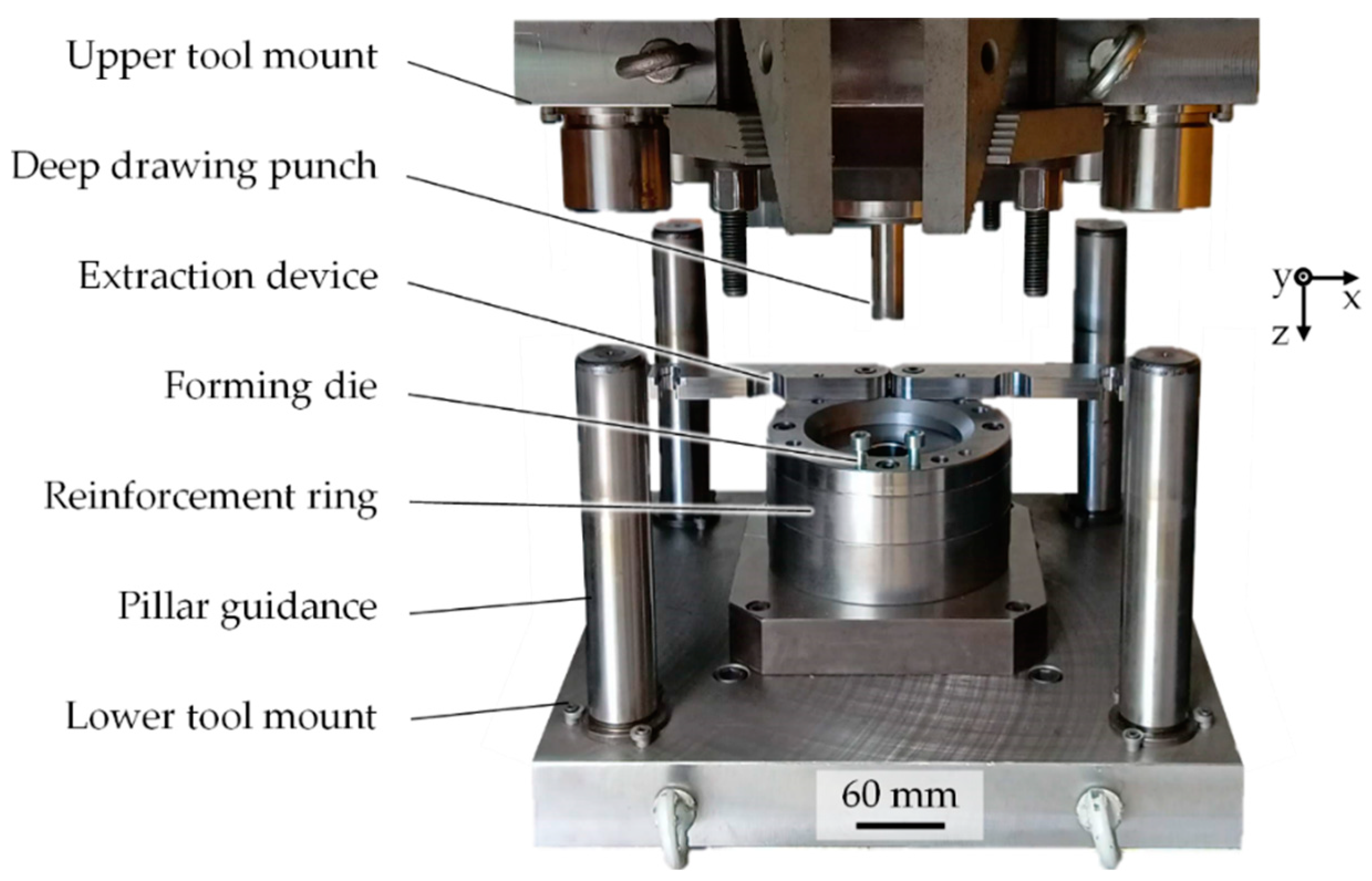
In the studies presented in this paper, the chromium-manganese alloyed case-hardening steel 1.7131 in the initial sheet thickness of 2.4 mm was used as a reference material. The steel was characterized by a low carbon alloy content of a maximum of 0.19% and a dual-phase structure of martensite and ferrite. The production of the tappet with the required microscopic texture geometry was realized using the tool setup shown in
Figure 1. This enables the three required process steps, deep drawing, ironing, and cam tappet, to be combined in a single press stroke. The punch was positioned in the upper tool holder and transferred the pressing force to the workpiece. A hole in the extractor allows the punch to be inserted into it. To ensure high positioning accuracy, the die plates were connected with column guides. The forces from the reinforced die were transferred to the press table via the lower tool holder.
The cam tappet was implemented using a structured coining cylinder, which was provided with the negative geometry of the subsequent indentations on the component surface. The structuring of the tool for the forming tests was carried out on an erosion machine (SX-200-HBM EDM system, Sarix SA, Sant’Antonino, Switzerland). This works according to the principle of spark erosion, in which a pulsed electrical high-frequency discharge is introduced into the workpiece by a tungsten electrode [
49]. Small amounts of material particles are thereby released from the workpiece. During the discharge, a dielectric fluid flows around the engaged electrode. Its tasks are the control of the discharge pulsation, the absorption of heat, and the removal of dissolved particles [
50].
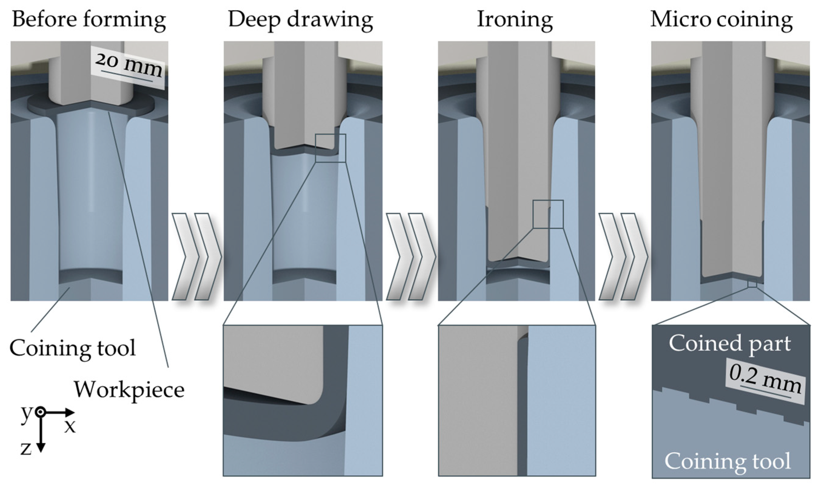
Due to the rear turning of the deep drawing punch, the manufactured component did not adhere to the die during the subsequent return stroke. The textured cup was released from the punch at the extraction device. The corresponding process kinematics for the single-stage forming is shown in
Figure 2.
The single-stage process of kinematics comprises three steps: deep-drawing, ironing and micro-coining. Initially, the float-mounted punch contacts the oiled steel blank. Due to the drawing ratio of 1.5, no blank holder is required, which reduces tool complexity and enables the use of a single-acting press. As the process continues, the conical die leads to a uniformly reduced wall thickness and the desired cup height of the workpiece. Finally, the workpiece is compressed between the punch and the coining cylinder, whereby microstructures are embossed into the base surface. The ram retraction releases the component, which is then removed from the punch by the removal device, preventing renewed contact with the tool textures.
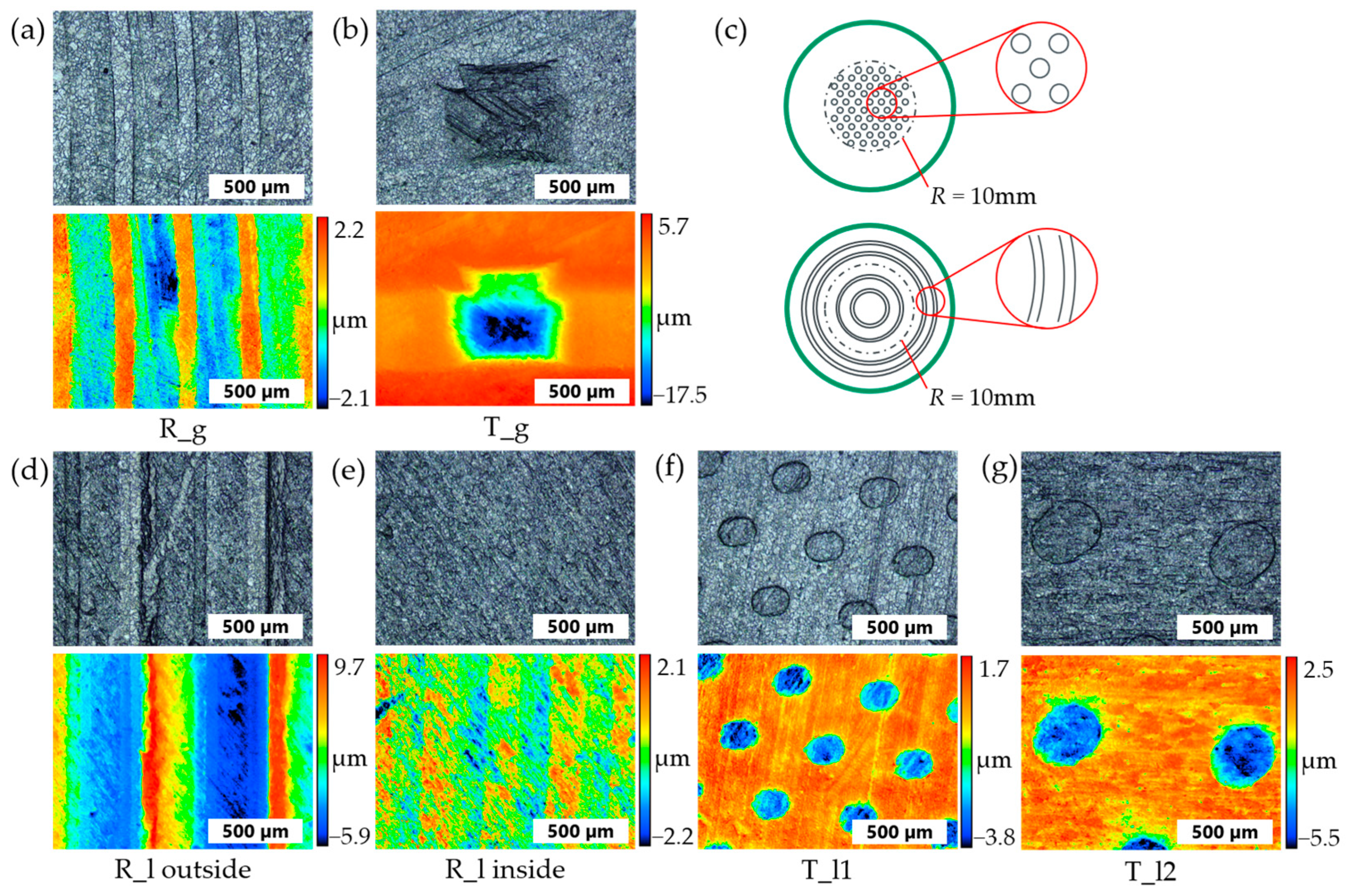
Texture patterns were selected for production that are interesting from a production engineering point of view on the one hand and, on the other hand, also fall within a range that can be considered rather favorable in terms of simulation (variants T_l1 and R_g). At the same time, unfavorable variants (T_g, T_l2 and R_l) were deliberately selected. The texture patterns labeled R were executed as concentric line textures arranged to the center of the tappet, while the textures labeled T represent discrete textures. On the one hand, global texture patterns were produced, which should be identical across the entire tappet (labeled g for global). In addition, different local textures were created (labeled l for local). The idea of local optimization is because optimal textures can be defined in the areas of the cam tip and cam flank contact.
2.4. Amorphous Carbon Coating
After the tappets were microtextured, the DLC-coating was applied without further post-treatment to test the feasibility of the coating on the microtextured surface and to identify the effect on the tribological behavior. Prior to deposition, the tappets were cleaned ultrasonically in acetone and isopropanol for 10 min each and afterward blown dry with nitrogen. An industrial-scale PVD deposition unit (TT 300 K4, H-O-T Härte- und Oberflächentechnik GmbH & Co. KG, Nuremberg, Germany) was utilized for coating fabrication. The DLC-coating was deposited under 2-fold substrate rotation on the tappets’ microtextured surface using a combined PVD/PECVD process. Prior to the coating process itself, the deposition chamber was evacuated to high vacuum conditions with an initial pressure of 5.0 × 10
−3 Pa and then heated to 250 °C for 40 min. Afterward, the tappet’s surface was (Ar+) ion plasma etched for 40 min with an argon gas flow (Ar purity 99.999%) of 500 sccm and a bipolar pulsed bias voltage of −500 V (pulse frequency 40 kHz, reverse recovery time 5 μs). The same cleaning process was carried out for the Cr and WC target (both a purity of 99.9%) with a dimension of 267.5 × 170 mm and closed shutters for 3 min to remove impurities from the target. The coating architecture consisted of a thin Cr adhesion layer, a graded CrWC intermediate layer and a WC support layer, which were deposited by PVD using unbalanced magnetron sputtering (UBM) in an Ar atmosphere. The relevant deposition parameters are listed in
Table 4. Subsequently, the functional layer of hydrogen-doped amorphous carbon (a-C:H) was deposited in a PECVD process utilizing a mixed acetylene-Ar (C
2H
2-Ar) plasma at 220 and 40 sccm, respectively, a bias voltage of −450 V, a chamber temperature of 100 °C and a substrate rotation speed of 3 rpm for 8580 s deposition time.
2.5. Characterization of Tools and Textured Tappets
The confocal microscope (VK-X 200, Keyence Deutschland GmbH, Neu-Isenburg, Germany) was used to characterize the microtextures on the component and tool sides. The measurement result was achieved by combining many focal planes with an incremental distance of 0.5–1.0 µm. To ensure a high resolution of the measured topography, the measurements were carried out at 500× magnification. In addition, height measurements of the texture surface were required to assess the accuracy of the micro-coining and to investigate the wear behavior. The analysis was carried out by defining the two measurement areas of texture and base. This procedure is necessary because the measurement method cannot give absolute height values, only relative values. The height of the texture results from the difference between the measurement area of the texture and the measurement area of the soil. With the aim of eliminating edge effects, the size of the texture measurement areas was defined as 70% of the nominal area of the top of the texture. A distance of 15 µm from the texture had to be considered for the placement of the measuring surface of the floor. An area corresponding to five times the target area of the top of the texture was used for the bottom area to achieve a sufficiently large measuring area for referencing the texture height. In addition, scanning electron microscopy (Merlin Gemini II, Carl Zeiss AG, Oberkochen, Germany) was used to assess the wear mechanisms of the tool-side textures and to evaluate selected textures on the tappets. To analyze the resulting texture patterns more closely regarding their geometry, representative laser microscopic images were taken (VK-X 3100, Keyence Deutschland GmbH, Neu-Isenburg, Germany) at 200× magnification.
2.6. Characterization of the Coating
To characterize the coating structure and coating hardness, round samples of tool steel (1.2379) were coated in the same process and then examined. The indentation hardness
HIT and indentation modulus
EIT were measured via nanoindentation (Picodentor HM500 and WinHCU, Helmut Fischer, Sindelfingen, Germany) in accordance with Oliver and Pharr [
51,
52]. Therefore, a Vickers indenter was utilized, and 17 indentations were produced with a force of 18 mN. The measurements were carried out using the standard application until the indenter attained the predetermined penetration force. In this case, the evaluation of the mechanical properties was performed at a penetration depth of <10% of the respective coating thickness to minimize the influence of the substrate [
53]. A FEI Helios Nanolab 600i (ThermoFisher Scientific, Waltham, MA, USA) with a focused ion beam workstation (FIB) was used to generate cross-sections to characterize the coatings. An accelerating voltage of 5 kV and a probe current of 0.69 nA were selected to image the microstructure. To demonstrate the layered architecture with the elemental composition of each layer, energy-dispersive X-ray spectroscopy (EDS) mappings were also performed. The same electron microscope with an Xmax
50 detector (Oxford Instruments, Abingdon, UK) was used for this purpose.
The surface roughness of the coating was measured directly on the non-textured tappets at 200× magnification using laser scanning microscopy (VK-X 3100, Keyence Deutschland GmbH, Germany) and compared with the roughness of the uncoated tappets. Four areas of 250 µm × 250 µm were measured on each of the three images, using an S-filter of 2 µm to match the measurement resolution. To examine the uniform coating thickness in the textures, the coated tappets were separated in the texture area, embedded, and then metallographically polished. As the epoxy resin used for embedding, the DLC-coating, and the substrate is abraded differently, images were taken and analyzed using focal stacking light microscopy (VK-X 3100, Keyence Deutschland GmbH, Germany) at 500× and 1000× magnification.
2.7. Tribological Characterization
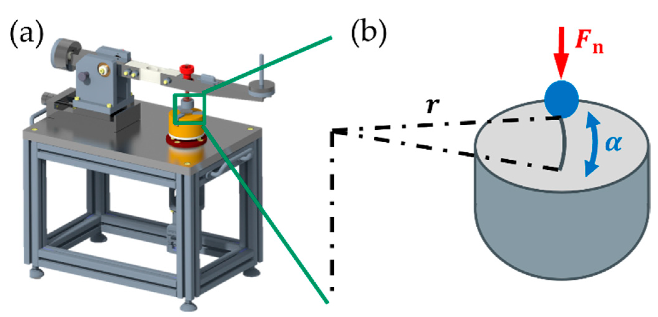
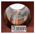
To fundamentally characterize the resulting friction and wear behavior, tribometer tests were carried out in a linear oscillating pin-on-disc configuration, as shown in
Figure 3. It should be mentioned at this point that, as a pure model test, these cannot be used for comparison with the simulations. 100Cr6 bearing balls with a diameter of
d = 4 mm were used as counterbody, and a test was carried out over 20,000 cycles for all textured cam tappets with the different variants.
In addition, two long-term tests with 200,000 cycles each were carried out on the DLC-coated tappets. The complete test conditions are summarized in
Table 5.
In addition to the average frictional force present in the contact, the wear of the counterbodies was also examined to determine the influence of the coating. The wear on the textured tappets, on the other hand, was only recorded qualitatively, as a quantitative evaluation of the wear volume is not possible or is associated with excessive external uncertainties. The evaluation of the counterbody wear was carried out using light microscopy (Metallux I, Leica, Wetzlar, Germany) at 200× magnification. The wear on the tappets was qualitatively analyzed using laser scanning microscopy (VK-X 3100, Keyence Deutschland GmbH, Germany) at 200× magnification. The differences in friction and wear behavior were evaluated using a two-sided t-test for unpaired samples.
3. Results
3.1. Simulation Process and Numerical Optimization
To investigate the extent to which the presented simulation approaches in 2D and 3D differ in their results, both simulations were carried out for the cam tip contact at 500 rpm (load case (a)) as an example.
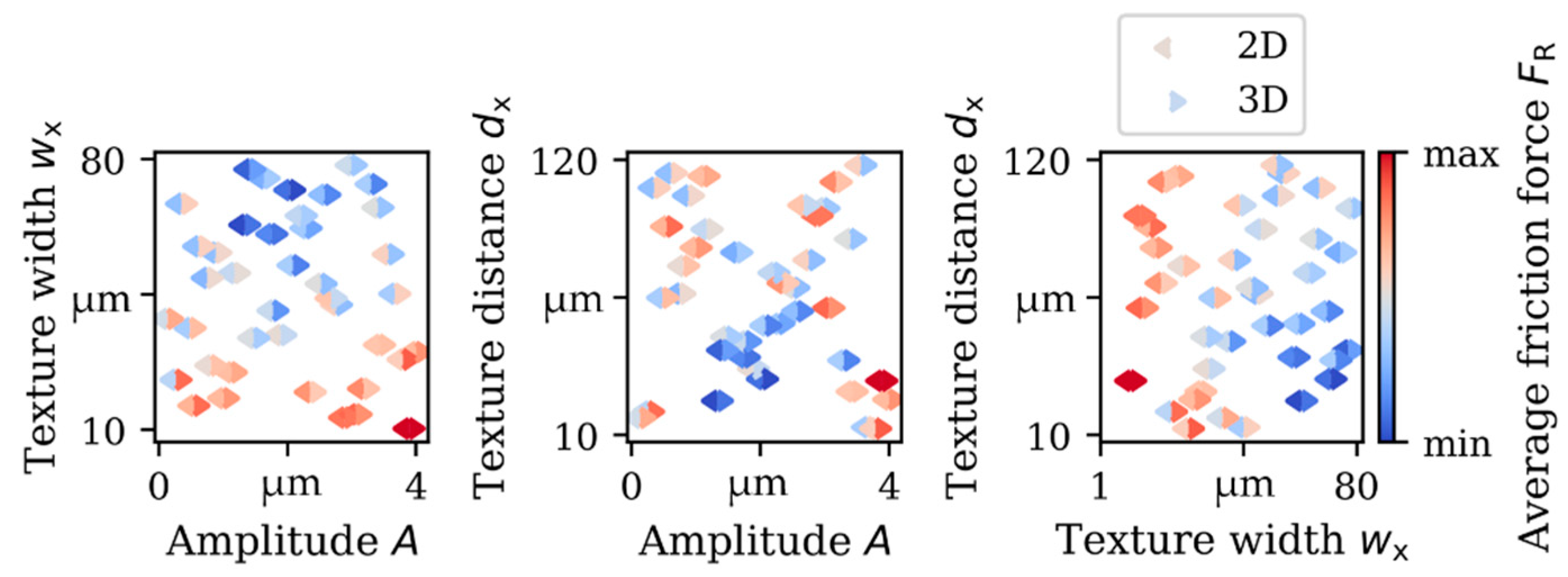
Figure 4 shows the mean friction force per test point for both models, with the force shown relative to each modeling approach. For improved visualization, the results are shown as a function of two of the three parameters.
It turned out that the simplified 2D simulation model led to similar results regarding the optimum textures. In particular, the globally clearly recognizable trend can be determined equally in both simulation approaches. For the load case (a) shown in
Figure 4, textures with a medium texture amplitude, a rather large texture width, and a medium to rather small texture distance can be qualitatively evaluated as advantageous.
The optimum textures determined using the GPR models for all load cases investigated are summarized in
Table 6.
The example of load case (a) shows that the numerically determined optimum falls within the optimum parameter range described above in purely qualitative terms, and the prediction quality is also very good in this case. It is also noticeable that the very different load cases lead to significantly different optimum textures. For example, while the optimum texture width at the cam tip contact decreases with the speed and the optimum texture distance increases, this is exactly the opposite for the flank contact. Apart from load case (b), the prediction quality of the developed GPR models can be rated as good. The model quality is particularly influenced by how well the test points describe the behavior in the parameter space. The prediction is particularly difficult in the case of ambiguous trends, as there may be several optimal parameter ranges for each load case instead of a specific optimum.
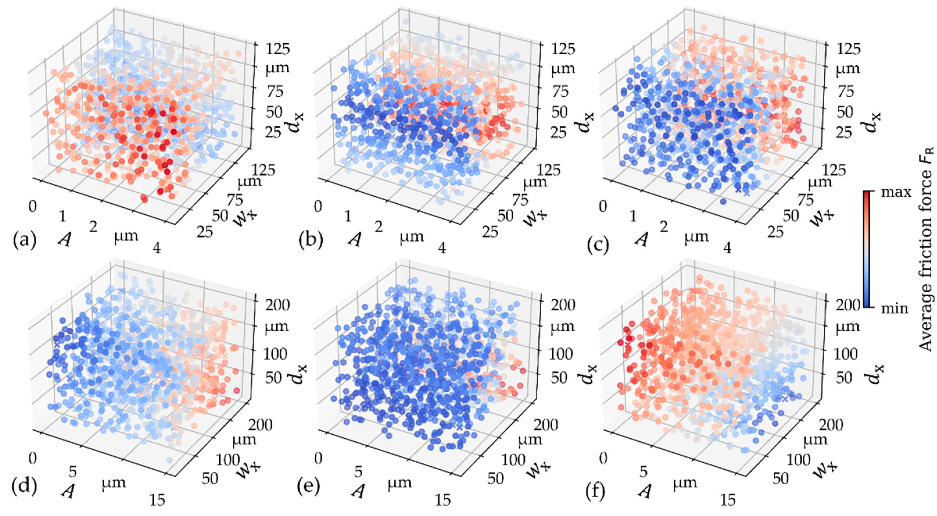
For this reason, the purely quantitative evaluation of the numerical optimum is not particularly meaningful without an additional consideration of the underlying model. However, the graphical evaluation of the results becomes more complex with just three parameters, as was the case in this work. To illustrate the trends in the parameter space, all six models developed are shown in
Figure 5. The predicted mean friction forces were evaluated and displayed for 1000 randomly generated parameter combinations.
The dependency on the parameters can be clearly recognized here. It is noticeable that for some load cases (e.g., (a) and (e)), there is a clearly recognizable optimization direction in the parameter range with a point optimum, whereas for others (e.g., (b) and (c)) there are larger, similarly optimum parameter ranges. Consequently, the prediction quality of these models is somewhat poorer.
3.2. Manufacturing Process Challenges and Solutions
Regarding the manufacturing process of the textured tappets, the challenges of the components, as well as the tools, are analyzed. The challenges were identified from internal forming tests carried out with the tool shown in
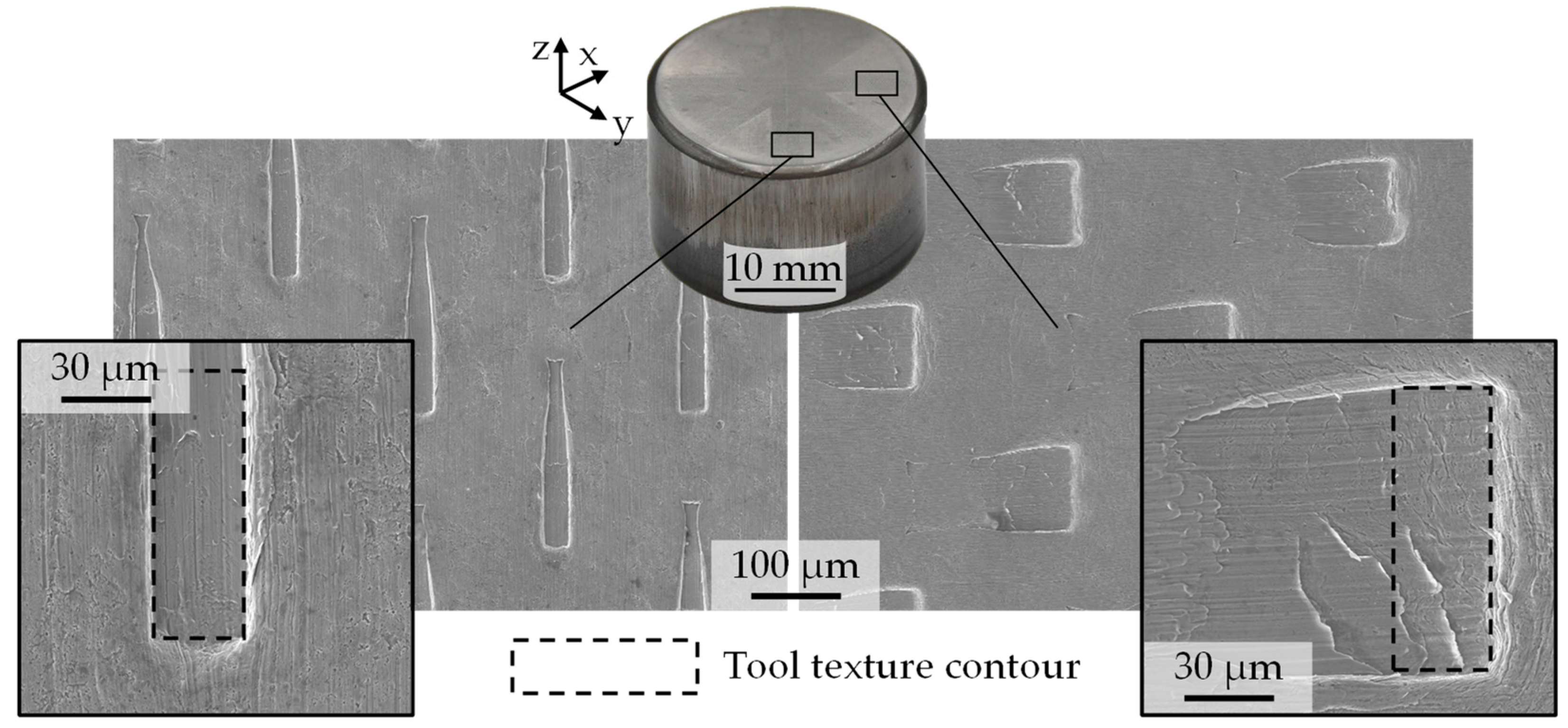
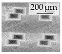
Figure 1. The distortion of the textures depending on the positions is a significant challenge of single-stage forming in combination with micro-coining. The textures created in the outer areas are shown in
Figure 6.
The explanation for this component error is the radial material flow that occurs in the last process step, during the compression of the component base between the punch and the coining cylinder. The material flow is lowest in the bottom center, which explains the good reproduction accuracy of the textures in this area. Only a slight superposition of the local material flow in micro-coining and the global material flow due to the compression process of the tappet base is, therefore, advantageous for achieving a low texture distortion. In contrast, higher radial displacements are found in the direction of the bottom edge. This suggests that the radial material flow overlaps the material flow from the micro-coining to a large extent and, therefore, has a negative effect on the dimensional accuracy of the textures on the workpiece side. In addition to the texture distortion caused by the radial material flow, further challenges were identified, which are summarized in
Table 7.
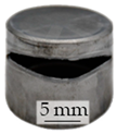
After only a few strokes, a local necking of the material forms on the outer wall of the base body near the radius. As the number of strokes increases, the necking spreads until it finally surrounds the cup wall. A further increase in the number of strokes results in material fracture, whereby the base below the radius is detached from the cup wall. This stage follows the states described in the literature [
54], consisting of crack initiation, crack propagation and crack arrest. As the boundary conditions are kept constant during component manufacture, a wear-related change in the tribological system can be assumed. An explanation for this is the increase in wall friction due to wear on the inner wall of the die. This increases the static friction that must be overcome when the finished component is removed from the die. If the static friction in the lower wall area exceeds the yield point of the material, necking can form at these points, which can lead to complete bottom tears if friction increases further. To counteract this, the die could be finished with a friction-reducing PVD or CVD coating, or the wall thickness of the cup could be increased.
In addition to macroscopic component failure, macroscopic component defects are identified. A major challenge in single-stage texturing is the creation of more than one texture pattern. Additional undesired texture patterns occur slightly offset from the original location. This is due to the inhomogeneous contact formation during the cam tappet. Partial loss of contact occurs between the semi-finished product and the embossing cylinder. The simultaneous radial material flow causes a relative displacement between the component and the tool. This leads to a second embossing pattern, which occurs at a different location compared to the first pattern. Possible remedies are provided by adapting the punch geometry, which prevents contact detachment and, therefore, relative displacement. In addition, an actively controlled counterholder can be used, which clamps the sheet before deep drawing and stretching and thus prevents the convex geometry of the component.
On the tool side, severe wear is detected on the inner radius of the die. Numerical analyses identify a particularly high contact pressure in this area. This is caused by the ironing and the resulting material build-up due to the reduction in wall thickness. For this reason, cold welding of the semi-finished material occurs on the die surface. As a countermeasure, a PVD coating containing titanium is applied to the inside of the die. This measure enables the complete elimination of this process error. A small draft angle, for example, offers the potential to reduce the contact pressures by distributing the forming zone over a larger area.
In addition to the wear of the die, the change in the texture surface on the tool side represents a significant process challenge. As the negative geometry of the tool is transferred to the component during micro-coining, texture wear on the tool side impairs the coining accuracy of the process. The causes and remedial measures are therefore described separately in the following section.
3.3. Application Behavior on the Tool Side
An abstracted coining process is used to investigate the wear behavior of the tool textures. This is introduced in [
55]. Since the deep drawing and ironing only have a minor influence on the work hardening in the cup bottom and thus on the tool load, the process for the wear investigation focuses on the cam tappet itself. The abstracted process, therefore, reproduces the indentation of the tool textures into the workpiece as well as the radial material flow with a sheet thickness reduction of 0.1 mm. The tool textures exhibit a height of 30 µm for the analysis. Although these are significantly higher than the structures identified as ideal in the simulation, wear mechanisms can already be identified at lower stroke rates. As fewer components must be produced, this measure contributes to more sustainable research.
The analysis is based solely on the texture height, as the main effects of wear on this dimension were shown in the previous investigations.
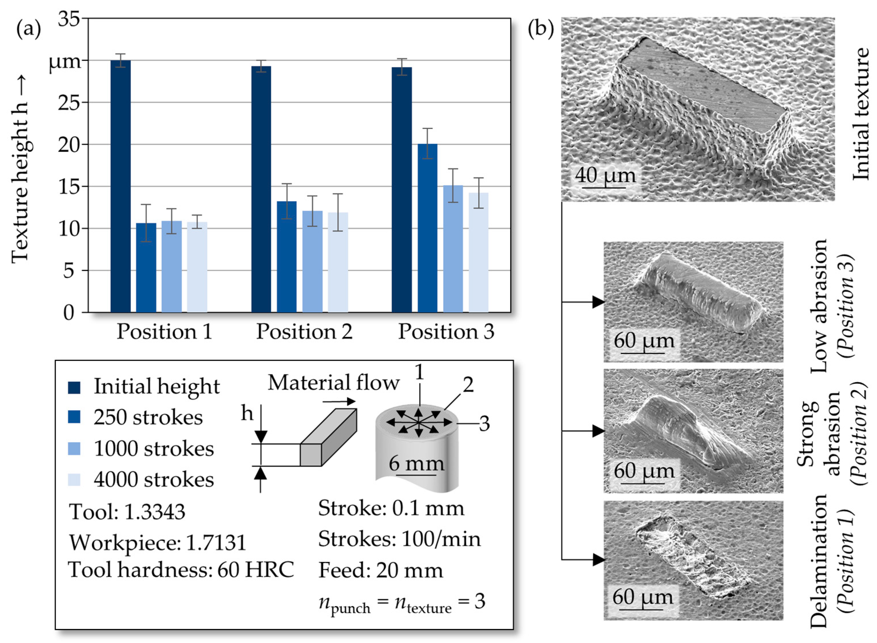
Figure 7a shows the development of the texture height at the three positions on the punch surface with three measured punches and three scanned textures per position.
For measuring Positions 1 and 2, a considerable decrease in texture height can already be seen after 250 strokes. Further strokes no longer lead to a continuous decrease in height. This is an indication that resistance to low-cycle fatigue is reached at the residual height of 10.8 ± 2.0 µm at Position 1 and 12.0 ± 1.6 µm at Position 2. The running-in phase at Position 1 is, therefore, already completed after 250 strokes. The degressive progression of the amount of wear is an indication of the state of the incubation period, in which no or very little wear is usually detected [
56]. However, a progressive increase in the amount of wear, which heralds the failure of the textures, cannot be detected even after 4000 strokes. The incubation period, therefore, continues, although its end is only to be expected after a large number of further strokes. The measurable amount of wear is almost constant during this time, as processes such as crack formation and growth, as well as microstructural changes, occur gradually and slowly.
In Position 3, a gradual wear behavior of the texture surface can be observed. This is the degressive increase in the amount of wear in the running-in phase. The decrease in texture height appears to run into saturation and thus into the incubation period in the range of 4000 strokes. Due to the supporting effect of the longitudinal side of the texture, textures that are arranged in the direction of the material flow are consequently less affected by wear.
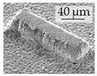
Initial textures before forming in
Figure 7b have a crater-shaped surface on the side faces. This is caused by the incremental discharge pulses in the micro-erosion manufacturing process. As the electrode is not in contact with the top surface of the textures, this surface remains in its original state. Only the characteristic fusion build-up forms at the edge between the side surface and the top surface. As shown in the previous section, the wear behavior is highly inhomogeneous and depends on the orientation of the texture. Therefore, to identify the wear mechanisms, SEM images of the orientations at 0°, 45° and 90° are examined. Textures at 0° are only affected by slightly abrasive wear. Particle removal is less pronounced in the bonding zone and increases towards the top surface. This behavior can be explained by the localization of stress peaks in tools at their edges and tight radii [
57]. Consequently, the abrasive wear at Position 3 is detected particularly on the side surfaces near the edge to the top surface. Due to the higher shear forces, highly abrasive wear occurs at Position 2 at an orientation of 45°. The material flow of the sheet metal strip causes particles to be detached from the surface of the base body by micro-chipping processes and repeated scoring [
56]. It is to be expected that these detached tool particles cause furrow wear on the outer tool surface due to the high hardness. They are transported further by the radial material flow. This also accelerates the abrasive wear of the textures located there.
In summary, it can be stated that the use of non-rotationally symmetrical texture geometries on forming tools for embossing processes leads to highly anisotropic wear behavior due to the relative orientations to the material flow. Depending on this alignment, the running-in phase or the incubation period still prevails after 4000 strokes. As the textures are wear-resistant at a height of at least 10 µm, the suitability of the process for the application under investigation has been proven. Generally, the texture depth of structured surfaces is mainly lower than 10 µm [
14]. The lower the required texture depth, the less critical the tool wear in combined forming processes. The manufacturing process presented is, therefore, suitable for most applications from a wear technology perspective.
3.4. Manufactured Textures
The resulting textures on the tappets are shown in
Figure 8. The production-related deviations from the ideal geometry described above can also be recognized here to some extent. The deviations from the ideal shape are particularly pronounced in the deeper patterns (see
Figure 8b,d). In contrast, the flat texture patterns R_g (
Figure 8a), T_l1 (
Figure 8f) and T_l2 (
Figure 8g) deviate only slightly.
3.5. DLC-Coating Characterization
The indentation hardness
HIT of the coatings was 25.8 GPa with an indentation modulus
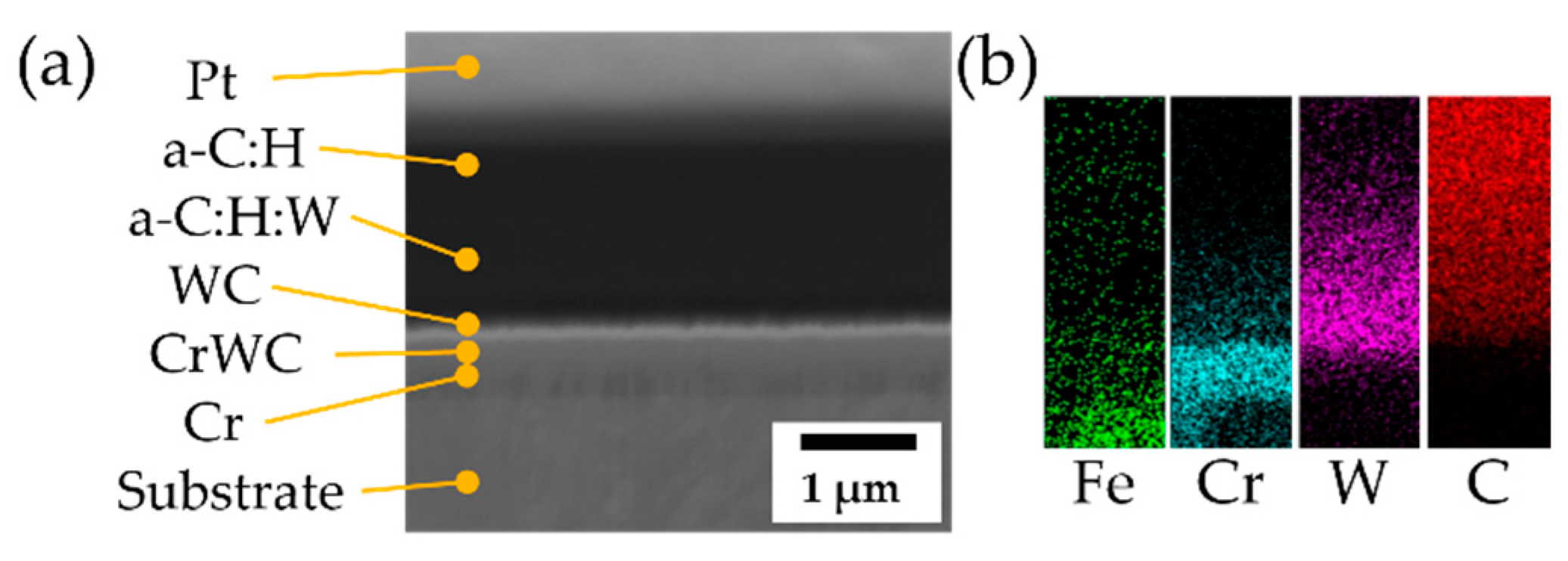
EIT of 199.9 GPa. The values are, therefore, within the usual range for DLC coatings. The design of the DLC coating is shown in
Figure 9a in the FIB cut. The adhesive layer consists of 0.3 µm Cr, 0.2 µm CrWC and 0.1 µm WC. The thickness of the a-C:H functional layer is approx. 2 µm, whereby the transition between a-C:H:W and a-C:H is not recognizable in the FIB cut. However, this can be seen in the corresponding EDS mapping in
Figure 9b.
Figure 10 shows three examples of microsections through the coated texture patterns T_g and T_l2. The exact position of the microsection cannot be determined. It is noticeable that the coating growth is not influenced by the textures, as they are very wide in relation to their depth. Shadowing effects, therefore, do not occur, and even in the areas of the texture edges (see
Figure 10g), a uniform coating application can be determined.
The measured roughness of the DLC-coated tappets is
(
) and
(
) and is therefore lower than the uncoated ones with
(
) and
(
). This can be explained by the fact that the surfaces are comparatively rough before coating, and the coating with a similar thickness clogs the fine structures of the surface due to the application process. The coarse shape of the surface, including the applied textures, on the other hand, does not change, which can also be seen in
Figure 10 as an example.
3.6. Tribological Behavior in Model Contact
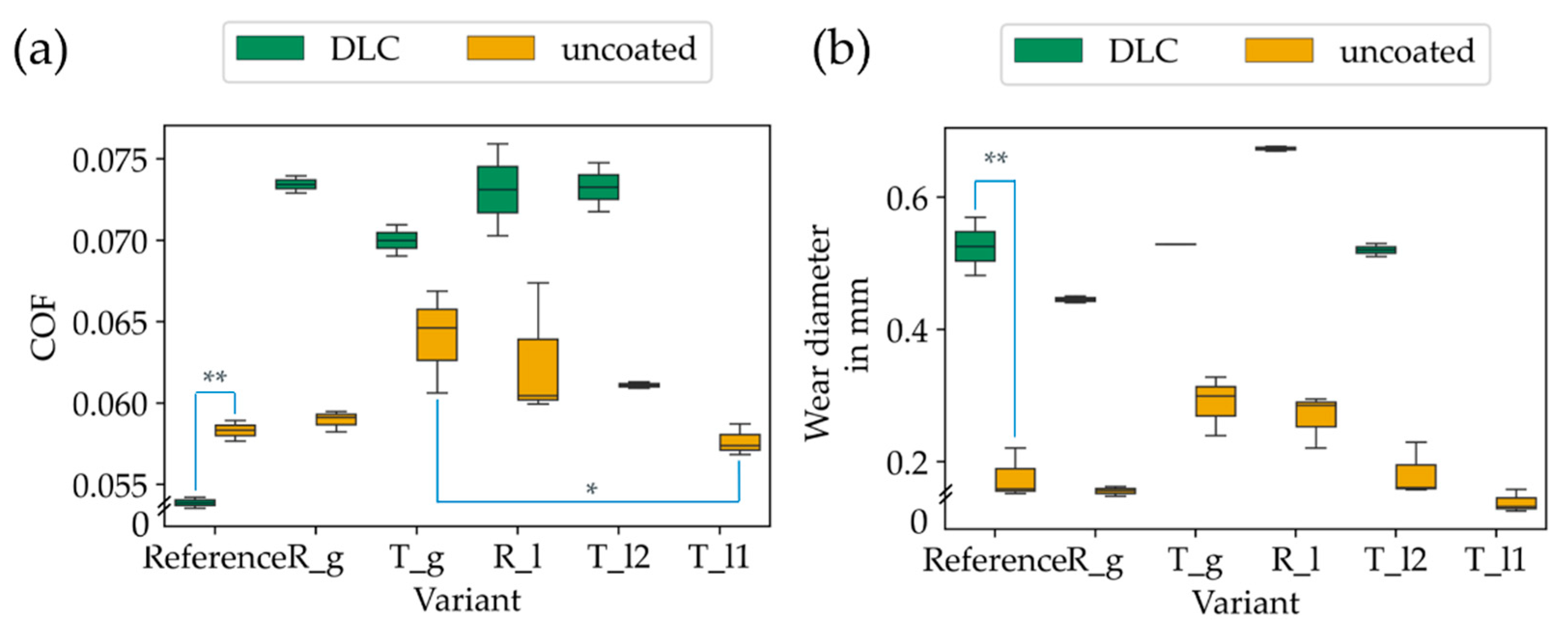
The results from the tribometer tests are shown in
Figure 11 as a function of the texture variant investigated and for the untextured reference.
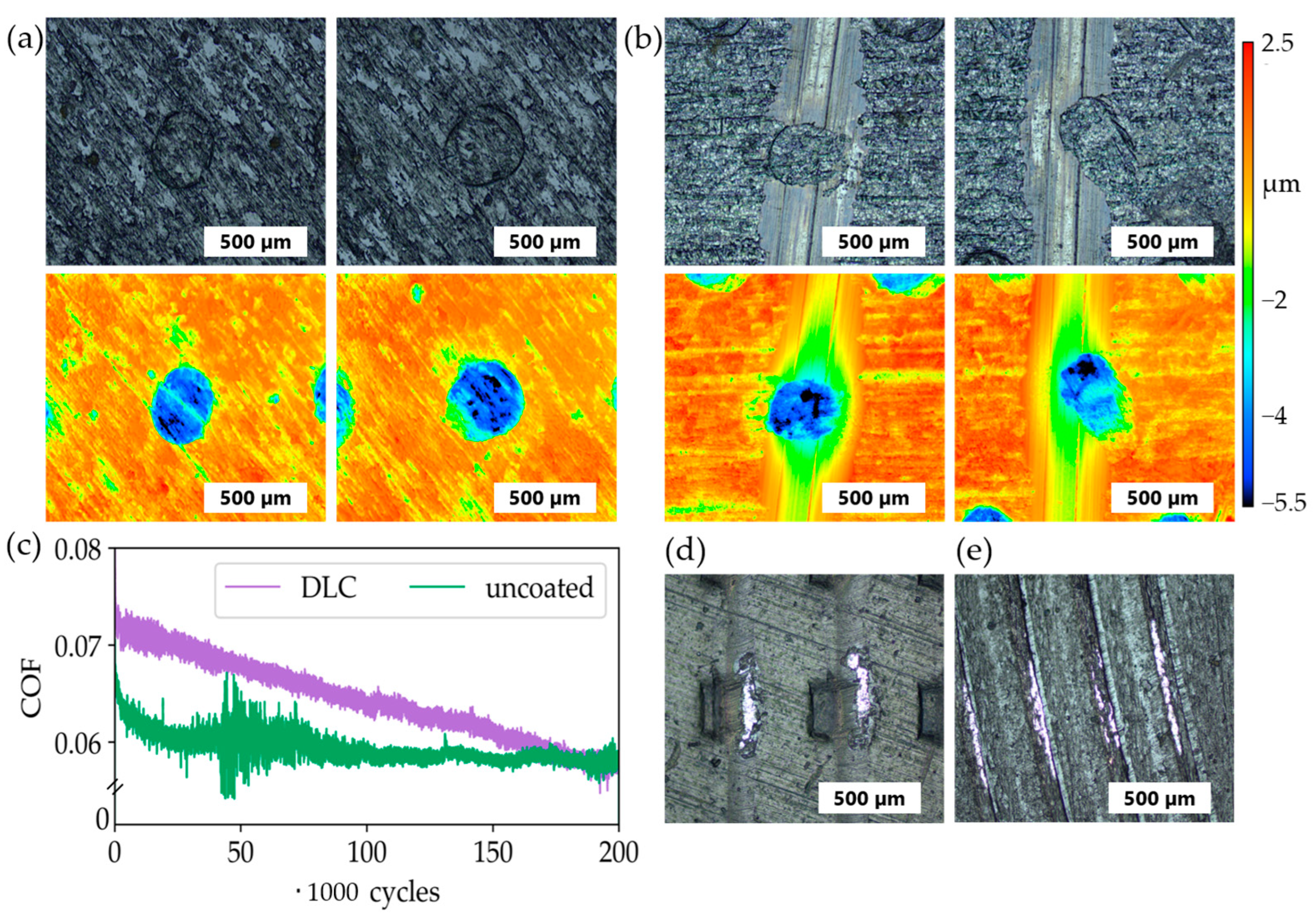
The amorphous carbon coating only led to a reduction in friction in the non-textured case, while the counter body wear increased considerably at the same time. In the case of uncoated samples, a clear difference was found between the optimized textures T_l1 and R_g compared to the textures T_g and R_l, which were assumed to be unsuitable, with negative effects presumably overriding the positive texture effect due to the shape deviations. However, only the difference in friction between T_g and T_l1 was significant, which may be due, among other things, to the sometimes-large variance in the repeated tests for tribometer tests. Additional long-term tests (see
Figure 12c) at the textures T_l2 show a clear running-in behavior of the coating until the friction level of the uncoated texture variant is reached after approx. 180,000 cycles.
This also explains why the COFs for the coated tappets were significantly higher in the short tests. At the same time, wear on the textures was completely prevented by the additional DLC-coating, whereas the uncoated tappets were already largely worn out after the long-term test (see
Figure 12a,b). In the case of the coated tappets, the light-colored areas in
Figure 12a indicate the running in of the coatings. Due to their unfavorable surface with protruding edges, however, the texture patterns T_g (see
Figure 12d) and R_l (see
Figure 12e) already showed coating failure at individual points in the short tests. With the textures T_l1 and R_l, however, no wear was recognizable there, as was also the case with T_l2.
4. Discussion
The numerical evaluation of textures using EHL simulation has long proven to be an effective approach, as it reduces the amount of experimental testing required. In the selected application example, the simplified model leads to similar results as the complete 3D contact model. By using the simplified model, the calculation time can be reduced considerably. For the investigated cam tappet contact, it could be shown that the optimal texture patterns strongly depend on the very different contact conditions, which makes it difficult to define a uniformly optimal texture since it would also have to be considered how long the respective conditions exist. For the load case (a), which is also considered to have similar boundary conditions and model structure, the results are similar to those from [
30]. From a numerical point of view, it can also be concluded that the textures in the center of the tappet should be smaller than in the edge areas, where a larger proportion of the cam flank is in contact. In addition to simply reading out the optimum parameters, the trend in the parameter space is also important for the evaluation of the optimization model to define sufficient textures.
The tendencies from the simulations could also be recognized in tribometer tests, but the positive effects are partly overlaid by the production-related deviations of the textures so that no effective friction reduction could be proven compared to the non-textured case. We must point out that the results of the theoretical simulation and texture optimization should not be compared directly with those of the pure model test.
For the coating of steel substrates, the substrates are often pretreated by polishing to low roughness values (Ra < 0.1 µm). This serves to ensure good adhesion of the coating to the steel substrate and that the roughness of the applied coating is not influenced by rough substrate surfaces. In tribological contacts, a high roughness of the coating often leads to high friction and, thus, abrasive wear of the counterbody if the coating exhibits a higher hardness than the contact partner, which in the case of the a-C:H coating against steel. Here, we investigated the possibility of coating application on the microtextured surface and found that it basically achieved excellent performance. The results of the tribological tests showed no flaking, delamination or severe wear of the a-C:H coating, meaning that coating adhesion under load remained stable. However, an exception applies to texture patterns with unfavorable and sharp edges. Here, the coating failure already occurred in the short tests on individual edges. Although the additional a-C:H layer applied to the texturing did not reduce friction in the short tests, the wear on the tappets was significantly reduced in long-term tests. The initially higher friction is presumably because the unfavorable edges on the textures caused by the production process are also protected against rapid smoothing and, therefore, have a negative effect on the contact. This means that the positive effect of an additional coating only takes full effect after the contact has been run in, and it can be assumed that friction is also reduced, as well as wear. Another option for future investigations would be to polish the coating after deposition.
The production of textured metallic components should be implemented using sustainable processes. Forming processes are particularly suitable due to their high resource efficiency. Texturing can thus be integrated directly into the production of the base body. The main challenges that have so far hindered implementation in an industrial environment are texture dimensional accuracy and tool wear. In this context, the measures identified in this study are designed to meet these challenges. Regarding the application of the cup tappet, where only low texture depths are required, it was also demonstrated that the process is also suitable for large quantities. Tool wear only plays a subordinate role at this texture depth.
