Abstract
This paper addresses the issue of the frequent collision and grinding of rolling elements in cageless bearings during operation by proposing a method to calculate the total circumferential clearance. The calculation is based on the maximum orbital speed difference in the bearing rolling elements to determine the minimum clearance needed to prevent collision. The study analyzes the impact of the rolling element diameter, bearing pitch diameter, contact angle, and number of rolling elements on the total circumferential clearance. The discussion then focuses on optimizing the number of rolling elements in cageless bearings. The optimization results demonstrate that the proposed calculation reduces collisions between rolling elements and bearing stress. Additionally, a total circumferential clearance test was conducted on a logarithmic spiral bearing, showing significant improvements in wear, average temperature, and temperature rise when designed according to the method presented in this article. These findings offer valuable insights into the design of cageless bearings.
1. Introduction
In bearing design, internal clearance is a crucial parameter, encompassing radial internal clearance, axial internal clearance, assembly clearance, and circumferential clearance. An overly small internal clearance increases friction and shortens bearing life, while a vast clearance reduces load capacity, increases vibration, and affects accuracy and stability [1]. Therefore, investigating the internal clearance of bearings is essential for optimal bearing design.
Stribeck [2] derived an equation for cage bearings to calculate the maximum load on rolling elements based on zero-radial-clearance ball bearings. Building on this, Mitrovic [3] introduced a load distribution coefficient and provided a detailed analysis of how internal radial clearance affects the static load rating of rolling bearings. Using the load distribution coefficient, Lazovic et al. [4] offered a comprehensive overview of load distribution in zero-clearance and positive-clearance ball bearings. Gao [5] proposed an analytical calculation model for high-speed ball bearings based on the Jones raceway control hypothesis, examining the effects of different clearances on bearing performance. Xiaoli et al. [6] explored a mathematical method for radial load distribution in ball and roller bearings under various clearances, proposing a pre-deformation model for non-zero-clearance bearings. Tomović [7] developed a mathematical model to determine the required boundary bearing deflection level in rolling bearings with internal radial clearance. Sinha et al. [8,9] created a mathematical model for radial load distribution with variable clearance. They examined the load deformation relationship in ball bearings with variable radial clearance under pure axial load, discovering that variable clearance can enhance the radial load capacity of ball bearings. Ambrożkiewicz et al. [10] analyzed the vibration response of self-aligning ball bearings under different radial clearances. Xu et al. [11] investigated the impact of bearing clearance on bearings’ vibration characteristics and skidding behavior. Ambrożkiewicz et al. [12] used a two-degree-of-freedom model to study the dynamic behavior of bearings with different clearances, treating radial internal clearance as a bifurcation parameter. Changqing and Qingyu [13] examined the dynamic characteristics of a rotor system supported by ball bearings, considering the combined effects of internal clearance and bearing surface waviness. Wang et al. [14] established a theoretical model for two-degree-of-freedom rolling bearings, analyzing the relationship between the number of inner ring equilibrium points and clearance. Kim [15] studied the effect of clearance between rollers and raceways on the cage slip rate. Liu et al. [16] investigated the impact of assembly clearance on the vibration characteristics of angular contact ball bearings. Chen and Qu [17] analyzed the impact of fit clearance failures during the assembly and the use of rolling bearings on system vibrations. Chen et al. [18] also studied the effect of bearing assembly clearance on the dynamic characteristics of bearings and proposed an optimized design method for assembly clearance based on dynamic analysis. Lioulios and Antoniadis [19] considered the impact of assembly compliance and internal clearance on the nonlinear behavior of bearing systems, examining how internal clearance affects system dynamic behavior. Yu et al. [20] established a reliability analysis model that includes internal clearance, studying its impact on bearing life prediction and reliability analysis. Yakout et al. [21] explored the effect of internal radial clearance on the damping characteristics, natural vibration modes, and fatigue life of rolling bearings. Oswald et al. [22] examined how internal clearance affects load distribution and fatigue life in deep groove ball bearings and cylindrical roller bearings, producing life factors versus internal clearance curves.
While there has been extensive research on the internal clearance of cage bearings, the internal clearance of cageless bearings has received less attention. Cageless bearings offer high load capacity, low cost, and excellent impact resistance, making them suitable for heavy-duty, low-speed, or high-impact load applications. However, without a cage to separate the rolling elements, these bearings frequently experience collisions and abrasion between rolling elements during operation, leading to surface damage, increased bearing temperature, and ultimately reduced bearing life. Total circumferential clearance is a crucial parameter influencing collisions between rolling elements. Therefore, studying the total circumferential clearance in cageless bearings is crucial for reducing collisions in their design.
This paper uses logarithmic spiral cageless bearings as a case study to investigate the calculation method for the minimum total circumferential clearance required to avoid collisions between rolling elements. It analyzes the influence of bearing parameters on this clearance, explores ways to reduce collisions by optimizing the number of rolling elements, and verifies the feasibility of this method through circumferential clearance experiments.
2. Cageless Logarithmic Spiral Bearings
2.1. Logarithmic Spirals
The logarithmic spiral, also known as the equiangular spiral, is illustrated in Figure 1. A logarithmic spiral is a curve where the angle between the tangent at any fixed point and the vector OP from a fixed point O to P (known as the strike angle) remains constant. Equation (1) presents the parametric equation of the logarithmic spiral. The logarithmic spiral finds extensive applications in mechanical engineering, aerospace, and other fields, offering new perspectives and inspiration for addressing various transmission challenges.
where a and k are constants, r represents the distance to the pole, and α denotes the strike angle.
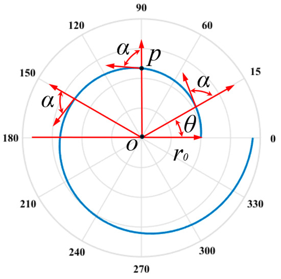
Figure 1.
Schematic diagram of logarithmic spirals.
2.2. Logarithmic Spiral Bearings
A logarithmic spiral bearing is a type of cageless bearing that consists of an outer ring, an inner ring, and rollers, as illustrated in Figure 2. A logarithmic spiral bearing features unique structural characteristics compared to traditional cageless bearings. The raceway profiles of both the inner and outer rings are logarithmic spirals. This design effectively prevents the rolling elements from erratically shifting in the axial direction, achieving axial self-locking of the rollers within the raceways, thus enhancing the stability and lifespan of the bearing.
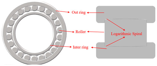
Figure 2.
Schematic diagram of logarithmic helix bearing structure.
2.3. Contact Angles of Bearings
Figure 3 shows a schematic diagram of the axial contact of the bearing. As depicted, under the action of only radial load Fr, the rolling elements have contact points a and b with the inner and outer rings of the bearing, respectively. Assuming the contact point a between the outer ring and the rolling element remains unchanged, the angle between the line connecting contact point b between the inner ring and the rolling element and the average passing through the center point O is the contact angle β. Since the magnitude of the contact angle β is independent of the bearing type but is related to the contact point b between the inner ring and the rolling element, this paper focuses on logarithmic spiral cylindrical roller bearings as the research object.
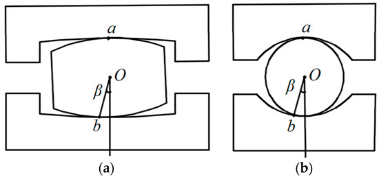
Figure 3.
Contact angle of logarithmic spiral bearing. (a) Cylindrical roller bearing. (b) Deep groove ball bearing.
3. Calculation and Influence Analysis of Total Circumferential Clearance of Cageless Bearing
3.1. Circumferential Clearance
As illustrated in Figure 4, the circumferential clearance of a cageless bearing refers to the gap between the rolling elements in the circumferential direction between the inner and outer rings. The total circumferential clearance is the sum of all gaps between the rolling elements in pairwise contact in the circumferential direction. For cageless bearings, both the circumferential and total circumferential clearance are vital for ensuring stability and reliability.
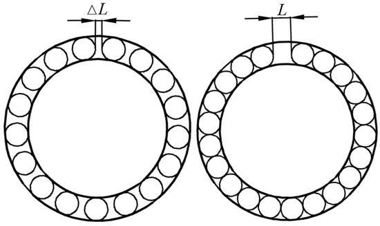
Figure 4.
Circumferential clearance of cageless bearings.
3.2. Calculation Method of Total Circumferential Clearance
In the kinematic analysis of the total circumferential clearance in cageless bearings, we assume the motion of the rolling elements is pure rolling without any slipping. We make the following assumptions for the analysis:
- (1)
- The bearing is in a stable state.
- (2)
- The rolling elements do not slip, tilt, or migrate.
- (3)
- There is no sliding at the contact points between the rolling elements and the raceways of the inner and outer rings.
3.2.1. Orbital Speed of Rolling Elements
Assuming that the inner ring of a cageless bearing rotates and the outer ring remains stationary, the rotational speed of the outer ring is zero, and the rotational speed of the inner ring is ni. The rotational speed of the roller is nr, and it rotates in a clockwise direction. The roller has a contact point with the inner and outer rings, as shown inFigure 5. The linear velocity at the point of contact between the roller and the inner ring is vi. The linear velocity at the point of contact between the roller and the outer ring is vo. The linear velocity at the center of the roller is vc. Based on the assumption that no sliding occurs at the contact between the roller and the raceway, the linear velocity at the points where the roller is in contact with the raceway is equal. Therefore, the linear velocity at the point of contact between the roller and the outer ring equals zero.
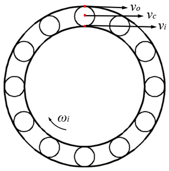
Figure 5.
The linear velocity of the contact point between the rolling element and bearing raceway.
During the operation of bearings, the linear velocity v can be expressed as follows:
where r represents the radius, and ω represents the angular velocity, which can be expressed as follows:
where n is the rotational speed.
According to the assumption, there is no sliding between the rolling elements and the raceways. Therefore, the circumferential linear velocity of the points where the rolling elements contact the inner raceway is equal to that of the points where the rolling elements contact the outer raceway. The linear velocity at the contact point between the rolling element and the outer race is vo = 0, while the linear velocity at the contact point between the rolling element and the inner race is vi.
It is assumed that the angle between the contact points of the rolling element with the highest and lowest points of the inner raceway is β, as shown in Figure 6. The linear velocity of the rolling element at the lowest point on the inner raceway is vi1, which can be expressed as follows:
where dm represents the pitch diameter, and Dw represents the diameter of the rolling element.
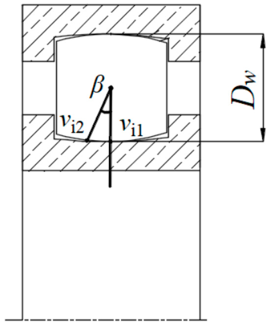
Figure 6.
Schematic diagram of bearing contact points.
The linear velocity of the rolling element at the highest point of the inner raceway is vi2 and can be expressed as follows:
The orbital speed of the rolling element is equal to the average linear velocity of its contact points on the inner and outer raceways:
where vi represents the linear velocity at the contact point with the inner race, and vo represents the linear velocity at the contact point with the outer race.
When the contact point of the rolling element is at the lowest point of the groove, the orbital speed of the rolling element is v1, which can be expressed as follows:
When the contact point of the rolling element is at the highest point other than the groove bottom, the orbital speed of the rolling element is v2 and can be represented as follows:
3.2.2. Calculation of Circumferential Clearance
As illustrated in Figure 7, assume that the inner and outer rings experience a relative displacement δr in the direction of the radial load Fr. Based on the deformation compatibility condition, the total displacement between the ith rolling element and the inner and outer rings are given by the following:
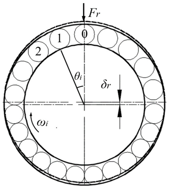
Figure 7.
Load distribution under the radial load of bearing.
In the equation, i denotes the index number of the rolling element, where the one experiencing the maximum load under radial load in the upward direction is indexed as 0, and the subsequent ones in the clockwise direction are indexed as 1, 2, 3……; θi represents the position angle of the ith rolling element.
According to Equation (11), when θi = 0, δi = δr = δmax, indicating that the contact deformation between the 0th rolling element and the raceway is at its maximum, and the load is at its maximum. When θi = 90°, δi = 0, indicating that the limit angle of the loaded region is ±90°, that is, the loaded region is 180°, with half of the raceway loaded. Due to the internal clearance in the bearing, the bearing area generated by the radial load Fr will be less than 180°. Therefore, at most, only half of the raceway rolling elements are loaded simultaneously.
As shown in Figure 7, half of the rolling elements in the bearing are assumed to bear loads, while the other half remain unloaded. Each loaded rolling element has one contact point with both the inner and outer raceways of the bearing. Assuming the center of mass of the rolling elements lies on the pitch circle, the circumference of the bearing pitch circle is denoted by S, which can be expressed as follows:
According to Equations (9) and (10), it can be observed that the rolling element has the slowest orbital speed at the lowest point of the groove and the fastest orbital speed at the highest point away from the groove bottom. Different orbital speeds are the fundamental cause of rolling element collisions and abrasion. Figure 8 illustrates a schematic of rolling element collisions. It is assumed that the rolling element A contacts the inner ring at the lowest point of the groove (the orbital speed of rolling element A is v1) and rolling element B contacts the inner ring at the highest point of the non-groove (the orbital speed of rolling element B is v2). When rolling element B rotates precisely half a turn and collides with rolling element A, the circumferential gap between rolling element A and rolling element B is represented by ∆L, as shown in Figure 8.
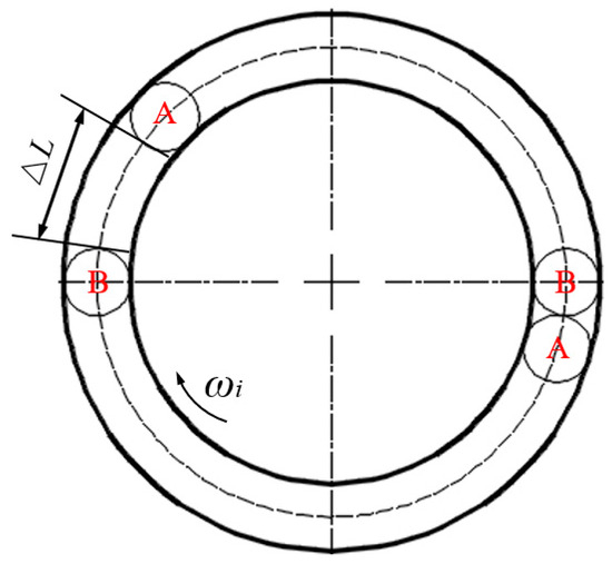
Figure 8.
Schematic diagram of rolling body collision.
From Figure 8, the distance traveled by rolling element A, denoted as SA, is equal to half of the circumference of the bearing raceway, denoted as S. SA can be expressed as follows:
The distance ∆L between rolling element A and rolling element B can be expressed as follows:
The spacing ∆L can be expressed as follows:
Substituting Equations (9), (10) and (13) into Equation (15), we obtain the following:
When the number of rolling elements in the cageless bearing is odd, the minimum circumferential clearance L to avoid rolling element collision can be expressed as follows:
When the number of rolling elements in the cageless bearing is even, the minimum circumferential clearance L to avoid rolling element collision can be expressed as follows:
3.3. Influence of Bearing Parameters on Total Circumferential Clearance
This study investigates the impact of rolling element diameter Dw, bearing pitch diameter dm, contact angle β, and the number of rolling elements Z on the total circumferential clearance L. Figure 9 presents the results, indicating that an increase in Dw, β, and Z leads to a higher L, while an increase in dm results in a lower L. Therefore, when designing the total circumferential clearance of a bearing, a larger Dw, β, and Z require an appropriate increase in L to prevent collisions and grinding between rolling elements. Conversely, a more prominent dm necessitates a reduction in L to prevent excessive stress on the bearing due to fewer rolling elements.
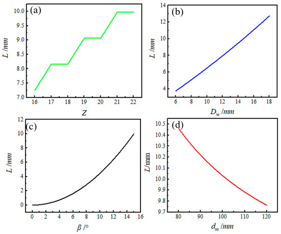
Figure 9.
Influence of design parameters on total circumferential clearance L. (a) Influence of rolling element diameter Dw on L. (b) Influence of bearing pitch circle diameter dm on L. (c) Influence of contact angle β on L. (d) Influence of number of rolling elements Z on L.
4. Optimization of the Number of Rolling Elements in Cageless Bearings
Using the traditional method for determining the number of rolling elements, the calculated total circumferential clearance L from Equations (17) and (18) exceeds the actual total circumferential clearance of the bearing, thus failing to reduce collisions and wear between the rolling elements effectively. To address this issue and effectively minimize collisions and wear, this paper proposes a new method to optimize the number of rolling elements. This optimization is conducted while keeping the rolling element diameter Dw, bearing pitch diameter dm, and contact angle β constant.
The traditional cageless bearing reduces internal stress by maximizing the number of rolling elements. The maximum number of rolling elements Zmax for the bearing can be expressed as follows:
where ⎣ ⎦ is the integer symbol.
The new method for calculating the number of rolling elements is as follows: the rolling element diameter Dw and the bearing pitch diameter dm are substituted into Equation (19) to obtain Zmax. Then, Zmax is substituted into Equation (17) or Equation (18) to obtain the minimum circumferential total clearance L to avoid rolling element collisions. Next, the sizes of the circumferential total clearance L and the actual circumferential total clearance Lactuality are compared. If the actual circumferential total clearance Lactuality value is more significant than L, the value of Zmax is output. Otherwise, Zmax = Zmax − 1, and then, it is substituted into Equation (17) or Equation (18) again until the value of Zmax is output. The specific calculation process is shown in Figure 10.
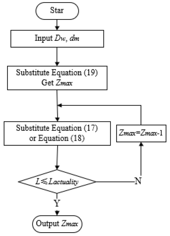
Figure 10.
Calculation flow of Zmax.
Xu [23] also proposed a method to reduce rolling element collisions and calculate the maximum number of rolling elements Zmax. A minimum angular clearance of 1° between two rolling elements of the bearing is required to ensure smooth operation. Therefore, the maximum number of rolling elements Zmax can be expressed as follows:
here ⎣ ⎦ is the integer symbol.
To compare three methods of calculating the number of rolling elements, this study uses the parameters of the bearing pitch circle diameter dm (103.7 mm), roller diameter Dw (14.63 mm), and contact angle β (15°) for calculations. The results of the calculations are presented in Table 1.

Table 1.
Calculation results of total circumferential clearance.
Based on the findings presented in Table 1, it is evident that the traditional method results in bearing clearance that is insufficient to prevent collisions, leading to increased wear between rolling elements. On the other hand, the method proposed by Xu et al. and the new method introduced in this study offers greater clearance than the minimum required to avoid collisions, effectively reducing wear and collisions. It is worth noting that Xu’s method has one less rolling element than the new method discussed in this paper, potentially leading to higher contact stress, increased risk of rolling element deflection, and ultimately impacting the bearing’s service life.
5. Circumferential Clearance Test of Bearings
5.1. Sample
The logarithmic spiral cylindrical roller bearing comprises an inner ring, an outer ring, and rollers. The machining of the logarithmic spiral raceways on the inner and outer rings involved six stages: forging, turning, heat treatment, rough grinding, finishing, and superfinishing. Utilizing a step-by-step approximation strategy, these processes formed the core of the manufacturing flow. The finished samples of the logarithmic spiral bearings are shown in Figure 11.
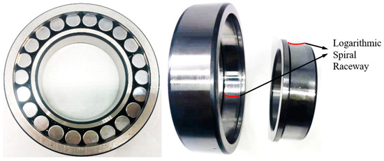
Figure 11.
Samples of the logarithmic spiral bearings.
We divided the experiment into the experimental group (EG) and the control group (CG), with each group testing bearings with different circumferential clearances. The circumferential clearance for the control group was 0.78 mm, less than the theoretical value of 9.967 mm. In contrast, the experimental group had a circumferential clearance of 15.2 mm, exceeding the theoretical value of 9.967 mm. Each group included four bearings, as shown in Figure 12. Each was fitted with a temperature sensor. We numbered the bearings 1 to 4 to correspond with temperature sensors 1 to 4. The bearing material, GCr15, is detailed along with specific dimensions in Table 2 and Table 3.
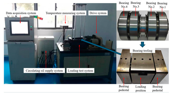
Figure 12.
The BLT-MST rolling bearing test machine.

Table 2.
Control group parameters.

Table 3.
Experimental group parameters.
5.2. Experimental Method
This study used the BLT-MST bearing testing machine to perform bearing clearance tests, as illustrated in Figure 12. Following the heavy load conditions specified for an aviation main shaft bearing, the tests followed the procedures listed in Table 4. During the tests, we closely monitored parameters such as shaft temperature, oil supply temperature, and spindle current for abnormalities. We continuously monitored and sampled the bearing temperature data until either we detected an abnormal change in the bearing parameters or the bearing operated stably for 250 h. At that point, we manually terminated the test.

Table 4.
Circumferential clearance test conditions.
6. Results and Discussion
6.1. Surface Abrasion Morphology
Due to excessive vibration, the bearing in the control group exceeded the warning threshold, causing the test machine to shut down after 196 h and 21 min of operation. In contrast, the bearing in the experimental group operated normally, and the technician manually stopped it after 262 h and 34 min. Post-test inspection revealed severe wear on the No. 1 bearing in the control group, with the rolling elements detached from the raceway. Bearings in No. 2, 3, and 4 also showed signs of wear. However, the experimental group’s bearings displayed no abnormal wear. Figure 13 illustrates the wear marks on the rolling elements after the test.
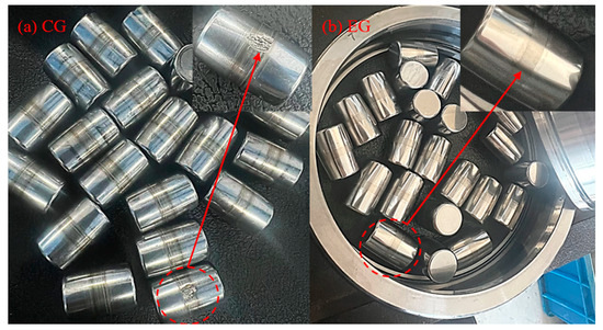
Figure 13.
Comparison of roller wear.
Figure 13 clearly illustrates that the wear marks on the control group’s rolling elements are more pronounced than those of the experimental group. Despite being subjected to identical speed and load conditions, the experimental group operated for an additional 3973 min relative to the control group. This result suggests that the problems of collision and wear between the rolling elements were more severe in the control group.
6.2. Temperature
Figure 14 illustrates the temperature test results of the control group bearings. The figure shows that after the bearing load reached 95 kN, the temperature initially increased slightly and gradually decreased. However, we observed significant fluctuations around 85 °C. Ultimately, we terminated the test prematurely due to vibrations exceeding the warning threshold.
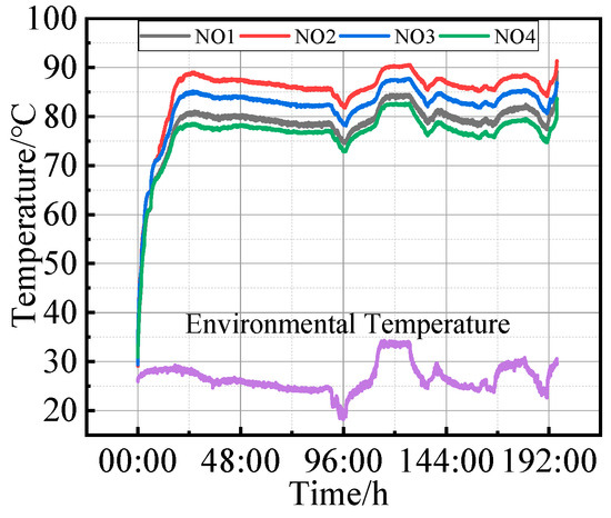
Figure 14.
Temperature test results of the control group.
When the load reached 95 kN, the increased friction and heat within the bearing caused a slight temperature rise. Over time, as the roughness of the contact surfaces between the rollers and the raceway decreased, friction reduced, and the temperature gradually declined. However, we observed significant fluctuations when the temperature approached 85 °C, potentially indicating abnormal bearing conditions. These fluctuations might have resulted from wear, collisions among the rolling elements, or other contributing factors, leading to operational instability and continuous temperature variation. Ultimately, when vibrations exceeded the warning threshold and we observed bearing wear, we could infer that the excessive vibration was due to the surface spalling of the rolling elements.
Figure 15 illustrates the temperature test results of the bearings in the experimental group. The graph indicates that the temperature steadily increased once the bearing load reached 95 kN. Subsequently, the temperature gradually decreased, followed by fluctuations around 78 °C. After some time, the temperature stabilized at 78 °C.
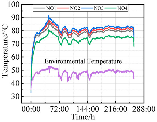
Figure 15.
Temperature test results of the experimental group.
As the bearing load reached 95 kN, the temperature rose due to increased friction and heat within the bearing. Over time, as the surface roughness decreased, the friction force and temperature gradually decreased. Despite stabilizing around 78 °C, fluctuations may still have occurred due to factors like internal bearing inhomogeneities, changes in lubricant viscosity, minor load variations, or shifts in environmental conditions. These interactions could have caused temperature fluctuations until the system reached a dynamic equilibrium. Once various factors reached a stable equilibrium, the temperature settled around 78 °C and remained relatively constant.
Figure 16 illustrates the data on the bearings’ average temperature and average temperature rise. The results show that the average temperature and average temperature increases for all bearings in the experimental group were lower than those in the control group. Specifically, the average temperature in the control group was 0.2–5.1 °C higher than that in the experimental group. However, the average temperature rise in the control group ranged between 21.8 and 26.7 °C. This difference could have been due to the impact of high ambient temperatures on the experimental group’s results. These temperature findings highlight the significant influence of the total circumferential clearance calculation method proposed in this study on reducing collisions and friction among rolling elements.
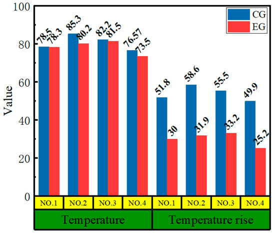
Figure 16.
Average temperature and average temperature rise results for bearings.
The total circumferential clearance calculation method proposed in this paper offers a more practical approach to designing an appropriate total circumferential clearance. This method can enhance the working performance of the bearing, minimize friction and wear, and prolong the bearing’s service life. The findings of this study hold significant implications for cageless bearing design and performance optimization.
7. Conclusions
This paper presents a novel method for calculating the total circumferential clearance of cageless bearings under radial force. The proposed approach minimizes collisions between rolling elements compared to existing calculation methods. The main contributions of this study can be summarized as follows:
- (1)
- As the diameter of the rolling elements, the contact angle, and the number of rolling elements increase, the minimum total circumferential clearance needed to prevent collisions also increases. Conversely, as the pitch diameter of the bearing increases, the minimum total circumferential clearance decreases.
- (2)
- To minimize collisions between rolling elements, the number of rolling elements in cage-less bearings was optimized. The optimization results indicated that with 21 rolling elements, the actual total circumferential clearance of the bearing ranges from 14.63 mm to 17.47 mm, exceeding the minimum required clearance of 9.967 mm to prevent collisions. Furthermore, this moderate total circumferential clearance helps reduce bearing stress, lower the risk of rolling element deflection, and extend the bearing’s service life.
- (3)
- Both experimental group (EG) and control group (CG) tests were conducted to validate the accuracy of the total circumferential clearance calculation. The results indicate that the control group experienced more pronounced wear marks and significant spalling than the experimental group. The average temperature and temperature rise in the control group were higher, with average temperatures exceeding those of the experimental group by 0.2 to 5.1 °C, and the average temperature rose by 21.8 to 26.7 °C. The comparison of wear marks, average temperature, and temperature rise demonstrates that the proposed calculation method effectively reduces collisions and wear between the rolling elements.
Author Contributions
Conceptualization, S.X.; writing—original draft preparation, X.Z; writing—review and editing, S.X.; methodology, T.X. and X.Z.; investigation, Q.X. and K.H. All authors have read and agreed to the published version of the manuscript.
Funding
This study was supported by the National Equipment Advance Research Grant Program Fund (Grant No. 6141C08).
Data Availability Statement
The original contributions presented in the study are included in the article; further inquiries can be directed to the corresponding author.
Acknowledgments
We are very grateful to Tranf Technology Co., Ltd. for its help in this study.
Conflicts of Interest
Author Shuidian Xu, Tao Xu, Qianqian Xu and Kai Huang were employed by the company Tranf Technology Co., Ltd. The remaining authors declare that the research was conducted in the absence of any commercial or financial relationships that could be construed as a potential conflict of interest.
References
- Dong, P.; Lai, J.; Guo, W. An analytical approach for calculating thin-walled planet bearing load distribution. Int. J. Mech. Sci. 2023, 242, 108019. [Google Scholar] [CrossRef]
- Stribeck, R. Ball bearings for various loads. Trans. ASME 1907, 29, 420–463. [Google Scholar]
- Mitrović, R. Analysis of the influence of internal radial clearance on the static load rating of the rolling bearing. Facta Univ.-Ser. Mech. Eng. 2001, 1, 1039–1047. [Google Scholar]
- Lazović, T.; Ristivojević, M.; Mitrović, R. Mathematical model of load distribution in rolling bearing. FMe Trans. 2008, 36, 189–196. [Google Scholar]
- Gao, S.; Wang, L.; Zhang, Y. Modeling and dynamic characteristic analysis of high speed angular contact ball bearing with variable clearance. Tribol. Int. 2023, 182, 108330. [Google Scholar] [CrossRef]
- Xiaoli, R.; Jia, Z.; Ge, R. Calculation of radial load distribution on ball and roller bearings with positive, negative and zero clearance. Int. J. Mech. Sci. 2017, 131–132, 1–7. [Google Scholar] [CrossRef]
- Tomović, R. Calculation of the boundary values of rolling bearing deflection in relation to the number of active rolling elements. Mech. Mach. Theory 2012, 47, 74–88. [Google Scholar] [CrossRef]
- Sinha, R.; Sahoo, V.; Paswan, M. Radial load distribution by balls in a ball bearing with variable clearance. Mech. Based Des. Struct. Mach. 2023, 51, 3538–3563. [Google Scholar] [CrossRef]
- Sinha, R.; Sahoo, V.; Paswan, M. An analytical method of axial load distribution of deep groove variable clearance radial ball bearings. Mech. Based Des. Struct. Mach. 2024, 52, 1669–1685. [Google Scholar] [CrossRef]
- Ambrożkiewicz, B.; Syta, A.; Gassner, A. The influence of the radial internal clearance on the dynamic response of self-aligning ball bearings. Mech. Syst. Signal Process. 2022, 171, 108954. [Google Scholar] [CrossRef]
- Xu, M.; Wang, M.; He, D. Skidding Behavior of Lubricated Rolling Element Bearings under the Influence of Oil Film and Radial Clearances. Tribol. Int. 2024, 194, 109500. [Google Scholar] [CrossRef]
- Ambrożkiewicz, B.; Syta, A.; Georgiadis, A. Experimental Verification of the Impact of Radial Internal Clearance on a Bearing’s Dynamics. Sensors 2022, 22, 6366. [Google Scholar] [CrossRef]
- Changqing, B.; Qingyu, X. Dynamic model of ball bearings with internal clearance and waviness. J. Sound Vib. 2006, 294, 23–48. [Google Scholar] [CrossRef]
- Wang, K.; Yang, H.; Wu, H. Theoretical model and experimental study of the influence of bearing inner clearance on bearing vibration. Eng. Fail. Anal. 2022, 137, 106247. [Google Scholar] [CrossRef]
- Kim, S. Analytical consideration of the radial clearance to reduce cage slip of the turbo engine roller bearing. J. Mech. Sci. Technol. 2021, 35, 2827–2839. [Google Scholar] [CrossRef]
- Liu, P.; Wang, L.; Ma, F. Influence of assembly clearance on vibration characteristics of angular contact ball bearings in the thermal environment. Tribol. Int. 2023, 181, 108317. [Google Scholar] [CrossRef]
- Chen, G.; Qu, M. Modeling and analysis of fit clearance between rolling bearing outer ring and housing. J. Sound Vib. 2019, 438, 419–440. [Google Scholar] [CrossRef]
- Chen, L.; Ma, F.; Qiu, M. Optimal design of clearances of cylindrical roller bearing components based on dynamic analysis. Math. Probl. Eng. 2022, 2022, 4811914. [Google Scholar] [CrossRef]
- Lioulios, A.; Antoniadis, I. Effect of rotational speed fluctuations on the dynamic behavior of rolling element bearings with radial clearances. Int. J. Mech. Sci. 2006, 48, 809–829. [Google Scholar] [CrossRef]
- Yu, A.; Huang, H.Z.; Li, H. Reliability analysis of rolling bearings considering internal clearance. J. Mech. Sci. Technol. 2020, 34, 3963–3971. [Google Scholar] [CrossRef]
- Yakout, M.; Nassef, M.; Backar, S. Effect of clearances in rolling element bearings on their dynamic performance, quality and operating life. J. Mech. Sci. Technol. 2019, 33, 2037–2042. [Google Scholar] [CrossRef]
- Oswald, F.; Zaretsky, E.; Poplawski, J. Effect of internal clearance on load distribution and life of radially loaded ball and roller bearings. Tribol. Trans. 2012, 55, 245–265. [Google Scholar] [CrossRef]
- Xu, H. Numerical Simulation and Optimization Design of Heavy Load Rolling Bearings. Master’s Thesis, Tsinghua University, Beijing, China, 2010. [Google Scholar]
Disclaimer/Publisher’s Note: The statements, opinions and data contained in all publications are solely those of the individual author(s) and contributor(s) and not of MDPI and/or the editor(s). MDPI and/or the editor(s) disclaim responsibility for any injury to people or property resulting from any ideas, methods, instructions or products referred to in the content. |
© 2024 by the authors. Licensee MDPI, Basel, Switzerland. This article is an open access article distributed under the terms and conditions of the Creative Commons Attribution (CC BY) license (https://creativecommons.org/licenses/by/4.0/).