Abstract
Incorporating graphene as ceramic additives can significantly enhance both the toughness and self-lubricating characteristics of ceramic matrices. However, due to the difficult dispersion and easy agglomeration of graphene, the preparation process of composite ceramics still faces many problems. In this study, a laminated laser-induced reduced graphene oxide/hexagonal boron nitride (L-rGO/h-BN) was introduced as an additive into a silicon nitride matrix, then a silicon nitride/reduced graphene oxide/hexagonal boron nitride (Si3N4/L-rGO/h-BN) ceramic composite was successfully synthesized using Spark Plasma Sintering technology. This approach led to enhancements in both the mechanical and self-lubricating properties of silicon nitride ceramics. This is due to the good monodispersity of the incorporating graphene in the silicon nitride matrix. The flexural strength and fracture toughness of the ceramic composite experienced notable increases of 30.4% and 34.4%, respectively. Tribological experiments demonstrate a significant enhancement in the self-lubricating performance of ceramic composites upon the incorporation of L-rGO/h-BN. The coefficient of friction and wear spot diameter experienced reductions of 26.6% and 21%, respectively. These improvements extend the potential industrial applications of Si3N4/L-rGO/h-BN ceramic composites. Throughout the friction process, the evenly exposed rGO and h-BN demonstrate an effective self-lubricating effect on the wear surface. This research paves the way for a novel approach to fabricating high-performance self-lubricating structural ceramics.
1. Introduction
Silicon nitride (Si3N4), recognized as a crucial engineering structural ceramic [1,2,3], has garnered widespread usage due to its exceptional properties, including high strength, elevated hardness, outstanding oxidation resistance, low coefficients of friction (COF), resistance to creep, thermal shock resistance, and corrosion resistance [4,5,6,7,8,9]. Currently, Si3N4 finds extensive application in automotive parts [10], mechanical lubrication bearings [11] and high-performance cutting lubrication tools [2,12,13,14,15]. As science and technology progress rapidly, the demand for Si3N4 structural ceramics in high-end technical equipment is escalating. This includes the need for more intricate structures [16,17] and lower COF [18]. The two-dimensional graphene network structure formed by the sp2 hybridization of single-layer carbon atoms exhibits remarkable attributes such as high strength, toughness, and excellent self-lubrication properties. Therefore, the Young’s modulus and intrinsic strength can reach 1000 GPa and 130 Gpa [19,20]. Graphene as an additive can greatly improve the mechanical properties of composite materials [21,22]. The incorporation of graphene as a ceramic additive has been shown to significantly enhance the toughness and self-lubrication properties of ceramics [23,24,25].
However, challenges, like graphene’s non-hydrophilic and non-oil-philic nature, low density, and tendency to aggregate, greatly hinder its application in ceramics [26]. Currently, there are three promising methods aimed at improving the dispersion stability of particles in the liquid phase [27,28]. The first method involves employing the steric stability mechanism, which entails introducing large long-chain molecules onto the surface of particles to impede agglomeration. The second method relies on the electrostatic stabilization mechanism, where suitable dispersants are chosen to ensure that particles carry similar charges on their surfaces, thereby enhancing dispersion. The third approach, known as the cooperative stability mechanism, involves introducing appropriate dispersants into the liquid phase, enabling a synergistic effect between steric and electrostatic stabilization mechanisms to achieve stable particle dispersion. However, these methods necessitate the use of chemical reagents, entail complex procedures, offer moderate modification effects, and can contribute to environmental pollution. Hence, there is a pressing need for a simple, environmentally friendly method for graphene surface modification.
Graphene, as an additive for ceramic-based materials, can greatly improve the mechanical properties and self-lubrication properties of ceramic materials. However, the easy agglomeration and low density of graphene limit its application in ceramic materials. In our previous research work [29], we successfully synthesized reduced graphene oxide/hexagonal boron nitride (L-rGO/h-BN) composites using laser irradiation in liquid. The h-BN and rGO exhibited a uniform distribution in sheet and sphere structures. Laser irradiation induced a loosening effect on the rGO due to the high temperature and pressure, while also increasing its surface charge, thus facilitating dispersion within the matrix. In addition, the introduction of h-BN improves the density of L-rGO/h-BN composites, addressing the challenges of poor dispersion and easy agglomeration associated with the low density of graphene within the matrix.
Therefore, we propose L-rGO/h-BN composites as additives into Si3N4-based ceramics, and prepare silicon nitride/reduced graphene oxide/hexagonal boron nitride (Si3N4/L-rGO/h-BN) ceramic composites by Spark Plasma Sintering (SPS) technology. Using the structural advantages of L-rGO/h-BN composite material enables the achievement of excellent dispersion within Si3N4-based ceramics. As a result, this approach enhances both the mechanical and the self-lubricating properties of the ceramic materials.
2. Experimental Section
2.1. Preparation of Si3N4/L-rGO/h-BN Ceramic Composites
- (1)
- Design of raw materials and components
In this experiment, α-Si3N4 was used as the main component, while the additive consisted of L-rGO/h-BN composite prepared through laser irradiation in liquid. Additionally, Al2O3 and Y2O3 were used as the composite sintering additives, with anhydrous ethanol serving as the dispersion medium, and polyethylene glycol was used as the dispersant. The key parameters of the main raw material used are illustrated in Table S1.
During the experiment, Si3N4/L-rGO/h-BN ceramic composites were prepared by dual power supply spark plasma sintering system (SPS-625HF, Fuji Electric Co., Ltd., Tokyo, Japan). The matrix of Si3N4/L-rGO/h-BN ceramic composite is composed of α-Si3N4, Al2O3, and Y2O3, with a volume ratio of 90:3:7, respectively. The addition amounts of L-rGO/h-BN composites varied at 0.25 wt%, 0.5 wt%, 0.75 wt%, 1 wt%, and 1.25 wt% of the matrix mass of the above Si3N4/L-rGO/h-BN ceramic composites, respectively, and the addition amount of dispersant polyethylene glycol was 2% of the matrix mass.
- (2)
- Preparation process
The preparation process flow chart is shown in Figure 1. The specific process flow is as follows.
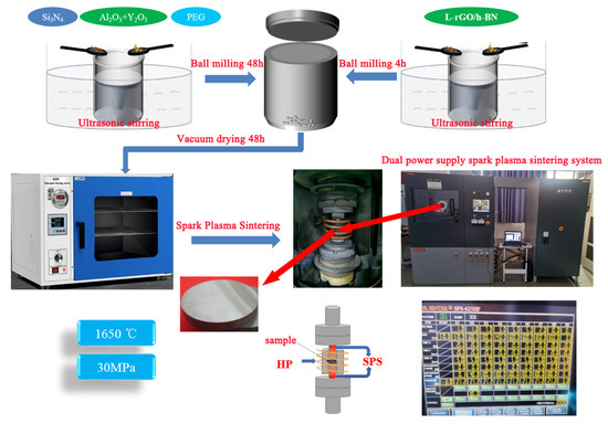
Figure 1.
Flowchart of the preparation process of Si3N4/L-rGO/h-BN ceramic composite.
(1) Weigh 12 g α-Si3N4, 0.5 g Al2O3, and 1.5g Y2O3 and add them to the beaker, and then add 100 mL anhydrous ethanol to the beaker to make mixed solution A. (2) Weigh 0.28g polyethylene glycol and add it to 30 mL anhydrous ethanol, stir it in a water bath at 60 °C for 10 min, wait for the polyethylene glycol to be completely dissolved, and add it to mixed solution A to make mixed solution B, and then stir mixed solution B ultrasonically for 4 h. (3) Mixed solution B was added to the ball mill tank, the aluminum oxide ball was used, the mass ratio of the ball was 10:1, and the ball was ground for 44 h under nitrogen protection atmosphere. (4) Weigh 35 mg L-rGO/h-BN composite material and add it to 20 mL anhydrous ethanol, ultrasonically stirring for 1 h to make solution C. (5) After 44 h ball milling of mixed solution B, solution C was added to mixed solution B, and the mixed slurry was obtained after continued ball milling for 4 h. (6) After ball milling, dry the mixed paste in a vacuum drying oven for 48 h at a temperature of 100 °C, and pass through a 200-mesh sieve after drying. (7) The mixture is dried and sieved and added to the mold. The mold diameter is about 30 mm and the sintering thickness is 5 mm. (8) The sintering temperature was 1650 °C, the sintering pressure was 30 MPa, the heating rate and holding time are shown in Table S2, and the sintering was cooled naturally after completion. (9) The as-prepared Si3N4/L-rGO/h-BN ceramic composite material was cut through the inner circle slice, coarse grinding, and fine grinding by the grinder, and then ground on the ground glass. The mechanical properties of the ground material were tested and the microstructure of the cross-section of the composite was observed. (10) The sintering process of different L-rGO/h-BN addition amount is different except for step (4); the other processes are the same.
2.2. Material Characterizations
X-ray diffractometer (XRD, D8-Advance, Bruker, Billerica, MA, USA) was used to analyze the crystal phase of raw powder material of the ceramic material before sintering and after sintering, in order to analyze the crystal pattern change before and after sintering. The morphology of the materials before and after sintering and the distribution of elements on the surface of the materials after sintering were analyzed by scanning electron microscope (SEM, FEI Quanta 250 FEG, FEI Company, Hillsboro, OR, USA). The bulk sample of 10 μm × 20 μm × 100 nm was prepared by using double focused ion beam electron microscope (FIB, Helios 5 CX, Thermo Fisher Scientific, Waltham, MA, USA). HAADF-STEM imaging and EDS analysis were performed by double spherical aberration correction transmission electron microscopy (HAADF-STEM, Spectra 300, Thermo Fisher Scientific).
2.3. Mechanical Property Test
The apparent density of ceramic composite materials was measured by the Archimedes water immersion method. The relative density of ceramic composite materials is then calculated. Vickers hardness was measured by the indentation method using a load of 196 N with holding time of 15 s on the polished surface. The fracture toughness was measured by the single notch beam method. The prefabricated width and depth of the middle area of the sample are about 0.2 mm and 1 mm, and the step speed of the indenting head load is 0.05 mm∙min−1. The three-point bending strength test method was used to test the bending strength of the material with a loading rate of 0.5 mm∙min−1 and sample span of 30 mm.
2.4. Evaluation of the Tribological Property
The tribological properties of Si3N4/L-rGO/h-BN ceramic composites were evaluated using high-speed reciprocating friction and wear test machine (MGW-02, Jinan Yihua Tribology Testing Technology Co., Ltd., Jinan, China). The method of ball-on-disc reciprocating motion friction is adopted. The experimental equipment and parameters are shown in Figure S1. A silicon nitride ceramic ball (diameter 6 mm, Shanghai Institute of Materials Co., Ltd., Shanghai, China) was selected as the ball, and Si3N4/L-rGO/h-BN ceramic composite material prepared in this experiment was selected as the disc. The experimental pressure is 10 N, the frequency is 5 HZ, the reciprocating distance is 7 mm, and the time is 20 min. During the experiment, the computer automatically recorded the COF data. In order to ensure the accuracy of the data, the friction experiment was repeated 3 times for each sample and the average value was taken as the COF value of the friction experiment. The COF data curve presented in this study is the average every 100 s.
After the experiment was completed, the surface of the friction pair was cleaned three times with petroleum ether, and then cleaned three times with anhydrous ethanol. The wear spot diameter (WSD) and morphology of the worn surface were observed by three-dimensional optical microscope (Contour Elite K, Bruker). The wear surface morphology and surface element distribution of different samples were observed by scanning electron microscope (SEM, FEI Quanta 250 FEG), and the self-lubricating mechanism was analyzed.
3. Results and Discussion
3.1. Phase Analysis of Si3N4/L-rGO/h-BN Ceramic Composites
α-Si3N4 possesses high hardness and wear resistance; however, due it is equiaxed structure, its fracture toughness is relatively low. In contrast, β-Si3N4 exhibits a long columnar crystal structure, offering comparatively higher fracture toughness, and certain self-lubricating properties [30]. Consequently, the sintering process in this study aimed to convert α-Si3N4 into β-Si3N4. Figure 2 illustrates the XRD pattern of the material before and after sintering. As we can clearly see, the XRD pattern of the raw material shows an obvious α-Si3N4 diffraction peak before sintering [31,32], along with sintering additives Al2O3 and Y2O3. The appearance of the h-BN diffraction peak indicates the successful addition of L-rGO/h-BN composites to the raw material. However, the XRD pattern does not reveal a GO diffraction peak, attributed to the poor crystallization of GO. Following sintering at a high temperature of 1650 °C, the XRD pattern shows the exclusive presence of β-Si3N4 crystals [33], while the diffraction peaks of Al2O3, Y2O3, and h-BN have disappeared, which is associated with low content of these substances and robust crystallinity of β-Si3N4. This outcome further confirms the successful transformation of α-Si3N4 into β-Si3N4.
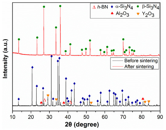
Figure 2.
XRD pattern of the material before and after sintering.
3.2. Mechanical Property Analysis of Si3N4/L-rGO/h-BN Ceramic Composites
As depicted in Figure 3a, the relative density of Si3N4/L-rGO/h-BN ceramic composite exhibits a trend of initially increasing and then deceasing with the rise in L-rGO/h-BN addition. When we further increase the concentration up to 0.75 wt%, the relative density reaches 98.9%, indicating maximal densification of the material after sintering at this concentration. Figure 3b shows the Vickers hardness value of Si3N4/L-rGO/h-BN ceramic composite at different addition concentrations. Notably, as the concentration of addition increases, there is a discernible decrease in Vickers hardness of Si3N4/L-rGO/h-BN ceramic composite. Even at 1.25 wt% addition concentration, the Vickers hardness of Si3N4/L-rGO/h-BN ceramic composite continues to decrease. The Vickers hardness value decreased by 14.4% from the initial 15.35 GPa to 13.14 GPa, which is the result of the addition of flexible L-rGO/h-BN, but the hardness can also meet the hardness requirements within the acceptable range of most friction pairs. Figure 3c,d show the flexural strength and fracture toughness values of Si3N4/L-rGO/h-BN ceramic composite at different addition concentrations. It can be seen from Figure 3c,d that both the flexural strength and fracture toughness increase first and then decrease with the increase in L-rGO/h-BN addition concentration. At 0.75 wt%, the bending strength and fracture toughness reached the maximum values of 887 MPa and 8.6 MPa∙m1/2, respectively, which increased by 30.4% and 34.4%, respectively. Indeed, these results can be attributed to the effective dispersion of L-rGO/h-BN in Si3N4-based ceramics, giving full play to its excellent mechanical properties.
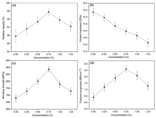
Figure 3.
Relative density and mechanical properties of Si3N4/L-rGO/h-BN ceramic composites at different L-rGO/h-BN addition concentrations: (a) relative density; (b) Vickers hardness; (c) bending strength; (d) fracture toughness.
3.3. Morphology and Elemental Analysis of Si3N4/L-rGO/h-BN Ceramic Composites
Figure S2 demonstrates the image of the α-Si3N4 raw material under SEM at different magnifications. As shown in Figure S2, the raw material presents an acicular crystal morphology, which is consistent with the crystal morphology of α-Si3N4 [34] and consistent with the results of XRD diffraction images. The cross-section SEM images of the Si3N4/L-rGO/h-BN ceramic composite at different L-rGO/h-BN addition concentrations are shown in Figure 4. As can be seen from Figure 4, after SPS sintering of the α-Si3N4raw material, the grain size changes from needle to columnar, indicating that β-Si3N4 has been successfully sintered [35,36]. When L-rGO/h-BN is not added, the ceramic composite after sintering contains certain pores, and the sintering effect is not good, as shown in Figure 4a. With the addition of L-rGO/h-BN (0.25 wt% and 0.5 wt%), the number of pores in the ceramic composite decreases, which is because L-rGO/h-BN is stably dispersed in the matrix. During the sintering process, the interaction between matrix grains is impeded, restraining abnormal grain growth and promoting grain refinement. However, cracks (Figure 4b) and particle size inequality (Figure 4c) still exist after sintering at this concentration. When the concentration reached 0.75 wt%, the ceramic composite exhibited the highest density after sintering, and the L-rGO/h-BN additive was closely combined with the ceramic matrix. During this period, the Si3N4/L-rGO/h-BN ceramic composite showed the highest bending strength and fracture toughness, manifesting in optimal mechanical property index, as shown in Figure 3 and Figure 4d. With the continuous addition of L-rGO/h-BN, due to the excessive concentration of the additive, agglomeration occurs to a certain extent and certain pores are formed, resulting in a weak area inside the ceramic composite, resulting in a decrease in mechanical properties [37,38], as shown in Figure 3 and Figure 4e,f. From the enlarged SEM image of the cross-section of Si3N4/L-rGO/h-BN ceramic composite (Figure 5a,b), it can be more clearly found that L-rGO/h-BN in the ceramic composite is tightly bound to the Si3N4 ceramic matrix when the concentration is 0.75 wt%, while the concentration is 1.25 wt%. The graphene in the ceramic composite was agglomerated to some extent, and L-rGO/h-BN was loosely bound to the Si3N4 ceramic matrix, resulting in porosity, which reduced the mechanical properties of the material.
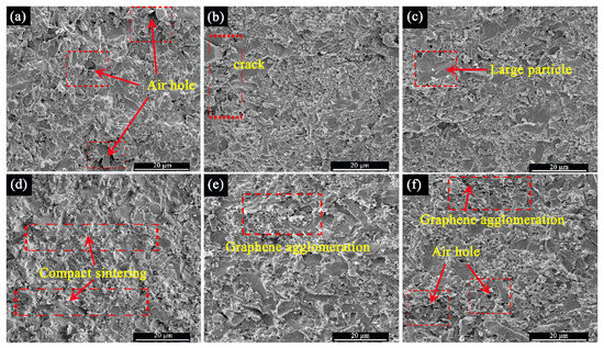
Figure 4.
SEM images of cross-sections of Si3N4/L-rGO/h-BN ceramic composites at different L-rGO/h-BN addition concentrations: (a) 0 wt%; (b) 0.25 wt%; (c) 0.5 wt%; (d) 0.75 wt%; (e) 1 wt%; (f) 1.25 wt%.
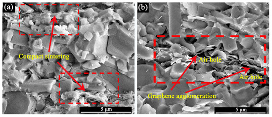
Figure 5.
SEM enlarged images of Si3N4/L-rGO/h-BN ceramic composites at different L-rGO/h-BN addition concentrations: (a) 0.75 wt%; (b) 1.25 wt%.
In order to analyze the distribution of elements inside the Si3N4/L-rGO/h-BN ceramic composite after sintering, the surface element distribution analysis was carried out on the cross-section of the ceramic composite with the optimal addition amount of 0.75 wt% L-rGO/h-BN, as shown in Figure 6. Figure 6a is the SEM image of the cross-section of the ceramic composite material. EDS element analysis was carried out at the L-rGO/h-BN additive position (point 1), as shown in Figure 6b. It can be seen that there are C, B, and N elements at point 1, which confirms the successful addition of L-rGO/h-BN. At the same time, it can be seen that it contains O, Si, Al, and Y elements, which is caused by the presence of Si3N4 and sintering additives Al2O3 and Y2O3 in ceramic composite materials. Scanning analysis of B and C elements on the cross-section of Figure 6a shows that B and C elements are evenly distributed in Si3N4/L-rGO/h-BN ceramic composite, as shown in Figure 6c,d, indicating that the added L-rGO/h-BN is evenly dispersed in the ceramic composite. Thus, the excellent mechanical properties of the ceramic composite can be ensured, and the mechanical properties of Si3N4/L-rGO/h-BN ceramic composite can be improved.
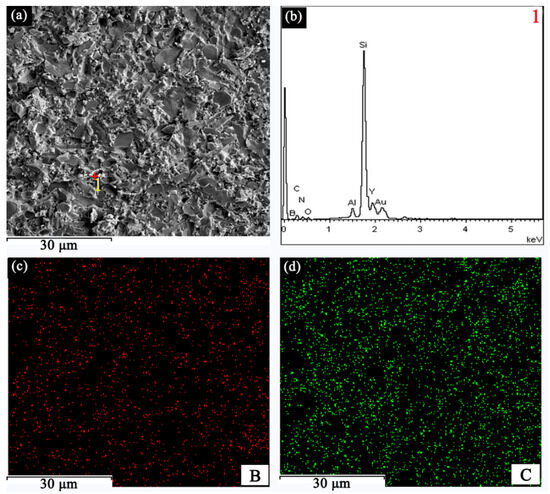
Figure 6.
SEM image of Si3N4/L-rGO/h-BN ceramic composite section and EDS analysis of elements at 0.75 wt% added concentration: (a) SEM images; (b) the EDS spectrum at point 1 in Figure (a); (c) B element mapping image of Figure (a); (d) C element mapping image of Figure (a).
In order to further analyze the bonding state of L-rGO/h-BN and Si3N4 ceramic matrix inside Si3N4/L-rGO/h-BN ceramic composite material, the sintered ceramic composite material was micro-processed using FIB, and finally thinned into a 10 μm × 20 μm × 100 nm flake sample, as shown in Figure S3. Then, the samples were subjected to HAADF-STEM imaging and EDS analysis by double-spherical aberration correction transmission electron microscopy, as shown in Figure 7. It can be seen from Figure 7a,b that after sintering, L-rGO/h-BN and Si3N4 ceramic matrix in Si3N4/L-rGO/h-BN ceramic composite is densely bonded, which leads to the improvement of the comprehensive mechanical properties of Si3N4/L-rGO/h-BN ceramic composite. The EDS mapping images of C, B, N, and Si elements (Figure 7c–f) show the distribution of elements more intuitively. The distribution of sintering additives Al2O3 and Y2O3 is shown in Figure 7g–i. It can be seen from Figure 7g–i that Al2O3 and Y2O3 are filled in the Si3N4 ceramic matrix and are closely combined with Si3N4, and the sintering effect is good.
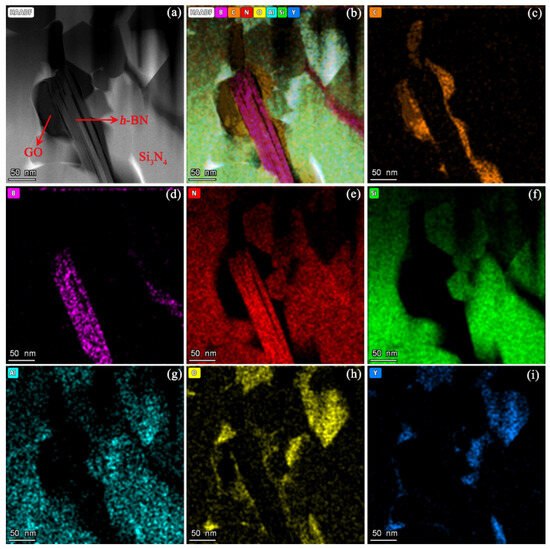
Figure 7.
STEM images of Si3N4/L-rGO/h-BN ceramic composites (0.75 wt% L-rGO/h-BN) and corresponding EDS mapping images: (a) STEM images; (b) EDS mapping images; (c) EDS mapping image of C element; (d) EDS mapping image of B element; (e) EDS mapping image of N element; (f) EDS mapping image of Si element; (g) EDS mapping image of Al element; (h) EDS mapping image of O element; (i) EDS mapping image of Y element.
3.4. Friction Performance Analysis
The self-lubrication performance of Si3N4/L-rGO/h-BN ceramic composite was analyzed by using the reciprocating friction test method of ball-on-disc, as shown in Figure 8. Figure 8a shows the change of COF curve of ball-on-disc friction test of Si3N4/L-rGO/h-BN ceramic composites prepared with different concentrations of L-rGO/h-BN (0 wt%, 0.25 wt%, 0.5 wt%, 0.75 wt%, 1 wt%, and 1.25 wt%) over time. As displayed in Figure 8a,b, when L-rGO/h-BN is not added, the average COF of the ball-on-disc friction experiment is the highest, at 0.537. The friction curve is unstable with large amplitude, and the standard deviation of the COF is 0.0086 (Figure S4a), while the COF tends to be stable after L-rGO/h-BN is added. With the addition of L-rGO/h-BN, COF showed a trend of decreasing first and then increasing. When the addition concentration was 0.75 wt%, the average COF dropped to 0.394, with the largest decrease, reaching 26.6% (Figure 8b), showing excellent self-lubrication effect. At this time, the COF curve is smoother, and the standard deviation is reduced to 0.0048. Compared with pure Si3N4, the standard deviation of the COF is reduced by 44.2% (Figure S4a). When the addition concentration was greater than 0.75 wt%, the COF began to increase, and when the addition concentration was 1.25 wt%, the average COF reached 0.512, but it was still smaller than the COF without L-rGO/h-BN friction experiment. This indicates that the self-lubricating effect of ceramic composite can be optimized only when the concentration of L-rGO/h-BN is optimal, and the optimal concentration of L-rGO/h-BN in this study is 0.75 wt%.
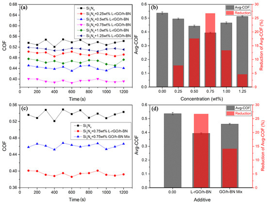
Figure 8.
Ball-on-disc friction experiments of Si3N4/L-rGO/h-BN ceramic composites prepared by adding different concentrations of L-rGO/h-BN: (a) changes of COF curve; (b) the corresponding average COF and the COF reduction compared with pure Si3N4 disc. Ball-on-disc friction experiments of Si3N4-based ceramic composites prepared by L-rGO/h-BN and GO/h-BN at 0.75% wt% concentration: (c) changes of COF curve; (d) the corresponding average COF and the COF reduction compared with pure Si3N4 disc.
To further demonstrate the improvement of self-lubrication performance of Si3N4/L-rGO/h-BN ceramic composite by L-rGO/h-BN sheet/ball structure after treatment by laser irradiation in liquid, we added the non-laser-treated GO/h-BN mechanical mixture into the Si3N4 ceramic matrix at an optimal concentration (0.75 wt%). After that, Si3N4/GO/h-BN ceramic composite was prepared by the same sintering process, and Si3N4/GO/h-BN ceramic composite was used as the friction pair to carry out the ball-on-disc friction experiment. The change curve of COF over time is shown in Figure 8c. As depicted in Figure 8c,d, after adding GO/h-BN mechanical mixture, COF also decreased from 0.537 to 0.461, a decrease of 14.2%, but the decrease was smaller than that of Si3N4/L-rGO/h-BN ceramic composite. At this time, the standard deviation of the COF is 0.005, which is greater than the standard deviation of Si3N4/L-rGO/h-BN ceramic composite (Figure S4b). This is due to the special sheet/ball composite structure of L-rGO/h-BN, which realizes uniform and stable graphene dispersion in the Si3N4 ceramic matrix, thus improving the self-lubricating effect of Si3N4/L-rGO/h-BN ceramic composite. The GO/h-BN mechanical mixture cannot be uniformly dispersed in Si3N4-based ceramics, which limits the self-lubricating effect of graphene on Si3N4-based ceramics.
Figure 9 is the average WSD and wear morphology of Si3N4 ball after the ball-on-disc friction experiment. As can be seen from Figure 9a,c, when L-rGO/h-BN is not added, the WSD of Si3N4 ball is 1172 μm after the ball-on-disc friction test. With the increase in L-rGO/h-BN addition concentration, the WSD of Si3N4 ball shows a trend of decreasing first and then increasing. The WSD decreased to 926 μm, with the largest decrease of 21% (Figure 9a,e), and the self-lubricating effect was the best at this time. When the addition concentration was greater than 0.75 wt%, the WSD began to increase, and when the addition concentration was 1.25 wt%, the WSD reached 1134 μm, which was still smaller than the WSD without L-rGO/h-BN friction experiment (Figure 9a). In order to compare the influence of L-rGO/h-BN sheet/ball composite structure on the self-lubrication effect of ceramic composite, Si3N4/GO/h-BN ceramic composite prepared by adding GO/h-BN mechanical mixture was used as a comparative experiment. The friction test results showed that after adding 0.75 wt% GO/h-BN mixture, the WSD is 1020 μm (Figure 9b,d), the reduction is 13%, and the self-lubrication effect is lower than that of L-rGO/h-BN. By comparing Figure 9c–e, it can be found that when L-rGO/h-BN composite material is not added, the WSD is not only the largest, but there is also the deepest wear furrow on the surface, indicating serious wear. After adding GO/h-BN mechanical mixture and L-rGO/h-BN, the WSD became smaller, and the surface wear marks began to become shallow. Among them, the appearance of the wear spots changed most significantly after adding L-rGO/h-BN. After adding L-rGO/h-BN friction experiment, Raman analysis was performed on the wear surface, and the results are shown in Figure S5. As can be seen from Figure S5, after the friction test, the same substance as L-rGO/h-BN additive was found on the surface of the Si3N4 ball, indicating that the additive repaired the surface of the Si3N4 ball, thereby reducing wear. This fully demonstrates the significant improvement effect of L-rGO/h-BN on the self-lubricating properties of Si3N4/L-rGO/h-BN ceramic composites.
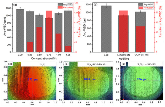
Figure 9.
Average WSD and the corresponding WSD reduction compared with the pure Si3N4 disc of Si3N4 ball after friction experiment: (a) Si3N4/L-rGO/h-BN ceramic composite prepared by adding different concentrations of L-rGO/h-BN; (b) ceramic composites prepared with L-rGO/h-BN and GO/h-BN at 0.75% wt% concentration. Wear morphology of Si3N4 ball after friction experiment: (c) L-rGO/h-BN was not added; (d) 0.75 wt% GO/h-BN mechanical mixture was added; (e) 0.75 wt% L-rGO/h-BN was added.
3.5. Self-Lubrication Mechanism Analysis
Figure 10 shows the SEM image of the wear marks on the surface of Si3N4-based ceramic discs after the ball-on-disc friction experiment and the distribution of C element on the surface of the wear marks. It can be clearly seen from Figure 10a–c that without adding L-rGO/h-BN, after the friction test, the surface of the ceramic disk was seriously worn, with the widest abrasion mark reaching 1150 μm, and serious spalling occurred in some areas, as shown in the area within the rectangular box in Figure 10c. After the GO/h-BN mechanical mixture was added, the surface wear degree was reduced, the width of the wear mark was reduced to 980 μm, no spalling occurred in the surface wear area, and the formation of similar lubricating film could be seen in some areas of the wear mark surface (Figure 10f). The self-lubrication performance of Si3N4/GO/h-BN ceramic composite was improved by the addition of GO/h-BN mechanical mixture, as shown in Figure 10d–f. Figure 10g–i show the SEM image of the wear surface of Si3N4/L-rGO/h-BN ceramic composite after L-rGO/h-BN is added. At this time, the wear width is 850 μm, and the wear width is reduced by 26.1% compared with pure Si3N4 ceramic, and the self-lubricating effect is significantly improved. More similar film formation can be found in the surface area of the abrasion (Figure 10i). In order to analyze the composition of the lubrication film on the wear surface, EDS element analysis was performed on the wear surface, as shown in Figure 10j,k. Figure 10j is the mapping image of C element in the SEM image region of Figure 10d. It can be seen from Figure 10j that C element is distributed in some areas of the surface of the wear marks, and a layer of graphene self-lubricating film is formed in some areas of the surface, which realizes a certain degree of self-lubricating of Si3N4/GO/h-BN ceramic composite material. Figure 10k is the mapping image of C element in the SEM image region of Figure 10g. Compared with Figure 10j, it can be clearly found that C element is evenly distributed in all areas of the worn surface, and a relatively comprehensive repair of the friction area is carried out. This is also why the addition of L-rGO/h-BN is more self-lubricating than the addition of GO/h-BN mechanical mixture.
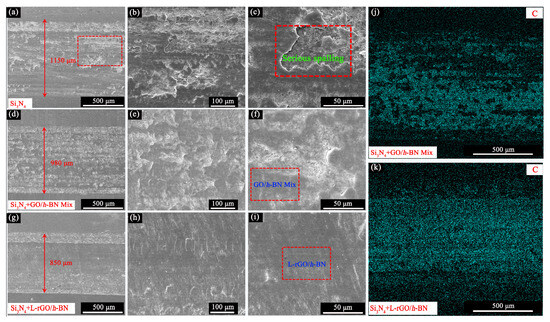
Figure 10.
SEM image of surface wear marks of Si3N4-based ceramic composites after friction test: (a–c) L-rGO/h-BN was not added; (d–f) 0.75 wt% GO/h-BN mechanical mixture was added; (g–i) 0.75 wt% L-rGO/h-BN pellet composite material was added. C element mapping image of surface wear of Si3N4-based ceramic composite: (j) 0.75 wt% GO/h-BN mechanical mixture was added; (k) 0.75 wt% L-rGO/h-BN composite material was added.
Figure 11 shows the formation mechanism of self-lubricating film of Si3N4/L-rGO/h-BN ceramic composite. Figure 11a is the schematic diagram of the reciprocating friction experiment of ball-on-disc. Before the friction experiment, the surface of Si3N4/L-rGO/h-BN ceramic composite material was intact and smooth, as shown in Figure 11a. L-rGO/h-BN is uniformly distributed in the matrix of Si3N4/L-rGO/h-BN ceramic composite. After the friction experiment began, the Si3N4 ball carried out reciprocating friction movement on the surface of the ceramic composite material, and the movement trajectory is shown in Figure 11c. With the progress of friction, the surface of the ceramic composite material is worn and peeled off, as shown in Figure 11b. At this time, the uniform distribution of L-rGO/h-BN is exposed, deposited on the surface, and accumulated on the surface of the abrasion to form a self-lubricating film. On the other hand, through the previous analysis, it has been confirmed that the internal Si3N4 ceramic matrix and L-rGO/h-BN are compact, coupled with the excellent mechanical properties of L-rGO/h-BN itself, so with the progress of friction, the additive L-rGO/h-BN will not be easily pulled out and broken. As a result, the self-lubricating film formed by L-rGO/h-BN additive on the surface of the wear marks becomes thicker and thicker, and eventually covers the surface of the wear marks, as shown in Figure 11d, thereby improving the self-lubrication performance of the Si3N4/L-rGO/h-BN ceramic composite.
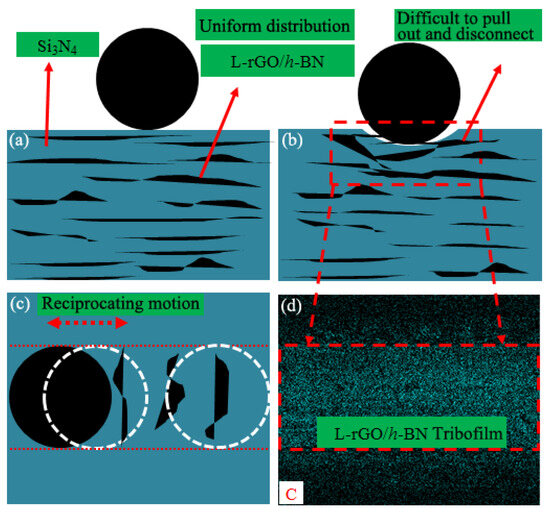
Figure 11.
Formation mechanism of Si3N4/L-rGO/h-BN ceramic composite self-lubricating film: (a) cross-section diagram of the ball-on-disc reciprocating friction experiment; (b) schematic diagram of cross-section wear in ball-on-disc reciprocating friction experiment; (c) top view of self-lubricating film formation mechanism after ball-on-disc reciprocating friction experiment; (d) the distribution of C element in the wear zone on the surface of Si3N4/L-rGO/h-BN ceramic composite after the ball-on-disc friction experiment.
4. Conclusions
In this study, the additive for Si3N4-based ceramics consisted of a composite structure of L-rGO/h-BN sheet/balls, which was prepared through laser irradiation in liquid. Subsequently, the Si3N4/L-rGO/h-BN ceramic composite was successfully prepared by SPS sintering process. This method improves the mechanical properties and self-lubricating properties of Si3N4-based ceramics, and improves the industrial application range of Si3N4-based ceramic composites. The main conclusions are as follows:
- (1)
- The optimum preparation parameters of Si3N4/L-rGO/h-BN ceramic composites are as follows. The volume ratio of α-Si3N4, Al2O3, and Y2O3 is 90:3:7, the sintering temperature is 1650 °C, the sintering pressure is 30 MPa, and the optimum concentration of L-rGO/h-BN additive is 0.75 wt%.
- (2)
- The Si3N4/L-rGO/h-BN ceramic composite was characterized by X-ray diffractometer, scanning electron microscope, and double spherical aberration correction transmission electron microscope. After sintering, α-Si3N4 is successfully converted to β-Si3N4. L-rGO/h-BN achieves good monodispersion in Si3N4 matrix due to its special sheet/ball composite structure. When the concentration of L-rGO/h-BN reaches 0.75 wt%, the Si3N4/L-rGO/h-BN ceramic composite is highly dense after sintering, and L-rGO/h-BN is closely bonded with the Si3N4 ceramic matrix.
- (3)
- After the addition of L-rGO/h-BN, the mechanical properties of Si3N4/L-rGO/h-BN ceramic composites are greatly improved. When the added concentration is 0.75 wt%, the relative density reaches 98.9%, and the bending strength and fracture toughness reach the maximum values, which are 887 MPa and 8.6 MPa∙m1/2, respectively, with increases of 30.4% and 34.4%.
- (4)
- The self-lubrication performance of Si3N4/L-rGO/h-BN ceramic composite was analyzed by ball-on-disc reciprocating friction experiment. The friction experiment shows that when the concentration of L-rGO/h-BN is 0.75 wt%, the COF decreases by 26.6% from 0.537 to 0.394, and the WSD decreases by 21% from 1172 μm to 926 μm. The standard deviation of COF decreases by 44.2% from 0.0086 to 0.0048, and the friction state is more stable. This is because of the special sheet/ball structure of L-rGO/h-BN additive and the successful sintering preparation of SPS. L-rGO/h-BN additive achieves effective dispersion in Si3N4/L-rGO/h-BN ceramic composite. During the friction process, graphene is exposed and deposited on the surface of the friction pair, which not only protects the surface of the friction pair, but also shows a good self-lubricating effect.
The tribological property research method in this study is mainly the linear friction method of point-surface friction at normal temperature, and the extreme temperature, surface–surface, and rotating friction methods are not studied. In the future, the research scope should be expanded, and the self-lubricating performance of ceramic composite materials should be further improved to continuously reduce energy consumption.
Supplementary Materials
The following supporting information can be downloaded at: https://www.mdpi.com/article/10.3390/lubricants12060219/s1, Table S1: The main raw materials and main parameters of Si3N4/L-rGO/h-BN ceramic composite. Table S2: List of heating rate and holding time in sintering process. Figure S1: Experimental equipment and parameters of ball-disc reciprocating friction: (a) experimental equipment and (b) Experimental parameters. Figure S2: SEM image of α-Si3N4 raw material: (a) low power and (b) High magnification. Figure S3: FIB thinning process of Si3N4/L-rGO/h-BN ceramic composite at 0.75 wt% added concentration: (a) Si3N4/L-rGO/h-BN cross-section STEM images and (b) flaky sample after FIB thinning. Figure S4: Standard deviation of COF: (a) Different addition concentrations and (b) Different additives at 0.75 wt%. Figure S5: Raman spectra of wear surface on Si3N4 ball: (a) Wear morphology of Si3N4 ball after friction experiment with 0.75 wt% L-rGO/h-BN and (b) Raman spectra of Points 1, 2 in Figure S5 (a) and L-rGO/h-BN.
Author Contributions
Conceptualization, W.L., S.I., T.L. and B.C.; Methodology, W.L., Y.D. and T.L.; Software, J.D., D.X. and J.L.; Validation, D.X.; Formal analysis, W.L. and Y.D.; Investigation, W.L., J.D., J.L. and B.C.; Resources, T.L. and B.C.; Writing—original draft, W.L.; Writing—review & editing, S.I. and T.L.; Supervision, B.C.; Funding acquisition, T.L. All authors have read and agreed to the published version of the manuscript.
Funding
This work was supported by Talent research fund (2023RCKY115), Basic research project of science, education, and production integration pilot project (2023PX090) of Qilu University of Technology (Shandong Academy of Sciences), Jinan Bureau of Education (JNSX2023015) and Jinan Bureau of Science and Technology (202333042).
Data Availability Statement
The original contributions presented in the study are included in the article, further inquiries can be directed to the corresponding author.
Conflicts of Interest
The authors declare no conflict of interest.
References
- Robert, B.H. Silicon Nitride Ceramics: Structure, Synthesis, Properties, and Biomedical Applications. Materials 2023, 16, 5142. [Google Scholar] [CrossRef] [PubMed]
- Andreas, Z.; Gerhard, M.; George, S.H.; Marcus, S.W.; Edwin, K.; Ralf, R.D.; Hartmut, F.; Peter, K.; Reinhard, B.H. Synthesis of cubic silicon nitride. Nature 1999, 400, 340–342. [Google Scholar]
- Naoya, S.B.; Stephen, J.P.; Tim, R.G.; Gayle, S.P.; William, A.S.; Paul, F.B. Observation of rare-earth segregation in silicon nitride ceramics at subnanometre dimensions. Nature 2004, 428, 730–733. [Google Scholar]
- Zhang, J.; Liu, G.H.; Cui, W.; Ge, Y.Y.; Du, S.M.; Gao, Y.X.; Zhang, Y.Y.; Li, F.; Chen, Z.L.; Du, S.X.; et al. Plastic deformation in silicon nitride ceramics via bond switching at coherent interfaces. Science 2022, 378, 371–376. [Google Scholar] [CrossRef] [PubMed]
- Tian, J.X.; Wu, Y.H.; Sun, J.; Xia, Z.X.; Ren, K.X.; Wang, H.; Li, S.H.; Yao, J.M. Thermal Dynamic Exploration of Full-Ceramic Ball Bearings under the Self-Lubrication Condition. Lubricants 2022, 10, 213. [Google Scholar] [CrossRef]
- Bai, Y.S.; Zhang, C.Y.; He, Z.; Cui, M.; Sun, D.C. Inverse solution to two-dimensional transient coupled radiation and conduction problems and the application in recovering radiative thermo-physical properties of Si3N4 ceramics. Int. J. Therm. Sci. 2023, 190, 108303. [Google Scholar] [CrossRef]
- Du, S.M.; Zhang, J.; Li, F.; Chen, Z.L.; Zhang, S.J.; Zhao, S.; Cui, W.; Chen, K.X.; Liu, G.H. Rapid fabrication of Si3N4 ceramics with gradient appearance and microstructure. J. Am. Ceram. Soc. 2023, 106, 7611–7617. [Google Scholar] [CrossRef]
- Chen, S.L.; Wang, C.A.; Wang, L.; He, G.; Li, J.T. Microstructure and properties of porous Si3N4 ceramics by gelcasting-self-propagating high-temperature synthesis (SHS). J. Adv. Ceram. 2022, 11, 172–183. [Google Scholar] [CrossRef]
- Frankberg, E.J. A ceramic that bends instead of shattering. Science 2022, 378, 359–360. [Google Scholar] [CrossRef]
- Moya, J.S.; Rodríguez, M.A.; Souto, A.; Guitián, F.; Pastor, J.Y.; Llorca, J.; Elices, M. Self-reinforced Si3N4 ceramics fabricated using Si3N4 produced by self-propagating high temperature synthesis. Scripta. Mater. 1996, 35, 991–997. [Google Scholar] [CrossRef]
- Sun, J.; Fang, X.; Yao, J.M.; Guan, R.Y.; Zhang, Z.; Zhang, G.X. Study on the Effect of Oil Supply on the Sound Field Characteristics of Full Ceramic Ball Bearings under Oil Lubrication. Lubricants 2023, 11, 146. [Google Scholar] [CrossRef]
- Liu, W.; Chu, Q.Q.; He, R.X.; Huang, M.P.; Wu, H.D.; Jiang, Q.G.; Chen, J.; Deng, X.; Wu, S.H. Preparation and properties of TiAlN coatings on silicon nitride ceramic cutting tools. Ceram. Int. 2018, 44, 2209–2215. [Google Scholar] [CrossRef]
- Wang, L.J.; Zhuang, Y.X.; Xing, P.F. Effects of Temperature and Si3N4 Diluent on Nitriding of Diamond Wire Silicon Cutting Waste. Silicon 2023, 15, 521–531. [Google Scholar] [CrossRef]
- Nallusamy, S. Investigations on silicon nitride superimposed nanocoated cutting tool by physical vapour deposition and atomic force microscopy. Appl. Nanosci. 2021, 11, 1107–1115. [Google Scholar] [CrossRef]
- Sun, H.W.; Zou, B.; Xue, K.; Chen, W.; Liu, J.K. Cutting Performance and Wear Behavior of Self-Developed Silicon Nitride Ceramic End Mills with Optimized Structure for High-Speed Machining of GH4099. Adv. Eng. Mater. 2023, 25, 2301008. [Google Scholar] [CrossRef]
- Zhang, H.Q.; Ye, F.; Liu, Q.; Zhang, B. The lamellar preparation of continuous porosity-graded Si3N4 ceramics without obvious interfaces for broadband radome application. J. Eur. Ceram. Soc. 2023, 43, 304–312. [Google Scholar] [CrossRef]
- Zha, H.K.; Yu, W.Q.; Li, J.W.; Shi, J.; Li, J.C.; Tang, W.M.; Lin, Y.H.; Zhu, K.S.; Cheng, J.G.; Liu, G.C. Progress in Preparation and Properties of Porous Silicon Nitride Ceramics. Silicon 2023, 15, 6631–6653. [Google Scholar] [CrossRef]
- Huang, H.; Wang, L.J.; Qi, Q.; Tang, H.G.; Li, T.Y.; Yang, Y.D.; Yu, Y.; Sun, H.Q.; Qiao, Z.H. Titanium nitride induced wide temperature range self-lubricating silicon nitride ceramics with low wear and stable low friction coefficient. Mater. Today. Commun. 2024, 39, 108729. [Google Scholar] [CrossRef]
- Jeroen, V.D.B. Graphene: From strength to strength. Nat. Nanotechnol. 2007, 11, 199–201. [Google Scholar]
- Balandin, A.A.; Ghosh, S.; Bao, W.Z.; Calizo, I.; Teweldebrhan, D.L.; Miao, F.; Lau, C.N. Superior thermal conductivity of single-layer graphene. Nano Lett. 2008, 8, 902–907. [Google Scholar] [CrossRef]
- Ha, H.; Qaiser, N.; Yun, T.G.; Cheong, J.Y.; Lim, S.; Hwang, B. Sensing mechanism and application of mechanical strain sensor: A mini-review. Facta. Univ-Ser. Mech. 2023, 21, 751–772. [Google Scholar] [CrossRef]
- Petrova, T.; Kirilova, E.; Becker, W.; Ivanova, J. Two-dimensional Stress and strain Analysis for Graphene-polymer Nanocomposite under Axial Load. J. Appl. Comput. Mech. 2022, 3, 1065–1075. [Google Scholar]
- Llorente, J.; Ramírez, C.; Belmonte, M. Two-step strategy for improving the tribological performance of Si3N4 ceramics: Controlled addition of SiC nanoparticles and graphene-based nanostructures. J. Eur. Ceram. Soc. 2020, 40, 5298–5304. [Google Scholar] [CrossRef]
- Cheng, Y.H.; Hu, P.; Zhou, S.B.; Zhang, X.H.; Han, W.B. Using macroporous graphene networks to toughen ZrC-SiC ceramic. J. Eur. Ceram. Soc. 2018, 38, 3752–3758. [Google Scholar] [CrossRef]
- Chen, W.; Xu, E.G.; Zhao, Z.Q.; Wu, C.J.; Zhai, Y.Q.; Liu, X.G.; Jia, J.H.; Lou, R.; Li, X.S.; Yang, W.L.; et al. Study on mechanical and tribological behaviors of GQDs@ Si3N4 composite ceramics. Tribol. Int. 2023, 179, 108095. [Google Scholar] [CrossRef]
- Du, H.; Zhang, J.J.; Fang, C.; Weng, G.J. Modeling the evolution of graphene agglomeration and the electrical and mechanical properties of graphene/polypropylene nanocomposites. J. Appl. Polym. Sci. 2023, 140, e53292. [Google Scholar] [CrossRef]
- Tang, Z.H.; Liu, X.; Hu, Y.M.; Zhang, X.Q.; Guo, B.C. A slurry compounding route to disperse graphene oxide in rubber. Mater. Lett. 2017, 191, 93–96. [Google Scholar] [CrossRef]
- Zheng, Y.C.; Xu, H.; Jing, H.S.; Ren, Q.X.; Liu, Z.Q.; Gao, Z.G.; Ban, Q.F. Graphene dispersed by pyrene-terminated polyethylene glycol for reinforced epoxy composites. J. Appl. Polym. Sci. 2022, 139, 52110–52118. [Google Scholar] [CrossRef]
- Li, W.; Luo, T.; Zhu, C.X.; Zhang, B.; Cao, B.Q. Graphene/h-BN nanosheets/nanospheres composite constructed by in-situ laser irradiation with synergistically improved tribology performance. Ind. Eng. Chem. Res. 2023, 62, 435–444. [Google Scholar] [CrossRef]
- Yin, Y.J.; Yan, K.; Chen, F.; Zhu, Y.S.; Hong, J. Tribological properties of graphene/β-Si3N4 whisker reinforced Si3N4 ceramic composites. Ceram. Int. 2023, 49, 37568–37575. [Google Scholar] [CrossRef]
- Hardie, D.; Jack, K.H. Crystal Structures of Silicon Nitride. Nature 1957, 180, 332–333. [Google Scholar] [CrossRef]
- Xiao, C.F.; Han, B. Preparation of porous silicon nitride ceramics by microwave sintering and its performance evaluation. J. Mater. Res. Technol. 2019, 8, 5984–5995. [Google Scholar] [CrossRef]
- Luo, R.X.; Kermani, M.; Guo, Z.L.; Dong, J.; Hu, C.F.; Zuo, F.; Grasso, S.; Jiang, B.B.; Nie, G.L.; Yan, Z.Q.; et al. Ultrafast high-temperature sintering of silicon nitride: A comparison with the state-of-the-art techniques. J. Eur. Ceram. Soc. 2021, 41, 6338–6345. [Google Scholar] [CrossRef]
- Ratzker, B.; Sokol, M.; Kalabukhov, S.; Frage, N.H. High-pressure spark plasma sintering of silicon nitride with LiF additive. J. Eur. Ceram. Soc. 2018, 38, 1271–1277. [Google Scholar] [CrossRef]
- Zeng, W.M.; Gan, X.P.; Li, Z.Y.; Zhou, K.C. The preparation of silicon nitride ceramics by gelcasting and pressureless sintering. Ceram. Int. 2016, 42, 11593–11597. [Google Scholar]
- He, L.; Huang, N.S.; Lu, D.L.; Sheng, P.F.; Zou, W.J. A Study on the Effects of Liquid Phase Formation Temperature and the Content of Sintering Aids on the Sintering of Silicon Nitride Ceramics. Crystals 2023, 13, 1099. [Google Scholar] [CrossRef]
- Bódis, E.; Cora, I.; Németh, P.; Tapasztó, O.; Mohai, M.; Tóth, S.; Károly, Z.; Szépvölgyi, J. Toughening of silicon nitride ceramics by addition of multilayer graphene. Ceram. Int. 2019, 45, 4810–4816. [Google Scholar] [CrossRef]
- Bódis, E.; Tapasztó, O.; Károly, Z.; Fazekas, P.; Klébert, S.; Keszler, A.M.; Balázsi, K.; Szépvölgyi, J. Spark plasma sintering of Si3N4/multilayer graphene composites. Open. Chem. 2015, 13, 484–489. [Google Scholar] [CrossRef]
Disclaimer/Publisher’s Note: The statements, opinions and data contained in all publications are solely those of the individual author(s) and contributor(s) and not of MDPI and/or the editor(s). MDPI and/or the editor(s) disclaim responsibility for any injury to people or property resulting from any ideas, methods, instructions or products referred to in the content. |
© 2024 by the authors. Licensee MDPI, Basel, Switzerland. This article is an open access article distributed under the terms and conditions of the Creative Commons Attribution (CC BY) license (https://creativecommons.org/licenses/by/4.0/).