Abstract
Traditional aero-engine bearings rotate simultaneously with their inner and outer rings, which makes the temperature rise prediction model computationally large with low accuracy, and it cannot be accurately verified due to the means of testing. This paper presents a method for predicting the temperature rise characteristics of aero-engine bearings under composite load conditions. Firstly, the local method is used to calculate the heat generation from heat sources such as bearing spin, lubricant drag, and the differential sliding of steel ball and collar, respectively, then finite element modelling and steady-state thermal analysis are carried out for aero-engine bearings under the simultaneous action of axial and radial external loads, a double-rotor test setup is designed and the predictive model is validated, and finally, the influences of rotational speed and load on the temperature rise characteristics of the bearings are investigated. The study shows that the aero-engine bearing prediction model proposed in this paper has high accuracy; with the increase in the rotational speed of the inner ring of the bearing, the temperatures of both the inner and outer rings of the bearing increase significantly; the temperatures of the inner and outer rings of the bearing increase with the increase in the axial load, and the effect of the radial load on the temperature of the bearing is not obvious.
1. Introduction
The aero-engine spindle bearing is a crucial rotary support component in the aero-engine. Its temperature rise characteristics are primarily contingent upon the operational conditions and the structural parameters of the bearing itself, among other factors. The temperature rise of the bearing has a direct impact on the performance and lifespan of the bearing, which in turn affects the overall reliability of the aircraft. In high-speed operation, the internal bearing of the aero-engine is subjected to intense friction between the parts, which causes the temperature of the bearing to rise. This can result in premature fatigue failure of the bearing, including biting, bonding, and other failures.
At present, scholars have established a variety of bearing frictional torque and heat generation models. Bossmanns [1] studied the effect of different greases on the frictional torque of rolling bearings. The study, conducted through the single-point contact disc friction tester for experimental research, demonstrated that under grease lubrication, the increase in oil film thickness and oil film replenishment is conducive to a reduction in bearing frictional torque. In order to ascertain the thermal analysis of the spindle bearing system, Kim et al. [2] employed finite element analysis, which was used to test the friction torque and bearing temperature. Based on Persson’s contact theory, Maegawa [3] proposed the relationship between the stress and frictional moment in the contact zone between the rolling element and the inner and outer rings and concluded that the frictional moment would lead to an uneven distribution of surface stress in the contact zone. Hinrichsen [4] analysed wheel bearing friction by establishing a vibration function and added viscous damping to the analysis to investigate the variation law of the friction moment of the bearing. Korolev [5] investigated the effect of load and rolling diameter on the frictional torque of thrust ball bearings and showed that the rolling element diameter has a much smaller effect on the frictional torque of the bearing relative to the load. In an experimental study on thrust ball bearings, Olaru [6] demonstrated that the friction between the rolling elements and cage has a significant effect on the overall frictional moment under light load conditions. Wang [7] calculated the bearing temperature distribution based on the proposed hydrostatic analysis to obtain the temperature of different parts of the bearing. The results demonstrated that the axial load and rotational speed have a significant effect on the temperature distribution, while the effect of radial load is not as pronounced. Bian et al. [8] established a thermal deformation model based on the effect of angular contact ball bearings on temperature and investigated the effect of bearing temperature on axial stiffness. Yu et al. [9] conducted a study to investigate the heat generation rate of rolling bearings at ultra-high speeds. The study employed the Hertzian contact theory and Coulomb’s friction law to calculate the normal force and friction force at the contact points. The findings indicate that at ultra-high speeds, the bearing frictional heat generation rate is contingent upon the bearing speed and bearing thrust load, with minimal influence from the radial load. Tian [10] conducted a study to analyse the trend of friction temperature change between rolling bodies and raceways of ceramic bearings under self-lubricating conditions. The study resulted in the establishment of a bearing heat generation model, which demonstrated that the effect of rotational speed on temperature rise tends to decrease when the bearings are subjected to a large load. Furthermore, at high speeds, the range of temperature rise tends to increase with the increase in load.
For the study of bearing temperature distribution, the bearings are mainly studied by numerical simulation. Liang Qun et al. [11] developed a bearing temperature calculation model using the thermal network method. This was used to investigate the effects of rotational speed, load, centrifugal force, and steel ball spin on the temperature rise of the bearings. The results demonstrated that, as the bearing speed increased, the effects of centrifugal force and spin on the heat generation of the bearings became more pronounced. Xu Jianning and colleagues [12] developed a finite element simulation model of the steady-state temperature field of rolling bearings based on the principles of tribology and heat transfer. This model was used to analyse the thermal deformation and temperature field of rolling bearings in thermal equilibrium, providing a foundation for further research into the clearance problem of rolling bearings. Fu et al. [13] developed a bearing heat generation model to simulate and analyse the temperature, deformation, and stress of high-speed rolling bearings under different operational conditions. Zheng et al. [14] developed a load balance model for high-speed angular contact ball bearings, which considered the influence of lubricating oil, radial and axial loads, and assembly constraints on the heat generation and heat transfer of the bearings. Furthermore, they established a comprehensive thermal mesh model for high-speed bearings and their surroundings. Wen et al. [15] developed a finite element analysis model for high-speed machine tool components. This model was used to calculate the heat sources and heat transfer coefficients, which provided a basis for optimising the structure of the electrospindle. Qiu et al. [16] sought to elucidate the thermal coupling mechanism of high-speed rolling bearings. To this end, they embedded a thermal network model into the rolling bearing simulation, calculated its three-dimensional temperature distribution, and obtained results that contribute to the optimal design of bearings. Ning Lian and colleagues [17] developed a temperature field simulation model for the bearing system using hydrodynamic simulation based on heat transfer and friction theory analysis. The model was used to analyse the characteristics of the overall temperature of rolling bearings when the ambient temperature, grease quantity, and running load changed.
Wang Yanshuang et al. [18] calculated the frictional heat generation of each component of the bearing system using the proposed hydrostatic method. The results demonstrated that the axial load and bearing speed have a significant influence on the bearing temperature distribution and temperature rise. In contrast, the radial load has the least impact on the bearing temperature distribution and temperature rise. Furthermore, the highest temperature point was identified to be located in the inner ring and ball contact point. Hu Xiaoqiu [19] conducted a study to determine the axial thermal displacement and steady-state temperature field of bearings under different loads and speeds, taking into account the frictional heat generation from the spin friction moment of the bearings. The results demonstrate that both the axial load and rotational speed exert a considerable influence on the axial thermal displacement and temperature rise of the bearing. Cui Li et al. [20] analysed the bearing heat generation based on the local method, calculated the convective heat transfer coefficient of the bearing raceway surfaces at different rotational speed conditions, and established a two-phase flow field model, analysed the temperature distribution inside the bearings, and obtained the optimal method of determining the oil supply quantity. Sun and Wang et al. [21,22] conducted a comprehensive analysis of the heat generation mechanism in rolling bearing cavities and investigated the temperature field of the bearings at different rotational speeds and air flow rates. Their findings revealed a clear quantitative relationship between the maximum temperature of the bearings and the bearing rotational speed. This elucidated the relationship between the inlet speed and the heat transfer coefficient, the lubricant viscosity, and the heating of the bearings. Ma et al. [23] proposed a transient, thermally coupled finite element analysis model for high-speed spindles with the objective of preventing sudden high-speed failures caused by high temperatures. In a computational analysis of bearing frictional heat, Li et al. [24] investigated the effect of a tilted bearing outer ring on bearing contact angle and frictional heat. The findings indicate that an increase in the tilting angle of the bearing outer ring is associated with a proportional rise in the heat generation of the bearing outer ring and a corresponding elevation in the steady-state temperature of the bearing outer ring. The aforementioned studies predominantly employ the finite element method to assess the temperature rise performance of high-speed bearings. However, they are subject to a number of limitations, including a substantial computational burden, numerous assumptions, and the use of simplified test bearings. This paper presents a prediction model for the temperature rise characteristics of main shaft bearings in aircraft development. It addresses the challenge of rapid and accurate prediction when the inner and outer rings of aircraft development bearings rotate simultaneously. The model has significant engineering applications in the aviation industry.
2. Aero-Engine Rolling Bearing Heat Generation Analysis
It is inevitable that aero-engine rolling bearings will generate frictional heat under high-speed working conditions. This will cause the temperature of the bearings to rise, which in turn will lead to bearing failure. The calculation of heat generation for each heat source in the bearing employs the local method. This method allows for the determination of the size of the heat generation for each heat source in the bearing, with a greater degree of accuracy in alignment with the actual working conditions. This method is particularly suited to the high rotational speed and lubricant flow of lubricating oil under the ring-lubricated rolling bearings that are the subject of this paper. The friction heat generated by high-speed rolling bearings can be attributed to several factors. Firstly, there is the friction heat generated by the spinning sliding of steel balls on the groove. Secondly, there is the friction heat generated by the viscous dragging friction of the lubricant of steel balls. Thirdly, there is the friction heat generated by the differential sliding of steel balls and the raceway. Fourthly, there is the friction heat generated by the sliding of the cage and the guiding surface of the ring. Finally, there is the friction heat generated by the sliding of steel balls and the bib hole of the cage.
Figure 1 shows a schematic diagram of the contact between a steel ball and a raceway ellipse. dA is a microelement on the contact surface. Vx is the sliding velocity caused by the spin of the steel ball on the x-axis, Vy is the sliding velocity caused by the spin of the steel ball on the y-axis, ωrs is the tangential velocity at a distance r from the centre plane generated by the spin of the steel ball on the raceway surface, and V is the actual sliding linear velocity of the microelement dA, which is the synthetic velocity of Vx, Vy, and ωrs.
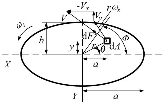
Figure 1.
Schematic diagram of the elliptical contact surface between the steel ball and the raceway.
The contact stress on the microelement dA of the contact ellipse is:
The frictional force dF acting on the microelement is expressed as:
The friction moment acting at the centre of the ellipse is expressed as:
where μ is the lubricant drag coefficient; Q is the normal contact load between the steel ball and the raceway; θ is the deflection angle of the inner ring with respect to the outer ring; and ϕ is the tightness of the steel ball and the raceway.
According to the shaft bearing force and movement relationship analysis, which can determine the heat source’s heat generation, the bearing’s total heat generation is the sum of each local heat source’s heat generation. Since the current high-speed ball bearings are designed to avoid the gyroscopic rotation of the steel ball in the groove as much as possible, ignoring the heat generation of the gyroscopic rotation of the ball in the calculation is feasible.
The spin heat generation of the steel ball is [25]:
where Ms is the friction moment of the steel ball between the guiding surfaces of the collar; ωb is the rotational angular velocity of the steel ball.
The steel ball drags the lubricant to generate heat [25]:
where Fo is the drag force of the lubricant; ωc is the rotational angular velocity of the cage.
Heat is generated by the differential sliding of the steel balls against the inner (outer) raceway [25]:
where τ is the frictional stress of the steel ball and collar groove; V is the sliding speed of the steel ball and collar raceway surface (n is i for the inner ring and n is e for the outer ring).
Heat generation by the sliding friction between the cage and ring guide surface [25]:
where DCL is the cage guiding surface diameter; FCL is the friction force between the cage and the collar guide surface; ce = 1; ωi is the angular velocity of the bearing inner ring.
Heat is generated by friction between the steel ball and the cage pocket hole [26]:
where Kc is the linear approximation constant; Zc is the pocket hole centre displacement; Kn is the deformation constant of steel ball and cage; Cp is the cage pocket hole clearance; μc is the friction coefficient of the cage; Qc is the normal force of cage pocket hole and steel ball.
The total bearing heat generation is:
3. Prediction Model and Experimental Validation
The three-dimensional model of the aero-engine rolling bearing studied in this paper is shown in Figure 2, with an inner diameter d of 130 mm, an outer diameter D of 200 mm, a number of balls Z of 19, a ball diameter Dw of 22.225 mm, and an initial contact angle α0 of 32.5°.
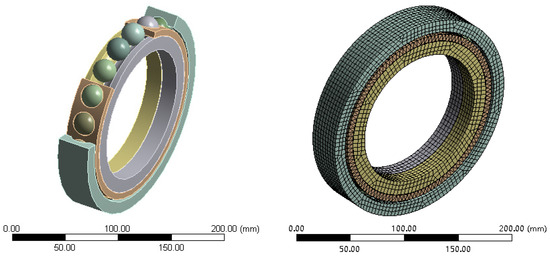
Figure 2.
Double rotor rolling bearing model and mesh model.
The bearing material has a density ρ of 7.8 × 10³ (kg/m3), a modulus of elasticity of 2.11 × 10¹⁵E (N/m2), a Poisson’s ratio μ of 0.3, a specific heat c of 482 (J/kg/K), and a thermal conductivity λ = 42.8 (W/m/K). The ambient temperature is 22 °C and the temperature of the lubricant is 95 °C. The grid cell type Solid186 is employed in the finite element simulation to mesh the inner and outer rings, the balls, and the cage of the bearings, respectively. The total number of cells is 17,707, and the total number of nodes is 59,224. The boundary conditions and rotational speeds are applied to the analysed model. Define the thermal loads and apply the calculated localised heat generation of the bearing to the surfaces of the inner ring, outer ring, balls, and cage, respectively, and the bearing heat generation and axial/longitudinal directions are taken as loads. The model is then solved using steady-state thermal analysis.
A double rotor bearing temperature rise detection device was designed for the experimental verification of the bearing temperature rise prediction model. The device is composed of a platform, a shaft system box, a spindle system, a hydraulic loading system, a lubrication system, and a detection system (see Figure 3). The loading mechanism comprises axial and radial loading, as illustrated in Figure 4. The outer ring of the bearing is connected to drive the outer shaft, while the inner ring of the bearing is connected to drive the inner shaft. The inner and outer shafts are driven by different motors, which can satisfy the simultaneous rotation of the inner and outer rings in the same direction or in the reverse direction. The axial load is applied to the inner ring of the bearing, while the radial load is applied to the outer ring of the accompanying test bearing situated in close proximity to the aerospace bearing. The bearing lubrication method employed is under-ring lubrication. The lubricant used is 4050 aviation lubricant, the inner wall of the inner ring of the test bearing is in contact with the oil supply hole, the lubricant is transported to the test bearing through the centrifugal force generated by the high-speed rotation of the shaft system, and the flowing lubricant will take away some of the heat of the bearing, which can be cooled on the bearing. The temperature detection infrared probe is fixed on the base and faces the inner ring of the test bearing. The temperature of the inner ring of the test bearing is measured by a non-contact infrared temperature sensor from Germany Miyi (micro-epsilon) thermoMETER CT.
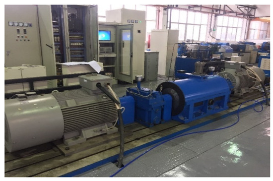
Figure 3.
Twin rotor aero-engine bearing temperature rise detection device.
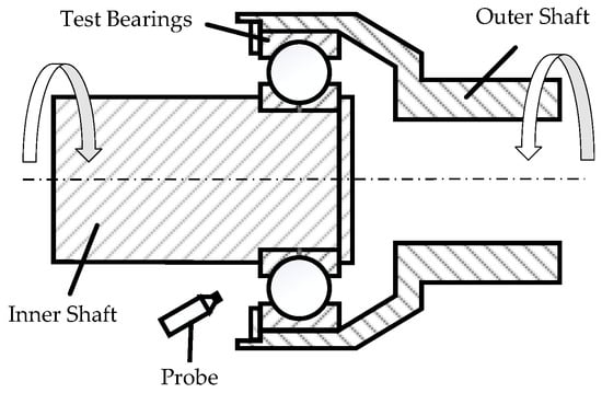
Figure 4.
Schematic diagram of bearing temperature measurement.
Five sets of tests were conducted to assess the temperature of the inner ring of the bearing under different working conditions (e.g., Table 1). The test measurements were then compared with the numerical simulation results.

Table 1.
The parameter settings for the bearing under working conditions.
Figure 5 illustrates the temperature change curve of the inner ring of the bearing, comparing the test and numerical simulation results. As illustrated in Figure 5, the overall test results of the bearing inner ring temperature measurement and numerical simulation results exhibit a consistent trend. The temperature test results are found to be lower than the numerical simulation. Under the five working conditions, the simulated temperatures are 108.77 °C, 110.89 °C, 122.27 °C, 109.38 °C, and 110.89 °C, respectively, and the test temperatures are 103.84 °C, 105.43 °C, 116.54 °C, 104.61 °C, and 104.87 °C, respectively. Therefore, the average error of the simulation model is 5.03%. The temperature of 37 °C is primarily attributable to the utilisation of fans in the test to dissipate heat around the test bearings and the sensor from the test bearings being situated at a certain distance. In contrast, the numerical simulation does not consider numerous influences. Furthermore, some parameters in the numerical simulation are idealised assumptions, which renders the numerical simulation method of bearing temperature proposed in this paper highly feasible and accurate.
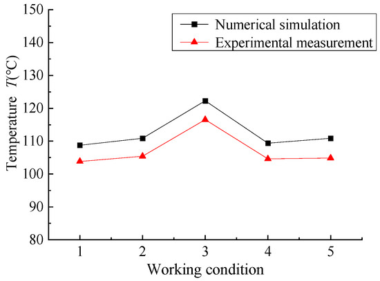
Figure 5.
The temperature of the inner ring for the bearing.
4. Analysis of Bearing Temperature Rise Influencing Factors
4.1. Influence of Rotational Speed on Bearing Temperature Rise
In order to investigate the impact of rotational speed on the temperature rise of rolling bearings in an aero-engine, the aforementioned prediction model is employed to apply varying rotational speeds to the bearings, thereby enabling the study of the temperature distribution of the bearings and the influence of rotational speed on the temperature rise of the bearings. The parameters of six working conditions were set as follows: the axial load was 15,000 N, the radial load was 8000 N, the outer ring speed was 3000 r/min, and the inner ring speed was 400 r/min, 2360 r/min, 4320 r/min, 6280 r/min, 8000 r/min, and 10,000 r/min, respectively.
Through the above working condition parameters, the heat generation curves of the bearing’s five heat sources were calculated and are shown in Figure 6. From the figure, it can be seen that all the heat sources’ heat generation increases with the increase in rotational speed. The spin heat generation is the largest and most affected by the rotational speed. The heat generation of lubricating oil drag, ball and cage friction, ball and ring differential sliding, and cage and guide surface friction heat generation are relatively small, and the growth rate is smoother. This is because with the increase in the inner ring speed, the spin component of the contact point between the steel ball and the raceway of the collar is increased, and the linear velocity difference between the contact surface of the steel ball and the raceway of the collar is also increased. In addition, the inner ring speed is increased from 400 r/min to 2360 r/min, and all heat sources’ heat generation is reduced. This is because the bearing outer ring speed of 3000 r/min and inner ring speed of 2360 r/min are closer to the spin angular velocity at this time, resulting in a reduction in spin heat generation, a small difference in the linear velocity of the steel ball and the collar, and a reduction in the sliding between the steel ball and the raceway, so the frictional heat generated by each heat source is also increased. The friction heat generation of each heat source is also reduced. When the inner ring speed increases from 4320 r/min to 10,000 r/min, the speed difference between the inner and outer ring of the bearing is big and the heat generation of each heat source increases gradually, among which the spin heat generation of the bearing increases most obviously with the increase in speed.
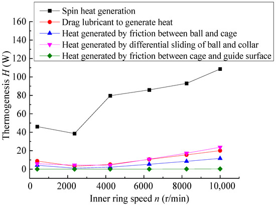
Figure 6.
Effect of rotational speed on bearing heating.
The steady-state thermal finite element method was employed to calculate and analyse the aforementioned six working conditions. The temperature distribution of angular contact ball bearings at different rotational speeds was obtained, and its temperature field cloud diagram is shown in Figure 7. It can be observed that the maximum temperatures of the bearings are 78.937 °C, 75.494 °C, 92.785 °C, 93.67 °C, 110.89 °C, and 122.27 °C, in order. The highest temperatures are observed at the contact point between the steel ball and the inner ring groove. This is due to the fact that the friction of the steel ball and the raceway, the spin friction of the steel ball, and the sliding friction are all concentrated at this point. The heat dissipation performance is not optimal at the contact point between the steel ball and the inner ring raceway, which results in the highest temperature observed at this location.
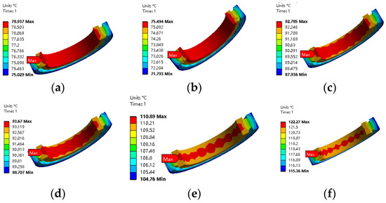
Figure 7.
The temperature nephogram of bearing under different rotational speeds. (a) Inner ring speed of 400 r/min; (b) inner ring speed of 2360 r/min; (c) inner ring speed of 4320 r/min; (d) inner ring speed of 6280 r/min; (e) inner ring speed of 8000 r/min; (f) inner ring speed of 10,000 r/min.
Figure 8 illustrates the temperature profiles of the bearings under varying rotational speed conditions. From working conditions 1 to 2, the inner ring speed increases, while the maximum temperature decreases. This is due to a reduction in the speed difference between the inner and outer ring, which in turn results in a decrease in the spin speed of the steel ball and a reduction in the spin heat of the steel ball. Consequently, the maximum temperature decreases. In working conditions 2, 3, 4, 5, and 6, the bearing temperature increases with the increase in speed. Furthermore, the volume occupied by the highest temperature part of the first, second, third, and fourth working conditions is considerable, as at this time the temperature of the lubricating oil is higher than the overall temperature of the bearing. Consequently, the heat of the lubricating oil is transferred to the bearing, and the heat is gathered on the bearing, resulting in a larger volume occupied by the highest temperature of the bearing. The fifth and sixth conditions of the highest temperature part of the volume accounted for a smaller proportion when the overall temperature of the bearing was higher than the temperature of the lubricant. In such instances, the heat of the bearing was transferred to the lubricant, which could then remove a portion of the heat, resulting in a reduction in the volume of the bearing’s highest temperature.
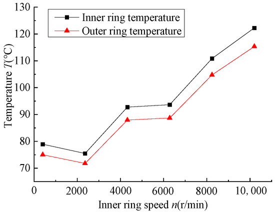
Figure 8.
The temperature of bearing under different rotation speeds.
4.2. Effect of Axial Load on Bearing Temperature Rise
The axial load of the bearing is primarily intended to guarantee the stability of the aero-engine bearing operation and to prevent the steel ball from slipping. Furthermore, it must also withstand the axial force according to the requirements of the working environment. In order to ascertain the influence of temperature distribution on the performance of angular contact ball bearings under different axial loads, a finite element analysis was conducted. Six working conditions were defined, with the following parameters: radial load of 8000 N, outer ring speed of 3000 r/min, inner ring speed of 8000 r/min, and axial load of 2450 N, 5000 N, 7350 N, 9800 N, and 12,350 N. According to the working conditions, the bearing’s axial force bearing is calculated to be 15,000 N. The heat generation of each heat source of the bearing is also calculated, with the results presented in Figure 9. This figure illustrates the bearing’s heat generation under different axial load conditions.
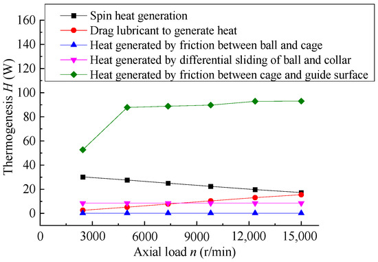
Figure 9.
Calculation results of bearing heat generation under different axial load conditions.
The temperature distribution of angular contact ball bearings under different axial loads was obtained by simulation calculation for six working conditions. The resulting temperature distribution cloud diagram is shown in Figure 10. As illustrated in Figure 10, The maximum temperature of the bearings under the aforementioned six working conditions is 94.393 °C, 108.77 °C, 109.18 °C, 109.54 °C, and 110.89 °C, respectively. Among the aforementioned conditions, it can be observed that an increase in axial force from 2450 N to 5000 N results in a notable rise in bearing temperature. This is attributed to the elevated frictional heat generation of the bearing in response to the increase in axial load, which consequently leads to an increase in bearing temperature. If the axial force is 7350 N after the increase in temperature rise is less, this is because at this time the temperature of the bearings is 105 °C, the temperature of the lubricant is 95 °C, and the flow of the lubricant takes away some of the heat. In addition, at this time, when the axial force increases, the vibration of the bearings is also reduced.
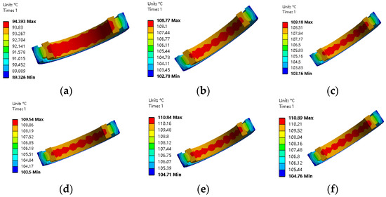
Figure 10.
The temperature nephogram of bearing under different axial forces. (a) Axial load of 2450 N; (b) axial load of 5000 N; (c) axial load of 7350 N; (d) axial load of 9800 N; (e) axial load of 12,350 N; (f) axial load of 15,000 N.
Figure 11 shows the temperature variation curves of the inner and outer rings of the bearing under different radial forces. As can be seen from the figure, the temperature of the inner ring of the bearing is higher than that of the outer ring on the whole, which is due to the fact that the heat dissipation performance of the inner ring of the bearing is not as good as the heat dissipation performance of the outer ring, and the cages of the angular contact ball bearings under study in this paper are guided by the inner ring, i.e., a part of the heat generated by friction between the cages and the inner ring is also in the inner ring of the bearing. In addition, the temperature of the bearing increases with the increase in axial force. This is because the increase in axial force will cause the bearing friction torque to increase, resulting in more heat generation in the bearing, and then the temperature increases. When the axial load increases from 5000 N to 15,000 N, the axial load changes by 10,000 N, the inner ring temperature only increases by about 2 °C, and the temperature of the inner and outer rings of the bearing changes little. When the inner ring speed increases from 8000 r/min to 10,000 r/min, the speed changes by 1960 r/min, and the inner ring temperature changes by about 11 °C. It shows that the bearing temperature rise is more sensitive to the change of speed than the axial force, and the speed plays a dominant role in the bearing temperature rise.
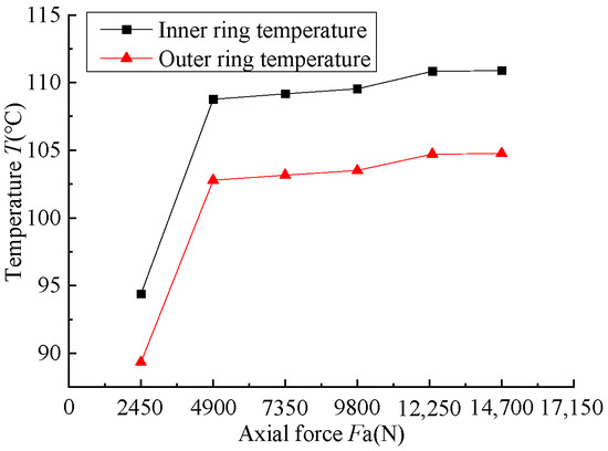
Figure 11.
The temperature of the bearing under different axial forces.
4.3. Radial Loading
To study the effect of radial load on the temperature of angular contact ball bearings, six kinds of working condition parameters are set as follows: the axial load is 15,000 N, the outer ring speed is 3000 r/min, the inner ring speed is 8000 r/min, and the axial loads are 2450 N, 5000 N, 7350 N, 9800 N, 12,350 N, 15,000 N, respectively. Calculate the heat generation of each heat source of the bearing according to the working conditions, Figure 12 shows the calculation results of the bearing heat generation under different axial load conditions. With the increase in radial load, the heat generation of each heat source increases insignificantly.
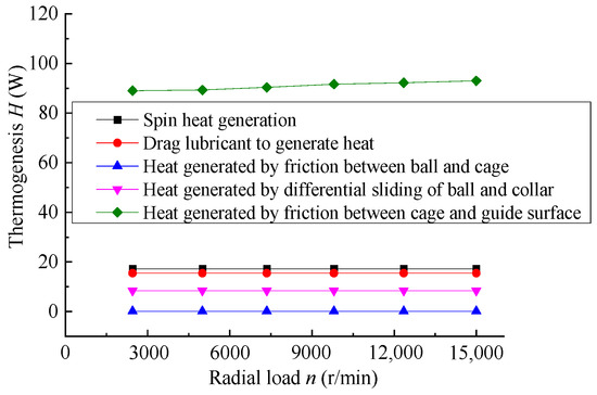
Figure 12.
The results of heat generation for the bearing under different radial forces.
The temperature distribution of angular contact ball bearings under different radial loads was obtained through simulation, and the temperature distribution cloud diagram is shown in Figure 13. It can be seen that the maximum temperatures of the bearings in the above six conditions are 109.26 °C, 109.38 °C, 109.8 °C, 110.33 °C, 110.57 °C, and 110.89 °C, respectively. The temperature distributions are also relatively similar, indicating that the changes in the radial force of the bearings do not have a significant effect on the temperature of the bearings.
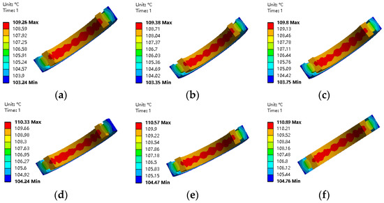
Figure 13.
The temperature nephogram of bearing under different radial forces. (a) Radial load of 2450 N; (b) radial load of 5000 N; (c) radial load of 7350 N; (d) radial load of 9800 N; (e) radial load of 12,350 N; (f) radial load of 15,000 N.
Figure 14 illustrates the temperature change curve of the inner and outer rings of the bearing in response to varying radial forces. As illustrated in Figure 13, the bearing exhibits minimal temperature change across six operating conditions, despite a 15,000 N increase in radial force. The temperature of the inner and outer rings rises by approximately 1 °C, indicating that radial force has a negligible effect on the temperature of angular contact ball bearings. This is because although the radial load increases the contact load of each steel ball, the friction heat generated also increases. However, the rotational speed and axial load of these two factors, which are triggered by the heat, are much larger than the radial load, which is triggered by the heat. Consequently, the radial load, which is responsible for the rise in the bearing temperature, has a relatively small impact on the bearing temperature.
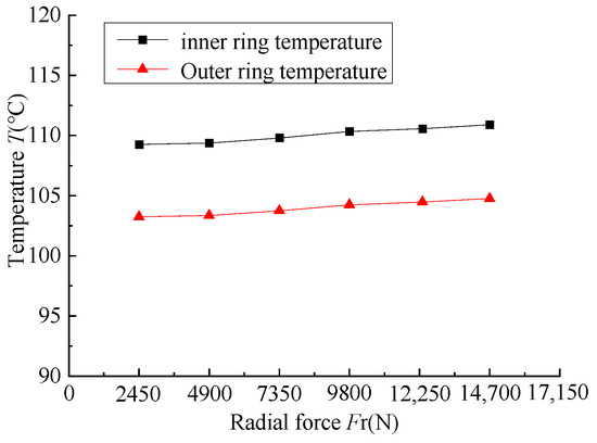
Figure 14.
The temperature of bearing under different radial forces.
5. Conclusions
In this paper, the steady-state thermal finite element method is used to study the temperature rise performance of the main shaft bearing of the aircraft engine. The prediction model accuracy is verified by the double rotor bearing device, and the influence law of rotational speed and load on the temperature rise of the bearing is analysed. The following conclusions are obtained:
- Spin heat generation is the main cause of frictional heat generation in aero-engine bearings.
- The finite element method based on steady-state heat predicts aero-engine bearing temperature rise with high accuracy.
- It can be observed that the rotational speed and axial load have a greater impact on the temperature rise. As the speed of the inner ring of the bearing increases, the temperature of the inner and outer rings rises significantly. Once the axial load exceeds a certain threshold, the temperature of the bearing increases at a slower rate. In contrast, the radial load exerts a relatively minor influence on the temperature rise.
Author Contributions
Conceptualization, K.X. and N.G.; methodology, X.M.; software, H.H.; validation, K.X. and N.G.; formal analysis, X.L.; investigation, H.H.; resources, N.G.; data curation, X.M.; writing—original draft preparation, K.X.; writing—review and editing, H.H.; visualization, X.L.; supervision, N.G.; project administration, X.M.; funding acquisition, K.X. All authors have read and agreed to the published version of the manuscript.
Funding
This research was funded by the Natural Science Foundation of Henan Province of China. (Grant No. 232300421336); the National Key R&D Program of China (Grant No. 2021YFB2011000).
Data Availability Statement
The raw data supporting the conclusions of this article will be made available by the authors on request.
Conflicts of Interest
The authors declare no conflict of interest.
Glossary of Terms
| μ | Lubricant drag coefficient | Q | Normal contact load between steel ball and raceway |
| θ | Deflection angle of the inner ring relative to the outer ring | Ms | The friction moment of the steel ball between the guiding surfaces of the collar |
| ϕ | The fit between the ball and the raceway | ωb | The rotational angular velocity of the steel ball |
| Fo | The drag force of the lubricant | ωc | The rotational angular velocity of the cage |
| τ | The frictional stress of the steel ball and collar groove | V | The sliding speed of the steel ball and collar raceway surface |
| DCL | The cage guiding surface diameter | FCL | The cage and ring guiding surface between the friction |
| Kc | The linear approximation constant | Zc | The pocket hole centre displacement |
| Kn | The deformation constant of steel ball and cage | Cp | The cage pocket hole clearance |
| μc | The friction coefficient of the cage | Qc | The normal force of cage pocket hole and steel ball |
References
- Bossmanns, B.; Tu, J.F. A thermal model for high speed motorized spindles. Int. J. Mach. Tools Manuf. 2013, 39, 1345–1366. [Google Scholar] [CrossRef]
- Kim, K.S.; Lee, D.W.; Lee, S.M.; Lee, S.J.; Hwang, J.H. A Numerical Approach to Determine the Frictional Torque and Temperature of an Angular Contact Ball Bearing in a Spindle System. Korean Soc. Precis. Eng. 2015, 16, 135–142. [Google Scholar] [CrossRef]
- Maegawa, S.; Itoigawa, F.; Nakamura, T. A Role of Friction-induced Torque in sliding friction of rubber materials. Tribol. Int. 2016, 93, 182–189. [Google Scholar] [CrossRef]
- Hinrichsen, P.F. Comment on ‘video Analysis-based Estimation of Bearing Friction Factors. Eur. J. Phys. 2021, 42, 028010. [Google Scholar] [CrossRef]
- Korolev, A.V.; Korolev, A.A. Experimental Study of the Balls and Raceways Contact Geometry Effect on the Rolling-friction Torque. J. Frict. Wear 2016, 37, 119–123. [Google Scholar] [CrossRef]
- Olaru, D.; Balan, M.R.; Tufescu, A. Influence of the cage on friction torque in low loaded thrust ball bearing operating in dry conditions. In Proceedings of the 7th International Conference on Advanced Concepts in Mechanical Engineering, Iasi, Romania, 9–10 June 2016. [Google Scholar]
- Wang, Y.S.; Zhu, H.F. Temperature Field Analysis of Bearing. Key Eng. Mater. 2011, 480–481, 974–979. [Google Scholar] [CrossRef]
- Bian, W.; Wang, Z.; Yuan, J.; Xu, W. Thermo-mechanical analysis of angular contact ball bearing. J. Mech. Sci. Technol. 2016, 30, 297–306. [Google Scholar] [CrossRef]
- Yu, J.; Zhu, S.; Yuan, W.; Chen, X.; He, L.; Guo, Q. Investigation on the friction heat generation rate of ball bearings at ultra-high rotation speed. Int. J. Adv. Manuf. Technol. 2023, 128, 57–79. [Google Scholar] [CrossRef]
- Tian, J.; Wu, Y.; Sun, J.; Xia, Z.; Ren, K.; Wang, H.; Li, S.; Yao, J. Thermal Dynamic Exploration of Full-Ceramic Ball Bearings under the Self-Lubrication Condition. Lubricants 2022, 10, 213. [Google Scholar] [CrossRef]
- Liang, Q.; Liu, X.; Du, X. Temperature field analysis of angular contact ball bearings. Lubr. Seal. 2015, 37–41. [Google Scholar]
- Xu, J.; Qu, W.; Zhao, N. Analysis of temperature field and thermal deformation of rolling bearings. Bearing 2006, 5, 1–3. [Google Scholar]
- Fu, T.; Liu, S.; Peng, J. The Steady Temperature Field Analysis of the High Speed Rolling Bearing. In Proceedings of the International Conference on Digital Manufacturing and Automation, Shinan, China, 29–30 June 2013; IEEE: Qingdao, China, 2013; pp. 1561–1564. [Google Scholar]
- Zheng, D.; Chen, W. Thermal Performances on Angular Contact Ball Bearing of High-Speed Spindle Considering Structural Constraints Under Oil-Air Lubrication. Tribol. Int. 2017, 109, 593–601. [Google Scholar] [CrossRef]
- Wen, H.X.; Wang, M.Y. Thermal Characteristics Finite Element Analysis and Temperature Rise Experiment for High Speed Motorized Spindle. Appl. Mech. Mater. 2011, 52–54, 1206–1211. [Google Scholar] [CrossRef]
- Qiu, Y.; Tan, B.; Li, D.; Jiang, H.; Feng, Y. Thermal Analysis of Rolling Bearing at Wind Turbine Gearbox High Speed End. In Proceedings of the International Conference on Renewable Power Generation, Beijing, China, 17–18 October 2015; IET: London, UK, 2016; p. 6. [Google Scholar]
- Ning, L.; Zhou, S. Technology for monitoring the internal temperature condition of rolling bearings. Bearing 2007, 25–27. [Google Scholar] [CrossRef]
- Wang, Y.; Liu, Z.; Zhu, H. Temperature field analysis of axle-link bearing. J. Mech. Eng. 2011, 47, 84–91. [Google Scholar] [CrossRef]
- Hu, X.; Chen, W. Analysis and test of thermal characteristics of angular contact ball bearings. J. Xi’an Jiaotong Univ. 2015, 49, 106–110. [Google Scholar]
- Cui, L.; He, Y.; Cai, C. Simulation and experimental study of oil-air lubrication temperature field of ball bearing for high-speed electric spindle. Mach. Tools Hydraul. 2017, 45, 15–19. [Google Scholar]
- Sun, Q.G.; Wang, Y.F.; Wang, Y.; Niu, P.; Wang, X.S. Numerical Study on Rolling Bearing Temperature Field under the Oil-Air Lubrication. Appl. Mech. Mater. 2014, 487, 580–584. [Google Scholar] [CrossRef]
- Sun, Q.G.; Wang, Y.F.; Wang, Y.; Lv, H.B. Comparing of Temperatures of Rolling Bearing under the Oil-Air Lubrication to the Spray Lubrication. Appl. Mech. Mater. 2013, 395–396, 763–768. [Google Scholar] [CrossRef]
- Ma, C.; Mei, X.; Yang, J.; Zhao, L.; Shi, H. Thermal characteristics analysis and experimental study on the high-speed spindle system. Int. J. Adv. Manuf. Technol. 2015, 79, 469–489. [Google Scholar] [CrossRef]
- Li, X.; Lv, Y.; Yan, K.; Liu, J.; Hong, J. Study on the Influence of Thermal Characteristics of Rolling Bearings and Spindle Resulted in Condition of Improper Assembly. Appl. Therm. Eng. 2017, 114, 221–233. [Google Scholar] [CrossRef]
- Chen, G.; Wang, L.; Gu, L.; Zheng, D. Thermal analysis of high-speed ball bearings. J. Aerodyn. 2007, 22, 163–168. [Google Scholar]
- Deng, S.; Jia, Q.; Xue, J. Principles of Rolling Bearing Design; China Standard Press: Beijing, China, 2014. [Google Scholar]
Disclaimer/Publisher’s Note: The statements, opinions and data contained in all publications are solely those of the individual author(s) and contributor(s) and not of MDPI and/or the editor(s). MDPI and/or the editor(s) disclaim responsibility for any injury to people or property resulting from any ideas, methods, instructions or products referred to in the content. |
© 2024 by the authors. Licensee MDPI, Basel, Switzerland. This article is an open access article distributed under the terms and conditions of the Creative Commons Attribution (CC BY) license (https://creativecommons.org/licenses/by/4.0/).