Abstract
This research investigates the micro-mechanical and tribological properties of injection-molded parts made from polypropylene. The tribological properties of polymers are a very interesting area of research. Understanding tribological processes is very crucial. Considering that the mechanical and tribological properties of injected parts are not uniform at various points of the part, this research was conducted to explain the non-homogeneity of properties along the flow path. Non-homogeneity can be influenced by numerous factors, including distance from the gate, mold and melt temperature, injection pressure, crystalline structure, cooling rate, the surface of the mold, and others. The key factor from the micro-mechanical and tribological properties point of view is the polymer morphology (degree of crystallinity and size of the skin and core layers). The morphology is influenced by polymer flow and the injection molding process conditions. Gained results indicate that the indentation method was sufficiently sensitive to capture the changes in polypropylene morphology, which is a key parameter for the resulting micro-mechanical and tribological properties of the part. It was proven that the mechanical and tribological properties are not equal in varying regions of the part. Due to cooling and process parameters, the difference in the indentation modulus in individual measurement points was up to 55%, and the tribological properties, in particular the friction coefficient, showed a difference of up to 20%. The aforementioned results indicate the impact this finding signifies for injection molding technology in technical practice. Tribological properties are a key property of the part surface and, together with micro-mechanical properties, characterize the resistance of the surface to mechanical failure of the plastic part when used in engineering applications. A suitable choice of gate location, finishing method of the cavity surface, and process parameters can ensure the improvement of mechanical and tribological properties in stressed regions of the part. This will increase the stiffness and wear resistance of the surface.
1. Introduction
Injection molding is one of the most commonly used manufacturing methods to produce polymer parts. It is characterized by a high degree of automation, high productivity, and good volumetric stability of injected parts. The polymer is exposed to thermal and mechanical effects during the injection molding cycle. The polymer experiences a transition from a molten state to a rubber, glass, or crystalline state. The final physical, optical, and mechanical properties of the injected part closely correlate with the created micro-structure.
During the melting phase of the injection molding process, the polymer experiences high shear stress, normal pressure, and a thermal gradient. The high pressure at the wall leads to the creation of a highly oriented lamellar micro-structure, commonly called the skin layer. On the other hand, the low pressure in the core leads to the creation of a spherulitic micro-structure. This difference in morphology between the surface and core has already been investigated in numerous works [1,2,3,4,5,6]. This phenomenon is commonly called skin–core morphology, which can be observed by a polarized optical microscope (Figure 1). Injection-molded semi-crystalline parts generally contain 2–5 layers [7,8,9].
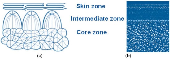
Figure 1.
Morphological structure: (a) scheme of skin–core structure; (b) optical microscope—skin–core structure.
Crystal growth occurs at temperatures below the melting point (Tm) and above the glass transition point (Tg). Higher temperatures interfere with the molecular arrangement, while lower temperatures lead to the freezing of molecular chains’ movement. Secondary crystallization can occur under Tg, although in the time scale of months and years. This process influences the mechanical properties of polymers and decreases their volume due to the more compact arrangement of polymer chains [10,11].
The growth of crystalline regions occurs in the direction of the biggest temperature gradient. In the case of a strong gradient, this growth is unidirectional and has a dendritic character. If the temperature distribution is isotropic and static, then the lamellae grow radially and create bigger quasi-spherical aggregates called spherulites. Spherulites’ size ranges from 1 to 100 µm [10]. During observation by a polarized optical microscope, spherulites create a great number of colored figures, including the typical Maltese cross [10,11,12].
The crystallization mechanism of the polymer melt is quite important for the injection molding of plastic parts. Different types of crystallization occur, for example, in extrusion during the production of fibers and films. The crystallization theory indicates that the thickness of lamellae is always less than the expected length of molecules. This means that molecules in crystals can be folded numerous times. During crystallization, only a part of the melt is deposited in the crystalline phase, while the remainder freezes in the amorphous phase, which envelops the crystalline regions. A common polyolefin is a semi-crystalline material with a relatively complex interior structure [10].
The problem of crystallization during injection molding was investigated by Le et al. [13], who focused on the influence of pressure on crystallization kinetics. The detected change in crystallization temperature enabled the identification of the pressure dependence of crystallization kinetic parameters Tm and Tg, which are used in the Hoffman–Lauritzen equation. Crystallization is the ability of a material to create rigid structures, which give the material its specific properties.
Liu et al. [14] compared the morphology of iPP samples prepared by conventional injection molding and micro-injection molding. The samples were studied using PLM, SEM, DSC, and WAXD. The results showed that micro-injected samples contained a much higher percentage of oriented shear layers. Varying crystallization in different points of the injected part was investigated by Sun et al. [15] and Pantani et al. [16], who focused on the creation of skin–core structure in the injected parts. The change in polypropylene morphology is described by the arrangement and size of spherulites in dependence on distance from the wall. The problem of crystallization was researched by more authors [17,18].
The correct setting of injection molding process parameters is a key factor not only for the stable manufacturing process but also for the expected final properties of injected parts. The most important parameters that significantly influence the entire injection molding process are injection speed, injection pressure, holding pressure, duration of holding pressure, melt temperature, and mold temperature. The individual process parameters act simultaneously and influence each other. Therefore, a change to one parameter affects other parameters [1].
Furthermore, the influence of process parameters on the mechanical properties of the injected part has been studied in numerous other publications. Wang et al. [19] focused on the effect of process parameters (especially injection speed) on the mechanical properties of micro-injected PP samples. It was found that increasing injection speed led to higher hardness, which increased more in the perpendicular direction of flow than in the flow direction. A similar study was conducted by Glogowska et al. [20], who injected samples with differing process conditions. The samples were then grinded, injected again, and their mechanical properties measured. Sykutera et al. [21] investigated the influence of process conditions on the polymer viscosity, which was measured directly in the cavity. In general practice, viscosity is measured in rheometers, but the goal of this study was to provide real values coming straight from the manufacturing process. Studies [22,23,24,25] dealt with the effect of multiple process conditions (pressure and temperature) on final flow length.
In conclusion, the submitted study focuses on the influence of flow length (distance from the gate) and process conditions on the creation of crystalline morphology (skin–core structure). The final structure affects the micro-mechanical properties of the surface layer of injection-molded polypropylene. The literary research on the problem of the influence of distance from the gate on the mechanical properties of injection-molded parts was conducted, and no existing publication concerning this topic was found. In most cases, the mechanical properties and sometimes hardness were measured only locally and subsequently taken as results for the overall part. However, there was no study that investigated the problem of varying properties along the polymer flow path of injection-molded products. The aforementioned studies were concerned with partial research, mainly with the influence of process parameters in injection molding on mechanical properties and the effect of tool quality on flow length and surface replication. Furthermore, other studies focused on changes in crystallinity, but once again, mostly locally. Some investigated properties were researched only for micro-injection molding, which is quite different from regular molding. In the field of micro-injection molding, several studies were concerned with the influence of surface roughness on the flow length of the polymer. The results of some studies were similar to macro-injection molding, although the dimensions of the final part were in the range of micrometers; thus, the effect of surface roughness on polymer flow was much greater. These results cannot be directly applied to those of macro-injection molding due to the significant difference in size. As the mechanical properties of injection-molded products are not uniform along the flow length, this research was designed to specifically target the non-homogeneity of the properties of injection-molded parts. This non-homogeneity can be influenced by numerous factors, for example, the distance from the gate, the temperature of the mold and melt, injection pressure, crystalline structure, degree of cooling, the surface of the mold, and others. This problem has a significant effect on injection molding in general practice.
2. Materials and Methods
The preparation of the experiment was inspired by the practical requirements of manufacturing injection-molded technical parts. Individual designs were checked by injection molding simulation. Information gained from the simulation was used to choose the most suitable technological parameters.
2.1. Injection-Molded Material (Polypropylene)
This research, as well as the selection of material (polypropylene), is inspired by general practice requirements, as polypropylene is commonly used for injection molding of technical parts. The testing was conducted on polypropylene, which is a semi-crystalline thermoplastic with the trade name Borealis BJ380MO provided by Borealis (Linz, Austria). The selected material is commonly used in the automotive industry, from which the request for testing properties along the flow length originated. Polypropylene is nowadays being pushed out by more expensive construction materials. On the other hand, polypropylene is still quite useful, especially due to its wide range of applications and processing parameters. The material properties were taken from the provided material sheet, as can be seen in Table 1.

Table 1.
Basic properties of injection-molded material.
2.2. Injection Molding
The test samples were prepared using the injection molding machine Allrounder 470 E 1000-290 Golden Edition, manufactured by Arburg (Losburg, Germany). The mold tempering was conducted by the oil tempering unit Regloplas 150 Smart, manufactured by Regloplas (St. Gallen, Switzerland). The process conditions were set based on values gained from the injection molding simulation and material sheet (Table 2). The test samples were manufactured as rectangular blocks with dimensions of 6 × 1 × 240 mm. The selection of injection molding parameters for this research is once again based on the requirements of industrial practice. This research is only a part of extensive work regarding the problem of the polymer flow path and its final properties. The chosen injection molding parameters for this research were taken closer to the lower boundary of recommended parameters given by the manufacturer with regards to the economic perspective of the length of the injection molding cycle (melt temperature 215 °C, mold temperature 30 °C). The recommended melt temperature range is 215–255 °C, and the mold temperature is 30–50 °C.

Table 2.
Technological parameters of the injection molding process.
The cavity of the testing injection mold was in the shape of four grooves with varying lengths, which were determined according to previously conducted injection molding analysis that focused on the estimation of process parameters that could lead to the complete filling of the mold. The length of individual cavities was 208 mm, 158 mm, 68 mm, and 38 mm (Figure 2a). The cavity had a rectangular cross-section with a dimension of 6 × 1 mm and a length of 208 mm (Figure 2b). The connectivity of the cavity with the runner was ensured by a cold slug, which was rotated by 90° for each length. The shape plates were changeable and fit into a universal frame. These plates were tempered through drilled channels.
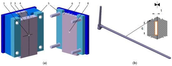
Figure 2.
Injection mold cavity: (a) Test mold, 1—sprue holder, 2—mold plate, 3—ejection plates, 4—tempering system right, 5—mold frame, 6—test mold plate, 7—tempering system left, 8—sprue insert; (b) cross-section of mold cavity.
The cavity of the injection mold was manufactured by fine milling, as the required quality of the surface was in the range of Ra 1.6 µm to Ra 2.2 µm. The conditions of the manufacturing were set according to the requirements.
2.3. Injection Molding Simulation
The injection molding simulation was performed in order to provide data that could be compared with real results and to help with the setting of the process parameters. The simulation was performed in MoldFlow Synergy, which was made by Autodesk (San Rafael, CA, USA). The conditions were set according to the material sheet in a way that closely resembled conditions during injection molding.
The material for simulation was selected from the software database, which offers the same type of polypropylene (Borealis BJ380MO) that was used to produce the injection-molded specimens. The parameters of the selected material can be seen in Table 3.

Table 3.
Basic properties of polypropylene (Borealis BJ380MO).
The imported model was hatched by a 3D network made of 4-sided bodies (Figure 3), which provided an adequate representation of the part in its entire volume and subsequent display of results throughout the entire thickness of the part. The gate was made in the form of a conical sprue. The generated 3D network was subsequently checked for all requirements, and then the simulation was conducted (Table 4).
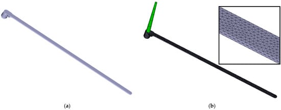
Figure 3.
(a) Imported 3D model; (b) meshed model includes gate system.

Table 4.
Properties of mesh.
Figure 4 displays the tempering system and the mold block. The trajectory of tempering channels, including the inlet and outlet of the tempering medium, is derived from the real mold concept. The core, cavity, and other mold plates were simplified as blocks for the sake of simulation. Geometry defined in this way was subsequently also hatched by a 3D network and then checked. After this step, it was necessary to set all other conditions of the simulation, which can be seen in Table 5.
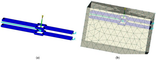
Figure 4.
(a) Cooling system; (b) mold block.

Table 5.
Process settings for simulation.
After the simulation was started, all necessary calculations ran according to pre-set conditions. The complex Moldflow analyses provided numerous important results that were significant for the visualization of events taking place in individual phases of the manufacturing cycle and allowed the evaluation of qualitative parameters of the product. The goal of the simulations was to analyze the time of filling, injection pressure, and orientation in the skin–core layer. The results of these analyses provide important information for the stabilization of the injection molding process and the prediction of polymer behavior in the cavity.
2.4. Tribological Properties
Tribological properties were measured using the MicroCombi tester MCT3 from Anton Paar (Graz, Austria). The measurements were carried out using the micro-indentation test, which allows the coefficient of friction and abrasion resistance of the tested surfaces to be determined. The principle of this measurement is based on the straightforward movement of the indentor (Rockwell cone) with a tip angle of 120° and a tip radius of 100 µm along the surface of the test specimen. The process parameters can be seen in Table 6. Tribological properties were measured on a MicroCombi tester, which was also used in the works of other authors [26,27].

Table 6.
Measurement parameters for tribological properties.
Ahead of the process, the indentor moves along the surface with a defined force to initiate the measurement device. Following the initiation, the indentor penetrates the test sample with normal force Fn, which leads to material deformation and the creation of an imprint. The sensors record the friction force Ft, which is proportional to the normal force, and a so-called pre-scan, which is concerned with the surface profile of the test sample before the penetration depth Pd (penetration depth) and post-scan of the imprint Rd (residual depth), which are important for polymer relaxation evaluation. Valuable information about the tribological properties of the material can be obtained from the difference in profile depths (Pd − Rd). Finally, the critical loads can be accurately measured using the acoustic emission AE and friction coefficient µ. Figure 5 shows a schematic diagram of the micro-tribometer.
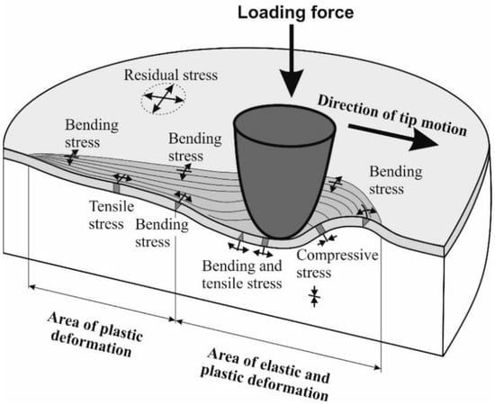
Figure 5.
Schematic diagram of the micro-tribometer.
2.5. Micro-Mechanical Properties
The micro-mechanical properties measurement was conducted by depth sensing indentation (DSI) on a Micro-Combi tester (MCT3) manufactured by Anton Paar (Graz, Austria).
A four-sided diamond pyramid with a top angle of 136° (Vickers indentor) was used as the indenting body. The measurement was conducted by the DSI method (depth sensing indentation), and the data gained were evaluated by the Oliver and Pharr method. The measurement was conducted according to the ČSN EN ISO 14577 standard [28]. Two loading forces were used to observe the changes in the structure (skin–core layer). The use of loading force 1 N led to a 20 µm depth of indentation, while the application of 5 N led to a 100 µm depth of penetration. The measurement parameters can be seen in Table 7. Since it was a micro-hardness measurement, which works with low indenting force with depth in the range of µm, the only evaluated parameters were indentation hardness, indentation modulus, and indentation creep.

Table 7.
Parameters of mechanical property measurement.
In order to determine mechanical properties and structure changes at varying distances from the surface, the test samples were cut, fixed in resin, and polished. The test samples prepared in this way can be measured in a direction perpendicular to the surface. Individual cuts were conducted in five sections evenly distributed along the flow direction (gate location 0 mm, and then 79 mm, 158 mm, 198 mm, and 220 mm from the gate).
As described in the ISO 14577 standard [28], the following parameters were evaluated: indentation hardness, modulus, and creep. The calculation of the individual values has been carried out using the Oliver and Pharr method (Figure 6).
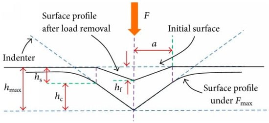
Figure 6.
Schematic representation of the indentation processes shows the decrease in indentation depth during loading (according to Oliver and Pharr).
Indentation hardness (HIT) can be defined as the ability of a material to resist plastic deformation. Indentation hardness HIT (Equation (1)) is expressed by the ratio between the applied load Fmax and the contact area (Ap) between the indenter and the specimen at the maximum depth and load. The contact area Ap (Equation (2)) is specified by the shape constant of the indentor (24.50 for the Vickers indenter) and the depth of contact of the indentor with the test specimen hc [29,30].
Another material property that can be obtained from indentation testing using the DSI method is the indentation modulus EIT (Equation (3)). The indentation modulus EIT is comparable with Young’s modulus of the material. In general, the indentation modulus can be determined from the slope of the tangent line used to calculate the indentation hardness HIT. As described in the ISO 14577 standard, the reduced modulus, Er, is used to account for the fact that the elastic displacements occur in both the indenter and the sample. The instrumented elastic modulus in the test material, EIT, can be calculated from Er (Equation (5)). The calculations involve Poisson’s ratio (vs), which is usually between 0.2 and 0.4 for metallic materials and 0.3 and 0.4 for polymeric materials [29,30].
The plane strain modulus E* is calculated from the following Equation (4), where Ei is the elastic modulus of the indenter (diamond 1141 GPa), Er is the reduced modulus of the indentation contact, and vi is Poisson’s ratio of the indenter (0.07) [29,30].
Reduced modulus Er is calculated from the following Equation (5), where C is contact pliability and Ap is contact area, for the Vickers indentor [29,30].
Indentation creep is defined as the relative change in the indentation depth while the applied load is kept constant. It is defined in the ISO 14577 instrumented indentation standard as CIT (Equation (6)), where h1 is the depth at the beginning of the creep test, and h2 is the depth at the end of the creep test [29,30].
2.6. Differential Scanning Calorimetry (DSC)
The behavior of the tested samples during melting and solidification was observed by the differential scanning calorimeter DSC Q20 (TA Instruments, New Castle, DE, USA). The weight of the sample was 6 mg, which was prepared by a microtome device. The speed of heating and cooling was set to 10 °C/min. The DSC measurement was divided into two parts. The first part contained primary heating from T0 to T1, followed by staying at constant temperature (isotherm 1 min), cooling to T0, staying at constant temperature (isotherm 1 min), and heating to T1. The observed properties were evaluated during the first heating phase. The first phase of heating was observed in order to determine the changes induced by the previous processing of the material (injection molding). The first phase of heating allowed the observation of the history of polypropylene’s processing and its influence on the structure and macromolecules, while the second phase no longer showed this history.
Polypropylene Borealis BJ380MO is not 100% crystalline; its crystallinity is around 44%, as reported by the authors in the [31] article. The crystallinity must be recalculated according to Formula (7). Crystallinity was calculated from the heat flow by the following equation:
where Xc is crystallinity (%), ΔHm is heat flow (J/g), and ΔHm100 is heat flow for 100% crystalline polypropylene (207 J/g), which was found in the literature [32].
The process parameters of the DSC test for the determination of the crystallinity of polypropylene were set according to previously conducted studies [32,33,34,35,36]. The authors of these publications used DSC to determine the crystallinity of polypropylene and demonstrated the use of this method to find the crystallinity with sufficient sensitivity.
2.7. Polarized Optical Microscope
Tested samples were cut into slices with a 20 µm thickness in the transverse direction on a rotational microtome Leica RM 2255 (Deer Park, IL, USA). These cuts were examined by a polarized optical microscope, which helped in determining the changes in structure along the cross-section of the tested material.
3. Results
The goal of the experimental work was to find the influence of gate distance on observed parameters such as micro-mechanical properties (indentation hardness, indentation modulus, and indentation creep) and morphology. These properties were measured on the surface layer.
3.1. Injection Molding Simulation
The process conditions were set according to the MoldFlow analysis. Figure 7 shows the results of filling time (Figure 7a), injection pressure (Figure 7b), and skin–core structure (Figure 7c,d) for plate-shaped samples. The results were used not only to set the process parameters of injection molding on the machine itself but also to show the behavior of the polymer in the cavity and predict the orientation created in the skin and core layers. As can be seen in the results of layer orientation, a highly oriented layer was created in the surface layer, while an un-oriented structure was created in the core. This orientation of the skin–core layer has a significant effect on final properties, which can be seen in the results.
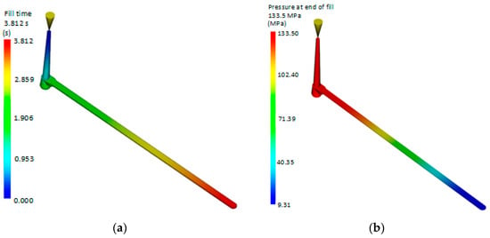
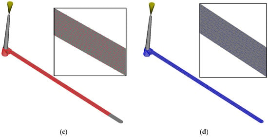
Figure 7.
Results of simulation analysis: (a) filling time; (b) injection pressure; (c) core layers; (d) skin layers.
The orientation of the skin result (Figure 7d) provides a good indication of how molecules will be oriented on the outside of the part, showing the average principal alignment direction for the whole local area at the end of the filling. The magnitudes of these vectors are normalized to one and are displayed multiplied by the given scale factor. Skin orientation is determined by the velocity direction when the melt front first reaches a given location. The orientation of the skin result is useful for estimating the mechanical properties of a part. For example, the impact strength is typically much higher in the direction of molecular orientation at the skin. The skin orientation generally represents the direction of strength. For plastic parts that must withstand high impact or force, the gate location can be designed to give a skin orientation in the direction of the impact or force.
The orientation at the core result (Figure 7c) provides a good indication of how molecules will be oriented at the part core, showing the average principal alignment direction for the whole element. The core orientation for each triangular element is perpendicular to the velocity vector before the center layer reaches the transition temperature. This is the most probable orientation in the core region of a part. The other possible orientation is in the direction of the velocity vector. Core fiber orientation may be different from skin fiber orientation. Because the melt freezes very quickly when it contacts the mold for the first time, the velocity vector provides the most probable molecular orientation at the skin.
3.2. Tribological Properties
Using the scratch test, it is possible to examine the tribological properties of the surface layer of the tested injection-molded polypropylene, such as frictional force (Figure 8a), acoustic emission (Figure 8b), friction coefficient (Figure 8c), and surface profile after indentation (Figure 8d). The tribological properties were examined at five locations, which were specified at different distances from the point of the injection gate to the end of the part. The measured distance X was determined to be 5 mm for all samples. These tests can help with the prediction of surface resistance to abrasion and thus complement measurements of micro-mechanical properties such as hardness, modulus, etc.
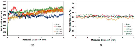
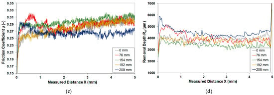
Figure 8.
Tribological properties: (a) frictional force; (b) acoustic emission; (c) friction coefficient; (d) removal depth.
The results of tribological tests show that the highest values of observed properties, e.g., friction force and friction coefficient, were found at a distance of 154 mm. Acoustic emission showed similar values for all measured distances. On the contrary, observed tribological properties improved at the gate (0 mm) and at 208 mm from the gate, where the lowest values of tribological properties were measured. For example, the friction coefficient showed a value of 0.27 at a distance of 0 mm (start of the part), 0.30 at a distance of 154 mm (center of the part), and 0.25 at a distance of 208 mm (end of the part). The difference in the coefficient of friction between the individual points of the part was up to 20%.
As the results show, the tribological properties of injection-molded PP are not homogeneous along the length of the part, but due to different flow conditions, the tribological properties change, which is reflected in an increase in the wear resistance of the surface layer. This enhancement was caused by structural changes that directly impacted micro-mechanical properties.
3.3. Micro-Mechanical Properties of Surface Layer
This part was focused on the observation of micro-mechanical properties (indentation hardness, indentation modulus, and indentation creep) in the surface layer at various distances from the gate. The depth of mechanical property measurement reached approximately 20 µm (Figure 9a,c,e). The structures and micro-mechanical properties deeper in the test samples were measured with a loading force of 5 N, which penetrated up to 100 µm (Figure 9b,d,f). This measurement was supplemented by morphology (crystallinity) observations and the thickness of the skin layer.
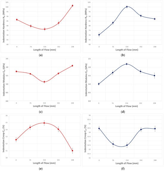
Figure 9.
Influence of measurement depth and distance from the gate on mechanical properties: (a) indentation hardness—1 N (penetration depth 20 µm), (b) indentation hardness—5 N (measurement depth 100 µm), (c) indentation modulus—1 N (depth of measurement 20 µm), (d) indentation modulus—5 N (depth of measurement 100 µm), (e) indentation creep—1 N (depth of measurement 20 µm), (f) indentation creep—5 N (depth of measurement 100 µm).
The test samples prepared by injection molding demonstrated that distance from the gate significantly affects mechanical properties, such as indentation hardness and modulus. The hardness decreased with distance from the gate, up until the measurement point located at 154 mm. The total decrease was 15%. Further measurement points demonstrated the opposite trend, and the values measured at the end of the sample were 17% higher than at the gate and 34% higher than at the middle (154 mm) (Figure 9a).
The indentation modulus (Figure 9c) characterizes the rigidity of the part, and it can be determined from the de-loading phase of the indentation cycle. The reported results (20 µm) of the indentation modulus display similar tendencies to indentation hardness. When compared, the modulus values measured at the end of the sample were 24% higher than at the gate. On the other hand, the indentation modulus measured in the middle of the sample was 55% smaller than at the gate.
Indentation creep is another important property of the polymer part, as it characterizes the resistance of the material against long-term strain. Most polymer parts are used in applications that are exposed to continuous and long-term strain. The results of indentation creep show that flow path and flow length have a significant effect on the values of indentation creep (Figure 9e). Once again, the indentation creep decreased by 20% until the measurement point was located at 154 mm and then improved by 36%. The indentation creep value measured at the end of the sample was 14% higher in comparison with the gate.
The measurement of the mechanical properties of the surface layer at individual distances from the gate shows that the length of polymer flow and subsequent cooling of the polymer within the cavity have a significant influence on the mechanical and morphological properties of injection-molded products. Within the surface layer, the mechanical properties (indentation hardness, indentation modulus, and indentation creep) were not homogenous along the flow direction. The maximum values were measured at the gate (0 mm) and at the end of the injection-molded product (208 mm), while the minimum values were measured at the middle of the sample (154 mm), which resulted in the decline of mechanical properties. The measurements at a penetration depth of 100 µm displayed an opposite trend in values of indentation hardness. An increasing indentation hardness was observed, up to 154 mm from the gate. The increase in indentation hardness from the gate (0 mm) to the distance of 154 mm was approximately 43%. On the other hand, a significant decrease in mechanical properties, up to 15%, was observed at the end of the sample. When comparing the gate and end of the sample, it can be seen that there was a 24% increase in indentation hardness between these points. (Figure 9b).
The values of indentation modulus in 100 µm depth once again demonstrated an opposite trend to those found in 20 µm. Towards the center of the part, an increasing trend in values of the indentation modulus was observed. The difference between the gate (0 mm) and middle (154 mm) was 120%. Towards the end of the part, the indentation modulus decreases by 47% (Figure 9d).
Values of indentation creep in 100 µm displayed improvement towards the center of the part by up to 18%. Towards the end of the sample, the values of indentation creep were the same as those measured in the gate location (Figure 9f).
An opposite trend in mechanical properties was observed in deeper layers of the material in comparison with the surface layer. This trend was also dependent on the distance from the gate. An increasing trend in mechanical properties was observed in test samples along the flow direction, i.e., the mechanical properties rose from the gate up to 154 mm from the gate and, on the other hand, declined from 154 mm from the gate up to the end of the specimen.
The observed changes in mechanical properties are given by the distribution of the crystalline phase and the change in the arrangement of the structure (size and shape of spherulites) along the flow direction. This is significantly influenced by the magnitude of holding pressure and mold temperature. The aforementioned findings correspond with the behavior of polymers within the cavity, in which the polymer experiences fountain flow, i.e., the polymer moves from the middle of the cavity to the cold surface of the mold, where the polymer melts quickly, cools down, and creates a frozen layer. As is described in the following sub-paragraph, property changes at varying distances from the gate were caused by different skin layer thicknesses along the part. Molecules in this layer are more oriented, and the total content of the amorphous phase is higher than in the core. The thickness of the skin layer is lowest at the gate and at the end of the sample, while a thicker skin layer can be found in the middle of the sample.
3.4. Micro-Mechanical Properties across Sample Depth
In this sub-paragraph, the influence of gate distance in varying depths of the test sample on the mechanical properties was observed. The measurements were conducted on cut slices of test samples picked out at differing distances from the gate. The goal of this measurement was to prove varying mechanical properties in the cross-section of the test samples. The presentation of results was conducted using 3D columns in order to clearly display the trends of mechanical properties at two levels (along the specimen and in individual depths). The average values and standard deviation presented in these graphs can be seen in Table 8, Table 9 and Table 10.

Table 8.
Statistical parameters of indentation hardness (MPa).

Table 9.
Statistical parameters of indentation modulus (GPa).

Table 10.
Statistical parameters of indentation creep (%).
The measured results indicate that the distance from the surface has a significant influence on mechanical properties. The results from all gate distances show that the indentation hardness is significantly higher at the center of the part than at the surface. These differences were, for example, 17% at the gate and 33% at 152 mm from the gate (Figure 10a). A similar trend was measured for the indentation modulus, which rose towards the center (Figure 10b). The difference between the surface at the gate and in the middle of the sample was 24%, while it was 53% at 0.5 mm depth. For indentation creep, a similar improvement between surface and center was measured, up to a 39% increase (Figure 10c).
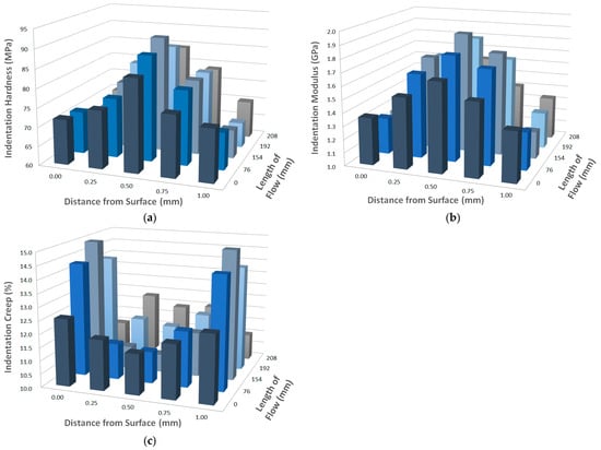
Figure 10.
Influence of distance from the surface of the test sample and gate distance on mechanical properties: (a) indentation hardness; (b) indentation modulus; (c) indentation creep.
These results confirm the findings discussed in Section 3.2 and Section 3.3 while also showing that the polymer structure is not the same across the entire cross-section of the tested sample.
3.5. Surface Quality
Results of surface replication (Figure 11 and Figure 12) indicate that the surface quality of injection mold replicates on test samples to a limited degree and differently at individual points of the part. Milled surfaces displayed deviances in surface qualities that could be caused by the direction of milling. According to the results, the surface quality changes over the course of the flow length. The surface quality of the test sample near the gate was Ra 1.1 µm, while the mold had 2.1 µm. The surface quality at the end of the test sample (225 mm from the gate) was similar to the gate. Surface qualities at gate distances of 77 mm and 154 mm increased to 1.4 µm in comparison with mold, which displayed Ra 1.8 µm. After this measurement point, surface quality decreased all the way towards the end. The surface quality at the gate was Rz 7.5 µm for the test sample and Rz 11 µm for the injection mold, while at the end, the surface quality was Rz 4.2 µm at the gate and Rz 10.5 µm for the mold.
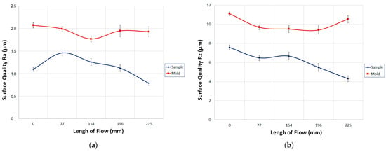
Figure 11.
Influence of surface replication at varying distances from the gate: (a) surface quality Ra, (b) surface quality Rz.
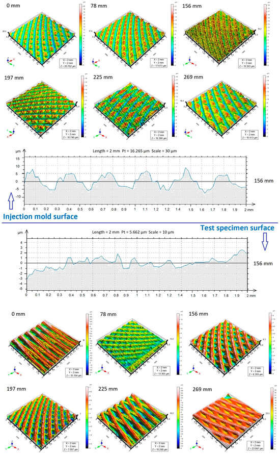
Figure 12.
Replication of the tool’s surface on the test sample—Ra 1.6 µm.
The surface quality of the mold replicated with better surface quality on the test sample. The replication can be influenced by numerous factors, such as injection pressure, mold temperature, enclosed air, etc. The main parameter that influences surface replication is pressure drop, which manifests in a decrease in surface quality from 154 mm from the gate all the way to the end of the test sample.
The surface profile, as shown by the 3D surface image (Figure 12), shows that the difference in replication is significant. During flow, the polymer failed to fill the biggest irregularities in the mold due to the temperature profile. For all measured points, a positive trend in surface replication was measured. The results of the tool’s and test sample’s 2D surface quality profiles indicate that the highest irregularities of the tool surface were not replicated on top of the test sample, which manifested in differing surface quality at individual measurement points. These tendencies were most likely influenced by the pressure drop in the cavity, enclosed air, and melt temperature.
3.6. Influence of Gate Distance on Polypropylene Structure
This part served for the observation of morphology changes that occurred during the filling and cooling of test samples in the cavity. The individual structural changes were measured at the same distances from the gate as the mechanical properties.
3.6.1. Polarized Optical Microscope
The changes in surface layer (skin) thickness were observed along the length of the part by a polarized optical microscope. Microtome cuts with 20 µm thickness were made at individual distances from the gate. During injection molding, the polymer is forced to flow towards the cold surface of walls, where it cools and solidifies; this is called the fountain flow. This type of layer displays a high degree of orientation (Figure 13), which directly translates to specific polymer properties.
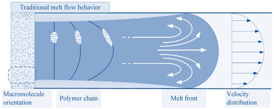
Figure 13.
Mechanism of structure creation during injection molding.
Figure 14 illustrates cross-sectional views of different morphological structures on the surface and in the middle of an injection-molded tensile sample. As can be seen, the morphological structure changes with the thickness of the injected samples. The structure with high orientation appears in the skin layer, and the spherulitic structure with essentially no preferred orientation appears in the core layer. It has been reported that in the skin layer, because of the high shear stress and shear strain, the extended polymer chains lead to extended chain crystals. In the core layer, because of the absence of shear, the random polymer chains lead to lamellar, chain-folded crystals, and, finally, spherulites. Hence, the structure is related to flow-induced crystallization, and the spherulitic structure is related to quiescent crystallization.
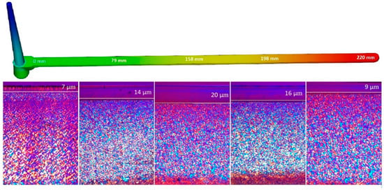
Figure 14.
Changes in surface (skin) layer thickness at various distances from the gate.
As can be seen in Figure 14, the skin layer is not the same along the injection-molded part. The thickest skin layer can be found at gate distances of 158 mm in the sample (up to 20 µm), while the thinnest skin layer can be found at the end of the part. These differences in the thickness of the highly oriented layer are due to differences in the intensity and velocity of cooling of the polymer during mold filling. This is reflected in the resulting skin layer. The high orientation of macromolecules in the surface layer prevents the PLM light from passing, as seen in Figure 14. This surface layer has a significant influence on the varying mechanical properties of the part.
3.6.2. Differential Scanning Calorimetry
This sub-paragraph deals with observed changes in crystallinity (heat flow, Table 11) due to differing distances from the gate (Figure 15). Results of surface layer crystallinity indicate that the highest content of the crystalline phase is near the gate and at the end of the part. Towards the middle of the sample, the content of crystallinity decreases (Figure 15b). Crystallinity in the core layer (Figure 15d) points towards the opposite trend as observed in the skin layer. The highest crystallinity was measured at the center of the sample (158 mm). These results agree with the mechanical property measurements, which followed a similar trend.

Table 11.
Heat flow ΔHm (J/g).
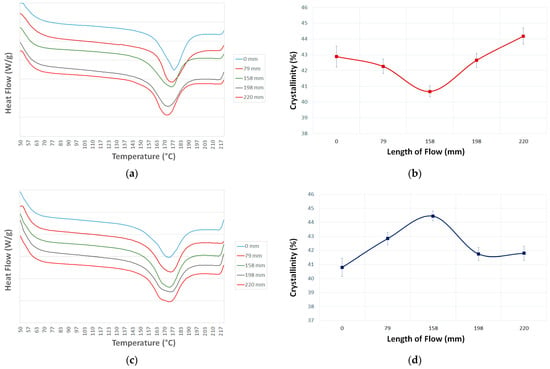
Figure 15.
Measurement of crystallinity: (a) DSC characteristic—skin layer; (b) crystallinity of surface (skin) layer; (c) DSC characteristic—core layer; (d) crystallinity of core layer.
It is obvious from the DSC measurements that the crystalline phase content, and thus micro-mechanical properties, change along the flow length (Figure 15). These changes correspond with changes in micro-mechanical properties. The crystallization rate is not uniform during polymer cooling, and so different structures are created, including shear-oriented lamellae and spherulites. These structures provide different mechanical properties.
The injection molding process is sensitive to polymer temperature, especially during cooling, during which the molecular chains orient in the direction of flow. In the core layer, the longer chains can remain in a stretched-out state, while the shorter chains are oriented randomly during filling. In the final structure, the prevalence of spherulites is significant.
The aforementioned results correspond with polymer behavior in the cavity, where the polymer flows by fountain flow from the middle towards the cold surface of the walls. The polymer melts, cools rapidly at the wall, and creates a solid layer. This significant cooling imposes a high degree of elongation orientation in the skin layer, while in other layers, the molecules have more time to relax. The combined effect of solidification and relaxation creates several regions with varying degrees of orientation (surface layer, shear layer, and core). The surface layer solidifies quickly with next to no relaxation and contains highly oriented molecules. This is caused by elongation deformation brought on by fountain flow. The degree of orientation corresponds with the flow length at the moment the mold is filled. The final orientation along the flow length is strongly affected by the holding pressure phase, as mentioned above. The degree of orientation and especially differences in crystalline morphology in individual layers of a part have a significant effect on research properties.
In technical practice, a part is generally understood to have uniform properties along its entire length. Although this does not correspond with reality, the properties can vary at different points. The findings of this work show that it is not possible to view one part as homogenous (from the mechanical and morphological point of view), but it is necessary to focus on specific points of the injected part. A suitable choice of gate location and process conditions, such as holding pressure or mold temperature, can result in improved local properties. This can be especially beneficial in parts with local straining, as they can be modified without requiring more expensive material.
4. Discussion
This research aims to explain the tribological and mechanical behavior of polypropylene to support the beneficial introduction of those materials in actual applications. Generally, the designers have to take into consideration a set of tribological and mechanical parameters, not only one, including friction coefficient, wear, contact durability related to application, and the hardness of the surface. Polymers are very promising materials to be used for rubbing components in machines and devices. However, the selection of materials with appropriate tribological and mechanical properties is critical. Understanding the frictional and wear mechanisms controlled, in particular by the intensive and decisive transfer of material during the operation of polymeric tribosystems, is a very important task for tribologists. Low cost, corrosion resistance, damping of vibrations, ability to adapt to work in the presence of contamination, and many other advantages of the use of polymers in sliding (as well as rolling) systems open up a very interesting research area for tribology.
This research is part of large-scale research based on sub-parts from practice, where it has been found that the mechanical and tribological properties are not the same along the length but vary at different points in the injection-molded products. Based on this finding, test molds with different lengths, shapes, and cross-sections (straight cavity (Figure 2), spiral cavity, and cavity in the form of a tensile test body) were designed, in which the surface of the cavity was manufactured by different technologies with manual surface roughness (milled cavity Ra 1.6 µm, grinded cavity Ra 0.8 µm and Ra 0.45 µm, polished cavity Ra 0.1 µm, and coated cavity TiB2). Subsequently, the tested materials (PP, PA6, etc.) and conditions of injection molding (melt temperature in the range of 215 to 255 °C, mold temperature 30–50 °C, and injection pressure 20–80 MPa) were changed. Based on these variations, it is possible to declare that the results demonstrated in this work can be used even in the case of different mold cavities and surfaces, materials, and processing parameters. The main condition is that the product has a shape with a longer flow path. Then, it can be said that the product’s properties are not the same along the length of the part and are influenced by numerous factors that can be affected during injection molding. These changes have a significant effect on the distribution of the skin–core layer and, thus, the mechanical and tribological properties.
These findings are crucial for technical practice and can be used in the injection molding of polymer materials in the industry. Currently, in technical practice, the view of an injection-molded product’s properties is quite simplified, with no regard for the non-homogeneity along the flow length. Based on the findings of this study, mold or process parameters can be modified to improve the properties of injection-molded products. The areas of the product that are more mechanically strained can be locally reinforced by these modifications. The biggest influence on mechanical and tribological properties along the flow is exerted by gate placement, which is closely followed by polymer cooling in the cavity. A local change in mold temperature in concrete areas could lead to significant changes in mechanical properties. Due to the aforementioned effects, there could be a change in the morphological structure of the polymer in the specified area, which could then manifest as changed mechanical and tribological properties. This publication opens new opportunities for modification of the injection molding process that could be used for complex applications with specific requirements.
This knowledge was applied to a practical part, which was a headlamp bezel, where the clamping points were subject to cracking. By changing the location of the injection gate, changing the melt and mold temperature, and modifying the tempering circuit, the mechanical properties were improved (up to 38%). This was achieved by more intensive cooling in the problem area and also by changing the injection gate location so that the polymer path was not too long, thus moving the stronger spot into the clamping point area. It is also possible to improve these properties by applying a TiB2 coating to the mold cavity, which will improve the flowability of the polymer and increase the mechanical properties. As the following research shows, the application of the coating increased the mechanical properties by 33%.
The tribological, mechanical, surface, and morphological properties of the injection-molded polypropylene samples were investigated. It was found that the injection molding process and the gate location can be used to increase the abrasion resistance of polypropylene. We have also found that the relationship between tribological characteristics and morphological characteristics (skin–core layer, crystallinity, etc.) has a major influence on the final product. This can be attributed to the injection molding process, the location of the injection gate, and the behavior of the polymer during cooling, resulting in a higher surface resistance of the polypropylene. Thus, it can be concluded that in order to achieve optimum tribological and mechanical properties of injection-molded polypropylene, it is necessary to monitor the morphological properties of the material with a focus on crystallinity, which has a major influence on the aforementioned properties.
Gained results of varying properties along the flow path of injection-molded properties change the view of polymer behavior during injection molding and can have a significant effect on technical practice. For a complex description of this behavior, further investigation is necessary, especially with a focus on other polymer materials or process parameters.
5. Conclusions
This work deals with the influence of gate distance on the properties of injection-molded polypropylene parts. The importance and current research in the area of tribological and mechanical properties of injection-molded product surfaces have been extensively reviewed to provide an understanding of their importance and benefits relating to their use in industry. The effect of the technology itself, manufacturing processes, and related process parameters on the tribological properties of injection-molded polypropylene has been discussed in terms of the complex behavior of the polymer surface. Understanding the mechanisms of friction and wear on an injection-molded part is very important for designers and, when correlated with mechanical properties and especially morphological properties, opens up a very interesting area of research in the field of tribology. Prepared test samples were measured for their micro-mechanical properties (indentation hardness, indentation modulus, indentation creep), tribological properties (friction force, acoustic emission, friction coefficient), surface quality, and structural changes.
The test samples showed heterogenic behavior along the flow length as well as within individual depths of the part. In the surface layer (depth of measurement 20 µm), the mechanical properties decreased from the gate to the middle of the sample (158 mm). This decrease was in total 15% for indentation hardness and 55% for indentation modulus. The tribological properties also showed similar behavior to the micro-mechanical properties. The coefficient of friction has its maximum value at the beginning and end of filling and decreases towards the middle distance of filling. The coefficient of friction increases significantly with crystallinity. The difference in the tribological properties (coefficient of friction) between the individual points of the part was up to 20%. Towards the end of the sample, an opposite trend was observed. Deeper in the surface layer (100 µm), an opposite trend was found for mechanical properties, with its maximum at the center of the sample. The increase towards the center of the sample was 43% for indentation hardness and 120% for indentation modulus. Also, the replication of the tool surface on the test sample surface showed significant changes along the polymer flow. The measured results were probably influenced by the filling process as well as the process parameters of injection molding. These parameters affected the creation of the final skin–core structure and crystallinity, which varied along the flow length but also through the cross-section. The results indicate that the proper indentation method can catch changes in tribological and mechanical properties that were influenced by polypropylene morphology. Thus, morphology changes can be correlated with tribological and mechanical changes.
In conclusion, this work demonstrates that the properties of injection-molded parts are not uniform along the entire sample but change locally according to conditions within the mold. This significantly alters how tribological and micro-mechanical properties are looked upon in injection-molded parts. An important part is played by the way a mold is filled and how this, together with flow behavior, influences the final properties at specific points of a part.
Author Contributions
Conceptualization, M.O.; methodology, M.O. and M.S.; formal analysis, M.S. and K.F.; data curation, M.O. and M.S.; writing—original draft preparation, M.O.; visualization, M.O. and L.M.; project administration, M.O.; funding acquisition, M.S. All authors have read and agreed to the published version of the manuscript.
Funding
This article was written with the support of the project TBU at Zlin Internal Grant Agency (No. IGA/FT/2024/003).
Institutional Review Board Statement
Not applicable.
Informed Consent Statement
Not applicable.
Data Availability Statement
The data presented in this study are available on request from the corresponding author.
Conflicts of Interest
The authors declare no conflicts of interest.
References
- Chu, J.; Kamal, M.R.; Derdouri, S.; Hrymak, A. Characterization of the microinjection molding process. Polym. Eng. Sci. 2010, 50, 1214–1225. [Google Scholar] [CrossRef]
- Liu, Z.; Chen, Y.; Ding, W.; Zhang, C. Filling behavior, morphology evolution and crystallization behavior of microinjection molded poly(lactic acid)/hydroxyapatite nanocomposites. Compos. Part A Appl. Sci. Manuf. 2015, 72, 85–95. [Google Scholar] [CrossRef]
- Wang, J.Y.; Bai, J.; Zhang, Y.Q.; Fang, H.G.; Wang, Z.G. Shearinduced enhancements of crystallization kinetics and morphological transformation for long chain branched polylactides with different branching degrees. Sci. Rep. 2016, 6, 26560. [Google Scholar] [CrossRef] [PubMed]
- Schrauwen, B.A.G.; Von Breemen, L.C.A.; Spoelstra, A.B.; Govert, L.E.; Peters, G.W.M.; Meijer, H.E.H. Structure, deformation, and failure of flow-oriented semicrystalline polymers. Macromolecules 2004, 37, 8618–8633. [Google Scholar] [CrossRef]
- Giboz, J.; Copponnex, T.; Mele, P. Microinjection molding of thermoplastic polymers: Morphological comparison with conventional injection molding. J. Micromech. Microeng. 2009, 19, 025023. [Google Scholar] [CrossRef]
- Isayev, A.I.; Chan, T.W.; Shimojo, K.; Gmerek, M.J. Injection molding of semicrystalline polymers. I. Material characterization. Appl. Polym. Sci. 1995, 55, 807. [Google Scholar] [CrossRef]
- Persson, J.; Zhou, J.; Ståhl, J. Characterizing the mechanical properties of skin-core structure in polymer molding process by nanoindentation. Mater. Sci. 2014, 6, 9. [Google Scholar]
- Baerwinkel, S.; Seidel, A.; Hobeika, S.; Hufen, R.; Moerl, M.; Altstaedt, V. Morphology Formation in PC/ABS Blends during Thermal Processing and the Effect of the Viscosity Ratio of Blend Partners. Materials 2016, 9, 659. [Google Scholar] [CrossRef] [PubMed]
- Bociaga, E.; Kula, M.; Kwiatkowski, K. Analysis of structural changes in injection-molded parts due to cyclic loading. Adv. Polym. Technol. 2018, 37, 2134–2141. [Google Scholar] [CrossRef]
- Menges, G.; Haberstroh, E.; Michaeli, W.; Schmachtenberg, E. Plastics Materials Science; Hanser Verlag: Munich, Germany, 2002. [Google Scholar]
- Carraher, C.E.; Seymour, R.B. Polymerní Chemie Seymour/Carraher; CRC Press: Boca Raton, FL, USA, 2003; pp. 43–45. [Google Scholar]
- Ehrenstein, G.W.; Richard, P. Theriault. Polymerní Materiály: Struktura, Vlastnosti, Aplikace; Hanser Verlag: Munich, Germany, 2001; pp. 67–78. [Google Scholar]
- Le, M.C.; Belhabib, S.; Nicolazo, C.; Vachot, P.; Mousseau, P.; Sarda, A.; Deterre, R. Pressure influence on crystallization kinetics during injection molding. J. Mater. Process. Technol. 2011, 211, 1757–1763. [Google Scholar] [CrossRef]
- Liu, F.; Guo, C.; Wu, X.; Qian, X.; Liu, H.; Zhang, J. Morphological comparison of isotactic polypropylene parts prepared by micro-injection molding and conventional injection molding. Polym. Adv. Technol. 2011, 23, 686–694. [Google Scholar] [CrossRef]
- Sun, H.; Zhao, Z.; Yang, Q.; Yang, L.; Wu, P. The morphological evolution and β-crystal distribution of isotactic polypropylene with the assistance of a long chain branched structure at micro-injection molding condition. J. Polym. Res. 2017, 24, 75. [Google Scholar] [CrossRef]
- Pantani, R.; Coccorullo, I.; Speranza, V.; Titomanlio, G. Modeling of morphology evolution in the injection molding process of thermoplastic polymers. Prog. Polym. Sci. 2005, 30, 1185–1222. [Google Scholar] [CrossRef]
- Lei, X.; Grueneberg, T.; Steuernagel, L.; Ziegmann, G.; Militz, H. Influence of particle concentration and type on flow, thermal, and mechanical properties of wood-polypropylene composites. J. Reinf. Plast. Compos. 2009, 29, 1940–1951. [Google Scholar]
- Kocic, N.; Kretschmer, K.; Bastian, M.; Heidemeyer, P. The influence of talc as a nucleation agent on the nonisothermal crystallization and morphology of isotactic polypropylene: The application of the lauritzen-hoffmann, Avrami, and Ozawa theories. J. Appl. Polym. Sci. 2012, 126, 1207–1217. [Google Scholar] [CrossRef]
- Wang, L.; Zhang, Y.; Jiang, L.; Yang, X.; Zhou, Y.; Wang, X.; Li, Q.; Shen, C.; Turng, L.S. Effect of injection speed on the mechanical properties of isotactic polypropylene micro injection molded parts based on a nanoindentation test. J. Appl. Polym. Sci. 2018, 136, 47329. [Google Scholar] [CrossRef]
- Glogowska, K.; Sikora, J.; Dulebova, L. The effect of multiple processing of polypropylene on selected properties of injection moulded parts. Adv. Sci. Technol. Res. J. 2016, 10, 65–72. [Google Scholar] [CrossRef] [PubMed]
- Sykutera, D.; Wajer, Ł.; Kosciuszko, A.; Szewczykowski, P.P.; Czyzewski, P. The influence of processing conditions on the polypropylene apparent viscosity measured directly in the mold cavity. Macromol. Symp. 2018, 378, 1700056. [Google Scholar] [CrossRef]
- Lafranche, E.; Krawczak, P.; Ciolczyk, J.P.; Maugey, J. Injection moulding of long glass fiber reinforced polyamide 66: Processing conditions/microstructure/flexural properties relationship. Adv. Polym. Technol. 2005, 24, 114–131. [Google Scholar] [CrossRef]
- Moritzer, E.; Heiderich, G.; Hirsch, A. Fiber length reduction during injection molding. AIP Conf. Proc. 2019, 2055, 070001. [Google Scholar]
- Ramzy, A.Y.; El-sabbagh, A.M.; Steuernagel, L.; Ziegmann, G.; Meiners, D. Rheology of natural fibers thermoplastic compounds: Flow length and fiber distribution. J. Appl. Polym. Sci. 2013, 131, 39861. [Google Scholar] [CrossRef]
- Liparoti, S.; Speranza, V.; De Meo, A.; De Santis, F.; Pantani, R. Prediction of the maximum flow length of a thin injection molded part. J. Polym. Eng. 2020, 40, 783–795. [Google Scholar] [CrossRef]
- Xiong, J.; Guo, Y.; Kaschta, J.; Nie, F.; Mao, G.; Yang, J.; Zhou, Q.; Zhu, H.; Li, X. Temporal evolution of microstructure and its influence on micromechanical and tribological properties of Stellite-6 cladding under aging treatment. J. Mater. Sci. 2023, 58, 10802–10820. [Google Scholar] [CrossRef]
- Bhushan, B.; Li, X. Micromechanical and tribological characterization of doped single-crystal silicon and polysilicon films for microelectromechanical systems devices. J. Mater. Res. 2011, 12, 54–63. [Google Scholar] [CrossRef]
- ČSN EN ISO 14577; Metallic Materials—Instrumented Indentation Test for Hardness and Materials Parameters. ČSN ISO: Praha, Czech Republic, 2003.
- Oliver, W.C.; Pharr, G.M. Measurement of hardness and elastic modulus by instrumented indentation: Advances in understanding and refinements to methodology. J. Mater. Res. 2004, 19, 3–20. [Google Scholar] [CrossRef]
- Ovsik, M.; Stanek, M.; Stanek, M.; Dockal, A.; Vanek, J.; Hylova, L. Influence of Cross-Linking Agent Concentration/Beta Radiation Surface Modification on the Micro-Mechanical Properties of Polyamide 6. Materials 2021, 14, 6407. [Google Scholar] [CrossRef] [PubMed]
- Panaitescu, D.M.; Vuluga, Z.; Sanporean, C.G.; Nicolae, C.A.; Gabor, A.R.; Trusca, R. High flow polypropylene/SEBS composites reinforced with differently treated hemp fibers for injection molded parts. Compos. Part B Eng. 2019, 174, 107062. [Google Scholar] [CrossRef]
- Lanyi, F.J.; Wenzke, N.; Kaschta, J.; Schubert, D.W. On the Determination of the Enthalpy of Fusion of α-Crystalline Isotactic Polypropylene Using Differential Scanning Calorimetry, X-Ray Diffraction, and Fourier-Transform Infrared Spectroscopy: An Old Story Revisited. Adv. Eng. Mater. 2020, 22, 1900796. [Google Scholar] [CrossRef]
- Schawe, J.E.K. Analysis of non-isothermal crystallization during cooling and reorganization during heating of isotactic polypropylene by fast scanning DSC. Thermochim. Acta 2015, 603, 85–93. [Google Scholar] [CrossRef]
- Alariqi, S.A.S.; Kumar, A.P.; Rao, B.S.M.; Singh, R.P. Effect of γ-dose rate on crystallinity and morphological changes of γ-sterilized biomedical polypropylene. Polym. Degrad. Stab. 2009, 94, 272–277. [Google Scholar] [CrossRef]
- Lima, M.F.S.; Vasconcellos, M.A.Z.; Samios, D. Crystallinity changes in plastically deformed isotactic polypropylene evaluated by x-ray diffraction and differential scanning calorimetry methods. Polym. Phys. 2002, 40, 896–903. [Google Scholar] [CrossRef]
- Hernandez-Sanchez, F.; Castillo, L.F.; Vera-Graziano, R. Isothermal crystallization kinetics of polypropylene by differential scanning calorimetry. I. Experimental conditions. J. Appl. Polym. Sci. 2004, 92, 970–978. [Google Scholar] [CrossRef]
Disclaimer/Publisher’s Note: The statements, opinions and data contained in all publications are solely those of the individual author(s) and contributor(s) and not of MDPI and/or the editor(s). MDPI and/or the editor(s) disclaim responsibility for any injury to people or property resulting from any ideas, methods, instructions or products referred to in the content. |
© 2024 by the authors. Licensee MDPI, Basel, Switzerland. This article is an open access article distributed under the terms and conditions of the Creative Commons Attribution (CC BY) license (https://creativecommons.org/licenses/by/4.0/).